TRANSMISSION
4.2L
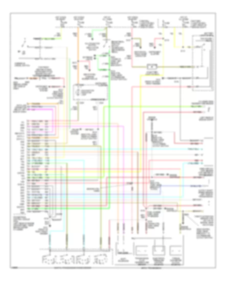
4.2L, A/T Wiring Diagram, 4R70W for Ford Econoline E250 2000


List of elements for 4.2L, A/T Wiring Diagram, 4R70W for Ford Econoline E250 2000:
- (eng control harn, near breakout to a/c pressure cutout switch)
- (engine ctrl harn)
- (fuel charge harn, near tp sensor)
- (in battery junction box)
- (left rear of engine compt)
- (top front center of eng) instrumentation engine coolant temperature sensor
- (trans ctrl harn, near breakout to dtr sensor)
- (trans ctrl harn, near trans)
- 4r70w transmission
- Abs system, warning buzzer module
- Battery junction box
- Battery junction box (left front of engine compt)
- Bpp
- Brake pedal position switch (on bracket, above brake pedal)
- C224
- C225
- C226
- Central junction box (behind left side of dash)
- Cht
- Cruise control system
- Cylinder head temperature sensor
- Data (+)
- Data (-)
- Data link connector (below left side of dash)
- Digital transmission range sensor
- Ect
- Electronic pressure control solenoid
- Eng compt)
- Engine controls
- Epc
- Exterior lights
- Fuse 10a
- Fuse 15a
- Fuse 30a
- Fuse 5a
- G101 (front of right front fender)
- G202 (behind upper left side of dash)
- Gen data
- Gnd
- Hot at all times
- Hot in run or start
- Ignition coil, radio noise capacitor
- Instrument cluster
- Instrument cluster system
- Kapwr
- Maf
- Malfunction indicator lamp
- Mass airflow (maf) sensor (top center of engine compt)
- Mil
- Multifunction switch, deavtiator switch
- Nca
- Od off
- Oss
- Output shaft speed sensor (left side of transmission)
- Overdrive cancel switch
- Pcm diode
- Pcm power relay
- Powertrain control module (pcm) (left rear of engine compartment, near brake master cylinder)
- Pwr in
- Red
- S100
- S102
- S103
- S110
- S127
- S133 (eng ctrl harn near a/c press cutout switch)
- S134 (eng ctrl harn, near a/c pressure cutout switch)
- S135 (eng ctrl harn, near a/c press cutout switch)
- S137 (eng ctrl harn, near breakout to pcm)
- S138
- S140
- S142
- S167
- S175
- S213
- S268
- Shift solenoids
- Sig rtn
- Speedometer
- Ssa
- Ssb
- Tcc
- Tcil
- Tcs
- Tft
- Throttle position sensor (tps) (on top of engine, near air intake)
- Torque converter clutch solenoid
- Tps
- Tr1
- Tr2
- Tr3
- Tr4
- Transmission fluid temperature sensor
- Vref
- Vss
4.6L
4.6L, A/T Wiring Diagram, 4R70W for Ford Econoline E250 2000
List of elements for 4.6L, A/T Wiring Diagram, 4R70W for Ford Econoline E250 2000:
- (eng control harn, near breakout to a/c pressure cutout switch)
- (engine ctrl harn)
- (fuel charge harn, near tp sensor)
- (in battery junction box)
- (left rear of engine compt)
- (top front center of eng) instrumentation engine coolant temperature sensor
- (trans ctrl harn, near trans)
- 4r70w transmission
- Abs system, warning buzzer module
- Battery junction box
- Battery junction box (left front of engine compt)
- Bpp
- Brake pedal position switch (on bracket, above brake pedal)
- C224
- C225
- C226
- Central junction box (behind left side of dash)
- Cht
- Cruise control system
- Cylinder head temperature sensor
- Data (+)
- Data (-)
- Data link connector (below left side of dash)
- Digital transmission range sensor
- Ect
- Electronic pressure control solenoid
- Eng compt)
- Engine controls
- Epc
- Exterior lights
- Fuse 10a
- Fuse 15a
- Fuse 30a
- Fuse 5a
- G101 (front of right front fender)
- G202 (behind upper left side of dash)
- Gen data
- Gnd
- Hot at all times
- Hot in run or start
- Ignition coil, radio noise capacitor
- Instrument cluster
- Instrument cluster system
- Kapwr
- Maf
- Malfunction indicator lamp
- Mass airflow (maf) sensor (top center of engine compt)
- Mil
- Multifunction switch, deavtiator switch
- Nca
- Od off
- Oss
- Output shaft speed sensor (left side of transmission)
- Overdrive cancel switch
- Pcm diode
- Pcm power relay
- Powertrain control module (pcm) (left rear of engine compartment, near brake master cylinder)
- Pwr in
- Red
- S102
- S103
- S110
- S127
- S133 (eng ctrl harn near a/c press cutout switch)
- S134 (eng ctrl harn, near a/c pressure cutout switch)
- S135 (eng ctrl harn, near a/c press cutout switch)
- S137 (eng ctrl harn, near breakout to pcm)
- S138
- S140
- S142
- S167
- S175
- S213
- S268
- Shift solenoids
- Sig rtn
- Speedometer
- Ssa
- Ssb
- Tcc
- Tcil
- Tcs
- Tft
- Throttle position sensor (tps) (on top of engine, near air intake)
- Torque converter clutch solenoid
- Tps
- Tr1
- Tr2
- Tr3
- Tr4
- Transmission fluid temperature sensor
- Vref
- Vss
5.4L
5.4L, A/T Wiring Diagram, 4R70W for Ford Econoline E250 2000
List of elements for 5.4L, A/T Wiring Diagram, 4R70W for Ford Econoline E250 2000:
- (eng control harn, near breakout to a/c pressure cutout switch)
- (engine ctrl harn)
- (fuel charge harn, near tp sensor)
- (in battery junction box)
- (left rear of engine compt)
- (top front center of eng) instrumentation engine coolant temperature sensor
- (trans ctrl harn, near trans)
- 4r70w transmission
- Abs system, warning buzzer module
- Battery junction box
- Battery junction box (left front of engine compt)
- Bpp
- Brake pedal position switch (on bracket, above brake pedal)
- C224
- C225
- C226
- Central junction box (behind left side of dash)
- Cht
- Cruise control system
- Cylinder head temperature sensor
- Data (+)
- Data (-)
- Data link connector (below left side of dash)
- Digital transmission range sensor
- Ect
- Electronic pressure control solenoid
- Eng compt)
- Engine controls
- Epc
- Exterior lights
- Fuse 10a
- Fuse 15a
- Fuse 30a
- Fuse 5a
- G101 (front of right front fender)
- G202 (behind upper left side of dash)
- Gen data
- Gnd
- Hot at all times
- Hot in run or start
- Ignition coil, radio noise capacitor
- Instrument cluster
- Instrument cluster system
- Kapwr
- Maf
- Malfunction indicator lamp
- Mass airflow (maf) sensor (top center of engine compt)
- Mil
- Multifunction switch, deavtiator switch
- Nca
- Od off
- Oss
- Output shaft speed sensor (left side of transmission)
- Overdrive cancel switch
- Pcm diode
- Pcm power relay
- Powertrain control module (pcm) (left rear of engine compartment, near brake master cylinder)
- Pwr in
- Red
- S102
- S103
- S110
- S127
- S133 (eng ctrl harn near a/c press cutout switch)
- S134 (eng ctrl harn, near a/c pressure cutout switch)
- S135 (eng ctrl harn, near a/c press cutout switch)
- S137 (eng ctrl harn, near breakout to pcm)
- S138
- S140
- S142
- S167
- S175
- S213
- S268
- Shift solenoids
- Sig rtn
- Speedometer
- Ssa
- Ssb
- Tcc
- Tcil
- Tcs
- Tft
- Throttle position sensor (tps) (on top of engine, near air intake)
- Torque converter clutch solenoid
- Tps
- Tr1
- Tr2
- Tr3
- Tr4
- Transmission fluid temperature sensor
- Vref
- Vss

 Čeština
 Dansk
Dansk Deutsch
 Ελληνικά
 English
 English
 Español
 Suomi
Suomi Français
 Français
 עברית
עברית Hrvatski
 Magyar
 Italiano
 한국어
한국어 Nederlands
 Polski
 Português
 Português
 Română
 Русский
 Slovenčina
 Slovenščina
 Svenska
 Türkçe
 中文 (中国)