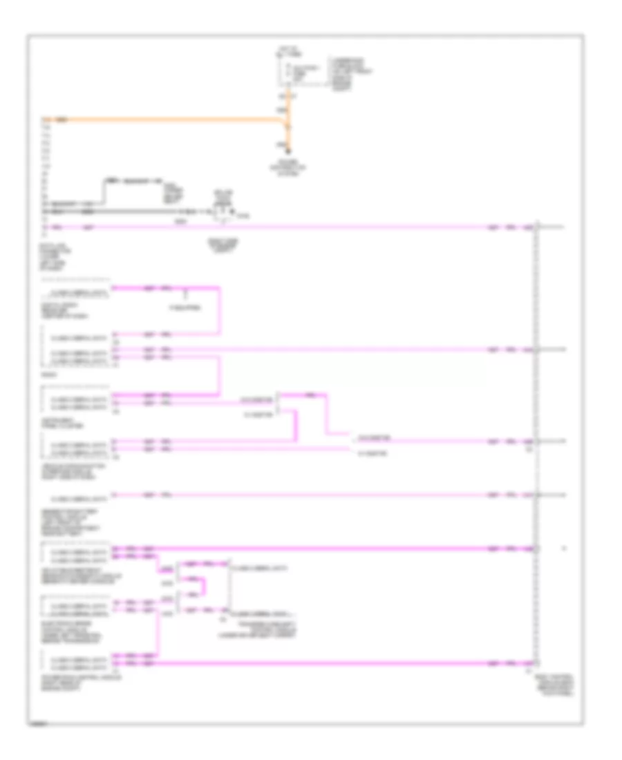
СИСТЕМА ПЕРЕДАЧИ ДАННЫХ
Электросхема линии передачи данных CAN для GMC Canyon 2007
 https://portal-diagnostov.com/license.html
Automotive Electricians Portal FZCO
Automotive Electricians Portal FZCO
https://portal-diagnostov.com/license.html
https://portal-diagnostov.com/license.html
Automotive Electricians Portal FZCO
Automotive Electricians Portal FZCO
Электросхема линии передачи данных CAN для GMC Canyon 2007 - Список элементов:
- (right side of engine compt)
- 2wd
- 4wd
- A38
- A39
- A41
- A42
- A44
- A47
- Aux pwr 1 fuse 20a
- Body control module (bcm) (behind right kick panel)
- Class 2 serial data
- Data link connector (lower left side of dash)
- Digital radio receiver (center of dash)
- Electronic brake control module (inner left frame rail, beside transmission)
- G106
- G300 (under driver seat)
- Generator battery control module (left front of engine compartment, near battery)
- Hot at all times
- If equipped
- Inflatable restraint sensing & diagnostic module (beneath center console)
- Instrument panel cluster
- Power distribution system
- Powertrain control module (right rear of engine compt)
- Radio
- S200
- S201
- Splice pack sp106
- Transfer case shift control module (under driver seat carpet)
- Underhood fuse block (on left front side of engine compt)
- Vehicle communication interface module (right side of dash)
- W/ onstar
- W/o onstar
 Čeština
 Dansk
Dansk Deutsch
 Ελληνικά
 English
 English
 Español
 Suomi
Suomi Français
 Français
 עברית
עברית Hrvatski
 Magyar
 Italiano
 한국어
한국어 Nederlands
 Polski
 Português
 Português
 Română
 Русский
 Slovenčina
 Slovenščina
 Svenska
 Türkçe
 中文 (中国)
 日本語
日本語
