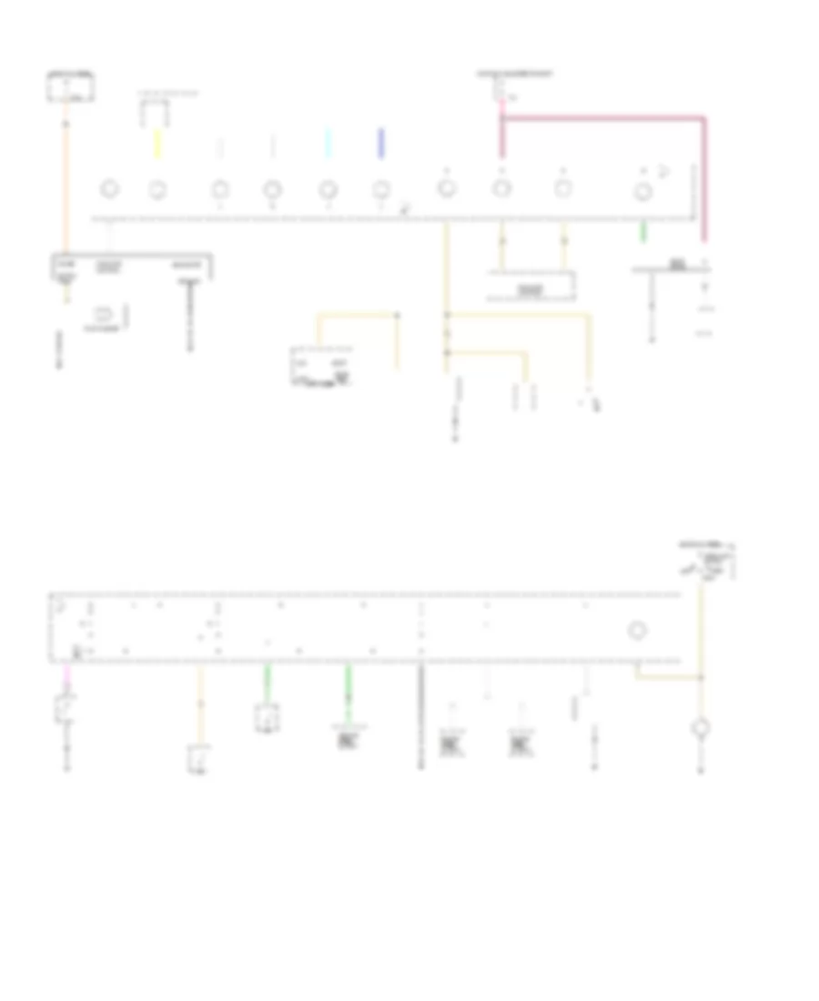
INSTRUMENT CLUSTER
Instrument Cluster Wiring Diagram, Base for Pontiac Sunbird LE 1994
 https://portal-diagnostov.com/license.html
Automotive Electricians Portal FZCO
Automotive Electricians Portal FZCO
https://portal-diagnostov.com/license.html
https://portal-diagnostov.com/license.html
Automotive Electricians Portal FZCO
Automotive Electricians Portal FZCO
List of elements for Instrument Cluster Wiring Diagram, Base for Pontiac Sunbird LE 1994:
-
-
- fuse block
- r
- (center of i/p)
- (vin h)
- (vin t)
- (w/ drl) (w/o drl)
- Abs lamp module (behind i/p, right of steering column)
- Acc
- Antilock brake indicator
- Brake fluid level switch (left rear of engine compt) (closed w/ low brake fluid level)
- Brake indicator
- Brake tell- tale
- Bulb test
- Check oil indicator
- Convenience center (behind i/p)
- Ctsy fuse 20a
- Daytime running lamps module (behind left side of i/p)
- Daytime running lamps on indicator
- Electronic brake control module (left rear of engine compt)
- Engine coolant temperature gauge
- Engine coolant temperature sender (left side of engine compt)
- Exterior lights system
- Fasten belts indicator
- Float magnet
- Fuel gauge
- Fuel gauge sender (top center of fuel tank) (full-90 ) (empty-0 )
- Fuel pump/ oil pressure switch (right front of engine compt) (open above 14kpa,2psi)
- Fuse block
- G104 (left rear of engine compt) g100 (left front of engine compt)
- G205 (behind i/p, right of steering column)
- G206
- G300 (below left front seat)
- Gages fuse 10a
- Generator (right front of engine compt)
- Ground
- Head
- Headlamp switch
- Headlamp switch assembly
- Headlights system
- Hi beam indicator
- Hot at all times
- Hot in run, bulb test or start
- Ignition switch
- Illum- ination (4 bulbs)
- Indicator control
- Instrument cluster
- Interior lights system
- Left turn indicator
- Lock
- Low oil warning module (behind left side of i/p)
- Malfunction indicator
- Multi- function alarm module
- Nca
- Odometer
- Off
- Off
- Oil level switch (on oil pan) (opens with low oil level)
- Oil pressure indicator
- Park
- Park brake input
- Park brake switch (open with park brake released)
- Power
- Powertrain control module (behind right of i/p)
- Powertrain control module (behind right side of i/p)
- Right turn indicator
- Run
- Shift indicator (m/t only)
- Solid state
- Speedometer
- Start
- Switch input
- T tan
- Tail lamps
- Tan
- Vehicle speed output
- Volts indicator
- W/ drl only
- With drl only
Instrument Cluster Wiring Diagram, Gauges for Pontiac Sunbird LE 1994
 https://portal-diagnostov.com/license.html
Automotive Electricians Portal FZCO
Automotive Electricians Portal FZCO
https://portal-diagnostov.com/license.html
https://portal-diagnostov.com/license.html
Automotive Electricians Portal FZCO
Automotive Electricians Portal FZCOList of elements for Instrument Cluster Wiring Diagram, Gauges for Pontiac Sunbird LE 1994:
-
- (vin h)
- (vin t)
- (vin t) (vin h)
- (w/o drl)
- 90 ) 35 )
- Abs lamp module (behind i/p, right of steering column)
- Acc
- Antilock brake indicator
- B11 c4
- Brake fluid level switch (left rear of engine compt) (close w/ low brake fluid level)
- Brake indicator
- Bulb test
- C2 c1
- C2 electronic brake control module (left rear of engine compt)
- C3 (vin t) (vin h)
- C3 (vin t) (vin h) powertrain control module (behind right side of i/p)
- Check gauges buffer
- Check gauges indicator
- Check oil indicator
- Convenience center (behind i/p)
- Ctsy fuse 20a
- Daytime running lamps module (behind left side of i/p)
- Daytime running lamps on indicator
- E7 a5
- Electronic brake control module (left rear of engine compt)
- Electronic ignition system (right front of engine)
- Engine coolant temperature gauge
- Engine coolant temperature sender (left side of engine)
- Engine speed output
- Exterior lights system
- F6 a4
- Fasten belts indicator
- Float magnet
- Fuel gauge
- Fuel gauge sender (top center of fuel tank) (full-90 ) (empty-0 )
- Fuel pump/ oil pressure sender/switch (right front of engine compt) (high- (low-
- Fuse block
- G100 (left front of engine compt)
- G104 (left rear of engine compt) g100 (left front of engine compt)
- G206 (behind center of i/p)
- G206 (center of i/p)
- G300 (below left front seat)
- Gages fuse 10a
- Ground
- Head
- Headlamp switch
- Headlamp switch assembly
- Headlights system
- Hi beam indicator
- Hot at all times
- Hot in run, bulb test or start
- Ignition switch
- Illum- ination (6 bulbs)
- Indicator control
- Instrument cluster
- Interior lights system
- Left turn indicator
- Lock
- Low coolant indicator
- Low oil warning module (behind left side of i/p)
- Malfunction indicator
- Multi- function alarm module
- Nca
- Off
- Oil level switch (upper right rear of engine) (opens w/ low oil level)
- Oil pressure gauge
- Park
- Park brake switch (open w/ park brake released)
- Power
- Powertrain control module (behind right side of i/p)
- Right turn indicator
- Run
- Shift indicator (m/t only)
- Solid state
- Speedometer
- Start
- Surge tank low coolant switch (right side of engine)
- Switch input
- Tachometer
- Tail lamps
- Tan
- Vehicle speed output
- Vin h
- Vin t
- Vin t only
- Voltmeter
- W/ drl only
- With drl only

 Čeština
 Dansk
Dansk Deutsch
 Ελληνικά
 English
 English
 Español
 Suomi
Suomi Français
 Français
 עברית
עברית Hrvatski
 Magyar
 Italiano
 한국어
한국어 Nederlands
 Polski
 Português
 Português
 Română
 Русский
 Slovenčina
 Slovenščina
 Svenska
 Türkçe
 中文 (中国)
