SUPPLEMENTAL RESTRAINTS
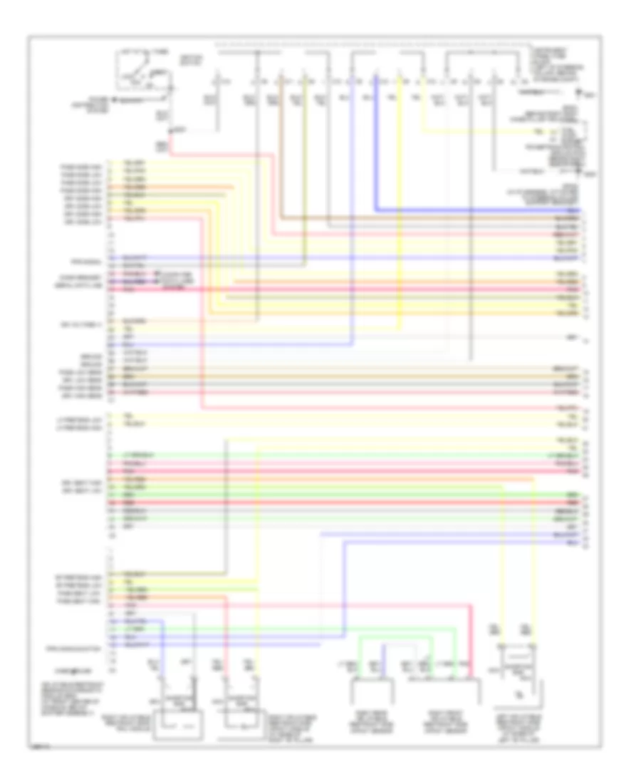
Supplemental Restraints Wiring Diagram (1 of 4) for Pontiac Vibe 2007
 https://portal-diagnostov.com/license.html
Automotive Electricians Portal FZCO
Automotive Electricians Portal FZCO
https://portal-diagnostov.com/license.html
https://portal-diagnostov.com/license.html
Automotive Electricians Portal FZCO
Automotive Electricians Portal FZCO
List of elements for Supplemental Restraints Wiring Diagram (1 of 4) for Pontiac Vibe 2007:
- Acc
- C10
- C11
- C12
- Case ground
- Computer data lines system
- Diagn request
- Drv high sens
- Drv low sens
- Drv seat high
- Drv seat low
- Drv side high
- Drv side low
- Fuel pump cutoff
- G200
- G201
- Ground
- Hot at all times
- Ign voltage (+)
- Ignition switch
- Inflatable restraint sensing & diagnostic module (sdm) (at front center of console, below shifter assembly)
- Instrument panel fuse block (left of steering column, behind storage compt)
- Left inflatable restraint side impact module (at base of left "b" pillar)
- Lf pretens high
- Lf pretens low
- Lock
- Nca
- Pass high sens
- Pass low sens
- Pass seat high
- Pass seat low
- Pass side high
- Pass side low
- Pnk
- Power distribution system
- Powertrain control module (pcm) (behind right side of dash)
- Pps communication
- Pps signal
- Red
- Rf pretens high
- Rf pretens low
- Right front inflatable restraint side impact sensor
- Right inflatable restraint roof rail module
- Right inflatable restraint side impact module (at base of right "b" pillar)
- Right rear inflatable restraint side impact sensor
- S237
- Serial data line
- Shorting bar
- Sp200 (in i/p harness, attached to steering column support bracket)
- Sp201 (behind right body hinge pillar trim panel)
- Start
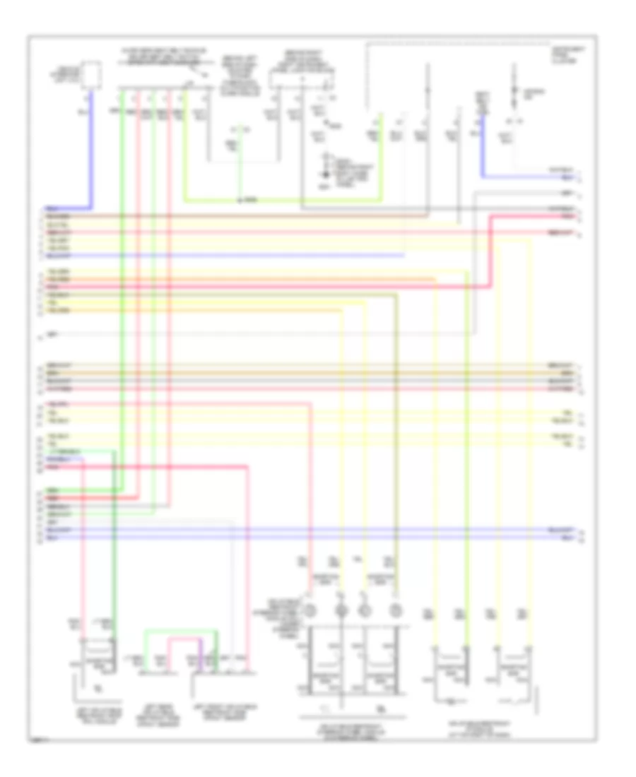
Supplemental Restraints Wiring Diagram (2 of 4) for Pontiac Vibe 2007
 https://portal-diagnostov.com/license.html
Automotive Electricians Portal FZCO
Automotive Electricians Portal FZCO
https://portal-diagnostov.com/license.html
https://portal-diagnostov.com/license.html
Automotive Electricians Portal FZCO
Automotive Electricians Portal FZCOList of elements for Supplemental Restraints Wiring Diagram (2 of 4) for Pontiac Vibe 2007:
- (behind left side of dash, mounted to dash fuse block) multifunction alarm module
- (behind right side of dash) right instrument panel junction block
- (in driver's seat belt buckle) driver seat belt switch (open with belt buckled)
- Air bag ind
- G201
- Inflatable restraint ip module (at top right of dash)
- Inflatable restraint steering wheel module (in steering wheel)
- Inflatable restraint steering wheel module coil (under steering wheel)
- Instrument panel cluster
- Left front inflatable restraint side impact sensor
- Left inflatable restraint roof rail module
- Left rear inflatable restraint side impact sensor
- Nca
- Pnk
- Red
- S222
- S226
- Seat belt ind ctrl
- Shorting bar
- Sp201 (behind right body hinge pillar trim panel)
- Vehicle interface unit (viu)
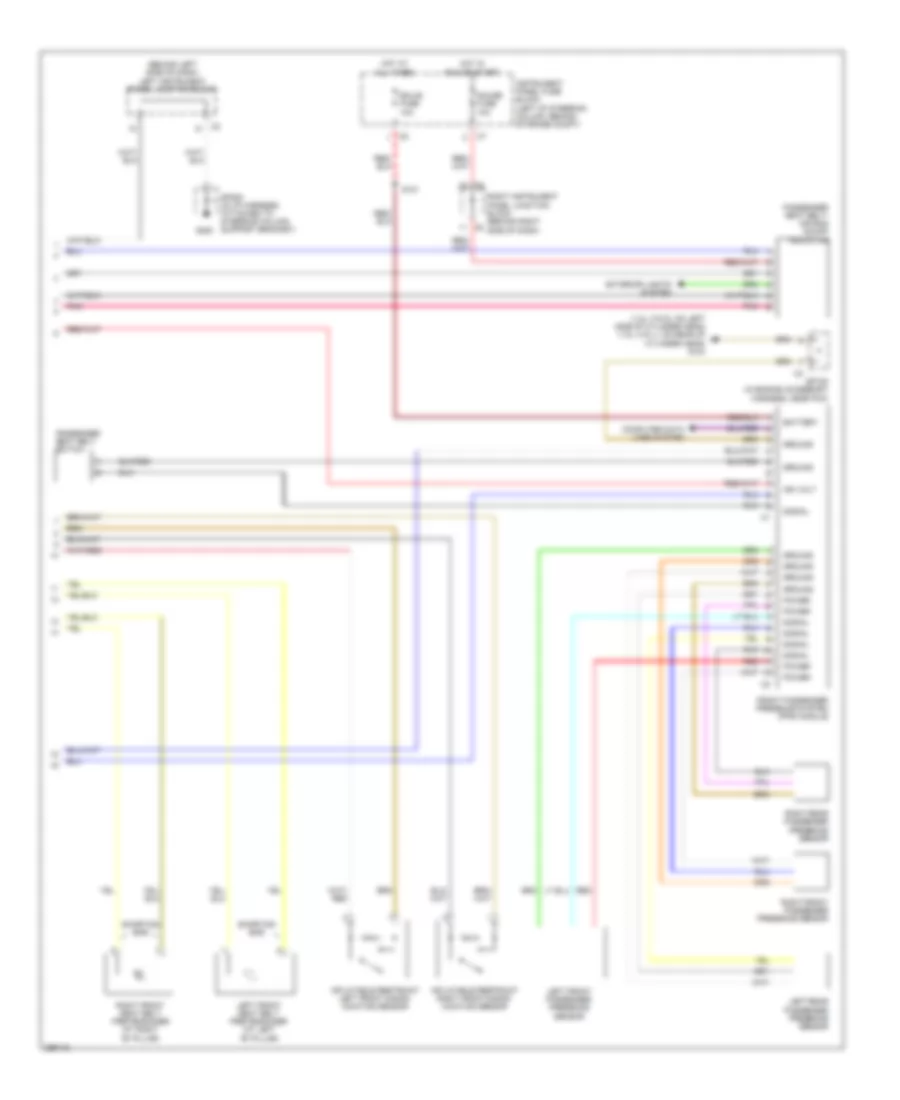
Supplemental Restraints Wiring Diagram (3 of 4) for Pontiac Vibe 2007
 https://portal-diagnostov.com/license.html
Automotive Electricians Portal FZCO
Automotive Electricians Portal FZCO
https://portal-diagnostov.com/license.html
https://portal-diagnostov.com/license.html
Automotive Electricians Portal FZCO
Automotive Electricians Portal FZCOList of elements for Supplemental Restraints Wiring Diagram (3 of 4) for Pontiac Vibe 2007:
- (1.8l (vin 8): on left side of cylinder head) (1.8l (vin l): on rear of cylinder head) g104
- (behind left side of dash) left instrument panel junction block
- Battery
- Computer data lines system
- Ecu-b fuse 10a
- Exterior lights system
- Front passenger presence system (pps) module
- G200
- Gauge fuse 10a
- Ground
- Hot at all times
- Hot in run or start
- Ign volt
- Inflatable restraint left front discri- minating sensor
- Inflatable restraint right front discri- minating sensor
- Instrument panel fuse block (left of steering column, behind storage compt)
- Left front passenger presence sensor
- Left front seat belt pretensioner (at left "b" pillar)
- Left rear passenger presence sensor
- Passenger seat belt switch
- Passenger seat belt/ air bag on/off indicator
- Pnk
- Power
- Red
- Right front passenger presence sensor
- Right front seat belt pretensioner (at right "b" pillar)
- Right instrument panel junction block (behind right side of dash)
- Right rear passenger presence sensor
- S121
- Shorting bar
- Signal
- Sp108 (in engine accessory harness, near pcm)
- Sp200 (in i/p harness, attached to steering column support bracket)
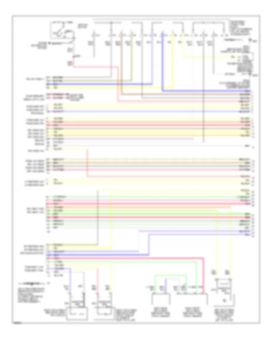
Supplemental Restraints Wiring Diagram (4 of 4) for Pontiac Vibe 2007
 https://portal-diagnostov.com/license.html
Automotive Electricians Portal FZCO
Automotive Electricians Portal FZCO
https://portal-diagnostov.com/license.html
https://portal-diagnostov.com/license.html
Automotive Electricians Portal FZCO
Automotive Electricians Portal FZCOList of elements for Supplemental Restraints Wiring Diagram (4 of 4) for Pontiac Vibe 2007:
- Acc
- C10
- C11
- C12
- Case ground
- Computer data lines system
- Diagn request
- Drv high sens
- Drv low sens
- Drv seat high
- Drv seat low
- Drv side high
- Drv side low
- Fuel pump cutoff
- G200
- G201
- Ground
- Hot at all times
- Ign voltage (+)
- Ignition switch
- Inflatable restraint sensing & diagnostic module (sdm) (at front center of console, below shifter assembly)
- Instrument panel fuse block (left of steering column, behind storage compt)
- Left inflatable restraint side impact module (at base of left "b" pillar)
- Lf pretens high
- Lf pretens low
- Lock
- Nca
- Pass high sens
- Pass low sens
- Pass seat high
- Pass seat low
- Pass side high
- Pass side low
- Pnk
- Power distribution system
- Powertrain control module (pcm) (behind right side of dash)
- Pps communication
- Pps signal
- Red
- Rf pretens high
- Rf pretens low
- Right front inflatable restraint side impact sensor
- Right inflatable restraint roof rail module
- Right inflatable restraint side impact module (at base of right "b" pillar)
- Right rear inflatable restraint side impact sensor
- S237
- Serial data line
- Shorting bar
- Sp200 (in i/p harness, attached to steering column support bracket)
- Sp201 (behind right body hinge pillar trim panel)
- Start

 Čeština
 Dansk
Dansk Deutsch
 Ελληνικά
 English
 English
 Español
 Suomi
Suomi Français
 Français
 עברית
עברית Hrvatski
 Magyar
 Italiano
 한국어
한국어 Nederlands
 Polski
 Português
 Português
 Română
 Русский
 Slovenčina
 Slovenščina
 Svenska
 Türkçe
 中文 (中国)
