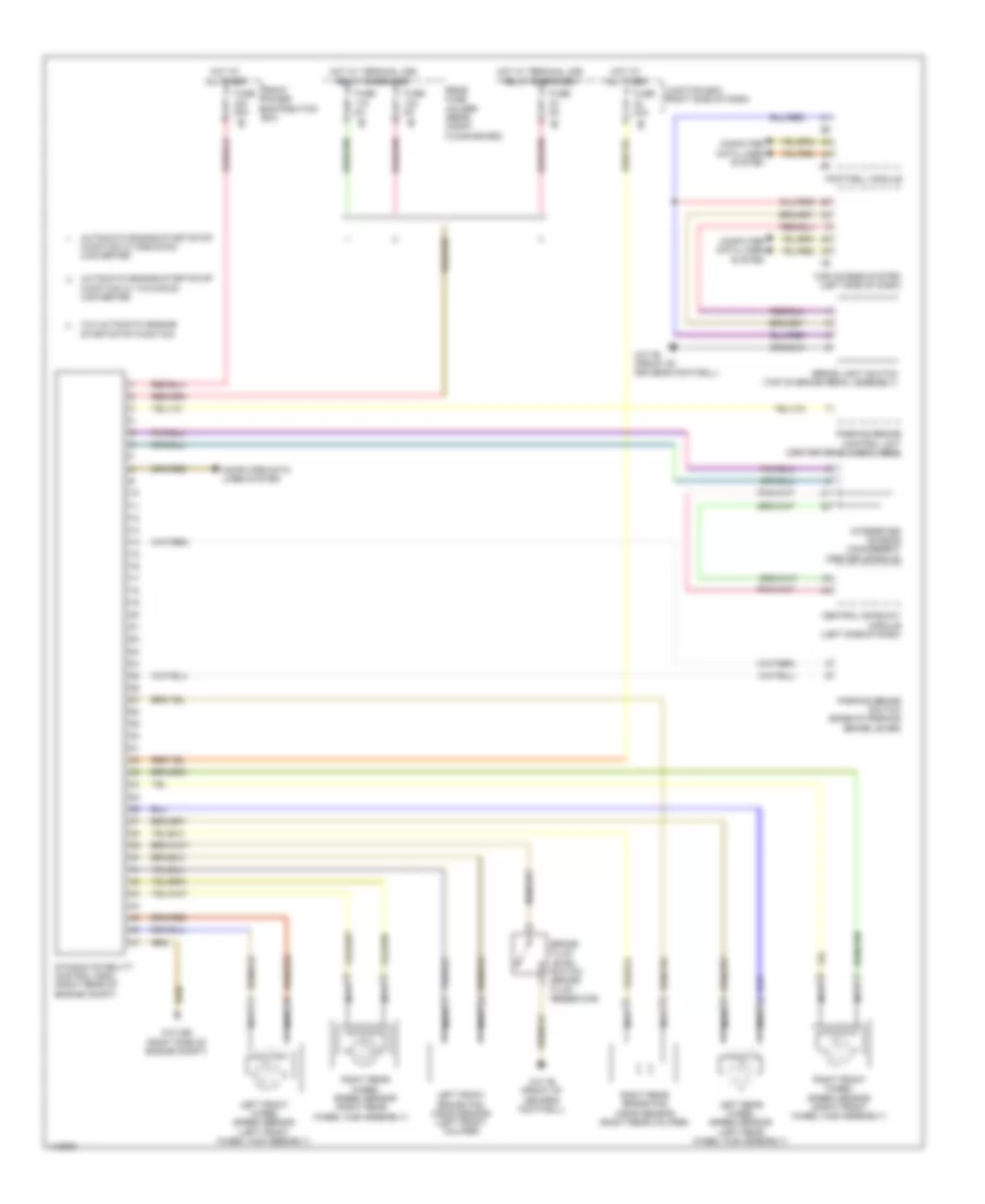
ANTI-LOCK BRAKES
Anti-lock Brakes Wiring Diagram for BMW X3 28i 2013
 https://portal-diagnostov.com/license.html
Automotive Electricians Portal FZCO
Automotive Electricians Portal FZCO
https://portal-diagnostov.com/license.html
https://portal-diagnostov.com/license.html
Automotive Electricians Portal FZCO
Automotive Electricians Portal FZCO
List of elements for Anti-lock Brakes Wiring Diagram for BMW X3 28i 2013:
- (right rear wheel hub assembly)
- Automatic engine start/stop function w/ one dc/dc converter
- Automatic engine start/stop function w/ two dc/dc converter
- Brake fluid level switch (brake fluid reservoir)
- Brake light switch (top of brake pedal assembly)
- Car access system (left side of dash)
- Central gateway module (left side of dash)
- Computer data lines system
- Dynamic stability control (dsc) (right rear of engine compt)
- Footwell module
- Front power distribution box
- Fuse 30a
- Fuse 50a
- Fuse 5a
- Hot at all times
- Hot w/ terminal 30b relay energized
- Integrated chassis management (center console)
- Junction box (right side of dash)
- Left front brake pad wear sensor (left front caliper)
- Left front wheel speed sensor (left front wheel hub assembly)
- Left rear wheel speed sensor (left rear wheel hub assembly)
- Nca
- Parking brake control unit (center rear cargo area)
- Parking brake switch (base of parking brake lever)
- Rear fuse holder (rear compt floor board)
- Right front wheel speed sensor (right front wheel hub assembly)
- Right rear brake pad wear sensor (right rear caliper)
- Right rear wheel speed sensor
- W/o automatic engine start/stop function
- Z10 24b (right side of engine compt)
- Z10 7b (front of driver's footwell)
 Čeština
 Dansk
Dansk Deutsch
 Ελληνικά
 English
 English
 Español
 Suomi
Suomi Français
 Français
 עברית
עברית Hrvatski
 Magyar
 Italiano
 한국어
한국어 Nederlands
 Polski
 Português
 Português
 Română
 Русский
 Slovenčina
 Slovenščina
 Svenska
 Türkçe
 中文 (中国)
 日本語
日本語
