ENGINE PERFORMANCE
5.4L
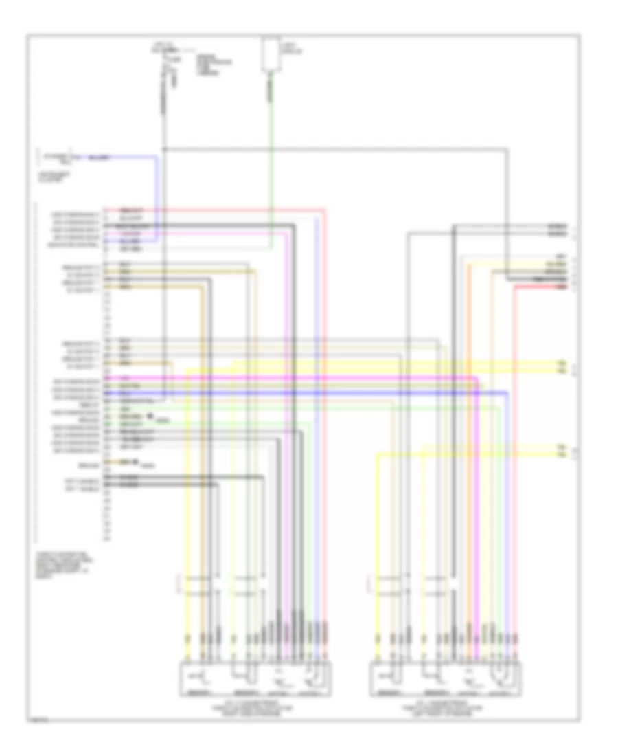
5.4L, Electronic Throttle Control Wiring Diagram (1 of 2) for BMW 750iL 1996
 https://portal-diagnostov.com/license.html
Automotive Electricians Portal FZCO
Automotive Electricians Portal FZCO
https://portal-diagnostov.com/license.html
https://portal-diagnostov.com/license.html
Automotive Electricians Portal FZCO
Automotive Electricians Portal FZCO
List of elements for 5.4L, Electronic Throttle Control Wiring Diagram (1 of 2) for BMW 750iL 1996:
- 5v sig pot 1
- 5v sig pot 2
- Cos winding sig a
- Cos winding sig b
- Cyl 1-6 electronic throttle position actuator (left front of engine)
- Cyl 7-12 electronic throttle position actuator (right side of engine)
- Engine electronics fuse carrier
- Fuse 30a
- Ground
- Ground pot 1
- Ground pot 2
- Hot at all times
- Indicator control
- Instrument cluster
- Light module
- Motor 1
- Motor 2
- Pot 1 shield
- Pot 2 shield
- Red
- Sensor 1
- Sensor 2
- Shield
- Sin winding sig a
- Sin winding sig b
- Standby ind
- Term 87
- Throttle position control module (eml) (right rear side of engine compt, in e-box)
- X6452
- X6454
- X8680
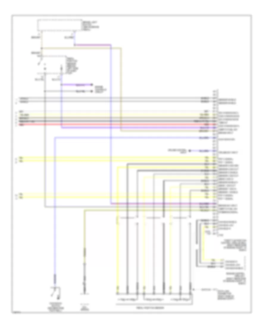
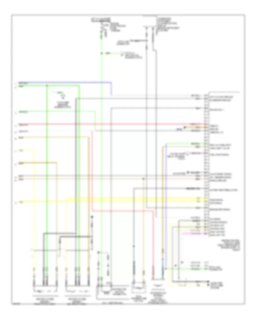
5.4L, Electronic Throttle Control Wiring Diagram (2 of 2) for BMW 750iL 1996
 https://portal-diagnostov.com/license.html
Automotive Electricians Portal FZCO
Automotive Electricians Portal FZCO
https://portal-diagnostov.com/license.html
https://portal-diagnostov.com/license.html
Automotive Electricians Portal FZCO
Automotive Electricians Portal FZCOList of elements for 5.4L, Electronic Throttle Control Wiring Diagram (2 of 2) for BMW 750iL 1996:
- (right rear side of engine compt, in e-box)
- Brake input
- Brake light switch (above brake pedal)
- Brake sw input
- Can bus hi
- Can bus low
- Can bus shield
- Coil spring
- Cos winding sig a
- Cos winding sig b
- Cruise control input
- Cruise sw input
- Data link connector (right side of engine compt)
- Engine control module ii
- Engine controls circuit
- Inertia fuel sw
- Kick down sw
- Kick-down switch (driver's side footwell)
- Nca
- Pedal position sensor
- Pedal position sensor (behind left side of dash top)
- Pot 1 signal
- Pot 2 signal
- Red
- Sens 1 sig out
- Sens 3 sig in
- Sensor 1 shield
- Sensor 1 sig in
- Sensor 2 shield
- Sensor 2 sig osc
- Sensor 2 sig out
- Sensor 3 sig out
- Sensor shield
- Sensor shield 3
- Shield
- Sin winding sig a
- Sin winding sig b
- Steering signal
- Term 87
- Throttle position control module (eml) (right rear side of engine compt, in e-box)
- Txd
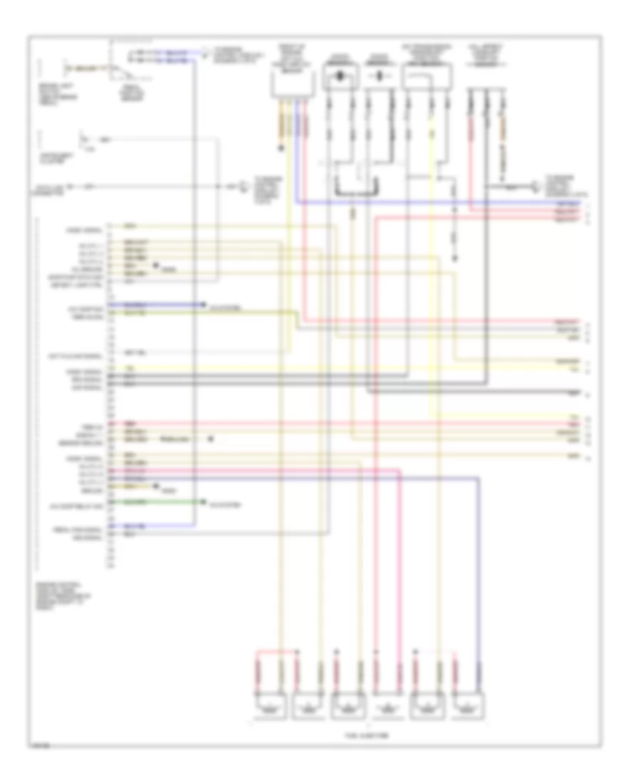
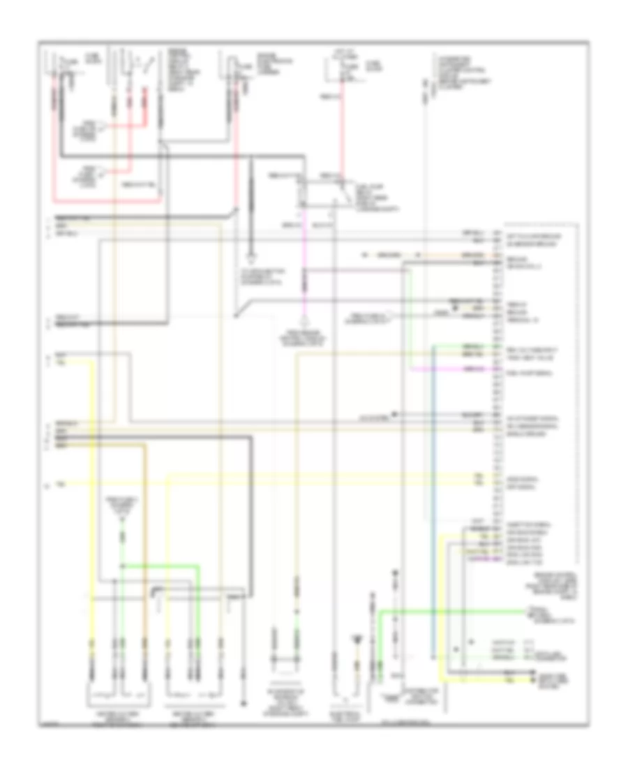
5.4L, Engine Controls Wiring Diagram (1 of 5) for BMW 750iL 1996
 https://portal-diagnostov.com/license.html
Automotive Electricians Portal FZCO
Automotive Electricians Portal FZCO
https://portal-diagnostov.com/license.html
https://portal-diagnostov.com/license.html
Automotive Electricians Portal FZCO
Automotive Electricians Portal FZCOList of elements for 5.4L, Engine Controls Wiring Diagram (1 of 5) for BMW 750iL 1996:
- (front of engine)
- (on transmission) crankshaft position/ rpm sensor 1
- A/c comp relay sig
- A/c comp sig
- A/c system
- Brake light switch (above brake pedal)
- Cmp signal
- Data link connector
- Detect lamp ctrl
- Dme rly 1
- Engine control module i (dme) (right rear side of engine compt, in e-box)
- Fuel injectors
- Ground
- Hall effect camshaft position sensor
- Ho2s1 signal
- Hot film maf signal
- Hot film mass airflow sensor
- Inj cyl 1
- Inj cyl 2
- Inj cyl 3
- Inj cyl 4
- Inj cyl 5
- Inj cyl 6
- Inj ground
- Instrument cluster
- Knock sensor 1
- Knock sensor 2
- Ks2 signal
- Nca
- Pedal pos signal
- Pedal position sensor
- Red
- Rpm signal
- Sair pump stg 2 sig
- Sensor ground
- Term 30
- Term 50 sig
- To engine control module ii (diagram 4 of 5)
- X16
- X6452
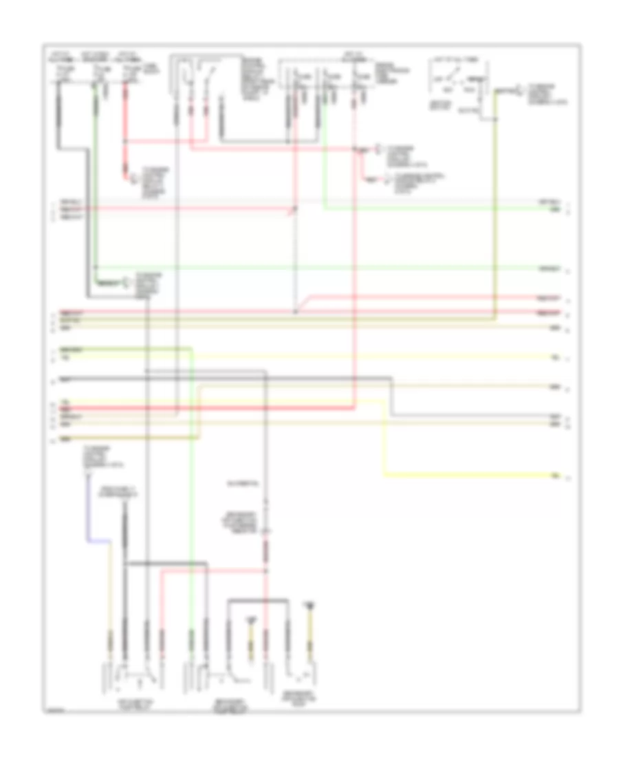
5.4L, Engine Controls Wiring Diagram (2 of 5) for BMW 750iL 1996
 https://portal-diagnostov.com/license.html
Automotive Electricians Portal FZCO
Automotive Electricians Portal FZCO
https://portal-diagnostov.com/license.html
https://portal-diagnostov.com/license.html
Automotive Electricians Portal FZCO
Automotive Electricians Portal FZCOList of elements for 5.4L, Engine Controls Wiring Diagram (2 of 5) for BMW 750iL 1996:
- Acc
- Air injection pump relay
- Engine control module relay 1 (right rear of engine compt, in e-box)
- Engine electronics fuse carrier
- From fuse 17 (diagram 5 of 5)
- Fuse 20a
- Fuse 30a
- Fuse 50a
- Fuse 5a
- Fuse 80a
- Fuse block
- Hot at all times
- Hot in run or start
- Ignition switch
- Off
- Red
- Run
- Secondary air injection pump
- Secondary air injection pump relay
- Secondary air injection pump series resistor
- Start
- To engine control module ii (diagram 4 of 5)
- To engine control module ii (diagram 5 of 5)
- To engine control module relay 2 (diagram 5 of 5)
- X10016
- X490
- X493
- X8680
5.4L, Engine Controls Wiring Diagram (3 of 5) for BMW 750iL 1996
 https://portal-diagnostov.com/license.html
Automotive Electricians Portal FZCO
Automotive Electricians Portal FZCO
https://portal-diagnostov.com/license.html
https://portal-diagnostov.com/license.html
Automotive Electricians Portal FZCO
Automotive Electricians Portal FZCOList of elements for 5.4L, Engine Controls Wiring Diagram (3 of 5) for BMW 750iL 1996:
- A/c standby signal
- A/c system
- Can bus high
- Can bus low
- Can bus shield
- Ckp signal
- Computer data lines system
- Cyl 1 ignition coil
- Data link connector
- Diag link rxd
- Diag link txd
- Distributor ignition connection
- Dual temperature switch
- Engine control module i (dme) (right rear side of engine compt, in e-box)
- Engine electronics fuse carrier
- Engine spd signal
- Evaporative emission valve 1 (right front of engine compt)
- Fuel pump signal
- Fuse 30a
- Ground
- Heated oxygen sensor 1 behind cat conv
- Heated oxygen sensor 1 front of cat conv
- Ho2s signal
- Hot film maf ground
- Hot w/ unloader relay energized
- Ign sig coil 1
- Inj signal
- Integrated instrument cluster control module (behind instrument x10114 cluster)
- Ks 1 sensor signal
- Nca
- O2 sensor ground
- Pgm voltage input
- Shield
- Shield ground
- Tank vent valve
- Term 87
- Terminal 15
- To cyl 2 ignition coil (diagram 5 of 5)
- To fuel pump c relay (diagram 5 of 5)
- To oxygen sensors (diagram 5 of 5)
- Water temp regulator
- X6452
- X8680
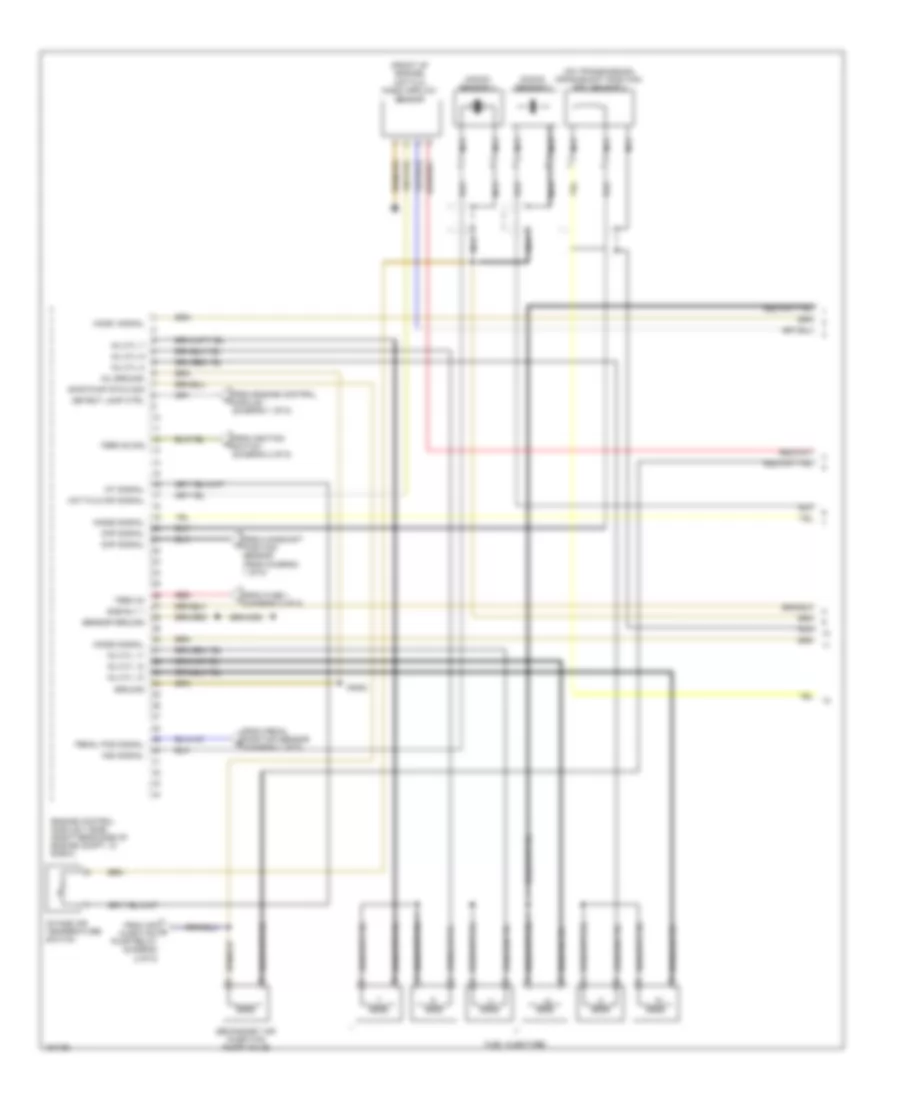
5.4L, Engine Controls Wiring Diagram (4 of 5) for BMW 750iL 1996
 https://portal-diagnostov.com/license.html
Automotive Electricians Portal FZCO
Automotive Electricians Portal FZCO
https://portal-diagnostov.com/license.html
https://portal-diagnostov.com/license.html
Automotive Electricians Portal FZCO
Automotive Electricians Portal FZCOList of elements for 5.4L, Engine Controls Wiring Diagram (4 of 5) for BMW 750iL 1996:
- (front of engine)
- (on transmission) crankshaft position/ rpm sensor 2
- Ckp signal
- Cmp signal
- Detect lamp ctrl
- Dme rly 1
- Engine control module ii (dme) (right rear side of engine compt, in e-box)
- From air m injection pump relay (diagram 2 of 5)
- From camshaft position sensor (from diagram 1 of 5)
- From engine control module i (diagram 1 of 5)
- From fuse 1 i (diagram 2 of 5)
- From ignition switch (diagram 2 of 5)
- From pedal position sensor (diagram 1 of 5)
- Fuel injectors
- Ground
- Ho2s1 signal
- Ho2s2 signal
- Hot film maf signal
- Hot film mass airflow sensor
- Iat signal
- Inj cyl 10
- Inj cyl 11
- Inj cyl 12
- Inj cyl 7
- Inj cyl 8
- Inj cyl 9
- Inj ground
- Intake air temperature switch
- Knock sensor 3
- Knock sensor 4
- Ks4 signal
- Nca
- Pedal pos signal
- Red
- Sair pump stg 2 sig
- Secondary air injection pump valve
- Sensor ground
- Term 30
- Term 50 sig
- X6453
5.4L, Engine Controls Wiring Diagram (5 of 5) for BMW 750iL 1996
 https://portal-diagnostov.com/license.html
Automotive Electricians Portal FZCO
Automotive Electricians Portal FZCO
https://portal-diagnostov.com/license.html
https://portal-diagnostov.com/license.html
Automotive Electricians Portal FZCO
Automotive Electricians Portal FZCOList of elements for 5.4L, Engine Controls Wiring Diagram (5 of 5) for BMW 750iL 1996:
- A/c standby signal
- A/c system
- Can bus high
- Can bus low
- Can bus shield
- Ckp signal
- Computer data lines system
- Cyl 2 ignition coil
- Data link connector
- Diag link rxd
- Diag link txd
- Distributor ignition connection
- Electrical fuel pump
- Engine control module ii (dme) (right rear side of engine compt, in e-box)
- Engine control module relay 2 (right rear of engine compt, in e-box)
- Engine electronics fuse carrier
- Evaporative emission valve 2 (right front of engine compt)
- From engine control module i (diagram 3 of 5)
- From fuse 1 o (diagram 2 of 5)
- From fuse 109 h (diagram 2 of 5)
- From fuse 24 l (diagram 2 of 5)
- From fuse 3 (diagram 3 of 5)
- From fuse 5 (diagram 3 of 5)
- Fuel pump relay (right rear side of luggage compt)
- Fuel pump signal
- Fuse 15a
- Fuse 30a
- Fuse block
- Ground
- Heated oxygen sensor 2 behind cat conv
- Heated oxygen sensor 2 front of cat conv
- Ho2s signal
- Hot at all times
- Hot film maf ground
- Ign sig coil 2
- Injection signal
- Integrated instrument cluster control module (behind instrument cluster)
- Ks 3 sensor signal
- Nca
- O2 sensor ground
- Pgm voltage input
- Red
- Shield
- Shield ground
- Tank vent valve
- Term 87
- Terminal 15
- To air injection pump relay (diagram 2 of 5)
- X10016
- X10114
- X494
- X6453
- X8680

 Čeština
 Dansk
Dansk Deutsch
 Ελληνικά
 English
 English
 Español
 Suomi
Suomi Français
 Français
 עברית
עברית Hrvatski
 Magyar
 Italiano
 한국어
한국어 Nederlands
 Polski
 Português
 Português
 Română
 Русский
 Slovenčina
 Slovenščina
 Svenska
 Türkçe
 中文 (中国)
