ENGINE PERFORMANCE
1.3L
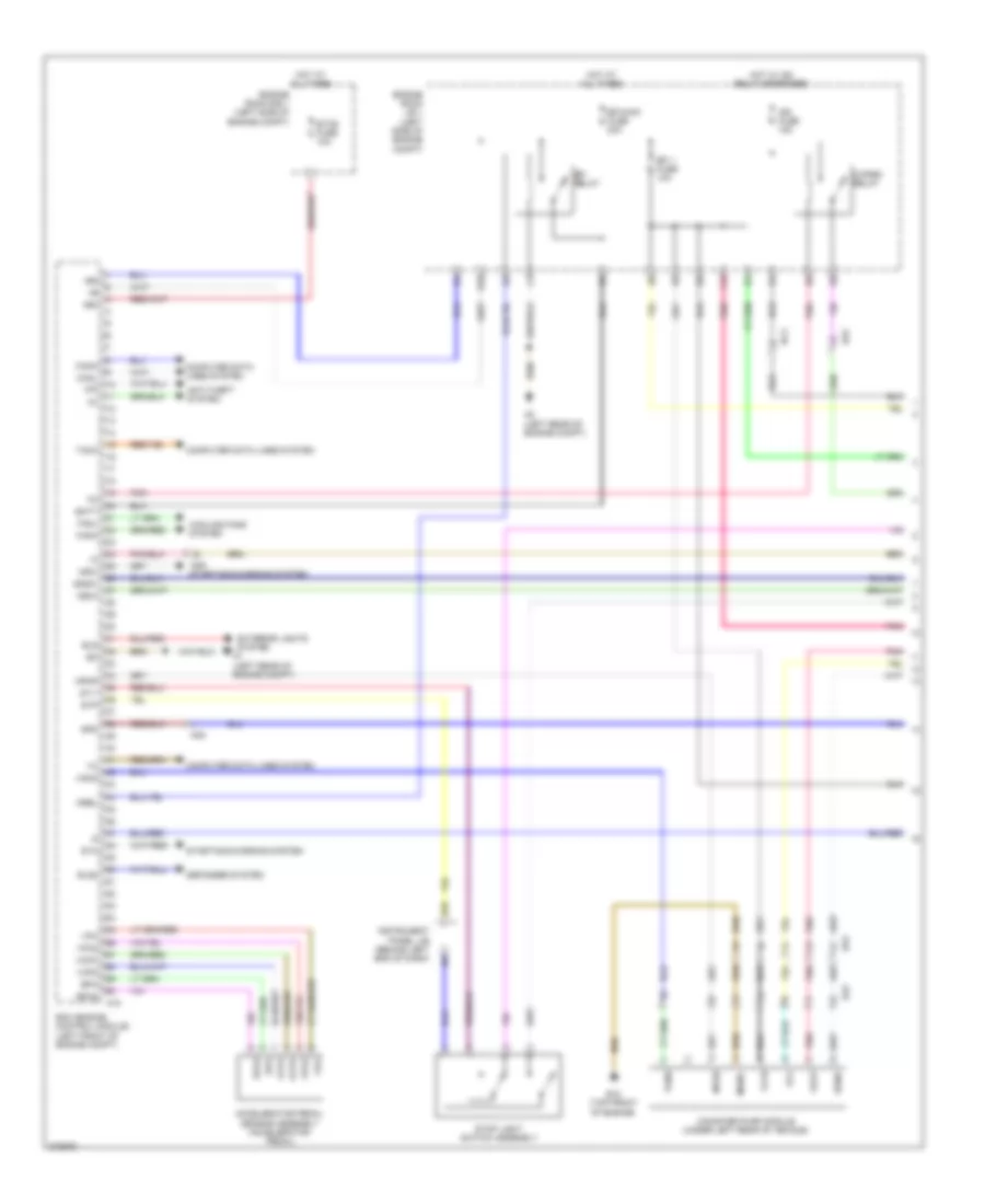
1.3L, Engine Performance Wiring Diagram (1 of 4) for Scion iQ 2014
 https://portal-diagnostov.com/license.html
Automotive Electricians Portal FZCO
Automotive Electricians Portal FZCO
https://portal-diagnostov.com/license.html
https://portal-diagnostov.com/license.html
Automotive Electricians Portal FZCO
Automotive Electricians Portal FZCO
List of elements for 1.3L, Engine Performance Wiring Diagram (1 of 4) for Scion iQ 2014:
- +b2
- +bm
- A18
- A2 (left rear of engine compt)
- Accelerator pedal sensor assembly (accelerator pedal)
- Ad4
- Ad5 starting/charging system
- Ag2
- Anti-theft system
- B10
- B12 (top front of engine)
- B35
- Ba2
- Batt
- Bc3
- C/open relay
- Canh
- Canister pump module (under left rear of vehicle)
- Canl
- Computer data lines system
- Cooling fans system
- Defogger system
- Ecm (engine control module) (left front of engine compt)
- Efi 1 fuse 10a
- Efi relay
- Efi-main fuse 20a
- Els
- Els2
- Engine room j/b 1 (left side of engine compt)
- Engine room r/b 1 (left side of engine compt)
- Epa
- Epa2
- Etcs fuse 10a
- Exterior lights system a1 (left rear of engine compt)
- F12
- Fanh
- Fanl
- Hot at all times
- Hot w/ ig2 relay energized
- Ign fuse 15a
- Igsw
- Imi
- Imo
- Instrument panel j/b (behind left end of dash)
- Mgnd
- Mpmp
- Mrel
- Mtrb
- Nsw
- Pnk
- Sdsw
- Sgnd
- Spd
- St1-
- Sta
- Starting/charging system
- Stop light switch assembly
- Stp
- Tach
- Vcc
- Vcp2
- Vcpa
- Vgnd
- Vlvb
- Vout
- Vpa
- Vpa2
- Vpmp
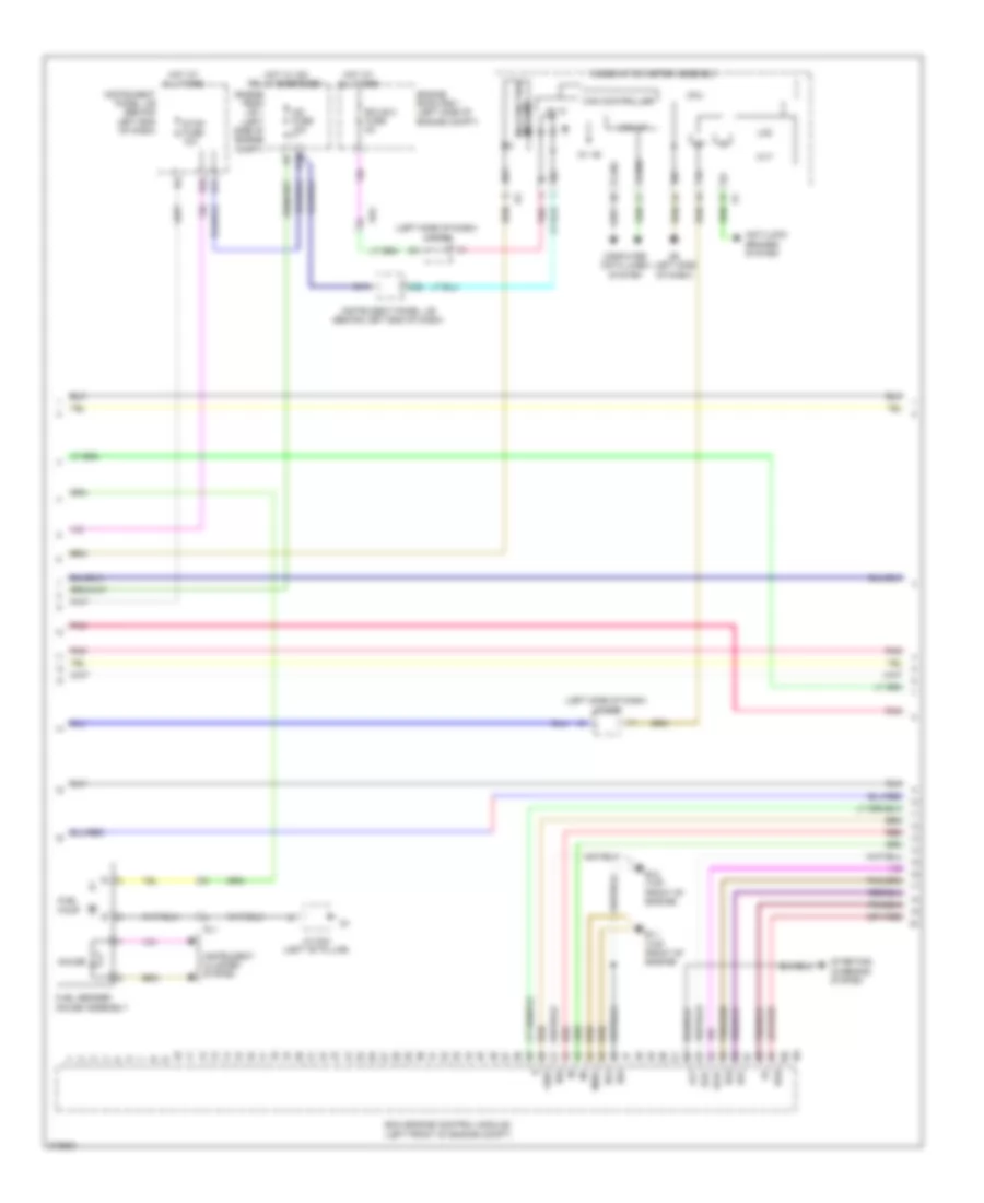
1.3L, Engine Performance Wiring Diagram (2 of 4) for Scion iQ 2014
 https://portal-diagnostov.com/license.html
Automotive Electricians Portal FZCO
Automotive Electricians Portal FZCO
https://portal-diagnostov.com/license.html
https://portal-diagnostov.com/license.html
Automotive Electricians Portal FZCO
Automotive Electricians Portal FZCOList of elements for 1.3L, Engine Performance Wiring Diagram (2 of 4) for Scion iQ 2014:
- (left side of dash)
- 5v +b
- 5v ic
- Ad2
- Alt
- Anti-lock brakes system
- B11 (top front of engine)
- B12 (top front of engine)
- B17
- B32
- C25
- Can controller
- Can i/f
- Canh
- Canl
- Combination meter assembly
- Computer data lines system
- Cpu
- Cvt
- D10
- D6 (left side of dash)
- Ds1
- Ds2
- Dsu
- E01
- E04
- Ecm (engine control module) (left front of engine compt)
- Ecu-b 2 fuse 5a
- Efi
- Engine room j/b 1 (left side of engine compt)
- Engine room r/b 1 (left side of engine compt)
- Eo2
- Fuel pump
- Fuel sender gauge assembly
- Gauge
- Ge01
- Gl1
- Hot at all times
- Hot w/ ig2 relay energized
- I/f
- Ig+
- Ig2 fuse 10a
- Instrument cluster system
- Instrument panel j/b (behind left end of dash)
- J/c d68
- J/c g43 (left "b" pillar)
- Lcd
- Malfunction ind lamp
- Me01
- Pnk
- Red
- Sls+
- Sls-
- Starting/ charging system
- Stop fuse 10a
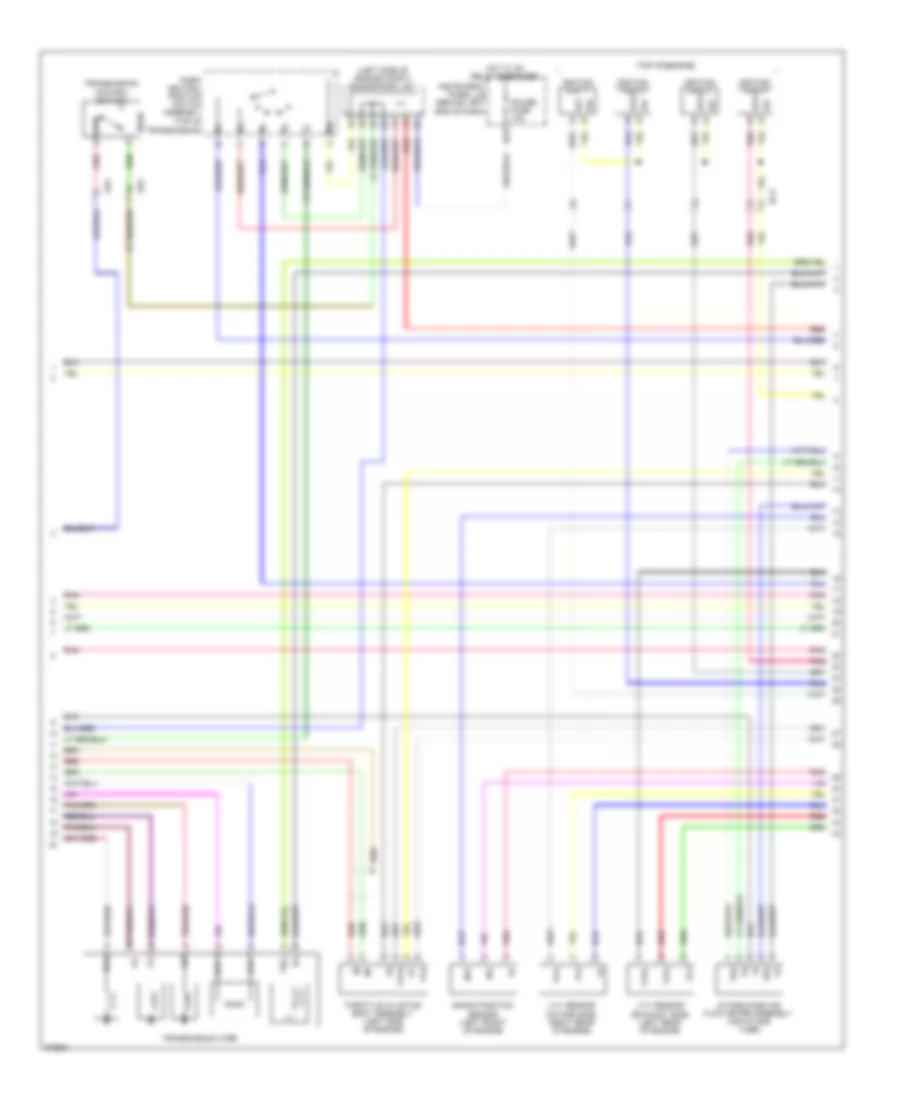
1.3L, Engine Performance Wiring Diagram (3 of 4) for Scion iQ 2014
 https://portal-diagnostov.com/license.html
Automotive Electricians Portal FZCO
Automotive Electricians Portal FZCO
https://portal-diagnostov.com/license.html
https://portal-diagnostov.com/license.html
Automotive Electricians Portal FZCO
Automotive Electricians Portal FZCOList of elements for 1.3L, Engine Performance Wiring Diagram (3 of 4) for Scion iQ 2014:
- (left side of engine compt) engine room j/b 1
- (top of engine)
- Ad2
- Ad4
- At3
- B27
- Bc3
- Crank position sensor (left front of engine)
- Dsl
- E2g
- Gauge fuse 10a
- Hot w/ ig1 relay energized
- Igf
- Ignition coil 1
- Ignition coil 2
- Ignition coil 3
- Ignition coil 4
- Igt
- Igt2
- Igt3
- Igt4
- Instrument panel j/b (behind left end of dash)
- Intake mass air flow meter assembly (air intake tube)
- Ne+
- Ne-
- Nssd
- Park/ neutral position switch assembly (top of
- Pnk
- Red
- Slu+
- Slu-
- Tha
- Tho
- Throttle w/ motor body assembly (left side of engine)
- Transmission control switch
- Transmission wire
- Transmission)
- Vc2
- Vta
- Vta2
- Vve+
- Vve-
- Vvi+
- Vvi-
- Vvt sensor (exhaust side) (left rear of engine)
- Vvt sensor (intake side) (right rear of engine)
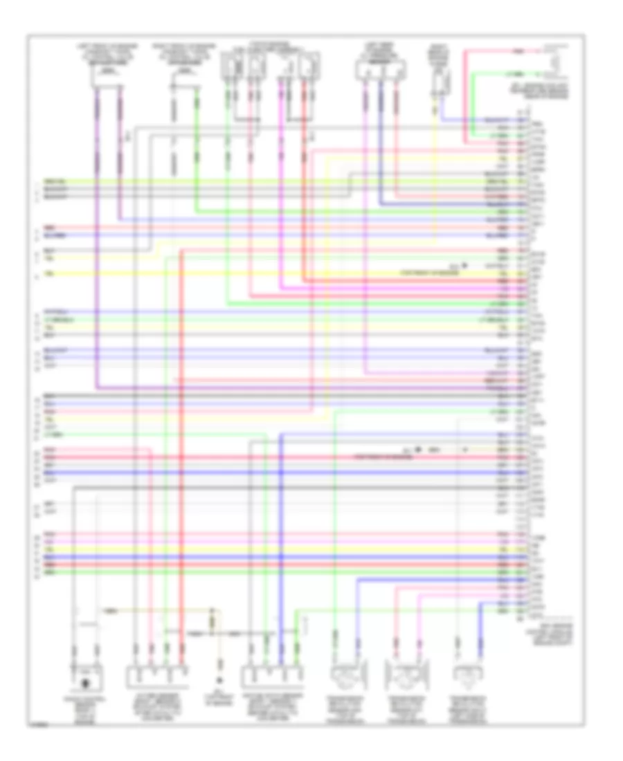
1.3L, Engine Performance Wiring Diagram (4 of 4) for Scion iQ 2014
 https://portal-diagnostov.com/license.html
Automotive Electricians Portal FZCO
Automotive Electricians Portal FZCO
https://portal-diagnostov.com/license.html
https://portal-diagnostov.com/license.html
Automotive Electricians Portal FZCO
Automotive Electricians Portal FZCOList of elements for 1.3L, Engine Performance Wiring Diagram (4 of 4) for Scion iQ 2014:
- (left front of engine) camshaft timing oil control valve (exhaust side)
- (left rear of engine) oil pressure sensor
- (right front of engine) camshaft timing oil control valve (intake side)
- (right rear of engine) purge vsv
- (top of engine) fuel injectors assembly
- 0x1b
- A1a+
- A1a-
- Air fuel ratio sensor (bank 1 sensor 1) (exhaust system, before catalytic converter)
- B11 (top front of engine)
- B12 (top front of engine)
- Bc4
- E.f.i. engine coolant temperature sensor (rear of engine)
- E03
- E2g
- Ecm (engine control module) (left front of engine compt)
- Eknk
- Eppm
- Epto
- Eta
- Etha
- Etho
- Ethw
- Ev1+
- Ev1-
- Ex1b
- G2+
- G2-
- Ha1a
- Ht1b
- Igf1
- Igt1
- Igt2
- Igt3
- Igt4
- Knk1
- Knock control sensor (bank 1) (top of engine)
- Nca
- Ne+
- Ne-
- Nin+
- Nin-
- Notb
- Noto
- Ntb
- Nto
- Oc1+
- Oc1-
- Oe1+
- Oe1-
- Ox1b
- Oxygen sensor (bank 1 sensor 2) (exhaust system, after catalytic converter)
- Pnk
- Ppmp
- Prg
- Pto
- Red
- Tha
- Tho1
- Thw
- Transmission revolution sensor (nin) (top of transmission)
- Transmission revolution sensor (nout) (left side of transmission)
- Transmission revolution sensor (nt) (top of transmission)
- Vce1
- Vcne
- Vcpp
- Vcpt
- Vcta
- Vcv1
- Vta1
- Vta2

 Čeština
 Dansk
Dansk Deutsch
 Ελληνικά
 English
 English
 Español
 Suomi
Suomi Français
 Français
 עברית
עברית Hrvatski
 Magyar
 Italiano
 한국어
한국어 Nederlands
 Polski
 Português
 Português
 Română
 Русский
 Slovenčina
 Slovenščina
 Svenska
 Türkçe
 中文 (中国)
