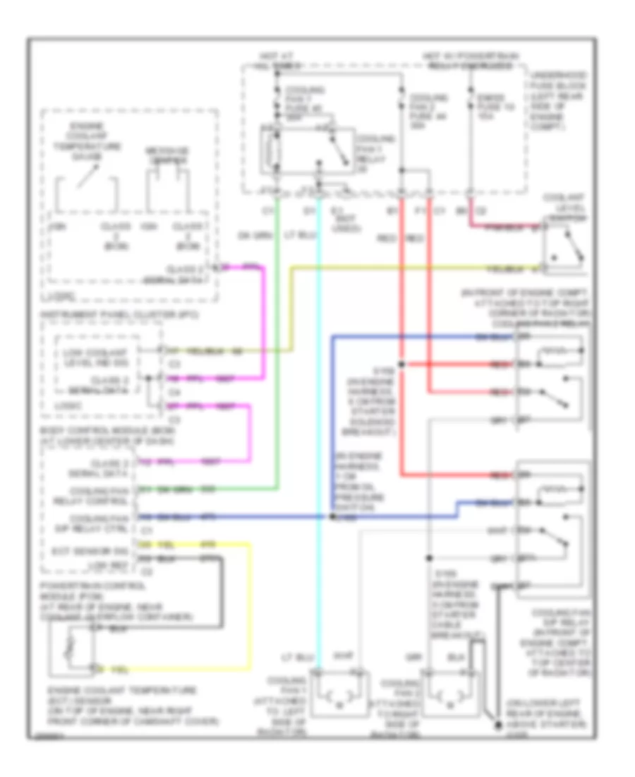
COOLING FAN
Cooling Fan Wiring Diagram for Saturn Ion Red Line 2007
 https://portal-diagnostov.com/license.html
Automotive Electricians Portal FZCO
Automotive Electricians Portal FZCO
https://portal-diagnostov.com/license.html
https://portal-diagnostov.com/license.html
Automotive Electricians Portal FZCO
Automotive Electricians Portal FZCO
List of elements for Cooling Fan Wiring Diagram for Saturn Ion Red Line 2007:
- (in engine harness, 1 cm from oil pressure switch) s160
- (in engine harness, 5 cm from starter cable breakout)
- (in front of engine compt, attached to top right corner of radiator) cooling fan 2 relay
- (on lower left rear of engine, above starter) g105
- 87a
- B6 c2
- Body control module (bcm) (at lower center of dash)
- Class (bcm)
- Class 2 serial data
- Coolant level switch
- Cooling fan 1 (attached to left side of radiator)
- Cooling fan 1 fuse 45 30a
- Cooling fan 1 relay
- Cooling fan 2 (attached to right side of radiator)
- Cooling fan 2 fuse 44 30a
- Cooling fan relay control
- Cooling fan s/p relay (in front of engine compt, attached to top center of radiator)
- Cooling fan s/p relay ctrl
- E1 (not used)
- Ect sensor sig
- Emiss fuse 10 15a
- Engine coolant temperature (ect) sensor (on top of engine, near right front corner of camshaft cover)
- Engine coolant temperature gauge
- F1 c1
- Hot at all times
- Hot w/ powertrain relay energized
- Ign
- Instrument panel cluster (ipc)
- Logic
- Low coolant level ind sig
- Low ref
- Message center
- Powertrain control module (pcm) (at rear of engine, near coolant overflow container)
- Red
- S156
- S158 (in engine harness, 6 cm from starter solenoid breakout)
- Underhood fuse block (left rear side of engine compt)
 Čeština
 Dansk
Dansk Deutsch
 Ελληνικά
 English
 English
 Español
 Suomi
Suomi Français
 Français
 עברית
עברית Hrvatski
 Magyar
 Italiano
 한국어
한국어 Nederlands
 Polski
 Português
 Português
 Română
 Русский
 Slovenčina
 Slovenščina
 Svenska
 Türkçe
 中文 (中国)
 日本語
日本語
