STARTING/CHARGING
2.4L VIN 5
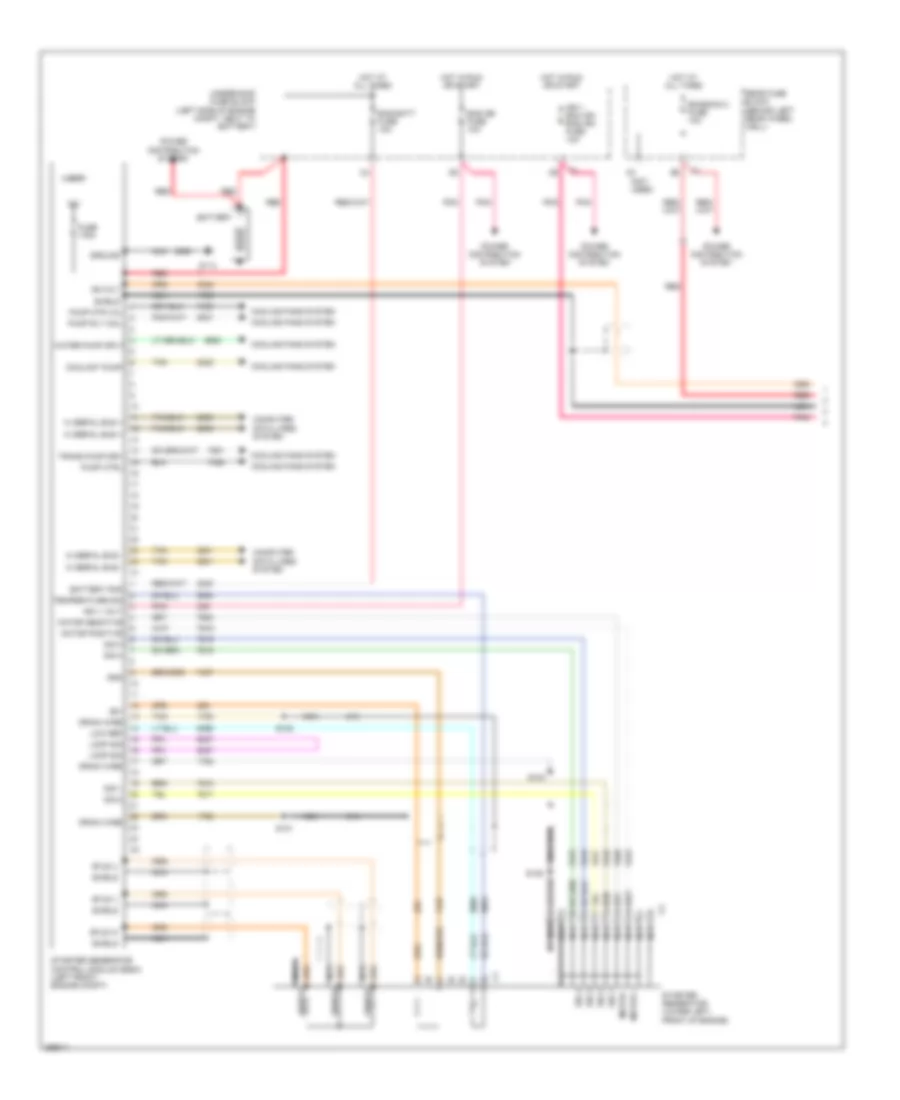
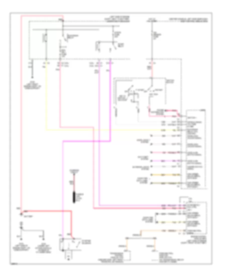
2.4L VIN 5, Hybrid Wiring Diagram (1 of 2) for Saturn Aura Green Line 2007
 https://portal-diagnostov.com/license.html
Automotive Electricians Portal FZCO
Automotive Electricians Portal FZCO
https://portal-diagnostov.com/license.html
https://portal-diagnostov.com/license.html
Automotive Electricians Portal FZCO
Automotive Electricians Portal FZCO
List of elements for 2.4L VIN 5, Hybrid Wiring Diagram (1 of 2) for Saturn Aura Green Line 2007:
- (not used)
- 12v
- 36-volt
- 36v
- Bas batt fuse 10a
- Bas ign fuse 10a
- Battery
- Battery pos
- Computer data lines system
- Coolant pump
- Cooling fans system
- Drain wire
- Emission 2 fuse 10a
- Fuse 175a
- G114
- Gnd
- Ground
- Hi serial bus +
- Hi serial bus -
- Hot at all times
- Hot in run or start
- Ign 1 ecm ign bas ign fuse 10a
- Ign 1 volt
- Logic
- Loop sig
- Low ref
- Motor +
- Motor -
- Motor positive
- Nca
- Pnk
- Power distribution system
- Pump ctrl
- Pump mtr vol
- Pump rly coil
- Rear fuse block (behind left rear wheel well)
- Red
- S101
- S102
- S103
- S105
- Shield
- Sig 1
- Sig 2
- Sig 3
- Sig 4
- Starter generator (lower left, front of engine)
- Starter generator control module (sgcm) (left front engine compt)
- Stud u
- Stud v
- Stud w
- Tan
- Temperature sig
- Trans pump drv
- Underhood fuse block (left side of engine compt, next to battery)
- Water pump sply
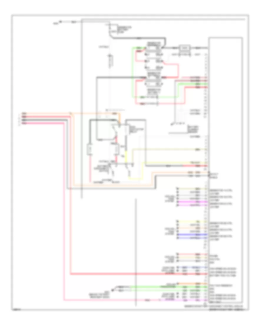
2.4L VIN 5, Hybrid Wiring Diagram (2 of 2) for Saturn Aura Green Line 2007
 https://portal-diagnostov.com/license.html
Automotive Electricians Portal FZCO
Automotive Electricians Portal FZCO
https://portal-diagnostov.com/license.html
https://portal-diagnostov.com/license.html
Automotive Electricians Portal FZCO
Automotive Electricians Portal FZCOList of elements for 2.4L VIN 5, Hybrid Wiring Diagram (2 of 2) for Saturn Aura Green Line 2007:
- 200a
- 36-volt
- Battery current sensor
- Battery disconnect switch
- Battery pos voltage
- Computer data lines system
- Cooling fans system
- Fan ctrl
- Fan tach feedback
- G301 (behind top right rear seat back)
- G402
- Generator 1a ctrl
- Generator 1b ctrl
- Generator 2a ctrl
- Generator 2b ctrl
- Generator 3a ctrl
- Generator 3b ctrl
- Generator battery 1
- Generator battery 2
- Generator battery 3
- Generator battery assembly
- Generator battery disconnect control module
- Generator battery fuse
- Gnd
- High speed gmlan bus+
- High speed gmlan bus-
- Ign 1 volt
- J4xx
- Low ref
- Main contactor relay
- Nca
- Pnk
- Power
- Red
- Shield
- Tan
2.4L VIN 5, Starting Wiring Diagram for Saturn Aura Green Line 2007
 https://portal-diagnostov.com/license.html
Automotive Electricians Portal FZCO
Automotive Electricians Portal FZCO
https://portal-diagnostov.com/license.html
https://portal-diagnostov.com/license.html
Automotive Electricians Portal FZCO
Automotive Electricians Portal FZCOList of elements for 2.4L VIN 5, Starting Wiring Diagram for Saturn Aura Green Line 2007:
- (center console, left side near dash)
- (left side of engine compt, next to battery)
- 5-volt ref
- Acc
- Battery
- Battery current sensor
- Body control module (bcm)
- C1 c2
- C10
- Computer data lines system
- Current sens isg
- Current sensor sig
- D1 c4
- D12 c1
- Door lock/ unlock sig
- Door locks system
- Ecm ign 1 fuse 10a
- Engine control module (ecm) (left side of engine compt, behind battery)
- Exterior lights system
- G104 (left side of engine compt, on core support)
- G105 (under left intake manifold, on rear of cylinder head)
- G109 (left front engine compt, on core support)
- Hazard switch sig
- High speed gmlan serial data bus +
- High speed gmlan serial data bus -
- Hot at all times
- Ign 1
- Ign sensor fuse 2a
- Ignition 1
- Ignition switch
- Key in ignition switch
- Logic
- Low ref
- Off
- Off/run crank voltage 5v ref
- Park/neutral position (pnp) switch (on transmission, below master cylinder)
- Park/neutral sig
- Pnk
- Power distribution system
- Red
- Run
- Run/crank relay
- Run/crank relay coil control
- Start
- Start relay
- Starter rly coil ctrl
- Starter solenoid
- Strtr fuse 30a
- Tan
- Underhood fuse block
3.5L VIN N
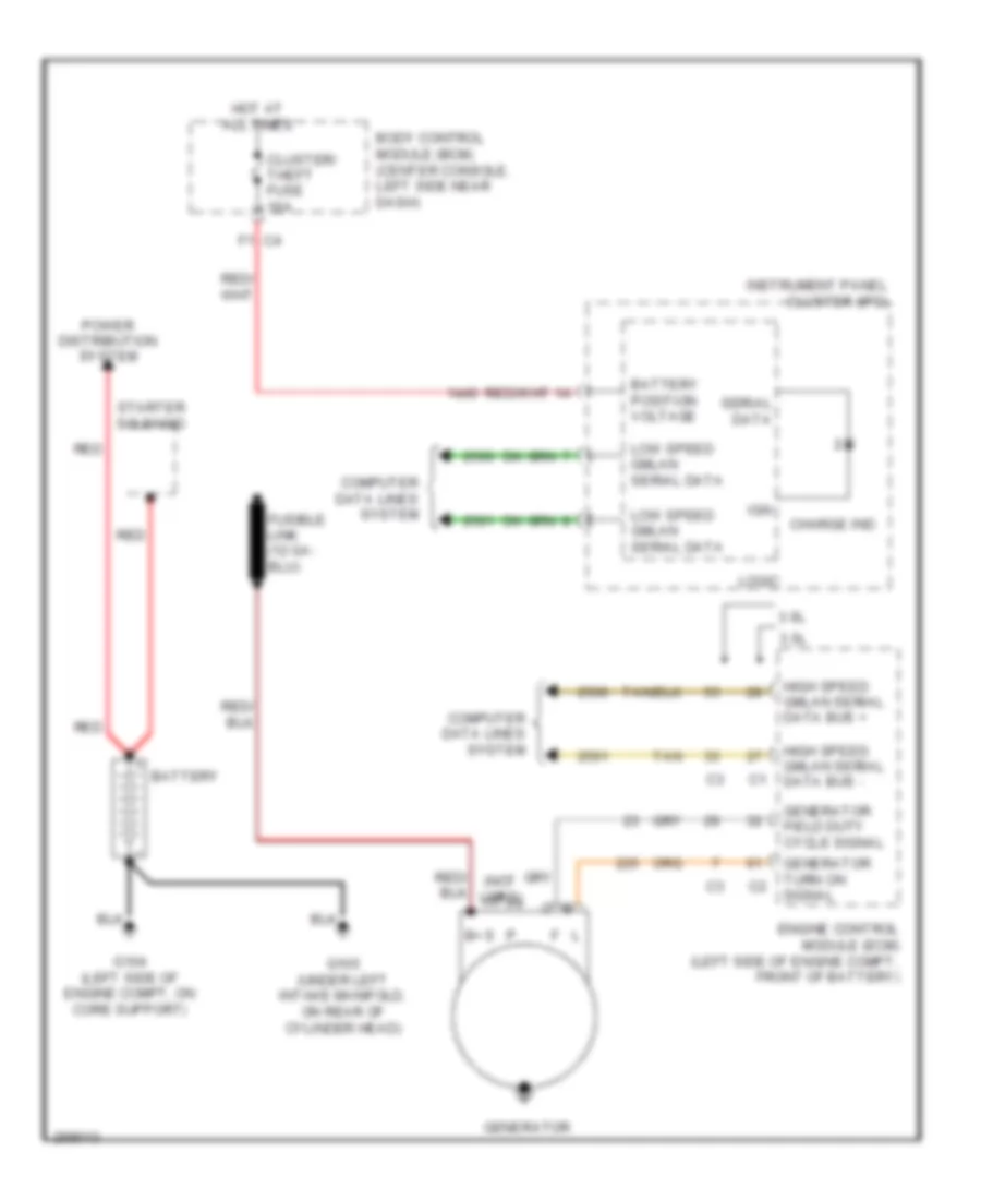
3.5L VIN N, Charging Wiring Diagram for Saturn Aura Green Line 2007
 https://portal-diagnostov.com/license.html
Automotive Electricians Portal FZCO
Automotive Electricians Portal FZCO
https://portal-diagnostov.com/license.html
https://portal-diagnostov.com/license.html
Automotive Electricians Portal FZCO
Automotive Electricians Portal FZCOList of elements for 3.5L VIN N, Charging Wiring Diagram for Saturn Aura Green Line 2007:
- (not used)
- 3.5l
- 3.6l
- B+ s
- Battery
- Battery position voltage
- Body control module (bcm) (center console, left side near dash)
- Charge ind
- Cluster/ theft fuse 10a
- Computer data lines system
- Engine control module (ecm) (left side of engine compt, front of battery)
- F1 c4
- G104 (left side of engine compt, on core support)
- G105 (under left intake manifold, on rear of cylinder head)
- Generator
- Generator field duty cycle signal
- Generator turn on signal
- High speed gmlan serial data bus +
- High speed gmlan serial data bus -
- Hot at all times
- Ign
- Instrument panel cluster (ipc)
- Logic
- Low speed gmlan serial data
- Power distribution system
- Red
- Serial data
- Starter solenoid
- Tan
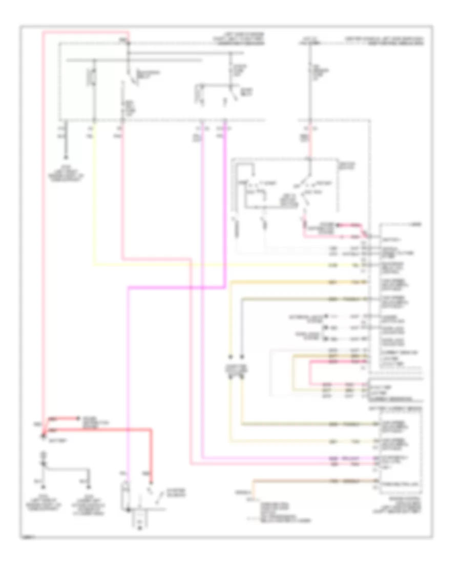
3.5L VIN N, Starting Wiring Diagram for Saturn Aura Green Line 2007
 https://portal-diagnostov.com/license.html
Automotive Electricians Portal FZCO
Automotive Electricians Portal FZCO
https://portal-diagnostov.com/license.html
https://portal-diagnostov.com/license.html
Automotive Electricians Portal FZCO
Automotive Electricians Portal FZCOList of elements for 3.5L VIN N, Starting Wiring Diagram for Saturn Aura Green Line 2007:
- (3.5l)
- (3.6l)
- (center console, left side near dash)
- (left side of engine compt, next to battery)
- 3.5l
- 3.6l
- 5v ref
- A3 c2
- Acc
- Anti-theft system
- Battery
- Body control module (bcm)
- C1 d8
- C10
- C2 f6
- Charging circuit
- Computer data lines system
- D1 c4
- D12 c1
- Door locks system
- Door/lock/ unlock signal
- E12 c1
- Ecm ign 1 fuse 10a
- Engine control module (ecm) (left side of engine compt, front of battery)
- Exterior lights system
- G104 (left side of engine compt, on core support)
- G105 (under left intake manifold, on rear of cylinder head)
- G109 (left front engine compt, on core support)
- Hazard switch signal
- High speed gmlan serial data bus +
- High speed gmlan serial data bus -
- Hood ajar switch signal
- Hot at all times
- Ign 1
- Ign sensor fuse 2a
- Ignition 1
- Ignition switch
- Key in ignition switch
- Logic
- Off
- Off/run crank voltage
- Park/neutral position (pnp) switch (on transmission, below master cylinder)
- Park/neutral signal
- Pnk
- Power distribution system
- Red
- Run
- Run/crank relay
- Run/crank relay coil control
- Start
- Start relay
- Starter rly coil ctrl
- Starter solenoid
- Strtr fuse 30a
- Tan
- Transmission control module (tcm) (inboard side, left front frame rail extension)
- Underhood fuse block
3.6L VIN 7
3.6L VIN 7, Charging Wiring Diagram for Saturn Aura Green Line 2007
 https://portal-diagnostov.com/license.html
Automotive Electricians Portal FZCO
Automotive Electricians Portal FZCO
https://portal-diagnostov.com/license.html
https://portal-diagnostov.com/license.html
Automotive Electricians Portal FZCO
Automotive Electricians Portal FZCOList of elements for 3.6L VIN 7, Charging Wiring Diagram for Saturn Aura Green Line 2007:
- (not used)
- 3.5l
- 3.6l
- B+ s
- Battery
- Battery position voltage
- Body control module (bcm) (center console, left side near dash)
- Charge ind
- Cluster/ theft fuse 10a
- Computer data lines system
- Engine control module (ecm) (left side of engine compt, front of battery)
- F1 c4
- G104 (left side of engine compt, on core support)
- G105 (under left intake manifold, on rear of cylinder head)
- Generator
- Generator field duty cycle signal
- Generator turn on signal
- High speed gmlan serial data bus +
- High speed gmlan serial data bus -
- Hot at all times
- Ign
- Instrument panel cluster (ipc)
- Logic
- Low speed gmlan serial data
- Power distribution system
- Red
- Serial data
- Starter solenoid
- Tan
3.6L VIN 7, Starting Wiring Diagram for Saturn Aura Green Line 2007
 https://portal-diagnostov.com/license.html
Automotive Electricians Portal FZCO
Automotive Electricians Portal FZCO
https://portal-diagnostov.com/license.html
https://portal-diagnostov.com/license.html
Automotive Electricians Portal FZCO
Automotive Electricians Portal FZCOList of elements for 3.6L VIN 7, Starting Wiring Diagram for Saturn Aura Green Line 2007:
- (3.5l)
- (3.6l)
- (center console, left side near dash)
- (left side of engine compt, next to battery)
- 3.5l
- 3.6l
- 5v ref
- A3 c2
- Acc
- Anti-theft system
- Battery
- Body control module (bcm)
- C1 d8
- C10
- C2 f6
- Charging circuit
- Computer data lines system
- D1 c4
- D12 c1
- Door locks system
- Door/lock/ unlock signal
- E12 c1
- Ecm ign 1 fuse 10a
- Engine control module (ecm) (left side of engine compt, front of battery)
- Exterior lights system
- G104 (left side of engine compt, on core support)
- G105 (under left intake manifold, on rear of cylinder head)
- G109 (left front engine compt, on core support)
- Hazard switch signal
- High speed gmlan serial data bus +
- High speed gmlan serial data bus -
- Hood ajar switch signal
- Hot at all times
- Ign 1
- Ign sensor fuse 2a
- Ignition 1
- Ignition switch
- Key in ignition switch
- Logic
- Off
- Off/run crank voltage
- Park/neutral position (pnp) switch (on transmission, below master cylinder)
- Park/neutral signal
- Pnk
- Power distribution system
- Red
- Run
- Run/crank relay
- Run/crank relay coil control
- Start
- Start relay
- Starter rly coil ctrl
- Starter solenoid
- Strtr fuse 30a
- Tan
- Transmission control module (tcm) (inboard side, left front frame rail extension)
- Underhood fuse block

 Čeština
 Dansk
Dansk Deutsch
 Ελληνικά
 English
 English
 Español
 Suomi
Suomi Français
 Français
 עברית
עברית Hrvatski
 Magyar
 Italiano
 한국어
한국어 Nederlands
 Polski
 Português
 Português
 Română
 Русский
 Slovenčina
 Slovenščina
 Svenska
 Türkçe
 中文 (中国)
