ANTI-LOCK BRAKES
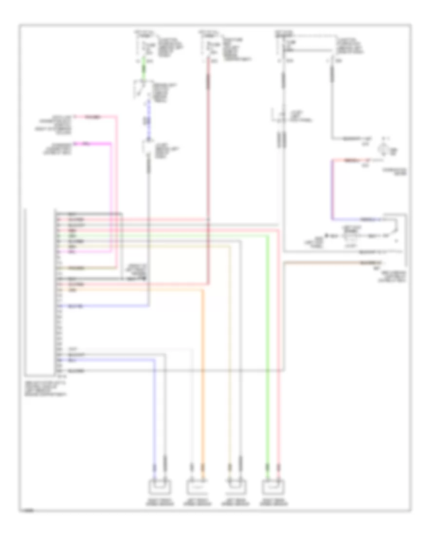
Anti-lock Brake Wiring Diagrams for Suzuki Esteem GL 2001
 https://portal-diagnostov.com/license.html
Automotive Electricians Portal FZCO
Automotive Electricians Portal FZCO
https://portal-diagnostov.com/license.html
https://portal-diagnostov.com/license.html
Automotive Electricians Portal FZCO
Automotive Electricians Portal FZCO
List of elements for Anti-lock Brake Wiring Diagrams for Suzuki Esteem GL 2001:
- (front of left front fender) g100
- (left kick panel)
- Abs actuator unit & control module (left rear of engine compartment)
- Abs ind
- Abs warning lamp relay (on relay box)
- Brakelight switch (above brake pedal)
- Combination meter
- Data link connector (dlc) (partial) (right of steering column)
- Diagnosis connector 2 (on relay box)
- E116
- E16
- E18
- E67
- E70
- Fuse 20a
- Fuse 60a
- G18
- G19
- G200 (left kick panel)
- G28
- Hot at all times
- Hot in on or start
- J/c e07 (behind left side of dash)
- J/c e71
- J/c e71 (left kick panel)
- Junction fuse block (behind left side of dash)
- Left front speed sensor
- Left rear speed sensor
- Main fuse box (on left side of engine compartment)
- Red
- Right front speed sensor
- Right rear speed sensor
 Čeština
 Dansk
Dansk Deutsch
 Ελληνικά
 English
 English
 Español
 Suomi
Suomi Français
 Français
 עברית
עברית Hrvatski
 Magyar
 Italiano
 한국어
한국어 Nederlands
 Polski
 Português
 Português
 Română
 Русский
 Slovenčina
 Slovenščina
 Svenska
 Türkçe
 中文 (中国)
 日本語
日本語
