ENGINE PERFORMANCE
3.0L
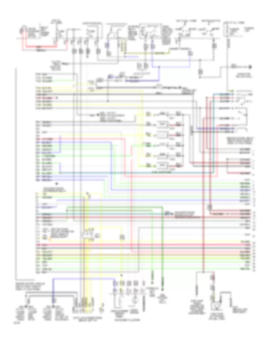
3.0L, Engine Performance Wiring Diagrams (1 of 2) for Mitsubishi Montero LS 1994
 https://portal-diagnostov.com/license.html
Automotive Electricians Portal FZCO
Automotive Electricians Portal FZCO
https://portal-diagnostov.com/license.html
https://portal-diagnostov.com/license.html
Automotive Electricians Portal FZCO
Automotive Electricians Portal FZCO
List of elements for 3.0L, Engine Performance Wiring Diagrams (1 of 2) for Mitsubishi Montero LS 1994:
- air conditioning compressor relay
- (w/ a/t)
- (w/ m/t)
- A09x
- Abs control unit pin 12
- Acc
- Air conditioning engine coolant temperature switch
- C04
- C06
- C101
- C11
- C12
- C56
- C62-3
- C81
- C82
- C94
- C96
- C99
- Capacitor (no loc avail)
- Check engine
- Clutch pedal position switch
- Dash, at kick panel)
- Data link connector(s) (below left i/p)
- Engine control module (below right side of
- Engine control relay (below right side of dash, at kick panel)
- Fuel injectors
- Fuel pump (in top side of fuel tank)
- Fuel pump check connector (right rear of engine compartment)
- Fuse 10a
- Fusible link
- Fusible link 6 20a
- G201 (right of glove box)
- G201 (w/ m/t) (right side of i/p, left of glove box)
- G202 (lower left side of i/p)
- G202 (w/ m/t) (lower left side of i/p)
- G203 (right kick panel)
- G312 (behind left rear seat)
- Hot at all times
- Hydraulic unit pin 1 (abs)
- Ignition switch
- Ignition timing adjust connector (right rear of engine compt)
- Instrument cluster
- Iod or storage conn- ector
- J/c 1 c62-1
- J/c 2 c62-2
- J/c 3
- Junction block
- Lock
- No.1
- No.2
- No.3
- No.4
- No.5
- No.6
- Park/ neutral position switch (right side of engine compt)
- Pnk
- Red
- Relay box: engine compt
- Start
- Starter relay (behind center dash panel)
- Tachometer
- Vehicle speed sensor (reed)
- W/ a/t
- W/ a/t w/ m/t
- W/ m/t
- With a/t
- With m/t
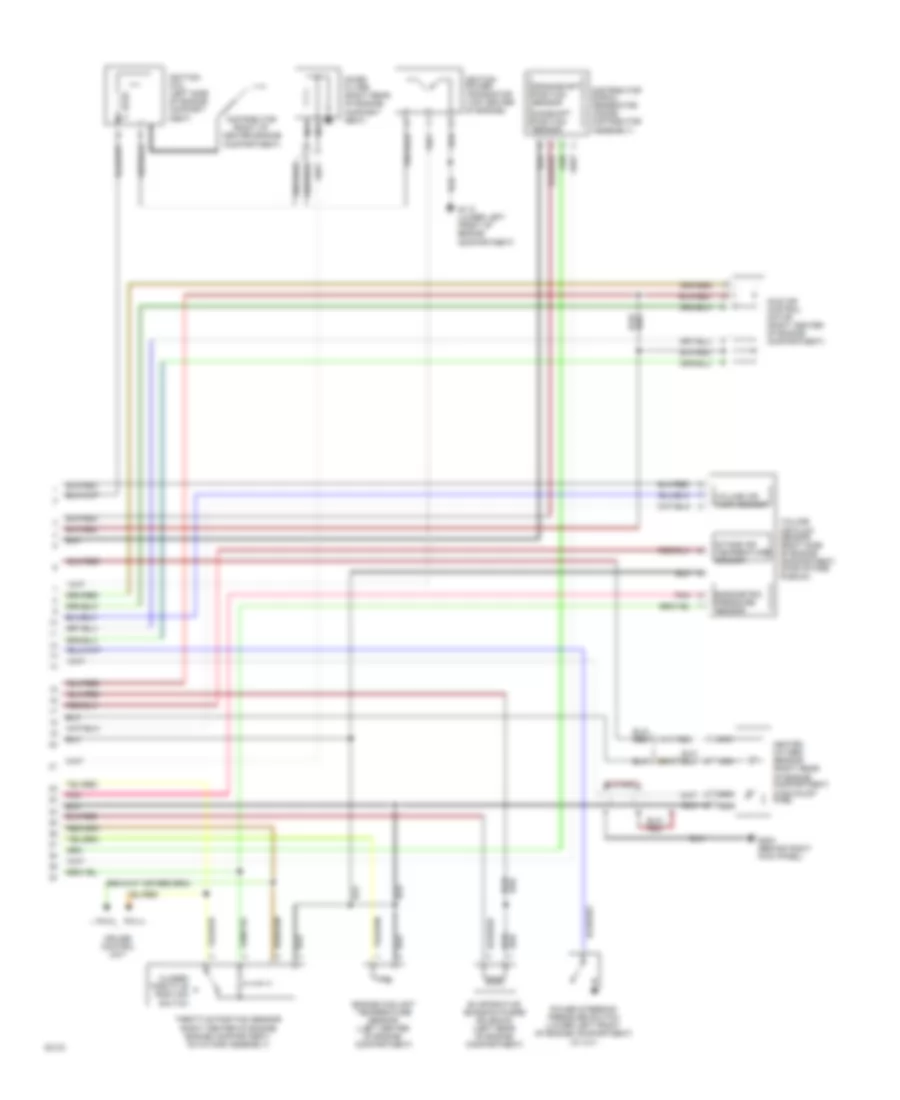
3.0L, Engine Performance Wiring Diagrams (2 of 2) for Mitsubishi Montero LS 1994
 https://portal-diagnostov.com/license.html
Automotive Electricians Portal FZCO
Automotive Electricians Portal FZCO
https://portal-diagnostov.com/license.html
https://portal-diagnostov.com/license.html
Automotive Electricians Portal FZCO
Automotive Electricians Portal FZCOList of elements for 3.0L, Engine Performance Wiring Diagrams (2 of 2) for Mitsubishi Montero LS 1994:
- Barometric pressure sensor
- Camshaft position sensor
- Closed throttle position switch
- Crankshaft position sensor
- Cruise control unit
- Distributor (right of center engine compartment)
- Distributor signal generator (inside distributor assembly)
- Engine coolant temperature sensor (left center of engine compartment)
- Evaporative emission purge solenoid (left rear of engine compartment)
- G110 (lower left front of engine compartmemt)
- G203 (behind right kick panel)
- Heated oxygen sensor (right rear of engine compartment, in exhaust pipe)
- Idle air control motor (right center of engine compartment)
- Ignition coil (left side of engine compart-
- Ignition power transistor (top center of engine)
- Intake air temperature sensor
- Ment)
- Nca
- Noise filter (right rear of engine) compart- ment)
- Pin 4
- Pin 5
- Pnk
- Power steering pressure switch (lower left front of engine compartment) (w/ a/t)
- Throttle position sensor (right center of engine engine compartment, on intake assembly)
- Volume air flow sensor
- Volume air flow sensor (right side of engine compartment, in air intake plenum)
3.5L
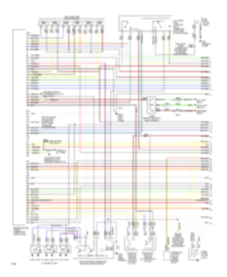
3.5L, Engine Performance Wiring Diagrams (1 of 2) for Mitsubishi Montero LS 1994
 https://portal-diagnostov.com/license.html
Automotive Electricians Portal FZCO
Automotive Electricians Portal FZCO
https://portal-diagnostov.com/license.html
https://portal-diagnostov.com/license.html
Automotive Electricians Portal FZCO
Automotive Electricians Portal FZCOList of elements for 3.5L, Engine Performance Wiring Diagrams (1 of 2) for Mitsubishi Montero LS 1994:
- (abs)
- A42
- A42-1
- Abs control unit pin 12
- Air conditioning compressor clutch relay pin 2
- Air conditioning engine coolant temperature switch
- C36
- C37
- C38
- C62-1
- C62-2
- C62-3
- C66-1
- Camshaft position sensor (at right camshaft pulley)
- Crankshaft position sensor (at crankshaft pulley)
- Defogger relay
- Diode (behind center of dash console)
- Engine control module (under right side of dash)
- Fuel injectors (top of engine)
- Fuel pump (in fuel tank)
- Fuel pump check connector (center rear of engine compartment)
- G102 (left inner fender)
- G203 (right kick panel)
- G407 (beneath floor)
- Hydraulic unit
- Ignition power transistor (center of engine compt)
- Ignition timing adjustment connector (right rear of engine compartment)
- J/c 1
- J/c 2
- J/c 3
- Multiport fuel injection relay (under far right side of dash panel)
- Nca
- Noise filter (no loc avail)
- Pnk
- Red
- Solid state
- Stop light switch
- Tail light relay
- To spark plugs
- Transaxle control module (under center of i/p)
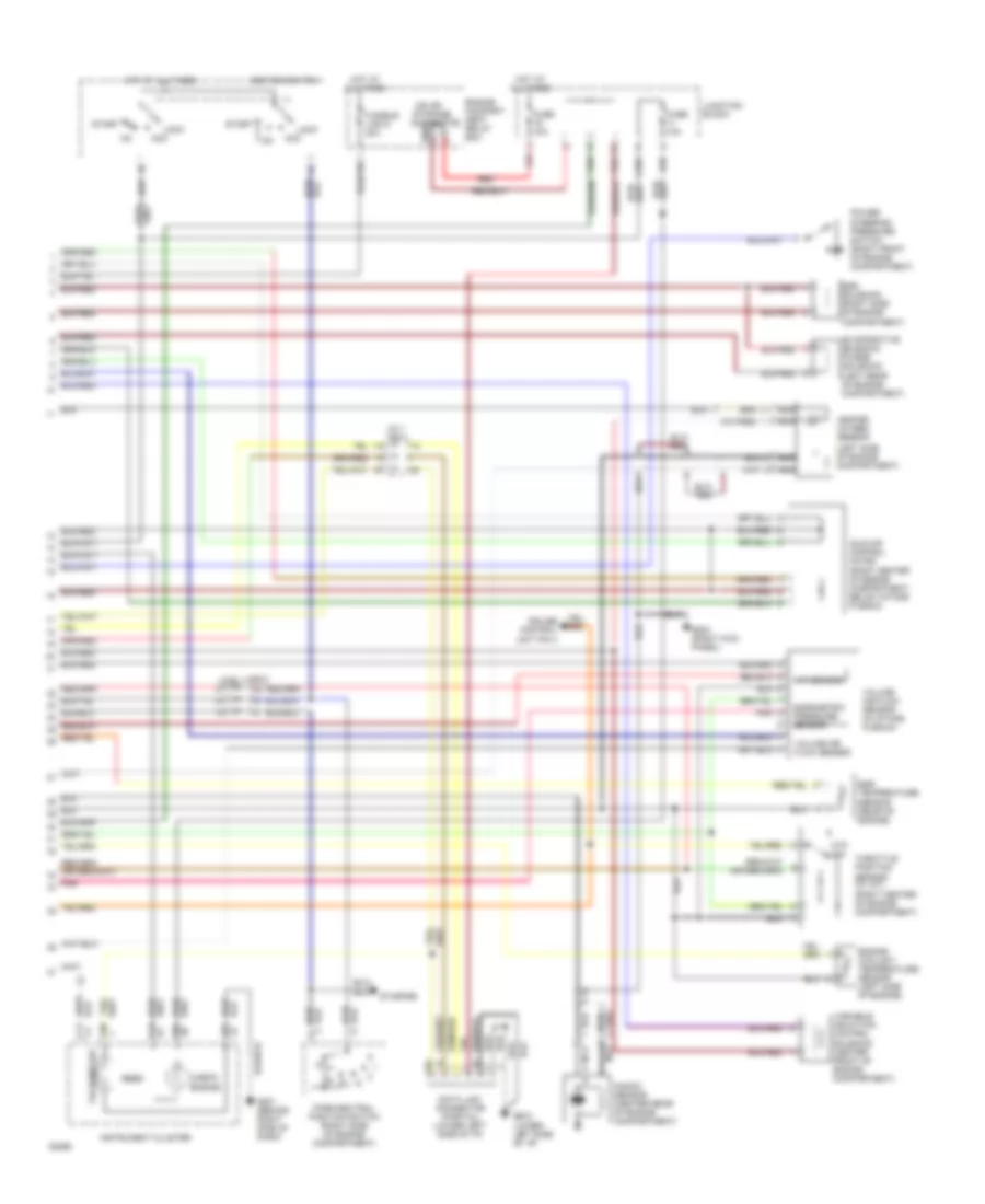
3.5L, Engine Performance Wiring Diagrams (2 of 2) for Mitsubishi Montero LS 1994
 https://portal-diagnostov.com/license.html
Automotive Electricians Portal FZCO
Automotive Electricians Portal FZCO
https://portal-diagnostov.com/license.html
https://portal-diagnostov.com/license.html
Automotive Electricians Portal FZCO
Automotive Electricians Portal FZCOList of elements for 3.5L, Engine Performance Wiring Diagrams (2 of 2) for Mitsubishi Montero LS 1994:
- iod or storage connector
- (left side of engine compartment)
- A09x
- Acc
- Barometric pressure sensor
- C04
- C06
- C101
- C11
- C12
- C56
- C62-2
- C81
- C94
- C96
- C99
- Check engine
- Cruise control unit pin 4
- Ctp sw
- Data link connector (partial) (lower left side of i/p)
- Egr solenoid (right side of engine compartment)
- Egr temperature sensor (rear of engine)
- Engine compart- ment relay box
- Engine coolant temperature sensor (left side of engine)
- Evaporative emission purge solenoid (left rear of engine compartment)
- Fuse 10a
- Fusible link 6 20a
- G201 (behind right side of dash)
- G202 (lower left side of i/p)
- G203 (right kick panel)
- Heated oxygen sensor
- Hot at all times
- Iat sensor
- Idle air control motor (right center of engine compartment, below intake plenum)
- Ignition switch
- Instrument cluster
- J/c 1 c62-1
- J/c 2
- Junction block
- Knock sensor (center rear of engine compartment)
- Lock
- Nca
- Park/neutral position switch (right side of engine compartment)
- Pnk
- Power steering pressure switch (right front of engine compartment)
- Red
- Reed
- Start
- Starter
- Tachometer
- Throttle position sensor (w/ a/t) (right center of engine compartment)
- Variable induction control solenoid (center front of engine compartment)
- Volume air flow sensor
- Volume air flow sensor (in intake plenum)

 Čeština
 Dansk
Dansk Deutsch
 Ελληνικά
 English
 English
 Español
 Suomi
Suomi Français
 Français
 עברית
עברית Hrvatski
 Magyar
 Italiano
 한국어
한국어 Nederlands
 Polski
 Português
 Português
 Română
 Русский
 Slovenčina
 Slovenščina
 Svenska
 Türkçe
 中文 (中国)
