POWER DISTRIBUTION
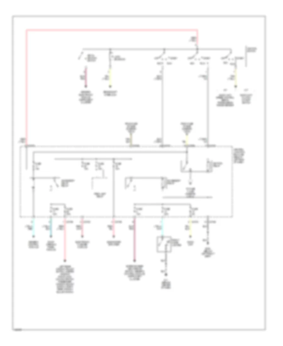
Power Distribution Wiring Diagram (1 of 3) for Mazda Tribute ES 2002
 https://portal-diagnostov.com/license.html
Automotive Electricians Portal FZCO
Automotive Electricians Portal FZCO
https://portal-diagnostov.com/license.html
https://portal-diagnostov.com/license.html
Automotive Electricians Portal FZCO
Automotive Electricians Portal FZCO
List of elements for Power Distribution Wiring Diagram (1 of 3) for Mazda Tribute ES 2002:
- (left front corner of engine compt) battery junction box
- A/c clutch relay
- Abs control module, abs test connector
- Audio unit, data link connector, generic electronic module, instrument cluster
- Battery
- Battery junction box (bjb) (left front corner of engine compt)
- Blower motor relay
- Brake pedal position switch, deactivator switch
- C270b
- C270d
- C270e
- Central junction box (cjb) (below left end of dash)
- Daytime running lamps module, daytime running lamps relay
- Driver seat adjust switch, generic electronic module
- Fog lamp relay
- From fuse 19 (bjb) (diagram 1 of 3)
- Fuel pump relay
- Fuse 10a
- Fuse 15a
- Fuse 20a
- Fuse 25a
- Fuse 30a
- Fuse 40a
- Fuse 40a (2.0l)
- Fuse 50a (3.0l)
- Fuse 5a
- Fuse 60a
- Fuse fb 120a
- G11 (behind center of dash)
- G20 (left rear side of cargo compt)
- Generator
- Headlamp relay
- High speed fan control relay 1
- High speed fan control relay 2
- Horn relay
- Low speed fan control relay
- Low speed fan control relay, medium speed fan control relay
- Pcm power relay
- Power point
- Powertrain control module
- Rear defrost relay
- Rear power point
- Red
- Starter motor
- Starter relay
- To accessory relay (diagram 2 of 3)
- To fuse 24 (bjb) (diagram 1 of 3)
- To ignition relay (diagram 2 of 3)
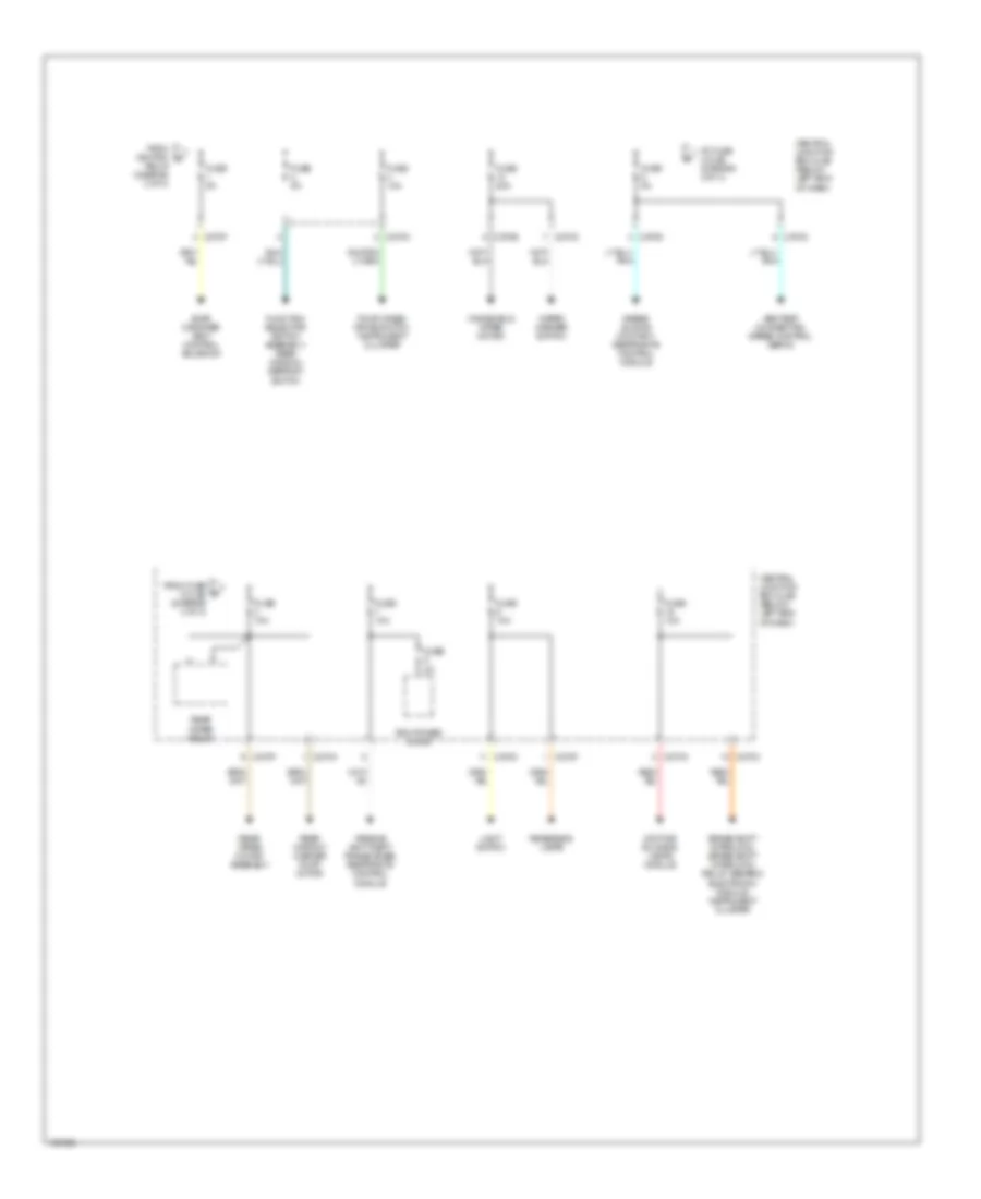
Power Distribution Wiring Diagram (2 of 3) for Mazda Tribute ES 2002
 https://portal-diagnostov.com/license.html
Automotive Electricians Portal FZCO
Automotive Electricians Portal FZCO
https://portal-diagnostov.com/license.html
https://portal-diagnostov.com/license.html
Automotive Electricians Portal FZCO
Automotive Electricians Portal FZCOList of elements for Power Distribution Wiring Diagram (2 of 3) for Mazda Tribute ES 2002:
- A/t
- Acc
- Accessory delay relay
- Accessory relay
- Audio unit
- Audio unit, clutch cutoff switch
- Audio unit. speed control servo, transmission range sensor
- Brake shift interlock
- C270b
- C270c
- C270d
- C270e
- Central junction box (cjb) (below left end of dash)
- Electronic flasher module
- Exterior rear view mirror switch, generic control module, instrument cluster
- From fuse 19 (bjb) (diagram 1 of 3) b
- From fuse 20 (bjb) (diagram 1 of 3) c
- Front cigar lighter
- Fuse 10a
- Fuse 15a
- Fuse 20a
- Fuse 30a
- Fuse 5a
- G11 (behind center of dash)
- G300 (below left front seat)
- Generic control module
- Generic electronic module, instrument cluster
- Ignition relay
- Ignition switch
- Key in ignition switch
- Left rear window adjust switch, master window/ door lock/ unlock switch, passenger window adjust switch, right rear window adjust switch
- Lock solenoid
- M/t
- Off
- Park lamp relay
- Roof opening panel module
- Run
- Start
- Subwoofer amplifier
- To fuse 1 (cjb) (diagram 3 of 3)
Power Distribution Wiring Diagram (3 of 3) for Mazda Tribute ES 2002
 https://portal-diagnostov.com/license.html
Automotive Electricians Portal FZCO
Automotive Electricians Portal FZCO
https://portal-diagnostov.com/license.html
https://portal-diagnostov.com/license.html
Automotive Electricians Portal FZCO
Automotive Electricians Portal FZCOList of elements for Power Distribution Wiring Diagram (3 of 3) for Mazda Tribute ES 2002:
- Abs test connector, speed control servo
- Airbag sliding contact, restraints control module
- Brake shift interlock, brake shift interlock relay, generic electronic module, instrument cluster
- C270a
- C270b
- C270c
- C270d
- C270f
- Central junction box (cjb) (below left end of dash)
- Daytime running lamps module
- Evap canister vent control solenoid
- Four wheel drive switch, instrument cluster
- From fuse 5 (cjb) (diagram 3 of 3)
- From ignition d
- Function selector switch assembly, rear window defrost switch
- Fuse 10a
- Fuse 20a
- Fuse 3a
- Fuse 5a
- Light switch
- Passive anti-theft transceiver, restraints control module
- Pcm power diode
- Rear window washer pump motor
- Rear wiper motor assembly
- Rear wiper relay
- Relay (diagram 2 of 3)
- Reversing lamps
- To fuse 3 (cjb) (diagram 3 of 3)
- Windshield wiper motor
- Wiper/ washer switch

 Čeština
 Dansk
Dansk Deutsch
 Ελληνικά
 English
 English
 Español
 Suomi
Suomi Français
 Français
 עברית
עברית Hrvatski
 Magyar
 Italiano
 한국어
한국어 Nederlands
 Polski
 Português
 Português
 Română
 Русский
 Slovenčina
 Slovenščina
 Svenska
 Türkçe
 中文 (中国)
