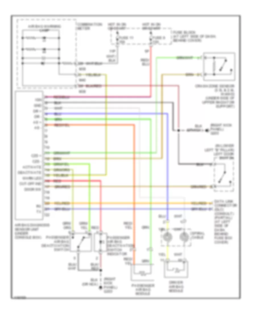
SUPPLEMENTAL RESTRAINTS
Supplemental Restraint Wiring Diagram for Nissan Frontier XE 1999
 https://portal-diagnostov.com/license.html
Automotive Electricians Portal FZCO
Automotive Electricians Portal FZCO
https://portal-diagnostov.com/license.html
https://portal-diagnostov.com/license.html
Automotive Electricians Portal FZCO
Automotive Electricians Portal FZCO
List of elements for Supplemental Restraint Wiring Diagram for Nissan Frontier XE 1999:
- (in lower left "b" pillar) left door switch
- (right kick panel) g203
- 11p
- Activate
- Air bag diagnosis sensor unit (under console box)
- Air bag warning lamp
- As +
- As -
- Combination meter
- Crash zone sensor (3.3l & 2.4l w/4wd) (under side of upper radiator support)
- Cut-off ind
- Czs +
- Czs -
- Data link connector (dlc) (consult) (partial) (at left side of dash, behind fuse box cover)
- Deactivate
- Door sw
- Dr +
- Dr -
- Driver air bag module
- Fuse 11 10a
- Fuse 9 10a
- Fuse block (at left side of dash, behind cover)
- Gnd
- Hot in on or start
- Ign
- M38
- M39
- M40
- Passenger air bag deactivation switch
- Passenger air bag deactivation switch indicator
- Passenger air bag module
- Red
- Spiral cable
- Warn led
 Čeština
 Dansk
Dansk Deutsch
 Ελληνικά
 English
 English
 Español
 Suomi
Suomi Français
 Français
 עברית
עברית Hrvatski
 Magyar
 Italiano
 한국어
한국어 Nederlands
 Polski
 Português
 Português
 Română
 Русский
 Slovenčina
 Slovenščina
 Svenska
 Türkçe
 中文 (中国)
 日本語
日本語
