ANTI-LOCK BRAKES
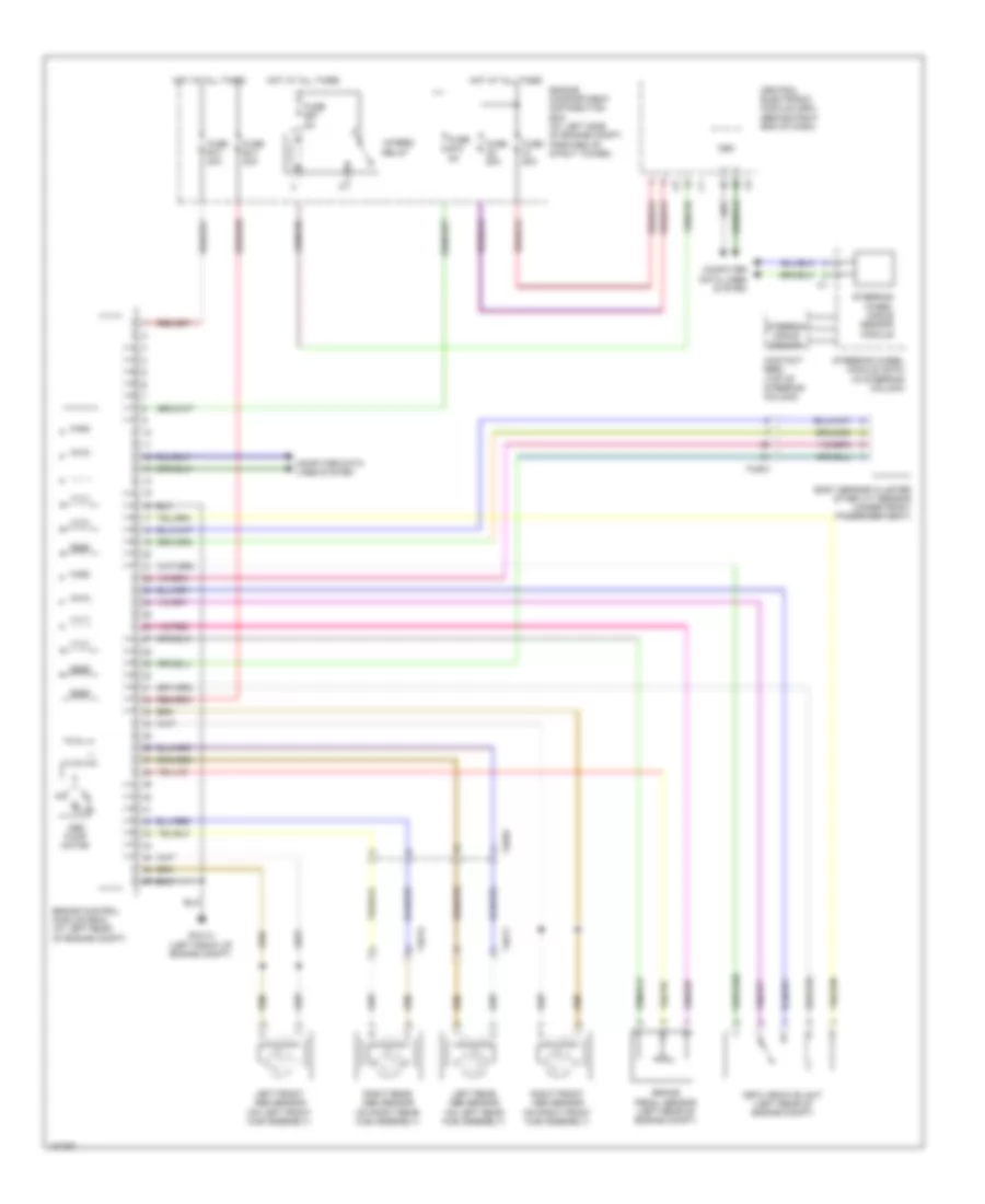
Anti-lock Brakes Wiring Diagram for Volvo S80 T-6 2013
 https://portal-diagnostov.com/license.html
Automotive Electricians Portal FZCO
Automotive Electricians Portal FZCO
https://portal-diagnostov.com/license.html
https://portal-diagnostov.com/license.html
Automotive Electricians Portal FZCO
Automotive Electricians Portal FZCO
List of elements for Anti-lock Brakes Wiring Diagram for Volvo S80 T-6 2013:
- 15-feed relay
- 74/504
- 74/511
- 74/512
- Abs pump motor
- Body sensor cluster stability sensor (under front passenger seat)
- Brake control module (bcm) (at left rear of engine compt)
- Brake pedal sensor (left rear of engine compt)
- Cem
- Central electronic module (cem) (behind right end of dash)
- Computer data lines system
- Contact reel (top of steering column)
- Dstc archive unit (left rear of engine compt)
- Engine compartment distribution box (at left side of engine compt, forward of strut tower)
- Fuse a1 50a
- Fuse a2 50a
- Fuse b13 40a
- Fuse b14 20a
- Fuse b18 5a
- Fuse b27 5a
- Gxx14 (left front of engine compt)
- Hot at all times
- Left front abs sensor (on left front hub assembly)
- Left rear abs sensor (on left rear hub assembly)
- Right front abs sensor (on right front hub assembly)
- Right rear abs sensor (on right rear hub assembly)
- Steering angle sensor
- Steering wheel angle sensor module
- Steering wheel module (swm) (in steering column)
 Čeština
 Dansk
Dansk Deutsch
 Ελληνικά
 English
 English
 Español
 Suomi
Suomi Français
 Français
 עברית
עברית Hrvatski
 Magyar
 Italiano
 한국어
한국어 Nederlands
 Polski
 Português
 Português
 Română
 Русский
 Slovenčina
 Slovenščina
 Svenska
 Türkçe
 中文 (中国)
 日本語
日本語
