Навигация GPS Парктроники
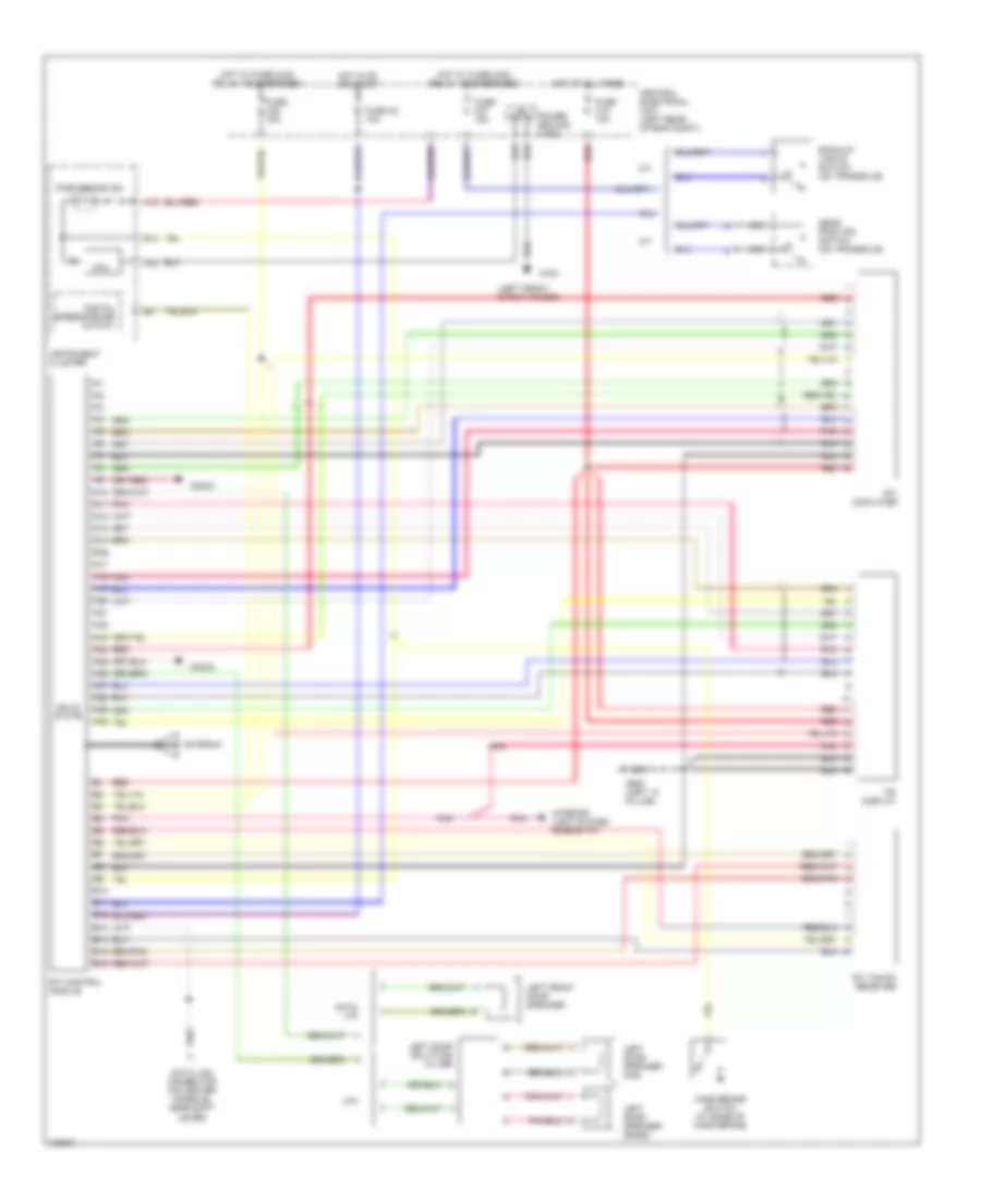
Электросхема навигации GPS для Volvo V70 XC 1998
 https://portal-diagnostov.com/license.html
Automotive Electricians Portal FZCO
Automotive Electricians Portal FZCO
https://portal-diagnostov.com/license.html
https://portal-diagnostov.com/license.html
Automotive Electricians Portal FZCO
Automotive Electricians Portal FZCO
Электросхема навигации GPS для Volvo V70 XC 1998 - Список элементов:
- (left front strut tower)
- A/t
- A10
- A11
- A12
- A13
- A14
- A15
- A16 a15
- A17
- A18
- A19
- A20
- A21
- A22
- A23
- A24
- A25
- A26
- A27
- A28
- A29
- A30
- Antenna
- B10
- B11
- B12
- B13
- B14
- B15
- B16
- Back-up lights switch (on transaxle)
- C70
- Central electrical unit (left rear of eng compt)
- Cpu
- Data link connector (on center console, near shift lever)
- Digital speedometer output
- Fuse c15 10a
- Fuse c2 10a
- Fuse c27 15a
- Fuse c30 15a
- G102
- G900 (left "a" pillar)
- Gear position switch (on transaxle)
- Hand brake switch (at base of hand brake)
- Hot at all times
- Hot in on or start
- Hot w/ overload relay 105 energized
- Hot w/ overload relay 106 energized
- Instrument cluster
- Interior light system (rheostat)
- Left door speaker (bass)
- Left door speaker (mid)
- Left door splitting filter
- Left front door speaker
- M/t
- Nca
- Park brake ind.
- Pnk
- Power ground conn.
- Radio
- Red
- Rti cd-player
- Rti control module
- Rti tmc/fm receiver
- S70 & v70
- Solid state
- Tri display
 Čeština
 Dansk
Dansk Deutsch
 Ελληνικά
 English
 English
 Español
 Suomi
Suomi Français
 Français
 עברית
עברית Hrvatski
 Magyar
 Italiano
 한국어
한국어 Nederlands
 Polski
 Português
 Português
 Română
 Русский
 Slovenčina
 Slovenščina
 Svenska
 Türkçe
 中文 (中国)
 日本語
日本語
