ENGINE PERFORMANCE
4.3L
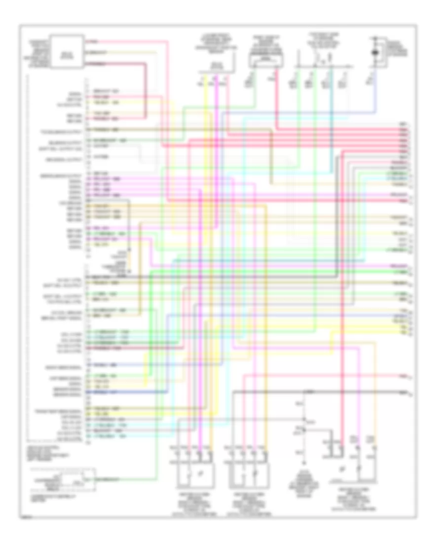
4.3L (VIN W), Engine Performance Wiring Diagrams (1 of 4) for Chevrolet Chevy Express G2500 1997
 https://portal-diagnostov.com/license.html
Automotive Electricians Portal FZCO
Automotive Electricians Portal FZCO
https://portal-diagnostov.com/license.html
https://portal-diagnostov.com/license.html
Automotive Electricians Portal FZCO
Automotive Electricians Portal FZCO
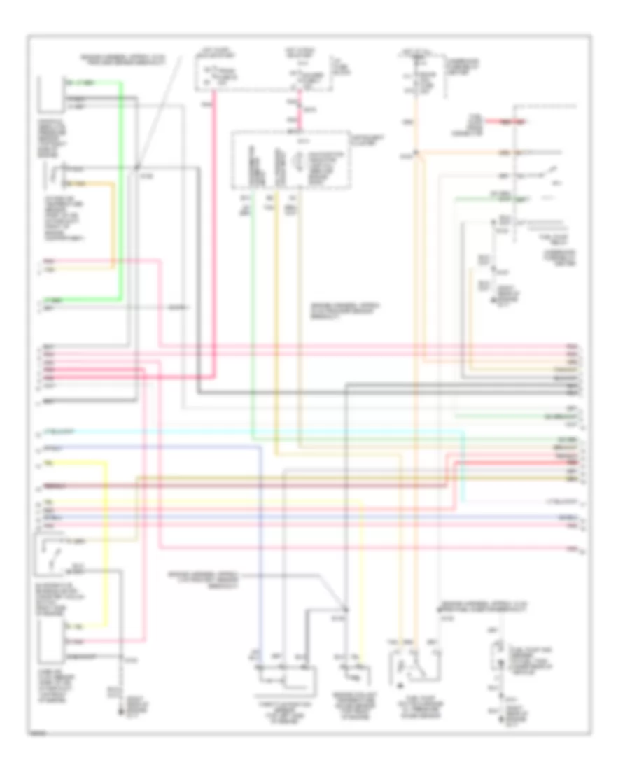
List of elements for 4.3L (VIN W), Engine Performance Wiring Diagrams (1 of 4) for Chevrolet Chevy Express G2500 1997:
- (lower front of engine, near crankshaft) crankshaft position sensor
- (near thermostat housing) g125
- (right side of engine) evaporative canister purge solenoid valve
- (top right side of engine)
- A/c coil ground
- A/c compressor enable relay
- Camshaft position sensor (part of distributor, top rear of engine)
- Coil
- Coil a high
- Coil a low
- Coil b high
- Coil b low
- Egr sol posit signal
- Egr solenoid output
- G119 (engine harness at generator bracket; right front of engine)
- Heated oxygen sensor bank 1 sensor 1 (in exhaust pipe, in front of catalytic converter)
- Heated oxygen sensor bank 1 sensor 2 (in exhaust pipe, in back of catalytic converter)
- Heated oxygen sensor bank 2 sensor 1 (in exhaust pipe, in front of catalytic converter)
- Idle air control valve motor
- Ignition
- Inj no.1 ctrl
- Inj no.2 ctrl
- Inj no.3 ctrl
- Inj no.4 ctrl
- Inj no.5 ctrl
- Inj no.6 ctrl
- Knock sens signal
- Knock sensor (top rear of engine)
- Maf signal
- Map sens signal
- Nca
- Pnk
- Pnk c
- Return
- S101
- S102
- S103
- S301
- Sensor signal
- Shift sol. a output
- Shift sol. b output
- Shift sol. output (3/2)
- Signal
- Solenoid output
- Solid state
- Tan
- Tcc pwm sol ctrl
- Tcc solenoid output
- Trans temp sens signal
- Underhood fuse-relay center
- Vcm ground
- Vehicle control module (vcm) (engine compartment, left fender)
- Vss signal output
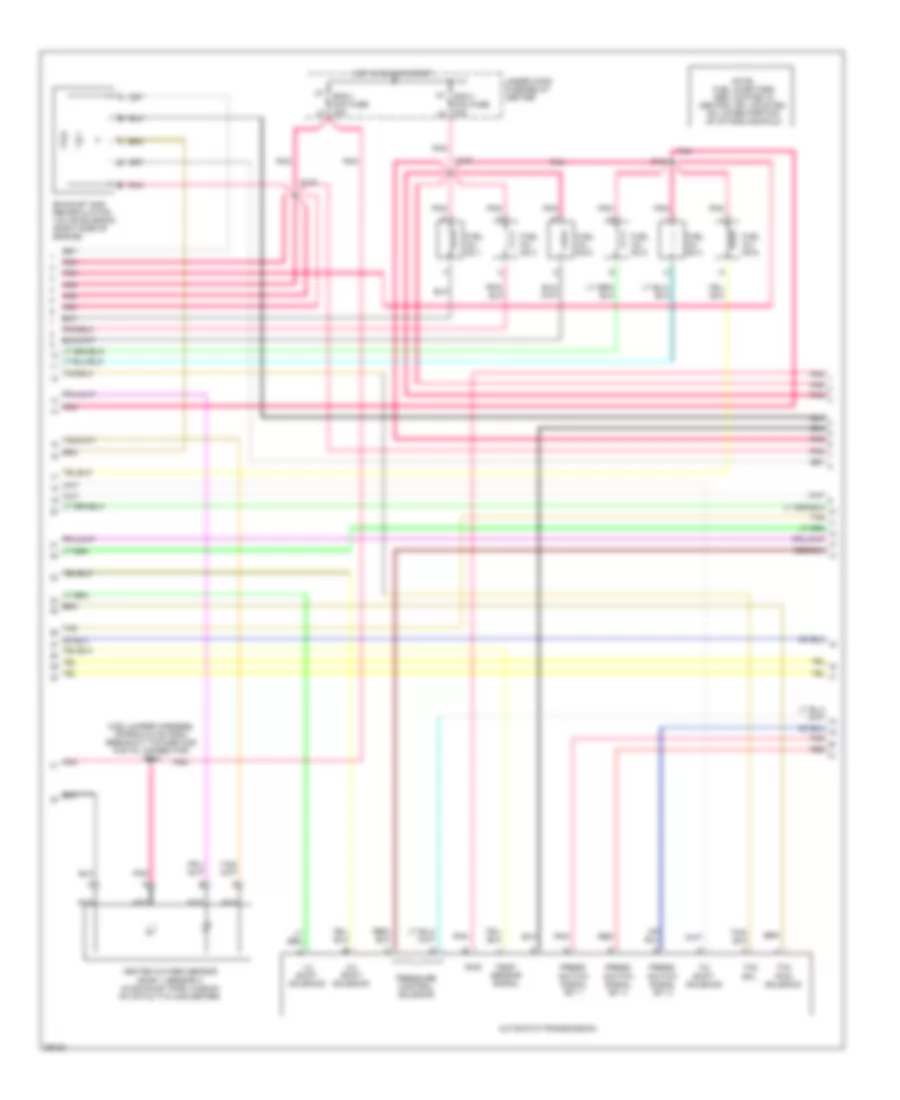
4.3L (VIN W), Engine Performance Wiring Diagrams (2 of 4) for Chevrolet Chevy Express G2500 1997
 https://portal-diagnostov.com/license.html
Automotive Electricians Portal FZCO
Automotive Electricians Portal FZCO
https://portal-diagnostov.com/license.html
https://portal-diagnostov.com/license.html
Automotive Electricians Portal FZCO
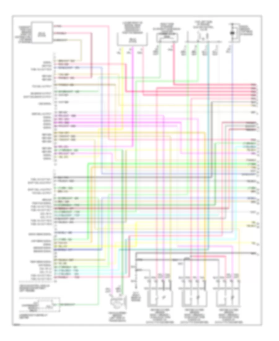
Automotive Electricians Portal FZCOList of elements for 4.3L (VIN W), Engine Performance Wiring Diagrams (2 of 4) for Chevrolet Chevy Express G2500 1997:
- (o2s jumper harness, approx 22 cm from breakout toward o2s pigtail connector) s304
- 1-2 shift solenoid
- 2-3 shift solenoid
- 3-2 shift solenoid
- Automatic transmission
- Eng-1 mini fuse 20a
- Exhaust gas recirculation valve solenoid (right side of engine)
- Fuel inj. no.1
- Fuel inj. no.2
- Fuel inj. no.3
- Fuel inj. no.4
- Fuel inj. no.5
- Fuel inj. no.6
- H7 ecm-1 mini fuse 20a
- Heated oxygen sensor bank 1 sensor 3 (in exhaust pipe, in back of catalytic converter)
- Hot in run or start
- Nca
- Note: fuel injectors are located in central sfi, mounted on lower portion of intake manifold
- Pnk
- Pnk pnk pnk
- Press. switch signal bit 1
- Press. switch signal bit 2
- Press. switch signal bit 3
- Pressure control solenoid
- Pwr
- Red
- S130
- S132
- S133
- Tan
- Tcc pwm solenoid
- Tcc sol.
- Temp. sensor signal
- Under hood fuse-relay center
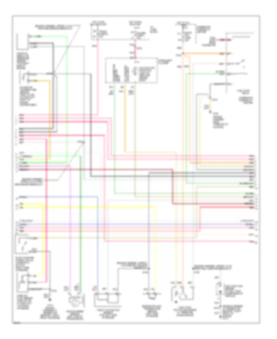
4.3L (VIN W), Engine Performance Wiring Diagrams (3 of 4) for Chevrolet Chevy Express G2500 1997
 https://portal-diagnostov.com/license.html
Automotive Electricians Portal FZCO
Automotive Electricians Portal FZCO
https://portal-diagnostov.com/license.html
https://portal-diagnostov.com/license.html
Automotive Electricians Portal FZCO
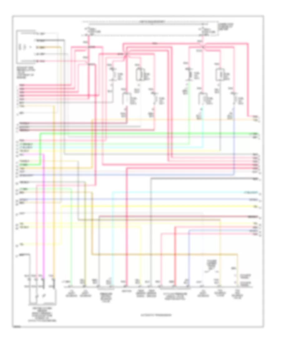
Automotive Electricians Portal FZCOList of elements for 4.3L (VIN W), Engine Performance Wiring Diagrams (3 of 4) for Chevrolet Chevy Express G2500 1997:
- (engine harness at generator bracket; right front of engine) g119
- (engine harness, approx 12 cm from fuel injector breakout)
- (engine harness, approx 15 cm from egr sensor breakout)
- (engine harness, approx 33 cm from egr sensor breakout)
- (engine harness, approx 4 cm from ect sensor breakout)
- (engine harness, near thermostat housing)
- B14
- B17
- Ecm-b mini fuse 20a
- Engine coolant temperature sensor (left side of engine)
- Evap canister purge vacuum diagnostic switch (right side of engine)
- F11
- Fuel pump and sender (in fuel tank under rear of vehicle)
- Fuel pump prime connector
- Fuel pump relay
- Fuel pump switch and engine oil pressure gauge sensor
- G119 (engine harness at generator bracket, right front of engine)
- G12
- G125
- Gauge input oil pressure
- Gauges fuse 4 10a
- Hot at all times
- Hot in off, run or start
- Hot in run or start
- I/p fuse block
- Input odometer speedometer/
- Instrument cluster
- Intake air temperature sensor (part of air intake duct, front of engine compartment)
- Malfunction indicator lamp (mil) "service engine soon"
- Manifold absolute pressure sensor (top right side of engine)
- Mass air flow sensor (part of air intake duct, top front of engine)
- Pnk
- Red
- S102
- S120
- S136
- S137
- S138
- S139
- S216
- Tan
- Tan a
- Throttle position sensor (top left side of engine)
- Trans fuse 20 10a
- Underhood fuse-relay center
- Vehicle speed sensor (left side of transmission)
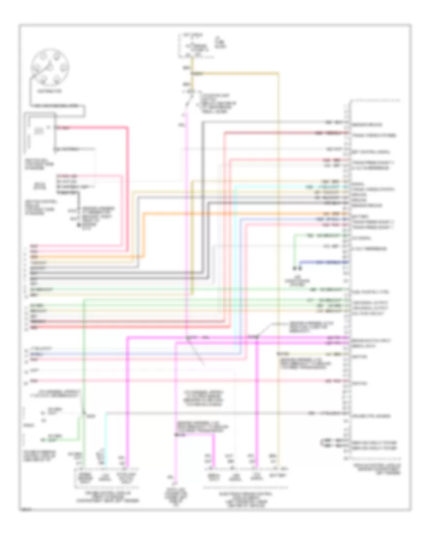
4.3L (VIN W), Engine Performance Wiring Diagrams (4 of 4) for Chevrolet Chevy Express G2500 1997
 https://portal-diagnostov.com/license.html
Automotive Electricians Portal FZCO
Automotive Electricians Portal FZCO
https://portal-diagnostov.com/license.html
https://portal-diagnostov.com/license.html
Automotive Electricians Portal FZCO
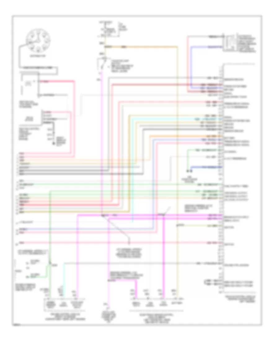
Automotive Electricians Portal FZCOList of elements for 4.3L (VIN W), Engine Performance Wiring Diagrams (4 of 4) for Chevrolet Chevy Express G2500 1997:
- (engine harness at generator bracket; right front of engine) g119
- (engine harness, 20 cm from fuel injector breakout)
- (engine harness, 4 cm from breakout to ground towards transmission) s153
- (engine harness, 8 cm from breakout to ground towards transmission)
- (i/p harness, approx 17 cm into vss breakout)
- (i/p harness, approx 27 cm from engine sensors inline conn. toward bulkhead)
- 5 volt reference
- 5 volts reference
- A/c signal
- Air conditioning system
- Battery
- Brake switch input
- Cruise control module (front of engine compartment near left fender)
- Cruise ctrl sig-eng
- Data link connector (under left side of i/p)
- Distributor
- Electronic brake control module (ebcm) (left frame rail near center of vehicle)
- Est control signal
- Fuel pump rly ctrl
- Ground
- High voltage coil wire
- Hot in run
- I/p fuse block
- Ignition
- Ignition coil (top right side of engine)
- Ignition control module (top right side of engine)
- M4 brake fuse 18 10a n3
- Mal func ind out
- Pnk
- Pnk a
- Power steering control module (center of i/p)
- Radio
- Red
- S103
- S113
- S122
- S154
- S210
- S239
- Sensor ground
- Serial data
- Service circuit power
- Signal
- Solid state
- Speed sensor input
- Stoplamp switch input
- Tcc signal
- Tcc/stoplamp switch (below center of i/p, near brake pedal lever)
- Trans press sig-bit 1
- Trans press sig-bit 2
- Trans press sig-bit 3
- Trans. force mtr feed
- Trans. force mtr rtn
- Vcm signal
- Vehicle control module (engine compartment, left fender)
- Vss signal
- Vss signal output
5.0L
5.0L (VIN M), Engine Performance Wiring Diagrams (1 of 4) for Chevrolet Chevy Express G2500 1997
 https://portal-diagnostov.com/license.html
Automotive Electricians Portal FZCO
Automotive Electricians Portal FZCO
https://portal-diagnostov.com/license.html
https://portal-diagnostov.com/license.html
Automotive Electricians Portal FZCO
Automotive Electricians Portal FZCOList of elements for 5.0L (VIN M), Engine Performance Wiring Diagrams (1 of 4) for Chevrolet Chevy Express G2500 1997:
- (lower front of engine, near crankshaft) crankshaft position sensor
- (right side of engine) evaporative emission canister purge valve
- (top left side of engine) idle air control valve
- A/c compressor enable relay
- Camshaft position sensor (part of distributor, top rear of engine)
- Coil
- Coil "a" hi
- Coil "a" lo
- Coil "b" hi
- Coil "b" lo
- Egr sol output
- Fuel inj out no.1
- Fuel inj out no.2
- Fuel inj out no.3
- Fuel inj out no.4
- Fuel inj out no.5
- Fuel inj out no.6
- Fuel inj out no.7
- Fuel inj out no.8
- G117 (right rear of engine)
- Ground
- Heated oxygen sensor bank 1 sensor 1 (in exhaust pipe in front of catalytic converter)
- Heated oxygen sensor bank 1 sensor 2 (in exhaust pipe in back of catalytic converter)
- Heated oxygen sensor bank 1 sensor 3 (in exhaust pipe in back of catalytic converter)
- Ignition
- Knock sens signal
- Knock sensor (top rear of engine)
- Maf signal
- Map sens signal
- Nca
- Pnk
- Pnk c
- Position signal
- Return
- S101
- S103
- S301
- S304
- Sensor signal
- Shift sol a output
- Shift sol b output
- Shift solenoid output
- Signal
- Solenoid output
- Solid state
- Tan
- Tcc sol output
- Temp sens signal
- Underhood fuse-relay center
- Vehicle control module (engine compartment, left fender)
- Vehicle speed sensor (left side of transmission)
- Vss signal
5.0L (VIN M), Engine Performance Wiring Diagrams (2 of 4) for Chevrolet Chevy Express G2500 1997
 https://portal-diagnostov.com/license.html
Automotive Electricians Portal FZCO
Automotive Electricians Portal FZCO
https://portal-diagnostov.com/license.html
https://portal-diagnostov.com/license.html
Automotive Electricians Portal FZCO
Automotive Electricians Portal FZCOList of elements for 5.0L (VIN M), Engine Performance Wiring Diagrams (2 of 4) for Chevrolet Chevy Express G2500 1997:
- (w/4l60-e trans.)
- (w/4l80-e trans.)
- 1-2 shift solenoid
- 2-3 shift solenoid
- 3-2 shift solenoid
- A/t fluid pressure manual valve position switch
- Automatic transmission
- Ecm-1 mini fuse 20a
- Exhaust gas recirculation valve (top front of engine)
- Fuel inj. no.1
- Fuel inj. no.2
- Fuel inj. no.3
- Fuel inj. no.4
- Fuel inj. no.5
- Fuel inj. no.6
- Fuel inj. no.7
- Fuel inj. no.8
- Heated oxygen sensor bank 2 sensor 1 (in exhaust pipe in front of catalytic converter)
- Hot in run or start
- Ignition
- K7 eng-1 mini fuse 20a l8
- Nca
- Pnk
- Pnk tan
- Pressure control solenoid valve
- Red
- S130
- S131
- S132
- S133
- Tan
- Tcc pcm solenoid valve
- Tcc solenoid vlave
- Temp sensor ground
- Temp sensor signal
- Under hood fuse-relay center
- W/4l60e 4-speed trans. only
5.0L (VIN M), Engine Performance Wiring Diagrams (3 of 4) for Chevrolet Chevy Express G2500 1997
 https://portal-diagnostov.com/license.html
Automotive Electricians Portal FZCO
Automotive Electricians Portal FZCO
https://portal-diagnostov.com/license.html
https://portal-diagnostov.com/license.html
Automotive Electricians Portal FZCO
Automotive Electricians Portal FZCOList of elements for 5.0L (VIN M), Engine Performance Wiring Diagrams (3 of 4) for Chevrolet Chevy Express G2500 1997:
- (engine harness, approx 12 cm from fuel injector breakout)
- (engine harness, approx 15 cm from egr sensor breakout)
- (engine harness, approx 33 cm from egr sensor breakout)
- (engine harness, approx 4 cm from ect sensor breakout)
- (right rear of engine) g117
- B14
- B17
- Ecm-b mini fuse 20a
- Engine coolant temperature gauge sensor (top front of engine)
- Evaporative emission (evap) canister vacuum switch (right side of engine)
- F11
- Fuel pump and sender (in fuel tank under rear of vehicle)
- Fuel pump prime connector
- Fuel pump relay
- Fuel pump switch & engine oil pressure gauge sensor
- G12
- Gauges fuse 4 10a
- Hot at all times
- Hot in off, run or start
- Hot in run or start
- I/p fuse block
- Instrument cluster
- Intake air temperature sensor (part of air intake duct, front of engine compartment)
- Malfunction indicator lamp (mil) "service engine soon"
- Manifold absolute pressure sensor (top right side of engine)
- Mass air flow sensor (part of air intake duct, top front of engine)
- Oil pressure gauge input
- Pnk
- Pnk tan
- Red
- S101
- S102
- S120
- S136
- S137
- S138
- S139
- S157
- S216
- Speedometer/ odometer input
- Tan
- Tan b
- Throttle position sensor (top left side of engine)
- Trans fuse 20 10a
- Underhood fuse-relay center
5.0L (VIN M), Engine Performance Wiring Diagrams (4 of 4) for Chevrolet Chevy Express G2500 1997
 https://portal-diagnostov.com/license.html
Automotive Electricians Portal FZCO
Automotive Electricians Portal FZCO
https://portal-diagnostov.com/license.html
https://portal-diagnostov.com/license.html
Automotive Electricians Portal FZCO
Automotive Electricians Portal FZCOList of elements for 5.0L (VIN M), Engine Performance Wiring Diagrams (4 of 4) for Chevrolet Chevy Express G2500 1997:
- (engine harness, 20 cm from fuel injector breakout)
- (engine harness, 4 cm grom breakout to ground towards transmission) s153
- (i/p harness, approx 17 cm into vss breakout)
- (i/p harness, approx 27 cm from engine sensors inline conn. toward bulkhead)
- (right rear of engine) g117
- 5 volt reference
- 5 volts reference
- A/c signal
- Air conditioning system
- Automatic transmission input shaft speed sensor (w/4l80-e) (left side of transmission)
- Battery
- Brake switch input
- Cruise control module (front of engine compartment near left fender)
- Cruise ctrl sig eng
- Data link connector (under left side of i/p)
- Distributor
- Elec spark timing
- Electronic brake control module (ebcm) (left frame rail near center of vehicle)
- Force motor feed
- Force motor return
- Fuel pump rly feed
- Ground
- High voltage coil wire
- Hot in run
- I/p fuse block
- Ignition
- Ignition coil (top right side of engine)
- Ignition control module (top right side of engine)
- M4 brake fuse 18 10a n3
- Mal func lp output
- Pnk
- Pnk a
- Power steering control module (center of i/p)
- Pressure sw signal
- Radio
- Red
- Return
- S101
- S113
- S122
- S154
- S210
- S239
- Sensor ground
- Serial data
- Service circuit power
- Signal
- Solid state
- Speed sensor input
- Stoplamp switch input
- Tcc signal
- Tcc/stoplamp switch (below center of i/p, near brake pedal lever)
- Vcm signal
- Vehicle control module (engine compartment, left fender)
- Vss signal
- Vss signal output
5.7L
5.7L (VIN R), Engine Performance Wiring Diagrams (1 of 4) for Chevrolet Chevy Express G2500 1997
 https://portal-diagnostov.com/license.html
Automotive Electricians Portal FZCO
Automotive Electricians Portal FZCO
https://portal-diagnostov.com/license.html
https://portal-diagnostov.com/license.html
Automotive Electricians Portal FZCO
Automotive Electricians Portal FZCOList of elements for 5.7L (VIN R), Engine Performance Wiring Diagrams (1 of 4) for Chevrolet Chevy Express G2500 1997:
- (lower front of engine, near crankshaft) crankshaft position sensor
- (right side of engine) evaporative emission canister purge valve
- (top left side of engine) idle air control valve
- A/c compressor enable relay
- Camshaft position sensor (part of distributor, top rear of engine)
- Coil
- Coil "a" hi
- Coil "a" lo
- Coil "b" hi
- Coil "b" lo
- Egr sol output
- Fuel inj out no.1
- Fuel inj out no.2
- Fuel inj out no.3
- Fuel inj out no.4
- Fuel inj out no.5
- Fuel inj out no.6
- Fuel inj out no.7
- Fuel inj out no.8
- G117 (right rear of engine)
- Ground
- Heated oxygen sensor bank 1 sensor 1 (in exhaust pipe in front of catalytic converter)
- Heated oxygen sensor bank 1 sensor 2 (in exhaust pipe in back of catalytic converter)
- Heated oxygen sensor bank 1 sensor 3 (in exhaust pipe in back of catalytic converter)
- Ignition
- Knock sens signal
- Knock sensor (top rear of engine)
- Maf signal
- Map sens signal
- Nca
- Pnk
- Pnk c
- Position signal
- Return
- S101
- S103
- S301
- S304
- Sensor signal
- Shift sol a output
- Shift sol b output
- Shift solenoid output
- Signal
- Solenoid output
- Solid state
- Tan
- Tcc sol output
- Temp sens signal
- Underhood fuse-relay center
- Vehicle control module (engine compartment, left fender)
- Vehicle speed sensor (left side of transmission)
- Vss signal
5.7L (VIN R), Engine Performance Wiring Diagrams (2 of 4) for Chevrolet Chevy Express G2500 1997
 https://portal-diagnostov.com/license.html
Automotive Electricians Portal FZCO
Automotive Electricians Portal FZCO
https://portal-diagnostov.com/license.html
https://portal-diagnostov.com/license.html
Automotive Electricians Portal FZCO
Automotive Electricians Portal FZCOList of elements for 5.7L (VIN R), Engine Performance Wiring Diagrams (2 of 4) for Chevrolet Chevy Express G2500 1997:
- (w/4l60-e trans.)
- (w/4l80-e trans.)
- 1-2 shift solenoid
- 2-3 shift solenoid
- 3-2 shift solenoid
- A/t fluid pressure manual valve position switch
- Automatic transmission
- Ecm-1 mini fuse 20a
- Exhaust gas recirculation valve (top front of engine)
- Fuel inj. no.1
- Fuel inj. no.2
- Fuel inj. no.3
- Fuel inj. no.4
- Fuel inj. no.5
- Fuel inj. no.6
- Fuel inj. no.7
- Fuel inj. no.8
- Heated oxygen sensor bank 2 sensor 1 (in exhaust pipe in front of catalytic converter)
- Hot in run or start
- Ignition
- K7 eng-1 mini fuse 20a l8
- Nca
- Pnk
- Pnk tan
- Pressure control solenoid valve
- Red
- S130
- S131
- S132
- S133
- Tan
- Tcc pcm solenoid valve
- Tcc solenoid vlave
- Temp sensor ground
- Temp sensor signal
- Under hood fuse-relay center
- W/4l60e 4-speed trans. only
5.7L (VIN R), Engine Performance Wiring Diagrams (3 of 4) for Chevrolet Chevy Express G2500 1997
 https://portal-diagnostov.com/license.html
Automotive Electricians Portal FZCO
Automotive Electricians Portal FZCO
https://portal-diagnostov.com/license.html
https://portal-diagnostov.com/license.html
Automotive Electricians Portal FZCO
Automotive Electricians Portal FZCOList of elements for 5.7L (VIN R), Engine Performance Wiring Diagrams (3 of 4) for Chevrolet Chevy Express G2500 1997:
- (engine harness, approx 12 cm from fuel injector breakout)
- (engine harness, approx 15 cm from egr sensor breakout)
- (engine harness, approx 33 cm from egr sensor breakout)
- (engine harness, approx 4 cm from ect sensor breakout)
- (right rear of engine) g117
- B14
- B17
- Ecm-b mini fuse 20a
- Engine coolant temperature gauge sensor (top front of engine)
- Evaporative emission (evap) canister vacuum switch (right side of engine)
- F11
- Fuel pump and sender (in fuel tank under rear of vehicle)
- Fuel pump prime connector
- Fuel pump relay
- Fuel pump switch & engine oil pressure gauge sensor
- G12
- Gauges fuse 4 10a
- Hot at all times
- Hot in off, run or start
- Hot in run or start
- I/p fuse block
- Instrument cluster
- Intake air temperature sensor (part of air intake duct, front of engine compartment)
- Malfunction indicator lamp (mil) "service engine soon"
- Manifold absolute pressure sensor (top right side of engine)
- Mass air flow sensor (part of air intake duct, top front of engine)
- Oil pressure gauge input
- Pnk
- Pnk tan
- Red
- S101
- S102
- S120
- S136
- S137
- S138
- S139
- S157
- S216
- Speedometer/ odometer input
- Tan
- Tan b
- Throttle position sensor (top left side of engine)
- Trans fuse 20 10a
- Underhood fuse-relay center
5.7L (VIN R), Engine Performance Wiring Diagrams (4 of 4) for Chevrolet Chevy Express G2500 1997
 https://portal-diagnostov.com/license.html
Automotive Electricians Portal FZCO
Automotive Electricians Portal FZCO
https://portal-diagnostov.com/license.html
https://portal-diagnostov.com/license.html
Automotive Electricians Portal FZCO
Automotive Electricians Portal FZCOList of elements for 5.7L (VIN R), Engine Performance Wiring Diagrams (4 of 4) for Chevrolet Chevy Express G2500 1997:
- (engine harness, 20 cm from fuel injector breakout)
- (engine harness, 4 cm grom breakout to ground towards transmission) s153
- (i/p harness, approx 17 cm into vss breakout)
- (i/p harness, approx 27 cm from engine sensors inline conn. toward bulkhead)
- (right rear of engine) g117
- 5 volt reference
- 5 volts reference
- A/c signal
- Air conditioning system
- Automatic transmission input shaft speed sensor (w/4l80-e) (left side of transmission)
- Battery
- Brake switch input
- Cruise control module (front of engine compartment near left fender)
- Cruise ctrl sig eng
- Data link connector (under left side of i/p)
- Distributor
- Elec spark timing
- Electronic brake control module (ebcm) (left frame rail near center of vehicle)
- Force motor feed
- Force motor return
- Fuel pump rly feed
- Ground
- High voltage coil wire
- Hot in run
- I/p fuse block
- Ignition
- Ignition coil (top right side of engine)
- Ignition control module (top right side of engine)
- M4 brake fuse 18 10a n3
- Mal func lp output
- Pnk
- Pnk a
- Power steering control module (center of i/p)
- Pressure sw signal
- Radio
- Red
- Return
- S101
- S113
- S122
- S154
- S210
- S239
- Sensor ground
- Serial data
- Service circuit power
- Signal
- Solid state
- Speed sensor input
- Stoplamp switch input
- Tcc signal
- Tcc/stoplamp switch (below center of i/p, near brake pedal lever)
- Vcm signal
- Vehicle control module (engine compartment, left fender)
- Vss signal
- Vss signal output

 Čeština
 Dansk
Dansk Deutsch
 Ελληνικά
 English
 English
 Español
 Suomi
Suomi Français
 Français
 עברית
עברית Hrvatski
 Magyar
 Italiano
 한국어
한국어 Nederlands
 Polski
 Português
 Português
 Română
 Русский
 Slovenčina
 Slovenščina
 Svenska
 Türkçe
 中文 (中国)
