ENGINE PERFORMANCE
5.7L
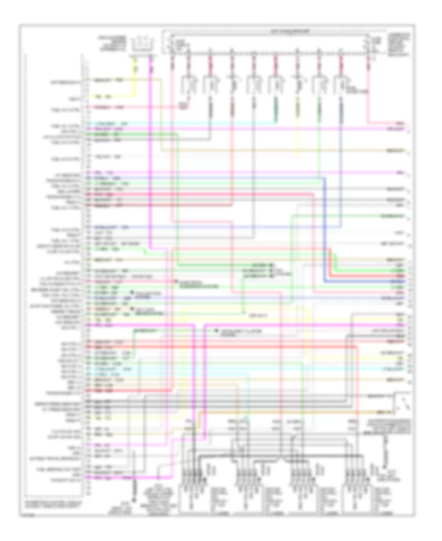
5.7L (VIN G), Engine Performance Wiring Diagrams (1 of 4) for Chevrolet Corvette 1998
 https://portal-diagnostov.com/license.html
Automotive Electricians Portal FZCO
Automotive Electricians Portal FZCO
https://portal-diagnostov.com/license.html
https://portal-diagnostov.com/license.html
Automotive Electricians Portal FZCO
Automotive Electricians Portal FZCO
List of elements for 5.7L (VIN G), Engine Performance Wiring Diagrams (1 of 4) for Chevrolet Corvette 1998:
- (c60 only)
- (right top side of eng)
- (top left plug side of eng)
- 1-2 ss valve ctrl
- 1-4 lmp or 2-3 ss ctrl
- 2nd/3th gear or 3-2 ss
- 375 or 1223
- 451c
- 451h
- 587 or 687
- A/c clutch status
- A/c request
- A/c system
- Anti-lock brake system
- Ckp sens sig in
- Clutch sw sig
- Cmp sens sig in
- Cool fan 1 rly ctrl
- Cooling fans system
- Desire torque
- Electronic suspension system
- Evap can purge val ctrl
- Evap vac sw sig
- Evaporative emission vaccuum purge switch (on top left side of eng, on intake manifold)
- Extend travel brake sw
- Fuel inj 1 ctrl
- Fuel inj 2 ctrl
- Fuel inj 3 ctrl
- Fuel inj 4 ctrl
- Fuel inj 5 ctrl
- Fuel inj 6 ctrl
- Fuel inj 7 ctrl
- Fuel inj 8 ctrl
- Fuel injectors
- Fuel sending unit gnd
- G112
- G120
- Gnd
- Gnd jumper
- Hot in run or start
- Iat sens gnd
- Ign
- Ign ctrl 1
- Ign ctrl 2
- Ign ctrl 3
- Ign ctrl 4
- Ign ctrl 5
- Ign ctrl 6
- Ign ctrl 7
- Ign ctrl 8
- Ign ctrl sig
- Ignition control/ coil module 1 (at top of cylinder)
- Ignition control/ coil module 3 (at top of cylinder)
- Ignition control/ coil module 5 (at top of cylinder)
- Ignition control/ coil module 7 (at top of cylinder)
- Injr1 fuse 22 15a
- Injr2 fuse 15a
- Instrument cluster system
- Maf sens sig
- Mil ctrl
- Nca
- Oil press sens gnd
- Pcm chassis pitch in
- Plug
- Pnk
- Powertrain control module (on right side of eng compt)
- Prnd 'a'
- Prnd 'c'
- Prnd 'p'
- Prnd p
- Red
- Ref lo
- Refrig press sens gnd
- Reverse inhibit sol ctrl
- S101 (left ign ctrl module jumper, approx 6 cm from conn breakout toward ign ctrl/coil module #1)
- S120
- Spark
- Tcc/shift sw in
- Trans range 'a' in
- Trans range 'b' in
- Trans range 'c' in
- Underhood electrical center (on right rear of eng compt)
- Vehicle speed sensor (on right of differential)
- Vss hi
- Vss lo
- Vss sig out
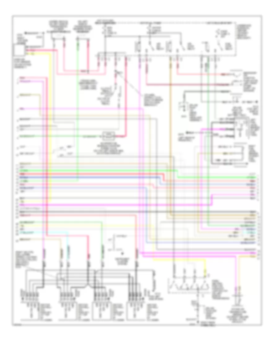
5.7L (VIN G), Engine Performance Wiring Diagrams (2 of 4) for Chevrolet Corvette 1998
 https://portal-diagnostov.com/license.html
Automotive Electricians Portal FZCO
Automotive Electricians Portal FZCO
https://portal-diagnostov.com/license.html
https://portal-diagnostov.com/license.html
Automotive Electricians Portal FZCO
Automotive Electricians Portal FZCOList of elements for 5.7L (VIN G), Engine Performance Wiring Diagrams (2 of 4) for Chevrolet Corvette 1998:
- (i/p harn, approx 7.5 cm right of brake switch conn breakout)
- (left rear of frame rail)
- (on left side of transmission) reverse inhibit solenoid
- (right ign ctrl mod jumper, approx 4 cm from ignition ctrl/coil mod conn 4 breakout) s104
- (right rear wheelwell)
- (right top side of eng)
- (top left plug side of eng)
- (trans harn, near breakout to fuel tank jumper harn)
- (under vehicle, on left side of transmission) 2-3 gear blockout solenoid
- 10a
- A/t
- A12
- Air pmp fuse 50 20a
- Air pump relay
- Air sol relay
- B pnk
- Clutch pedal switch (m/t) (on top of clutch pedal)
- D10
- E12
- Eng ign1 fuse 19
- Evaporative emission canister purge valve (on top left side of eng, on intake manifold)
- F/pmp fuse 13 20a
- F12
- Fuel pump relay
- G101
- G103
- G112
- G112 (top left side of eng)
- G120
- G416
- Gnd
- Hot at all times
- Hot in run or start
- Hot with ign1 relay energized
- Ign
- Ign ctrl sig
- Ignition control/ coil module 2 (at top of cylinder)
- Ignition control/ coil module 4 (at top of cylinder)
- Ignition control/ coil module 6 (at top of cylinder)
- Ignition control/ coil module 8 (at top of cylinder)
- Instrument cluster system
- Intake air temperature sensor (on front center of eng, in the air duct)
- Left fuel level sensor (in left fuel tank)
- M/t
- Mass air flow sensor (on air intake assembly)
- Nca
- Park/ neutral position & backup lamp switch (on left side of transmission)
- Plug spark
- Pnk
- Red
- Red a
- Ref lo
- Right fuel level sensor (in right fuel tank)
- S120
- S213
- S400
- S444
- S466
- Secondary air injection pump motor (left front of eng compt, on skid bar)
- Spark
- Spark plug
- Splice pack (near right headlamp assembly)
- Splice pack 122 (below battery tray)
- Splice pack 208 (right side of dash)
- Tan
- Underhood elecrical center (on right rear of eng compt)
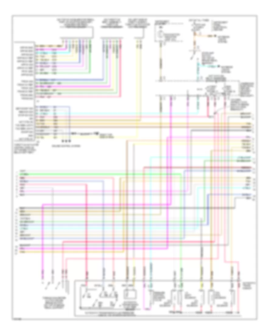
5.7L (VIN G), Engine Performance Wiring Diagrams (3 of 4) for Chevrolet Corvette 1998
 https://portal-diagnostov.com/license.html
Automotive Electricians Portal FZCO
Automotive Electricians Portal FZCO
https://portal-diagnostov.com/license.html
https://portal-diagnostov.com/license.html
Automotive Electricians Portal FZCO
Automotive Electricians Portal FZCOList of elements for 5.7L (VIN G), Engine Performance Wiring Diagrams (3 of 4) for Chevrolet Corvette 1998:
- (i/p harn, approx 7.5 cm right of brake switch conn breakout)
- (mil)
- (on left side of throttle body) throttle actuator control motor
- (on throttle body assembly) throttle position sensor
- (on top of accelerator pedal, part of mounting bracket) accelerator pedal position sensor
- (right top side of eng)
- 1-2 shift solenoid
- 2-3 shift solenoid
- 3-2 shift solenoid
- Act ctrl #1
- Act ctrl #2
- App #1 5v ref
- App #1 sig
- App #2 5v ref
- App #2 gnd
- App #2 sig
- App #3 5v ref
- App #3 gnd
- App #3 sig
- Automatic trans- mission
- Automatic transmission fluid pressure
- Automatic transmission fluid temp sensor
- B16
- Cruise control system
- D2 sw
- D3 sw
- D4 sw
- Eng ign 1 fuse 19 15a
- Exterior lights system
- Fuse 8 20a b
- G120
- Gnd
- Hot at all times
- Hot with ign relay energized (in run or start)
- Ign
- Instrument cluster
- Instrument panel electrical center
- Lo sw
- Malfunction indicator lamp
- Manual valve position switch
- On/off sig
- Pessure control solenoid valve
- Pnk
- Pp #1 gnd
- Red
- Res/acc sig
- Rev sw
- S120
- S213
- Set/coast sig
- Stop sw sig
- Stoplamp switch (on top of brake pedal support) c2
- Stp haz a
- Tac serl data
- Tan
- Tcc pwm solenoid
- Tcc solenoid
- Throt cont fuse 17 15a
- Throttle actuator control module (attached to pcm, below battery)
- Torque converter clutch cruise brake switch) (on top of brake pedal support)
- Tps #1 5v ref
- Tps #1 sig
- Tps #2 5v ref
- Tps #2 gnd
- Tps #2 sig
- Underhood electrical center (on right rear of eng compt)
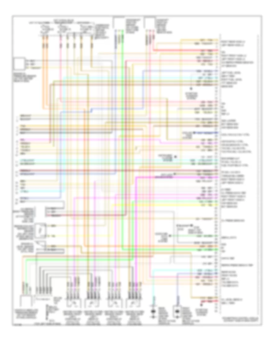
5.7L (VIN G), Engine Performance Wiring Diagrams (4 of 4) for Chevrolet Corvette 1998
 https://portal-diagnostov.com/license.html
Automotive Electricians Portal FZCO
Automotive Electricians Portal FZCO
https://portal-diagnostov.com/license.html
https://portal-diagnostov.com/license.html
Automotive Electricians Portal FZCO
Automotive Electricians Portal FZCOList of elements for 5.7L (VIN G), Engine Performance Wiring Diagrams (4 of 4) for Chevrolet Corvette 1998:
- (below battery tray)
- (right top side of eng)
- (top left side of eng)
- 340b
- 340c
- 451e
- 451f
- 5v feed
- A/c refrig press sens sig
- A/c refrig- erant pressure sensor (attatched to a/c high side line)
- Air pump rly ctrl
- Air solenoid rly ctrl
- Anti-lock brake system
- Camshaft position sensor (on top center rear of eng)
- Computer data lines system
- Cool fan 2 & 3 rly ctrl
- Cooling fans system
- Crankshaft position sensor (on lower right side of eng)
- Ect sens gnd
- Ect sens sig
- Eng speed out
- Engine coolant temperature sensor (on left side of eng, below generator)
- Engine oil level sensor (on left side of oil pan)
- Engine oil pressure sensor (on top center rear of eng)
- F11
- Front knock sensor (center of eng, below intake manifold)
- Front ks sig
- Fuel pump relay ctrl
- Fuse 16 15a b
- Fuse 23 10a b
- G106
- G112
- Gen f term
- Gen l term
- Gnd
- Gnd jumper
- Heated oxygen sensor, front (left) (forward of catalytic converter)
- Heated oxygen sensor, front (right) (forward of catalytic converter)
- Heated oxygen sensor, rear (left) (rear of catalytic converter)
- Heated oxygen sensor, rear (right) (rear of catalytic converter)
- Hot at all times
- Hot in run
- Hot in run, bulb test or start
- Iat sens sig
- Ign
- Instrument cluster system
- Left front ho2s hi
- Left front ho2s lo
- Left fuel level
- Left rear ho2s hi
- Left rear ho2s lo
- Manifold absolute pressure sensor (on top rear of intake manifold)
- Map 5v ref
- Map sens gnd
- Map sens sig
- Nca
- Oil level sens in
- Oil press sens sig
- Oil press sig 5v ref
- Oxy sen fuse 15 15a
- Pc sol valve hi
- Pc sol valve lo
- Pcm 1 a
- Pcm a
- Pnk
- Powertrain control module (on right side of eng compt)
- Rear knock sensor (center of eng, below intake manifold)
- Rear ks sig
- Red
- Ref lo
- Refrig press sens 5v ref
- Right front ho2s hi
- Right front ho2s lo
- Right fuel level
- Right rear ho2s hi
- Right rear ho2s lo
- S120
- Sens gnd
- Serial data
- Splice pack
- Starting/ charging
- Starting/ charging system
- System
- Tac ser data
- Tan
- Tcc pwm sol valve ctrl
- Tcc sol valve ctrl
- Tft sens sig
- Torque delivered
- Underhood electrical center (on right rear of eng compt) c1

 Čeština
 Dansk
Dansk Deutsch
 Ελληνικά
 English
 English
 Español
 Suomi
Suomi Français
 Français
 עברית
עברית Hrvatski
 Magyar
 Italiano
 한국어
한국어 Nederlands
 Polski
 Português
 Português
 Română
 Русский
 Slovenčina
 Slovenščina
 Svenska
 Türkçe
 中文 (中国)
