ENGINE PERFORMANCE
2.3L
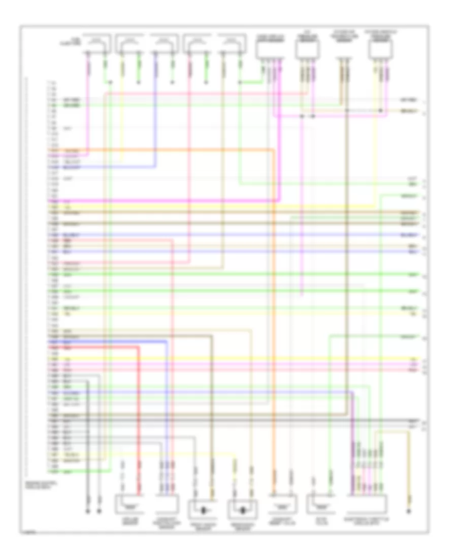
2.3L Turbo, Engine Performance Wiring Diagrams (1 of 3) for Volvo S60 T-5 2001
 https://portal-diagnostov.com/license.html
Automotive Electricians Portal FZCO
Automotive Electricians Portal FZCO
https://portal-diagnostov.com/license.html
https://portal-diagnostov.com/license.html
Automotive Electricians Portal FZCO
Automotive Electricians Portal FZCO
List of elements for 2.3L Turbo, Engine Performance Wiring Diagrams (1 of 3) for Volvo S60 T-5 2001:
- A/c pressure sensor
- A10
- A11
- A12
- A13
- A14
- A15
- A16
- A17
- A18
- A19
- A20
- A21
- A22
- A23
- A24
- A25
- A26
- A27
- A28
- A29
- A30
- A31
- A32
- A33
- A34
- A35
- A36
- A37
- A38
- A39
- A40
- A41
- A42
- A43
- A44
- A45
- A46
- A47
- A48
- A49
- A50
- A51
- A52
- A53
- A54
- A55
- A56
- A57
- A58
- A59
- A60
- A61
- A62
- A63
- A64
- A65
- A66
- A67
- A68
- A69
- A70
- Camshaft position (cmp) sensor
- Camshaft reset valve
- Electronic throttle module (etm)
- Engine control module (ecm)
- Evap valve
- Front knock sensor
- Fuel injectors
- Impulse sensor
- Intake air temperature sensor
- Intake manifold pressure sensor
- Mass airflow (maf) sensor
- Pnk
- Rear knock sensor
- Red
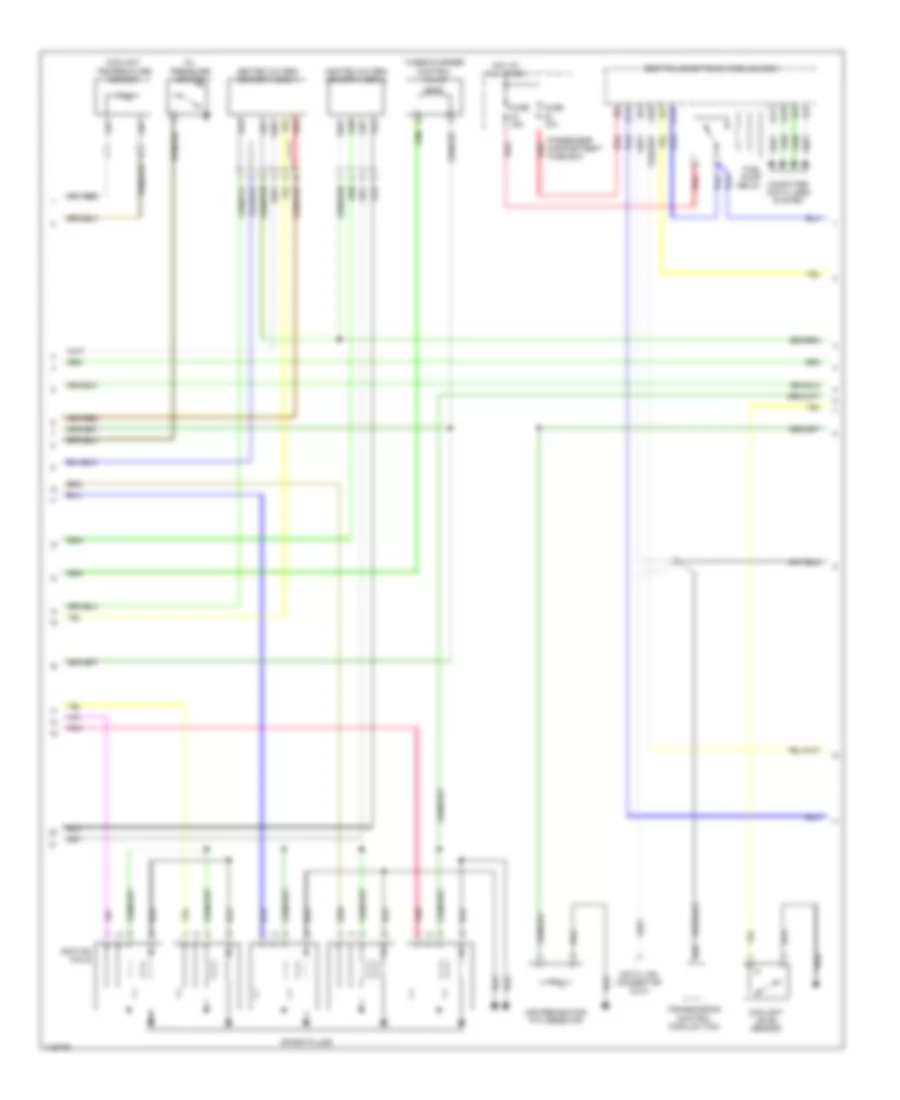
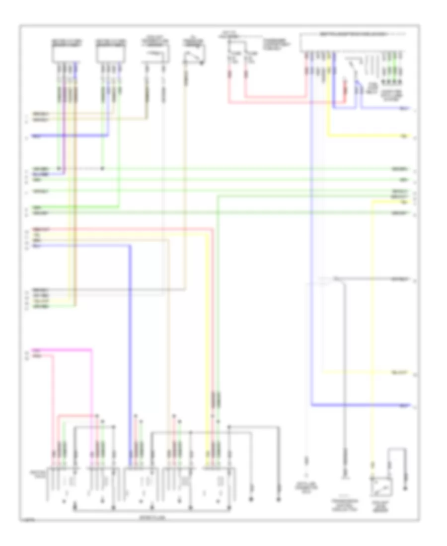
2.3L Turbo, Engine Performance Wiring Diagrams (2 of 3) for Volvo S60 T-5 2001
 https://portal-diagnostov.com/license.html
Automotive Electricians Portal FZCO
Automotive Electricians Portal FZCO
https://portal-diagnostov.com/license.html
https://portal-diagnostov.com/license.html
Automotive Electricians Portal FZCO
Automotive Electricians Portal FZCOList of elements for 2.3L Turbo, Engine Performance Wiring Diagrams (2 of 3) for Volvo S60 T-5 2001:
- A20
- Air preheating ptc resistor
- B14
- B17
- B18
- B22
- C14
- Central electronic module (cem)
- Computer data lines system
- Coolant level sensor
- Coolant temperature sensor
- Data link connector (dlc)
- Fuel pump relay
- Fuse 10a
- Fuse 15a
- Heated oxygen sensor (ho2s) 1
- Heated oxygen sensor (ho2s) 2
- Hot at all times
- Ignition coils
- Oil pressure sensor
- Passenger compartment fuse box
- Pnk
- Red
- Spark plugs
- Transmission control module (tcm)
- Turbocharger control valve
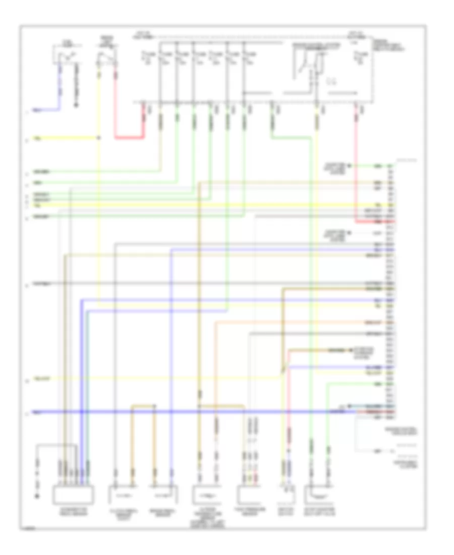
2.3L Turbo, Engine Performance Wiring Diagrams (3 of 3) for Volvo S60 T-5 2001
 https://portal-diagnostov.com/license.html
Automotive Electricians Portal FZCO
Automotive Electricians Portal FZCO
https://portal-diagnostov.com/license.html
https://portal-diagnostov.com/license.html
Automotive Electricians Portal FZCO
Automotive Electricians Portal FZCOList of elements for 2.3L Turbo, Engine Performance Wiring Diagrams (3 of 3) for Volvo S60 T-5 2001:
- 15/20
- 15/23
- 15/24
- 15/25
- A/c system
- Accelerator pedal sensor
- B10
- B11
- B12
- B13
- B14
- B15
- B16
- B17
- B18
- B19
- B20
- B21
- B22
- B23
- B24
- B25
- B26
- B27
- B28
- B29
- B30
- B31
- B32
- B33
- B34
- B35
- B36
- B37
- B38
- B39
- B40
- B41
- B42
- B43
- B44
- B45
- B46
- Brake light switch
- Brake pedal sensor
- Clutch pedal sensor (w/m/t)
- Computer data lines system
- Engine compartment relay/fuse box
- Engine control module (ecm)
- Engine control system main relay
- Evap canister shut-off valve
- Fuel pump
- Fuse 10a
- Fuse 15a
- Fuse 20a
- Fuse 5a
- Hot at all times
- Ignition switch
- Instrument cluster
- Nca
- Outside temperature sensor (integral to left sideview mirror)
- Red
- Starting/ charging system
- Tank pressure sensor
2.4L
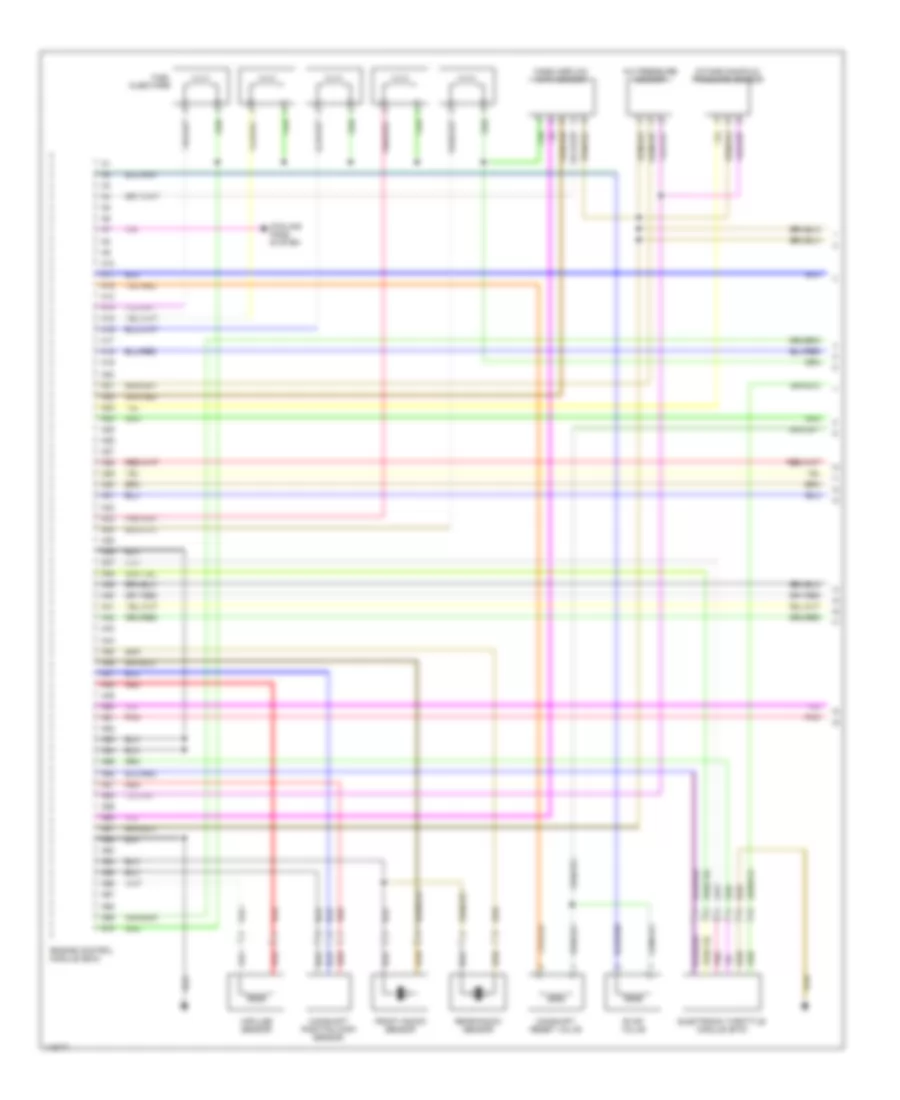
2.4L Turbo, Engine Performance Wiring Diagrams (1 of 3) for Volvo S60 T-5 2001
 https://portal-diagnostov.com/license.html
Automotive Electricians Portal FZCO
Automotive Electricians Portal FZCO
https://portal-diagnostov.com/license.html
https://portal-diagnostov.com/license.html
Automotive Electricians Portal FZCO
Automotive Electricians Portal FZCOList of elements for 2.4L Turbo, Engine Performance Wiring Diagrams (1 of 3) for Volvo S60 T-5 2001:
- A/c pressure sensor
- A10
- A11
- A12
- A13
- A14
- A15
- A16
- A17
- A18
- A19
- A20
- A21
- A22
- A23
- A24
- A25
- A26
- A27
- A28
- A29
- A30
- A31
- A32
- A33
- A34
- A35
- A36
- A37
- A38
- A39
- A40
- A41
- A42
- A43
- A44
- A45
- A46
- A47
- A48
- A49
- A50
- A51
- A52
- A53
- A54
- A55
- A56
- A57
- A58
- A59
- A60
- A61
- A62
- A63
- A64
- A65
- A66
- A67
- A68
- A69
- A70
- Camshaft position (cmp) sensor
- Camshaft reset valve
- Electronic throttle module (etm)
- Engine control module (ecm)
- Evap valve
- Front knock sensor
- Fuel injectors
- Impulse sensor
- Intake air temperature sensor
- Intake manifold pressure sensor
- Mass airflow (maf) sensor
- Pnk
- Rear knock sensor
- Red
2.4L Turbo, Engine Performance Wiring Diagrams (2 of 3) for Volvo S60 T-5 2001
 https://portal-diagnostov.com/license.html
Automotive Electricians Portal FZCO
Automotive Electricians Portal FZCO
https://portal-diagnostov.com/license.html
https://portal-diagnostov.com/license.html
Automotive Electricians Portal FZCO
Automotive Electricians Portal FZCOList of elements for 2.4L Turbo, Engine Performance Wiring Diagrams (2 of 3) for Volvo S60 T-5 2001:
- A20
- Air preheating ptc resistor
- B14
- B17
- B18
- B22
- C14
- Central electronic module (cem)
- Computer data lines system
- Coolant level sensor
- Coolant temperature sensor
- Data link connector (dlc)
- Fuel pump relay
- Fuse 10a
- Fuse 15a
- Heated oxygen sensor (ho2s) 1
- Heated oxygen sensor (ho2s) 2
- Hot at all times
- Ignition coils
- Oil pressure sensor
- Passenger compartment fuse box
- Pnk
- Red
- Spark plugs
- Transmission control module (tcm)
- Turbocharger control valve
2.4L Turbo, Engine Performance Wiring Diagrams (3 of 3) for Volvo S60 T-5 2001
 https://portal-diagnostov.com/license.html
Automotive Electricians Portal FZCO
Automotive Electricians Portal FZCO
https://portal-diagnostov.com/license.html
https://portal-diagnostov.com/license.html
Automotive Electricians Portal FZCO
Automotive Electricians Portal FZCOList of elements for 2.4L Turbo, Engine Performance Wiring Diagrams (3 of 3) for Volvo S60 T-5 2001:
- 15/20
- 15/23
- 15/24
- 15/25
- A/c system
- Accelerator pedal sensor
- B10
- B11
- B12
- B13
- B14
- B15
- B16
- B17
- B18
- B19
- B20
- B21
- B22
- B23
- B24
- B25
- B26
- B27
- B28
- B29
- B30
- B31
- B32
- B33
- B34
- B35
- B36
- B37
- B38
- B39
- B40
- B41
- B42
- B43
- B44
- B45
- B46
- Brake light switch
- Brake pedal sensor
- Clutch pedal sensor (w/m/t)
- Computer data lines system
- Engine compartment relay/fuse box
- Engine control module (ecm)
- Engine control system main relay
- Evap canister shut-off valve
- Fuel pump
- Fuse 10a
- Fuse 15a
- Fuse 20a
- Fuse 5a
- Hot at all times
- Ignition switch
- Instrument cluster
- Nca
- Outside temperature sensor (integral to left sideview mirror)
- Red
- Starting/ charging system
- Tank pressure sensor
2.4L, Engine Performance Wiring Diagrams (1 of 3) for Volvo S60 T-5 2001
 https://portal-diagnostov.com/license.html
Automotive Electricians Portal FZCO
Automotive Electricians Portal FZCO
https://portal-diagnostov.com/license.html
https://portal-diagnostov.com/license.html
Automotive Electricians Portal FZCO
Automotive Electricians Portal FZCOList of elements for 2.4L, Engine Performance Wiring Diagrams (1 of 3) for Volvo S60 T-5 2001:
- A/c pressure sensor
- A10
- A11
- A12
- A13
- A14
- A15
- A16
- A17
- A18
- A19
- A20
- A21
- A22
- A23
- A24
- A25
- A26
- A27
- A28
- A29
- A30
- A31
- A32
- A33
- A34
- A35
- A36
- A37
- A38
- A39
- A40
- A41
- A42
- A43
- A44
- A45
- A46
- A47
- A48
- A49
- A50
- A51
- A52
- A53
- A54
- A55
- A56
- A57
- A58
- A59
- A60
- A61
- A62
- A63
- A64
- A65
- A66
- A67
- A68
- A69
- A70
- Camshaft position (cmp) sensor
- Camshaft reset valve
- Cooling fans system
- Electronic throttle module (etm)
- Engine control module (ecm)
- Evap valve
- Front knock sensor
- Fuel injectors
- Impulse sensor
- Intake manifold pressure sensor
- Mass airflow (maf) sensor
- Pnk
- Rear knock sensor
- Red
2.4L, Engine Performance Wiring Diagrams (2 of 3) for Volvo S60 T-5 2001
 https://portal-diagnostov.com/license.html
Automotive Electricians Portal FZCO
Automotive Electricians Portal FZCO
https://portal-diagnostov.com/license.html
https://portal-diagnostov.com/license.html
Automotive Electricians Portal FZCO
Automotive Electricians Portal FZCOList of elements for 2.4L, Engine Performance Wiring Diagrams (2 of 3) for Volvo S60 T-5 2001:
- A20
- B14
- B17
- B18
- B22
- C14
- Central electronic module (cem)
- Computer data lines system
- Coolant level sensor
- Coolant temperature sensor
- Data link connector (dlc)
- Fuel pump relay
- Fuse 10a
- Fuse 15a
- Heated oxygen sensor (ho2s) 1
- Heated oxygen sensor (ho2s) 2
- Hot at all times
- Ignition coils
- Oil pressure sensor
- Passenger compartment fuse box
- Pnk
- Red
- Spark plugs
- Transmission control module (tcm)
2.4L, Engine Performance Wiring Diagrams (3 of 3) for Volvo S60 T-5 2001
 https://portal-diagnostov.com/license.html
Automotive Electricians Portal FZCO
Automotive Electricians Portal FZCO
https://portal-diagnostov.com/license.html
https://portal-diagnostov.com/license.html
Automotive Electricians Portal FZCO
Automotive Electricians Portal FZCOList of elements for 2.4L, Engine Performance Wiring Diagrams (3 of 3) for Volvo S60 T-5 2001:
- 15/20
- 15/23
- 15/24
- 15/25
- A/c system
- Accelerator pedal sensor
- B10
- B11
- B12
- B13
- B14
- B15
- B16
- B17
- B18
- B19
- B20
- B21
- B22
- B23
- B24
- B25
- B26
- B27
- B28
- B29
- B30
- B31
- B32
- B33
- B34
- B35
- B36
- B37
- B38
- B39
- B40
- B41
- B42
- B43
- B44
- B45
- B46
- Brake light switch
- Brake pedal sensor
- Clutch pedal sensor (w/m/t)
- Computer data lines system
- Engine compartment relay/fuse box
- Engine control module (ecm)
- Engine control system main relay
- Evap canister shut-off valve
- Fuel pump
- Fuse 10a
- Fuse 15a
- Fuse 20a
- Fuse 5a
- Hot at all times
- Ignition switch
- Instrument cluster
- Nca
- Outside temperature sensor (integral to left sideview mirror)
- Red
- Starting/ charging system
- Tank pressure sensor

 Čeština
 Dansk
Dansk Deutsch
 Ελληνικά
 English
 English
 Español
 Suomi
Suomi Français
 Français
 עברית
עברית Hrvatski
 Magyar
 Italiano
 한국어
한국어 Nederlands
 Polski
 Português
 Português
 Română
 Русский
 Slovenčina
 Slovenščina
 Svenska
 Türkçe
 中文 (中国)
