POWER DISTRIBUTION
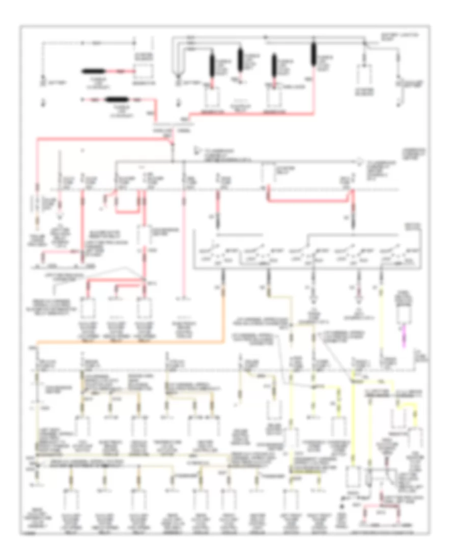
Power Distribution Wiring Diagram (1 of 4) for Chevrolet Chevy Express G3500 1998
 https://portal-diagnostov.com/license.html
Automotive Electricians Portal FZCO
Automotive Electricians Portal FZCO
https://portal-diagnostov.com/license.html
https://portal-diagnostov.com/license.html
Automotive Electricians Portal FZCO
Automotive Electricians Portal FZCO
List of elements for Power Distribution Wiring Diagram (1 of 4) for Chevrolet Chevy Express G3500 1998:
- (crossbody harness, approx 4 cm from convenience center conn breakout)
- (i/p harness, approx 18cm from bulkhead connector)
- (i/p harness, approx 24cm from bulkhead connector) s213
- (i/p harness, approx 4 cm from bulkhead connector)
- (rear a/c harness, approx 13 cm from blower motor resistor/ relay breakout)
- (rear a/c harness, approx 7cm from blower motor resistor breakout)
- (rear aux htr and a/c harness, approx 29cm from rear aux hvac module breakout)
- (upfitter provision harn, left side red
- (upfitter provisions harness, left side of dash)
- A13
- Abs fuse 60a
- Acc
- Ambulance
- Aux-a fuse 30a
- Aux-b fuse 30a
- Auxiliary battery
- Auxiliary blower motor high speed relay
- Auxiliary blower motor low speed relay
- Auxiliary blower motor medium speed relay
- Battery
- Battery junction block
- Blower fuse 60a
- Blower motor resistor relay
- Brake fuse 18 10a
- C202
- C206
- C210
- C302
- Convenience center
- Crank fuse 8 10a
- Cruise control module (gasoline)
- Cruise control switch
- Cruise fuse 6 10a
- Diesel
- Electronic brake control module
- Engine harn, near bulkhead connector)
- From aux-a fuse (diagram 1 of 4)
- Front auxiliary hvac control module
- Fusible link (10 ga- rust)
- Fusible link (10 ga-rust)
- G200 (left kick panel)
- Gasoline
- Generator
- Glowplug relay
- Heater and a/c control logic module
- Heater and a/c controller
- Htr a/c fuse 12 20a
- I/p fuse block
- Ign-a fuse 40a
- Ign-b fuse 50a
- Ignition switch
- Inline fuse 30a
- Left front power side window switch
- Lock
- Nca
- Of dash)
- Off
- P/b booster fluid flow alarm
- Park/ neutral position switch
- Passenger
- Pnk
- Pwr wdo fuse 25a
- Radio
- Radio 1 fuse 17 10a
- Rear auxiliary hvac control module
- Rear auxiliary mode valve and seal assembly
- Rear auxiliary temperature valve assembly
- Red
- Resistor
- Right front power side window switch
- Rr blower fuse 30a
- Rr hvac fuse 24 10a
- Run
- S122
- S134
- S201
- S210
- S220
- S229
- S307
- S311
- S312
- S404
- S405
- S412
- Start
- Starter relay
- Starter solenoid
- Tcc/ stoplamp switch
- Tcc/stoplamp switch breakout)
- Temperature valve actuator motor
- To s214 (diagram 3 of 4)
- To trans fuse (diagram 4 of 4)
- To underhood fuse-relay center (diagram 2 of 4)
- To upfitter provision relay (diagram 1 of 4)
- Trailer wiring provision
- Underhood fuse-relay center
- Upfitter provision connector
- Upfitter provision relay (behind left b pillar)
- Vehicle control module (gasoline)
- W/ rear a/c
- W/ uj1 brake warning
- W/ upfitter provisions
- Windshield washer/ wiper switch
- Windshield wiper motor
- Wiper fuse 11 25a
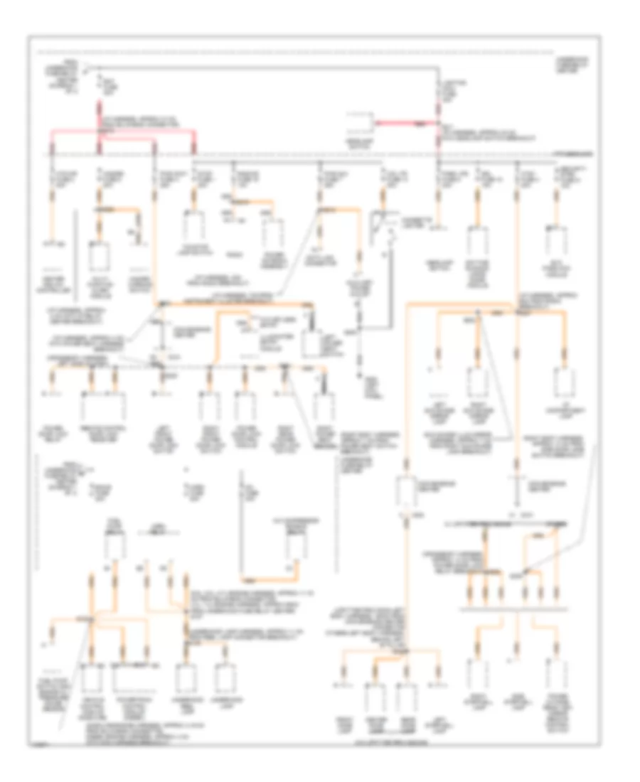
Power Distribution Wiring Diagram (2 of 4) for Chevrolet Chevy Express G3500 1998
 https://portal-diagnostov.com/license.html
Automotive Electricians Portal FZCO
Automotive Electricians Portal FZCO
https://portal-diagnostov.com/license.html
https://portal-diagnostov.com/license.html
Automotive Electricians Portal FZCO
Automotive Electricians Portal FZCOList of elements for Power Distribution Wiring Diagram (2 of 4) for Chevrolet Chevy Express G3500 1998:
- (6.5l, 5.0l, 5.7l-engine harness, approx 11-19 cm from bulkhead connector, 4.3l, 7.4l-engine harness, approx 65cm from underhood fuse relay center) s127
- (crossbody harness, approx 14 cm from power door lock relay breakout) s232
- (crossbody harness, left side of dash)
- (gasoline-engine harness, approx 4-19 cm from bulkhead connector, diesel-engine harness, approx 4 cm into main harness breakout)
- (i/p harness, 4cm from radio breakout)
- (i/p harness, 7cm from instrument cluster breakout)
- (i/p harness, approx 37 cm from bulkhead connector) s212
- (i/p harness, approx 4 cm into power seat harness breakout)
- (i/p harness, approx 8 cm into i/p relay center breakout)
- (i/p harness, approx 9cm from radio breakout) s227
- (right body harness, approx 13 cm from side door jamb switch breakout)
- (right body harness, approx 7 cm from power seat switch breakout)
- (sun shade illum mirror harness, approx 7 cm from right sun shade lamp breakout)
- (underhood lamp harness, approx 11 cm from reel lamp connector breakout) s148
- (upfitter provision-left body harness, 150cm from convenience center connector others-left body harness, behind left "b" pillar
- A/c compressor enable relay
- A/c fuse 20a
- Auxiliary power outlet
- Bat fuse 50a
- C13
- C202
- C210
- Center dome lamp
- Cig ltr fuse 13 20a
- Cigarette lighter
- Convenience center
- Ctsy fuse 3 20a
- D13
- Data link connector
- Daytime running lamps diode module
- Drl fuse 15 15a
- Ecm-b fuse 20a
- Evo passlock module
- From underhood b fuse-relay center (diagram 1 of 4)
- From underhood fuse-relay center (diagram 1 of 4)
- Front dome lamp
- Fuel pump relay
- Fuel pump switch and engine oil pressure gauge sensor
- G200 (left kick panel)
- Hazard fuse 5 20a
- Hazard warning switch
- Headlamp switch
- Heater and a/c controller
- Horn fuse 20a
- Horn relay
- Htd mir fuse 2 20a
- I/p compartment lamp
- I/p fuse block
- Illuminated entry module
- Left front power door lock switch
- Left power seat switch
- Left stepwell lamp
- Left sun shade mirror lamp
- Lighting maxi- fuse 40a
- Multi- function alarm module
- Nca
- Others
- Park lps fuse 9 20a
- Power antenna assembly
- Power door lock control module
- Power door lock relay
- Power outside rear view mirror remote control switch
- Powertrain control module (diesel)
- Pwr accy fuse a 25a
- Pwr aux fuse 7 25a
- Radio
- Radio-b fuse 19 10a
- Rear dome lamp
- Red
- Remote control door lock receiver
- Right front power door lock switch
- Right power seat switch
- Right rear power door lock switch
- Right stepwell lamp
- Right sun shade mirror lamp
- S120
- S205
- S211 (i/p harness, approx 23 cm into headlamp switch breakout)
- S218
- S219
- S221
- S222
- S300
- S308
- S309
- S406
- Security strg fuse 21 10a
- Side stepwell lamp
- Stop fuse 1 20a
- Tcc/stop lamp switch
- Underhood fuse-relay center
- Underhood lamp
- Underhood reel lamp
- Vehicle control module (gasoline)
- W/ upfitter provisions
- W/o keyless entry
- W/o upfitter provissions
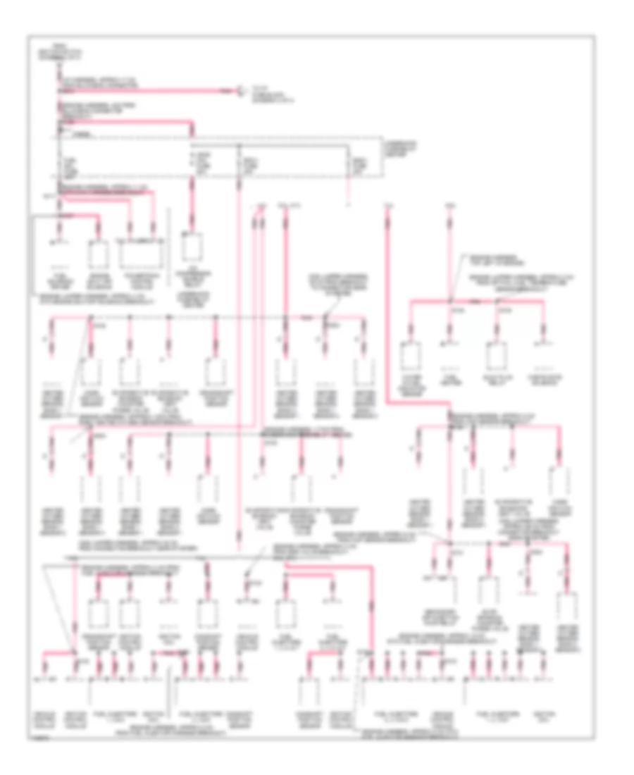
Power Distribution Wiring Diagram (3 of 4) for Chevrolet Chevy Express G3500 1998
 https://portal-diagnostov.com/license.html
Automotive Electricians Portal FZCO
Automotive Electricians Portal FZCO
https://portal-diagnostov.com/license.html
https://portal-diagnostov.com/license.html
Automotive Electricians Portal FZCO
Automotive Electricians Portal FZCOList of elements for Power Distribution Wiring Diagram (3 of 4) for Chevrolet Chevy Express G3500 1998:
- (engine harness, 117cm from underhood fuse-relay center)
- (engine harness, appprox 12cm from right heated oxygen sensor breakout)
- (engine harness, approx 11 cm into main harness breakout)
- (engine harness, approx 15 cm into fuel injector harness breakout)
- (engine harness, approx 4 cm from egr valve breakout) 5.0l, 5.7l
- (engine harness, approx 4 cm from fuel injector harness breakout)
- (engine harness, approx 6 cm from map sensor breakout)
- (engine harness, approx 8 cm from fuel injector harness breakout)
- (engine harness, approx 8 cm into fuel injector harness breakout)
- (engine harness, top left of engine)
- (engine jumper harness, approx 2 cm from optical fuel temperature sensor breakout)
- (engine jumper harness, approx 4 cm into engine shutoff solenoid breakout)
- (i/p harness, approx 17 cm from bulkhead connector) s214
- (o2s jumper harness, 35 cm from breakout to connector near starter)
- (o2s jumper harness, approx 22 cm from connector breakout near starter)
- (o2s jumper harness, approx 66 cm from connector breakout near starter)
- 4.3l
- 5.0l, 5.7l
- 6.5l
- 7.4l
- A/c compressor enable relay
- C11
- C12
- Camshaft position sensor
- Crankshaft position sensor
- Diesel
- Ecm-1 fuse 20a
- Eng-1 fuse 20a
- Engine shut off solenoid
- Evap emission canister purge valve
- Evaporative emission canister purge valve
- Evaporative emission vent valve
- Evaporative emissions vent valve
- From ignition switch (diagram 1 of 4)
- Fuel heater
- Fuel injectors 1, 3 & 5
- Fuel injectors 1, 3, 5 & 7
- Fuel injectors 1, 3, 5, & 7
- Fuel injectors 2, 4 & 6
- Fuel injectors 2, 4, 6 & 8
- Fuel injectors 2, 4, 6, & 8
- Fuel sol fuse 20a
- Fuel solenoid driver
- Glow plug relay
- Heated oxygen sensor, bank 1 sensor 1
- Heated oxygen sensor, bank 1 sensor 2
- Heated oxygen sensor, bank 1 sensor 3
- Heated oxygen sensor, bank 2 sensor 1
- Heated oxygen sensor, bank 2 sensor 2
- Ign-e mini fuse 20a
- Ignition coil
- Ignition control module
- Mass air flow sensor
- Pnk
- Pnk (engine harness, 4cm from bulkhead connector breakout) s126
- Pnk (engine harness, approx 5 cm from ckp sensor breakout) s130
- Pnk s304
- Powertrain control module
- S107
- S108
- S117 pnk
- S130
- S131
- S132
- S132 pnk
- S133 pnk
- S304
- Secondary air injection pump relay
- To i/p fuse block (diagram 4 of 4)
- Underhood fuse-relay center
- Vehicle control module
- Waste gate solenoid
- Water in fuel indicator sensor
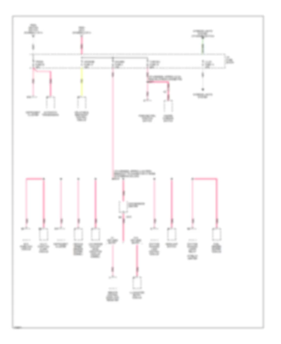
Power Distribution Wiring Diagram (4 of 4) for Chevrolet Chevy Express G3500 1998
 https://portal-diagnostov.com/license.html
Automotive Electricians Portal FZCO
Automotive Electricians Portal FZCO
https://portal-diagnostov.com/license.html
https://portal-diagnostov.com/license.html
Automotive Electricians Portal FZCO
Automotive Electricians Portal FZCOList of elements for Power Distribution Wiring Diagram (4 of 4) for Chevrolet Chevy Express G3500 1998:
- (i/p harness, approx 30 cm from bulkhead connector) s217
- (i/p harness, approx 4 cm from breakout to connector at base of steering column) s216
- Air bags fuse 10 10a
- Automatic transmission
- B10
- B17
- C210
- Convenience center
- Daytime running lamp control module
- Daytime running lamps relay
- Evo passlock module
- From ignition switch (diagram 1 of 4)
- From s214 (diagram 3 of 4)
- Fuel sender buffer module
- Gauges fuse 4 10a
- Hazard warning switch
- Headlamp switch
- I/p fuse block
- I/p relay center
- Illum fuse 14 10a
- Illuminated entry module
- Inflatable restraint control module
- Instrument cluster
- Interior lights system
- Interior lights system (i/p dimmer switch)
- Low engine coolant level indicator module (diesel)
- Multi- function alarm module
- Park/neutral position switch
- Pnk
- Remote control door lock receiver
- Trans fuse 20 10a
- Turn b/u fuse 16 20a
- Vehicle speed sensor buffer (diesel)
- W/ keyless entry
- W/o keyless entry

 Čeština
 Dansk
Dansk Deutsch
 Ελληνικά
 English
 English
 Español
 Suomi
Suomi Français
 Français
 עברית
עברית Hrvatski
 Magyar
 Italiano
 한국어
한국어 Nederlands
 Polski
 Português
 Português
 Română
 Русский
 Slovenčina
 Slovenščina
 Svenska
 Türkçe
 中文 (中国)
