
 Čeština
 Dansk
Dansk Deutsch
 Ελληνικά
 English
 English
 Español
 Suomi
Suomi Français
 Français
 עברית
עברית Hrvatski
 Magyar
 Italiano
 한국어
한국어 Nederlands
 Polski
 Português
 Português
 Română
 Русский
 Slovenčina
 Slovenščina
 Svenska
 Türkçe
 中文 (中国)

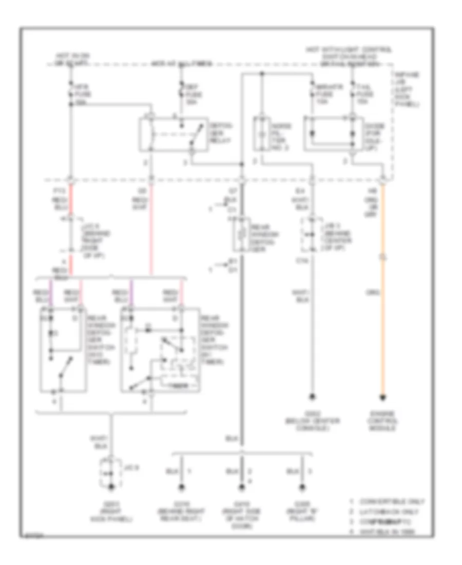
DEFOGGERS
Defogger Wiring Diagram for Toyota Celica GT 1996
List of elements for Defogger Wiring Diagram for Toyota Celica GT 1996:

AIR CONDITIONINGANTI-LOCK BRAKESCRUISE CONTROLEXTERIOR LIGHTSCOOLING FANDEFOGGERSCOMPUTER DATA LINESENGINE PERFORMANCEGROUND DISTRIBUTIONINSTRUMENT CLUSTERPASSIVE RESTRAINTSHORNPOWER ANTENNAPOWER DISTRIBUTIONHEADLIGHTSINTERIOR LIGHTSSUPPLEMENTAL RESTRAINTSPOWER MIRRORSPOWER WINDOWSPOWER DOOR LOCKSSTARTING/CHARGINGSHIFT INTERLOCKSRADIOWARNING SYSTEMSTRANSMISSIONPOWER TOP/SUNROOFWIPER/WASHER