ENGINE PERFORMANCE
2.5L HYBRID
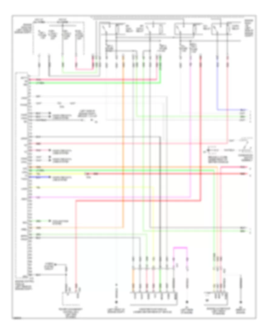
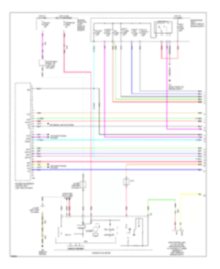
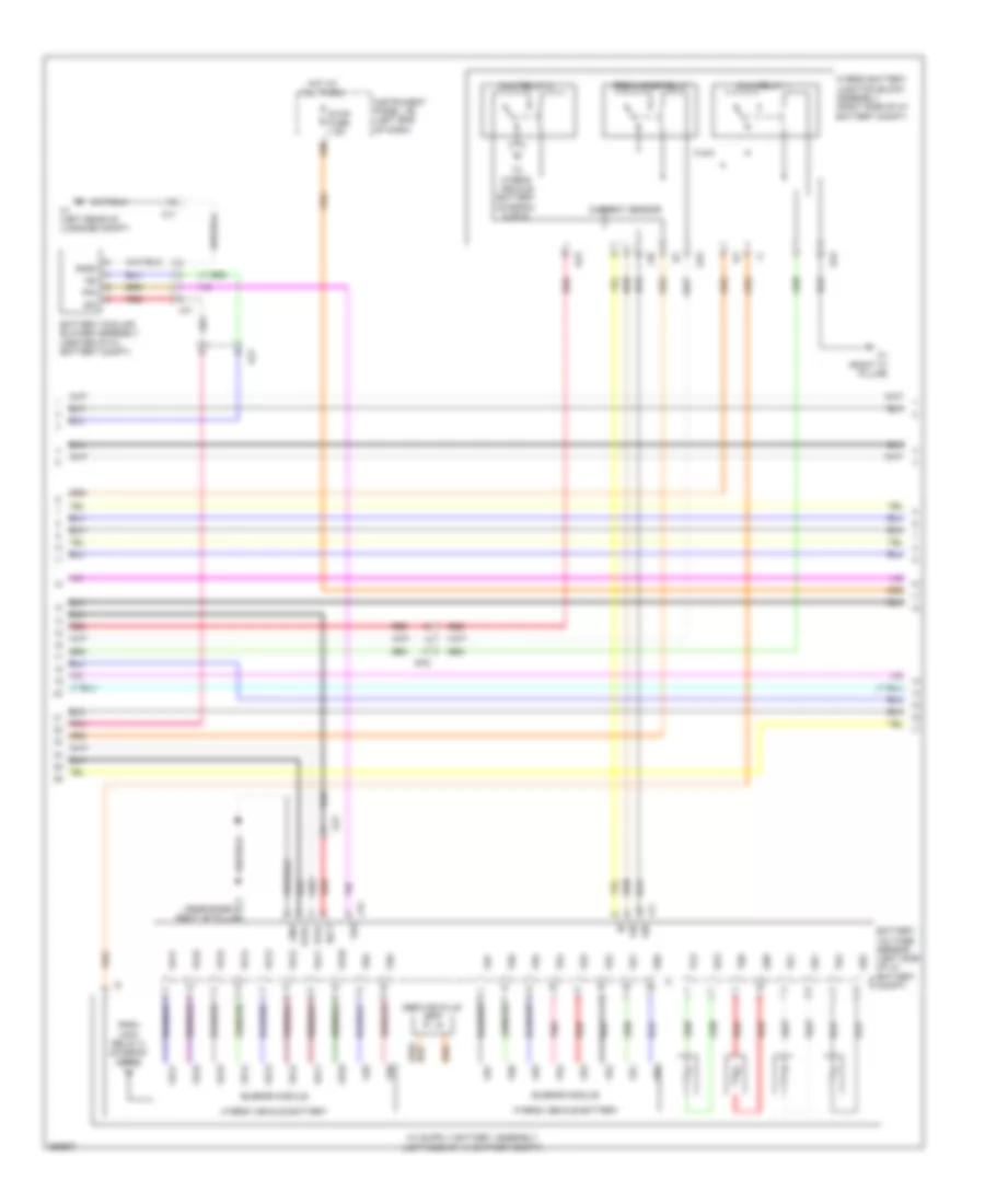
2.5L Hybrid, Engine Controls Wiring Diagram (1 of 4) for Toyota Avalon XLE 2013
 https://portal-diagnostov.com/license.html
Automotive Electricians Portal FZCO
Automotive Electricians Portal FZCO
https://portal-diagnostov.com/license.html
https://portal-diagnostov.com/license.html
Automotive Electricians Portal FZCO
Automotive Electricians Portal FZCO
List of elements for 2.5L Hybrid, Engine Controls Wiring Diagram (1 of 4) for Toyota Avalon XLE 2013:
- (left side of engine compt) ground 1 j/c a47
- +b2
- A1 (left front of engine compt)
- A18
- A53
- A54
- Aj1
- B1 (left rear of engine)
- B2 (rear of engine)
- Ba2
- Batt
- C/opn relay
- C10
- Canh
- Canister pump module (under center rear of vehicle)
- Canl
- Cann
- Canp
- Combination switch assembly
- Computer data line system
- Computer data lines system
- Cooling fans system
- Da2
- Ecu- ig2 3 fuse 7.5a
- Efi 1 fuse 7.5a
- Efi 2 fuse 15a
- Efi 3 fuse 7.5a
- Efi main 2 relay
- Efi main relay
- Efi- main 1 fuse 30a
- Efi- main 2 fuse 20a
- Engine control module (left rear of engine compt)
- Engine room j/b (left side of engine compt)
- Engine room r/b (left side of engine compt)
- Engine water pump (left front of engine)
- Eppm
- G2o
- Ground 2 j/c d96 (under front of center console)
- Hot at all times
- Hybrid system circuit
- Ig 2 relay
- Ig2- main fuse 25a
- Ig2d
- Igsw
- Inj fuse 7.5a
- Mgnd
- Mpmp
- Mrel
- Mtrb
- Nwp
- Pgnd
- Pnk
- Power management control ecu (left end of dash)
- Ppmp
- Pwms
- Red
- Rfc
- Sgnd
- Swp
- Tach
- Vcc
- Vcpp
- Vgnd
- Vlvb
- Vout
- Vpmp
- Wpi
- Wpo
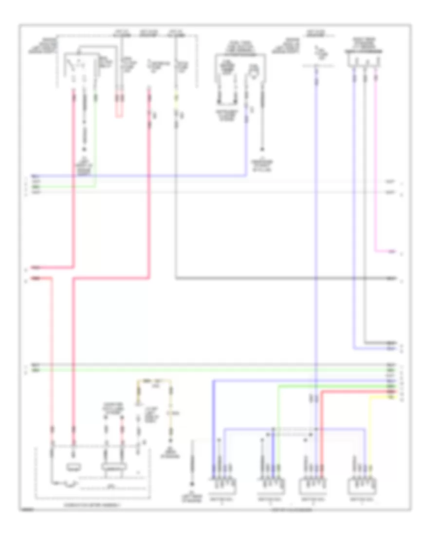
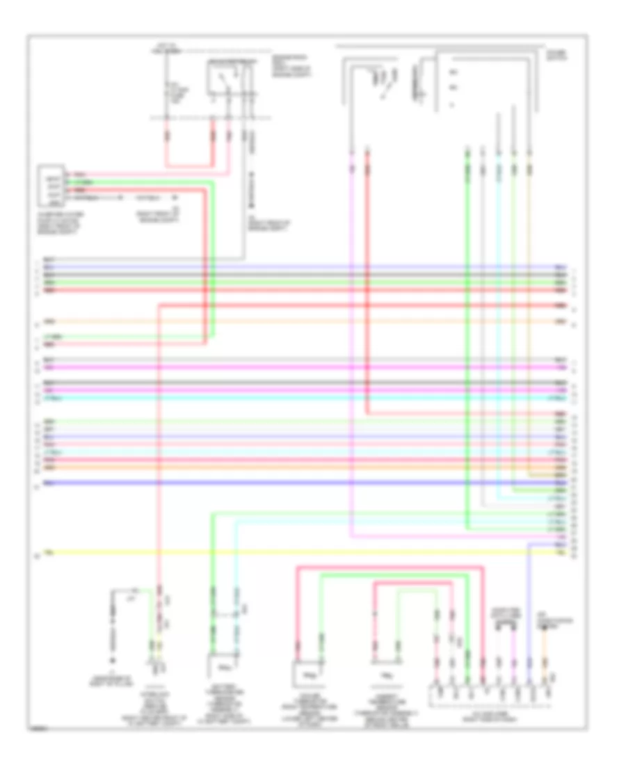
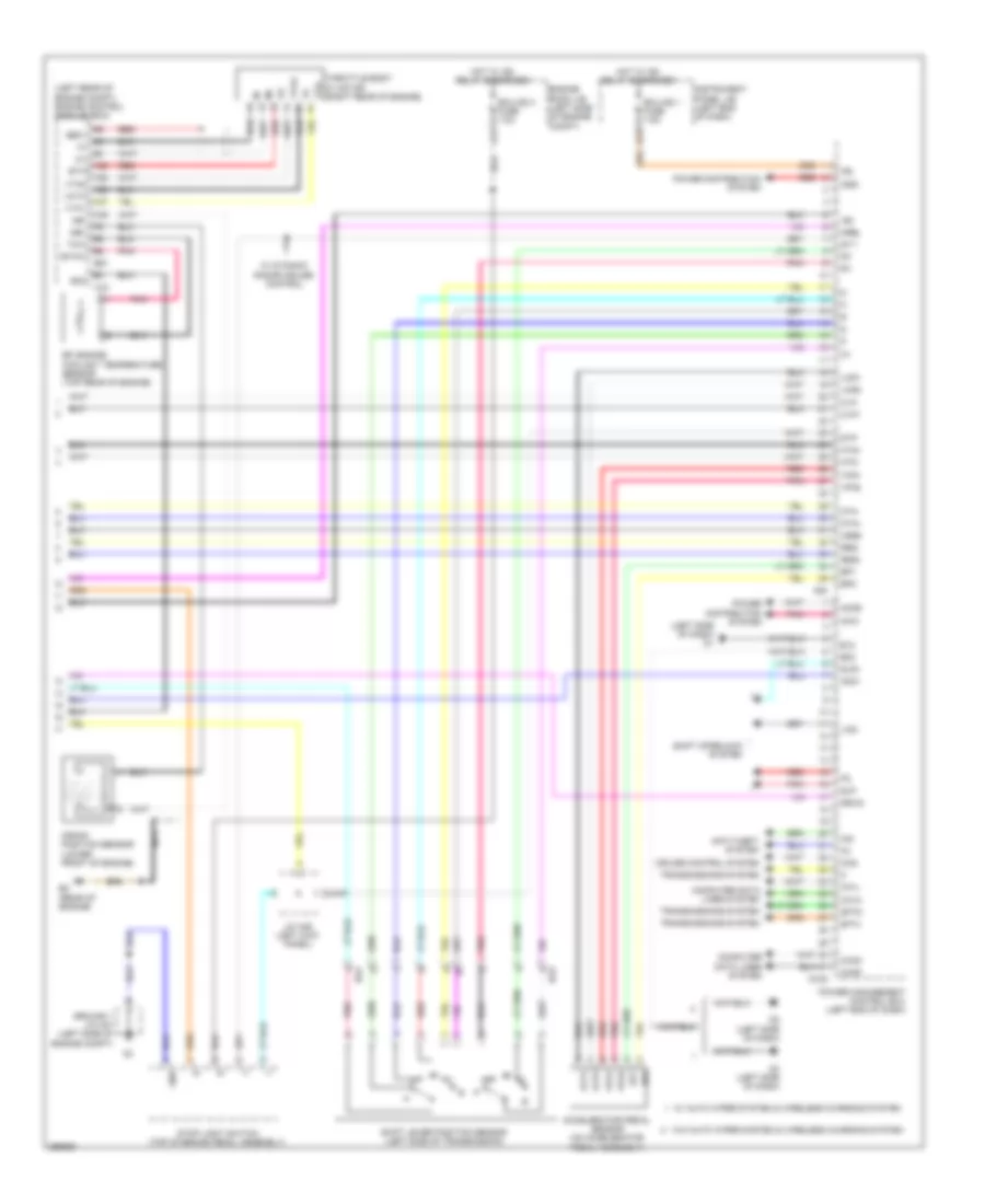
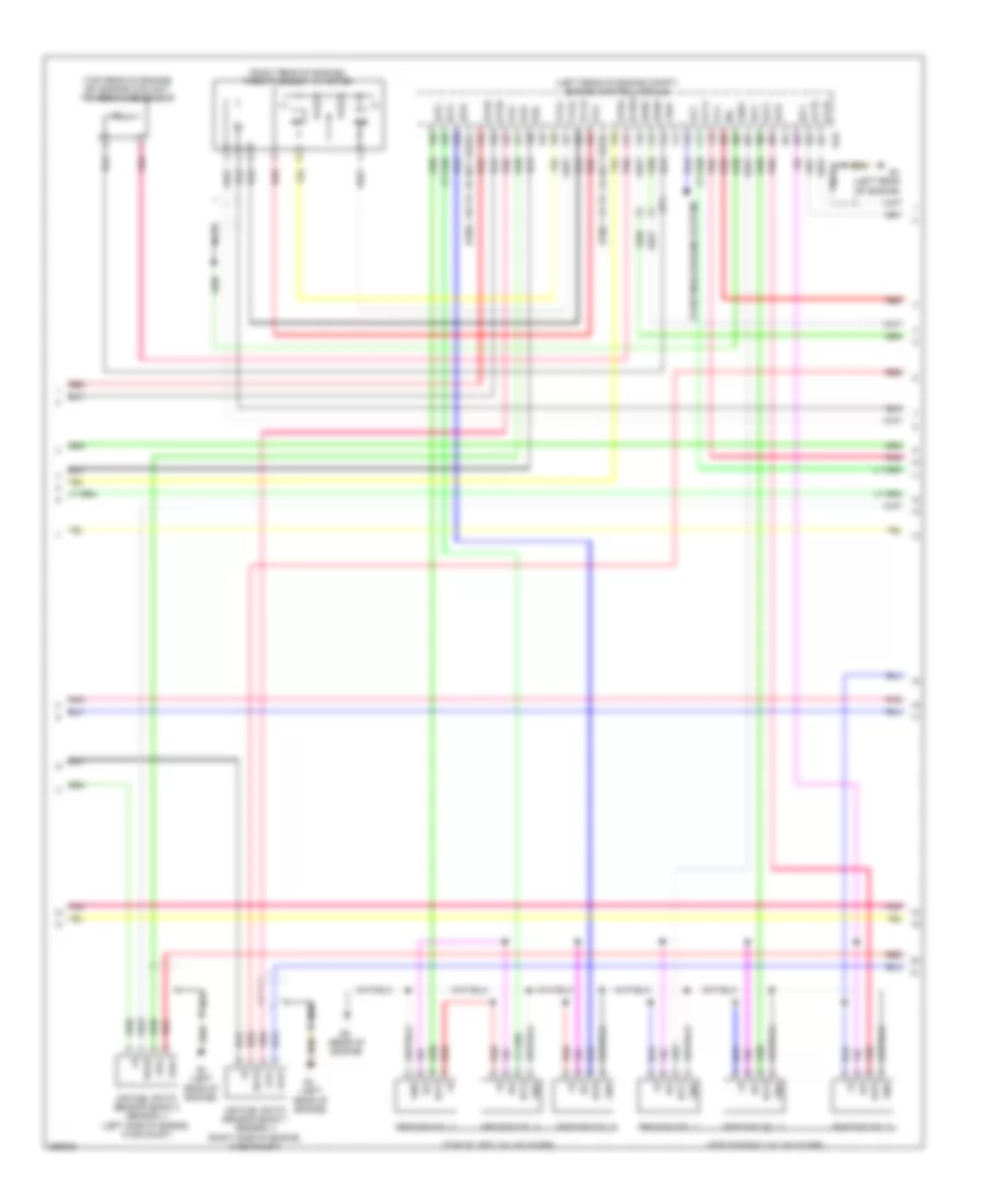
2.5L Hybrid, Engine Controls Wiring Diagram (2 of 4) for Toyota Avalon XLE 2013
 https://portal-diagnostov.com/license.html
Automotive Electricians Portal FZCO
Automotive Electricians Portal FZCO
https://portal-diagnostov.com/license.html
https://portal-diagnostov.com/license.html
Automotive Electricians Portal FZCO
Automotive Electricians Portal FZCOList of elements for 2.5L Hybrid, Engine Controls Wiring Diagram (2 of 4) for Toyota Avalon XLE 2013:
- (fuel tank) fuel suction tube assembly w/ pump & gauge
- (right rear of engine) vvt sensor (bank 1 intake side)
- (top of valve cover)
- 5v ic
- A1 (left front of engine compt)
- Aj1
- B1 (left rear of engine)
- B2 (rear of engine)
- Ba2
- Can i/f
- Canh
- Canl
- Chk
- Combination meter assembly
- Computer data lines system
- Cpu
- Da2
- Ea2
- Eng w/ pmp fuse 30a
- Eng w/ pmp relay
- Engine room j/b (left side of engine compt)
- Engine room r/b (left side of engine compt)
- Etcs fuse 10a
- Fuel pump
- Fuel sender gauge
- Gnd
- Hot at all times
- Hot in on or start
- I/f
- Ig+
- Igf
- Ign fuse 15a
- Ignition coil
- Igt1
- Igt2
- Igt3
- Igt4
- Instrument cluster system
- J/c d97 (left side of dash)
- J1 (near base of right "b" pillar)
- Meter-ig2 fuse 5a
- Pnk
- Red
- Vvi+
- Vvi-
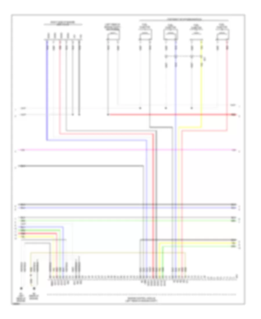
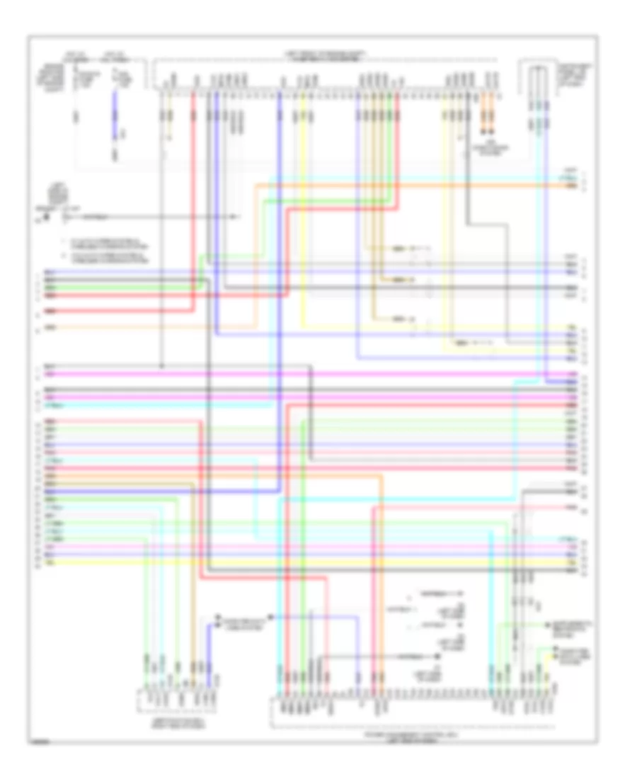
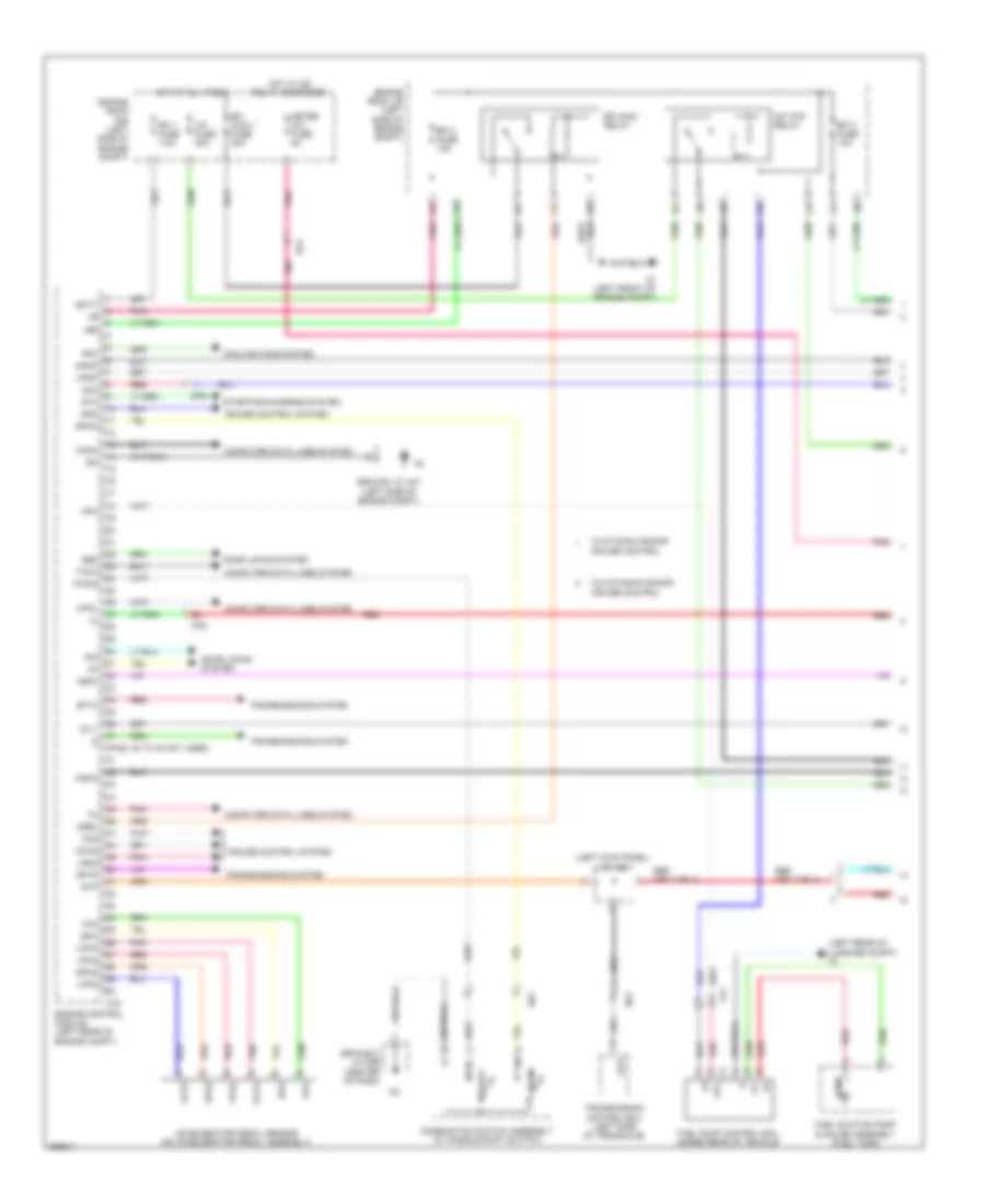
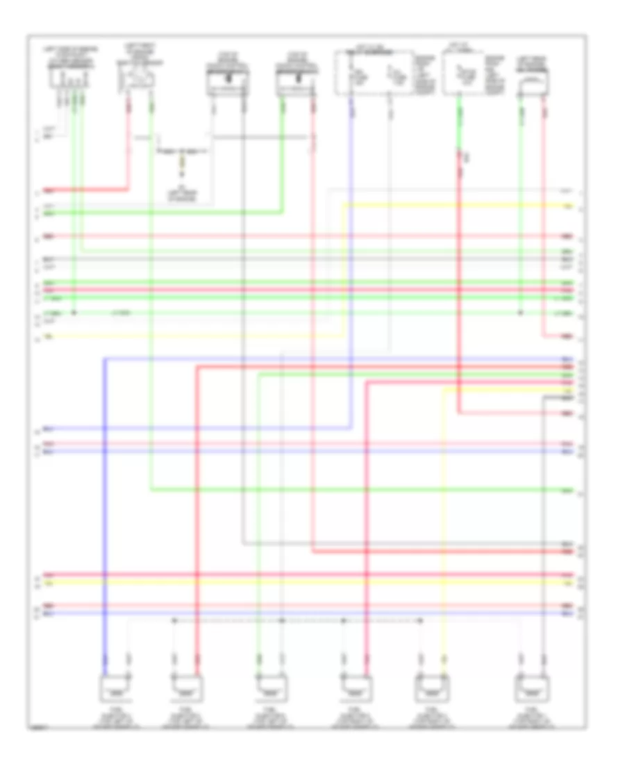
2.5L Hybrid, Engine Controls Wiring Diagram (3 of 4) for Toyota Avalon XLE 2013
 https://portal-diagnostov.com/license.html
Automotive Electricians Portal FZCO
Automotive Electricians Portal FZCO
https://portal-diagnostov.com/license.html
https://portal-diagnostov.com/license.html
Automotive Electricians Portal FZCO
Automotive Electricians Portal FZCOList of elements for 2.5L Hybrid, Engine Controls Wiring Diagram (3 of 4) for Toyota Avalon XLE 2013:
- (left rear of engine compt) vsv (purge)
- (right side of engine) egr valve
- (top right of intake manifold)
- +b1
- +b2
- +bm
- B1 (left rear of engine)
- B2 (rear of engine)
- B51
- Bz1
- E01
- E02
- E04
- Egr1
- Egr2
- Egr3
- Egr4
- Engine control module (left rear of engine compt)
- Fuel injector
- Ha1a
- Ht1b
- Igf1
- Igt1
- Igt2
- Igt3
- Igt4
- Me01
- Red
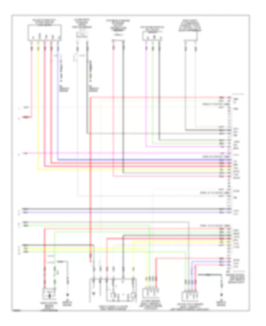
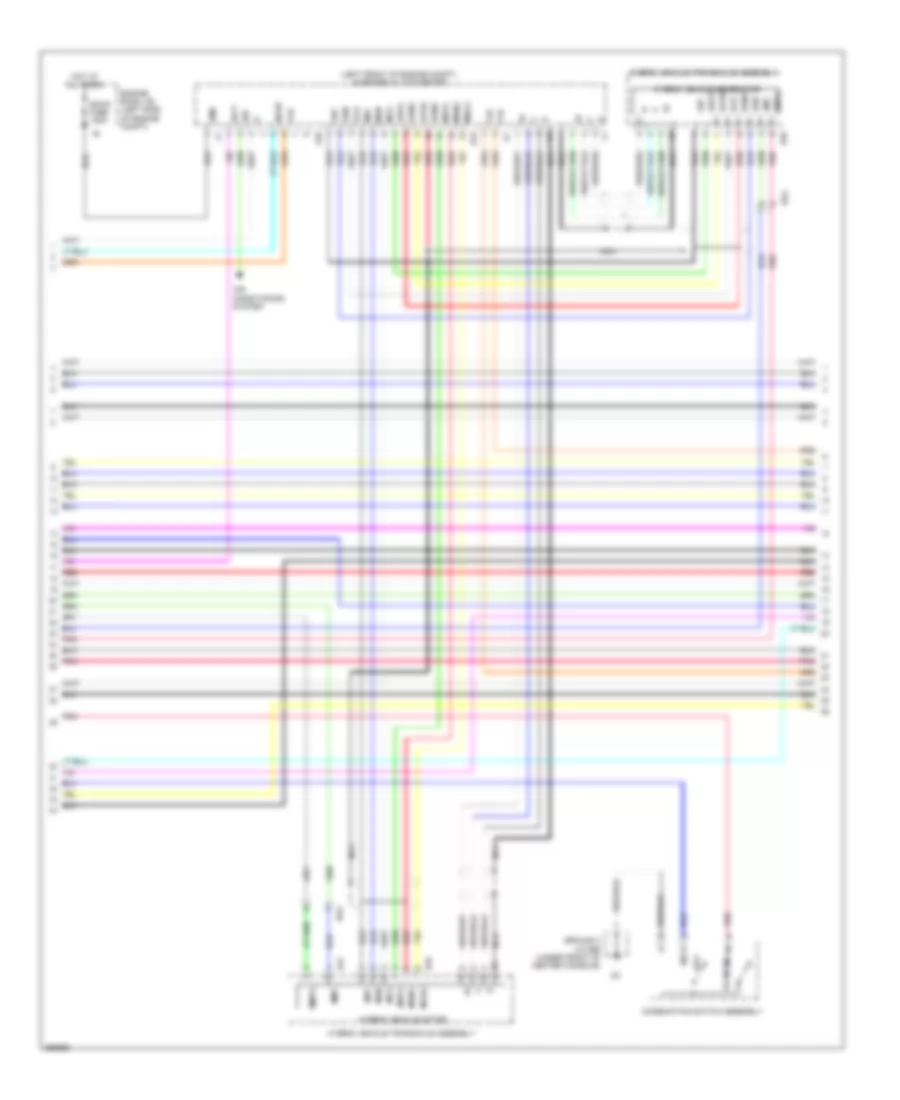
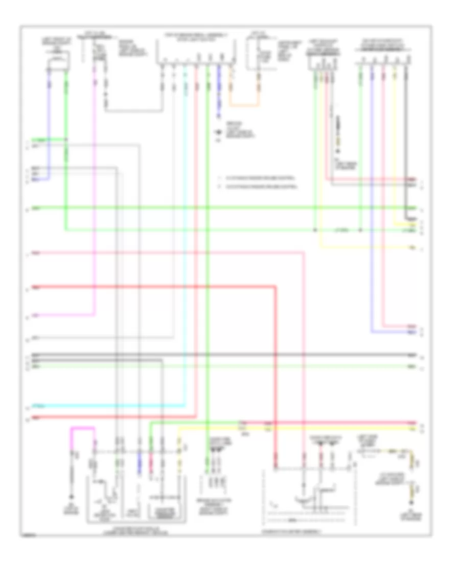
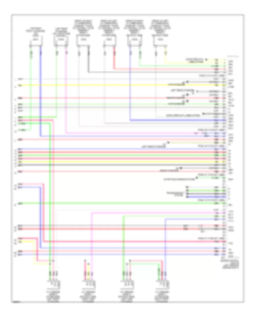
2.5L Hybrid, Engine Controls Wiring Diagram (4 of 4) for Toyota Avalon XLE 2013
 https://portal-diagnostov.com/license.html
Automotive Electricians Portal FZCO
Automotive Electricians Portal FZCO
https://portal-diagnostov.com/license.html
https://portal-diagnostov.com/license.html
Automotive Electricians Portal FZCO
Automotive Electricians Portal FZCOList of elements for 2.5L Hybrid, Engine Controls Wiring Diagram (4 of 4) for Toyota Avalon XLE 2013:
- (lower front of engine) crank position sensor
- (on air intake duct) intake mass air flow meter
- (on intake manifold) efi vacuum sensor
- (pins: 101 to 108 not used)
- (pins: 115 to 122 not used)
- (pins: 61 to 67 not used)
- (pins: 83 to 90 not used)
- (right front cylinder bank) camshaft timing oil control valve (bank 1 intake side)
- (top rear of engine) efi engine coolant temperature sensor
- A1a+
- A1a-
- Air fuel ratio sensor (bank 1 sensor 1) (left rear of engine, in exhaust)
- B2 (rear of engine)
- B51
- Bt1
- E2g
- Eknk
- Engine control module (ecm) (left rear of engine compt)
- Epim
- Eta
- Etha
- Ethw
- Ex1b
- Ge01
- Ha1a
- Ht1b
- Ic1
- Ic2
- Knk1
- Knock control sensor (bank 1) (top of engine)
- Nca
- Ne+
- Ne-
- Oc1+
- Oc1-
- Ox1b
- Oxygen sensor (bank 1 sensor 2) (left side of engine, in exhaust)
- Pim
- Pnk
- Prg
- Red
- Tha
- Throttle body w/ motor (right rear of engine)
- Thw
- Vcpm
- Vcta
- Vcv1
- Vta
- Vta1
- Vta2
- Vv1+
- Vv1-
2.5L Hybrid, Hybrid System Wiring Diagram (1 of 6) for Toyota Avalon XLE 2013
 https://portal-diagnostov.com/license.html
Automotive Electricians Portal FZCO
Automotive Electricians Portal FZCO
https://portal-diagnostov.com/license.html
https://portal-diagnostov.com/license.html
Automotive Electricians Portal FZCO
Automotive Electricians Portal FZCOList of elements for 2.5L Hybrid, Hybrid System Wiring Diagram (1 of 6) for Toyota Avalon XLE 2013:
- +b2
- 5v ic
- A4 (right front of engine compt)
- A53
- Aa1
- Air conditioning system
- B2 (rear of engine)
- B26
- Ba2
- Batt fan fuse 7.5a
- Batt vl ssr fuse 10a
- Buzzer
- Can i/f
- Clk
- Combination meter
- Computer data lines system
- Cpu
- D27
- Da2
- Da6
- Dc/dc igct fuse 10a
- Display driver
- Ecu-b 1 fuse 10a
- Engine room r/b (left side of engine compt)
- Engine room r/b 2 (right side of engine compt)
- Eti
- Exterior lights system
- Gmt
- Gmtg
- Hot at all times
- Hot w/ ig2 relay energized
- I/f
- Igct relay
- Igct- main fuse 25a
- Ilk
- Instrument panel j/b (left end of dash)
- Inv fuse 7.5a
- Inv w/ pmp rly fuse 7.5a
- Ite
- Iwp
- J/c 6
- J/c d97 (left side of dash)
- J/c d98 (center of dash)
- Led driver
- Meter-ig2 fuse 5a
- Mmt
- Mmtg
- Niwp
- Nodd
- Pm igct fuse 7.5a
- Pnk
- Power management control ecu (left end of dash)
- Red
- Sio
- Skid control ecu w/ actuator (brake booster w/ master cylinder assembly) (left rear of engine compt)
- Sp1
- Stb
- Stp2
- Telltales
- Vlo
2.5L Hybrid, Hybrid System Wiring Diagram (2 of 6) for Toyota Avalon XLE 2013
 https://portal-diagnostov.com/license.html
Automotive Electricians Portal FZCO
Automotive Electricians Portal FZCO
https://portal-diagnostov.com/license.html
https://portal-diagnostov.com/license.html
Automotive Electricians Portal FZCO
Automotive Electricians Portal FZCOList of elements for 2.5L Hybrid, Hybrid System Wiring Diagram (2 of 6) for Toyota Avalon XLE 2013:
- +bwp
- A/c amplifier (right side of dash)
- A4 (right front of engine compt)
- Agnd
- Air conditioning system
- Aj3
- Ambient temperature sensor (thermistor assembly) (behind center of front grille)
- Antenna coil
- Battery thermometer sensor (thermistor assembly) (right side of hv battery compt)
- Canh
- Canl
- Computer data lines system
- Cooler thermistor (room temperature sensor) (lower left center of dash)
- D62
- Da6
- Dk2
- Ecos
- Engine room r/b 2 (right side of engine compt)
- Gnd
- Hot at all times
- Ilk
- Interlock switch (service plug grip) (right center front of hv battery compt)
- Inv w/ pmp fuse 15a
- Inv w/ pmp relay
- Inverter water pump w/ motor (right front of engine compt)
- J1 (near base of right "b" pillar)
- Jk1
- Lin1
- Nwp
- Pnk
- Power switch
- Red
- Sg-1
- Sg-2
- Ss1
- Ss2
- Swp
- Tam
2.5L Hybrid, Hybrid System Wiring Diagram (3 of 6) for Toyota Avalon XLE 2013
 https://portal-diagnostov.com/license.html
Automotive Electricians Portal FZCO
Automotive Electricians Portal FZCO
https://portal-diagnostov.com/license.html
https://portal-diagnostov.com/license.html
Automotive Electricians Portal FZCO
Automotive Electricians Portal FZCOList of elements for 2.5L Hybrid, Hybrid System Wiring Diagram (3 of 6) for Toyota Avalon XLE 2013:
- (left front of engine compt) inverter w/ converter
- (left side of engine compt) ground 1 j/c a47
- +b2
- A33
- A34
- A50
- Aa1
- Abfs
- Acpb
- Acpe
- Agnd
- Air conditioning system
- Am2 fuse 7.5a
- Am22
- Bth+
- Bth-
- Ca2h
- Ca2l
- Canh
- Canl
- Certification ecu (right end of dash)
- Clk+
- Clk-
- Code
- Computer data lines system
- D1 (left side of dash)
- D104
- D110
- D16
- D2 (left side of dash)
- D3 (left side of dash)
- Dc/dc-s fuse 7.5a
- Dj2
- Drn1
- Drn2
- Drn3
- Drn4
- Drn5
- Drn8
- E01
- Engine room r/b (left side of engine compt)
- Ethb
- Evsw
- Gnd1
- Gnd2
- Hot at all times
- Hsdn
- Htm+
- Htm-
- I86
- Ilki
- Ilko
- Instrument panel j/b (left end of dash)
- Mth+
- Mth-
- Nca
- Pnk
- Power management control ecu (left end of dash)
- Red
- Req+
- Req-
- Smrb
- Smrg
- Smrp
- Spdi
- Ssw1
- Swil
- Thb
- Txct
- Vc5
- W/ auto wiper system & wireless charging system
- W/o auto wiper system & wireless charging system
2.5L Hybrid, Hybrid System Wiring Diagram (4 of 6) for Toyota Avalon XLE 2013
 https://portal-diagnostov.com/license.html
Automotive Electricians Portal FZCO
Automotive Electricians Portal FZCO
https://portal-diagnostov.com/license.html
https://portal-diagnostov.com/license.html
Automotive Electricians Portal FZCO
Automotive Electricians Portal FZCOList of elements for 2.5L Hybrid, Hybrid System Wiring Diagram (4 of 6) for Toyota Avalon XLE 2013:
- (left front of engine compt) inverter w/ converter
- A49
- Air conditioning system
- Amd
- B43
- B45
- B46
- B47
- Ba2
- Cbi
- Cei
- Combination switch assembly
- Dc/dc fuse 120a
- Drn6
- Eco
- Ecu
- Engine room j/b (left side of engine compt)
- Ev mode
- Gcs
- Gcsg
- Gmt
- Gmtg
- Grf
- Grfg
- Ground 2 j/c d96 (under front of center console)
- Gsn
- Gsng
- Hot at all times
- Hybrid vehicle generator
- Hybrid vehicle motor
- Hybrid vehicle transaxle assembly
- Idh
- Igct
- Mcs
- Mcsg
- Mmt
- Mmtg
- Mrf
- Mrfg
- Mscg
- Msn
- Msng
- Nca
- Nodd
- Pnk
- Red
- Vlo
2.5L Hybrid, Hybrid System Wiring Diagram (5 of 6) for Toyota Avalon XLE 2013
 https://portal-diagnostov.com/license.html
Automotive Electricians Portal FZCO
Automotive Electricians Portal FZCO
https://portal-diagnostov.com/license.html
https://portal-diagnostov.com/license.html
Automotive Electricians Portal FZCO
Automotive Electricians Portal FZCOList of elements for 2.5L Hybrid, Hybrid System Wiring Diagram (5 of 6) for Toyota Avalon XLE 2013:
- Aj3
- Battery cooling blower assembly (center of hv battery compt)
- Battery voltage sensor (left side of hv battery compt)
- Bth+
- Bth-
- Busbar module
- Busbar module hybrid vehicle battery
- Current sensor
- D30
- Dk2
- Fp0
- From main relay 2 (diagram 5 of 6)
- Gb0
- Gb1
- Gb2
- Gbo
- Gc0
- Gib
- Gnd
- Gnd0
- Hot at all times
- Hybrid battery junction block assembly (right side of hv battery compt)
- Hybrid vehicle battery
- Ig0
- Igct
- Instrument panel j/b (left end of dash)
- J1 (near base of right "b" pillar)
- J13
- Jk1
- K1 (right "c" pillar)
- K23
- Main relay 1
- Main relay 2
- O1 (left rear of luggage compt)
- Oj1
- Pnk
- Precharge relay
- Red
- Service plug grip
- Si0
- Stop fuse 7.5a
- Tb0
- Tb1
- Tb2
- Tco
- To hybrid vehicle battery (diagram 5 of 6)
- Vb1
- Vb10
- Vb11
- Vb12
- Vb13
- Vb14
- Vb15
- Vb16
- Vb17
- Vb2
- Vb3
- Vb4
- Vb5
- Vb6
- Vb7
- Vb8
- Vb9
- Vib
- Z10
- Z11
2.5L Hybrid, Hybrid System Wiring Diagram (6 of 6) for Toyota Avalon XLE 2013
 https://portal-diagnostov.com/license.html
Automotive Electricians Portal FZCO
Automotive Electricians Portal FZCO
https://portal-diagnostov.com/license.html
https://portal-diagnostov.com/license.html
Automotive Electricians Portal FZCO
Automotive Electricians Portal FZCOList of elements for 2.5L Hybrid, Hybrid System Wiring Diagram (6 of 6) for Toyota Avalon XLE 2013:
- (left rear of engine compt) engine control module (ecm)
- (left side of dash) d1
- +b1
- A18
- A54
- Accd
- Accelerator pedal sensor (on accelerator pedal assembly)
- Am21
- Anti-theft system
- B2 (rear of engine)
- B51
- Ba2
- Ba3
- Ca1h
- Ca1l
- Ca3n
- Ca3p
- Ccs
- Clk+
- Clk-
- Computer data lines system
- Crank position sensor (lower front of engine)
- Cruise control system
- D105
- D2 (left side of dash)
- D23
- D3 (left side of dash)
- E02
- E12
- Ecu-ig2 1 fuse 7.5a
- Ecu-ig2 3 fuse 7.5a
- Efi engine coolant temperature sensor (top rear of engine)
- Engine room j/b (left side of engine compt)
- Ep1
- Ep2
- Eta
- Ethw
- G2o
- Ge01
- Gnd
- Ground 1 j/c a47 (left side of engine compt)
- Hot w/ ig2 relay energized
- Hsdn
- Htm+
- Htm-
- Ig1d
- Ig2
- Ig2d
- Imi
- Imo
- Instrument panel j/b (left end of dash)
- J/c a46 (left kick panel)
- Lin2
- Mrel
- Mth+
- Mth-
- Nca
- Ne+
- Ne-
- Pnk
- Power distribution system
- Power management control ecu (left end of dash)
- Red
- Req+
- Req-
- Sft4
- Sftd
- Shift interlock system
- Shift lever position sensor (left side of transmission)
- Slp
- Slr+
- Ssw2
- St1-
- Stop light switch (top of brake pedal assembly)
- Stp
- Throttle body w/ motor (right rear of engine)
- Thw
- Transmissions system
- Vcp1
- Vcp2
- Vcta
- Vpa1
- Vpa2
- Vta
- Vta1
- Vta2
- W/ auto wiper system & wireless charging system
- W/ dynamic radar cruise control
- W/o auto wiper system & wireless charging system
3.5L
3.5L, Engine Performance Wiring Diagram (1 of 5) for Toyota Avalon XLE 2013
 https://portal-diagnostov.com/license.html
Automotive Electricians Portal FZCO
Automotive Electricians Portal FZCO
https://portal-diagnostov.com/license.html
https://portal-diagnostov.com/license.html
Automotive Electricians Portal FZCO
Automotive Electricians Portal FZCOList of elements for 3.5L, Engine Performance Wiring Diagram (1 of 5) for Toyota Avalon XLE 2013:
- (left kick panel) j/c a46
- (left rear of luggage compt) j2
- (pins: 38 to 40 not used)
- +b2
- A/f fuse 20a
- A/f htr relay
- A1 (left front of engine compt)
- A18
- Accelerator pedal sensor (on accelerator pedal assembly)
- Acm
- Aj1
- Ba2
- Batt
- C10
- Canh
- Canl
- Cchg
- Ccs
- Combination switch assembly (w/ paddle shift switch)
- Computer data lines system
- Cooling fans system
- Cruise control system
- Da2
- Door locks system
- Efi 1 fuse 7.5a
- Efi 2 fuse 15a
- Efi 3 fuse 10a
- Efi main 1 fuse 30a
- Efi main relay
- Engine control module (left rear of engine compt)
- Engine room j/b (left side of engine compt)
- Engine room r/b (left side of engine compt)
- Epa
- Epa2
- Fp-
- Fpc
- Fuel pump control ecu (under rear of vehicle)
- Fuel suction pump & gauge assembly (fuel tank)
- Ground 2 j/c d96 (center of dash)
- Ground j/c a47 (left side of engine compt)
- Hot at all times
- Hot w/ ig2 relay energized
- Igsw
- Imi
- Imo
- Lgnd
- Meter ig 2 fuse 5a
- Mpmp
- Mrel
- Neo
- Norm
- Pnk
- Ppmp
- Pump
- Pwms
- Pwr
- Red
- Rfc
- Sftd
- Sftu
- Spcn
- Spd
- Sport
- St1-
- Sta
- Starting/charging system
- Stp
- Tach
- Transmission control ecu (left side of transaxle)
- Transmissions system
- Vcp2
- Vcpa
- Vpa
- Vpa2
- Vpmp
- W/ dynamic radar cruise control
- W/o dynamic radar cruise control
3.5L, Engine Performance Wiring Diagram (2 of 5) for Toyota Avalon XLE 2013
 https://portal-diagnostov.com/license.html
Automotive Electricians Portal FZCO
Automotive Electricians Portal FZCO
https://portal-diagnostov.com/license.html
https://portal-diagnostov.com/license.html
Automotive Electricians Portal FZCO
Automotive Electricians Portal FZCOList of elements for 3.5L, Engine Performance Wiring Diagram (2 of 5) for Toyota Avalon XLE 2013:
- (left exhaust manifold) oxygen sensor (bank 2 sensor 2)
- (left front of engine compt) vsv (acm)
- (left side of dash) j/c d97
- (on air intake duct) intake mass air flow meter sub-assembly
- (top of brake pedal assembly) stop light switch
- 5v ic
- A45
- Acc
- Aj1
- B1 (left rear of engine)
- B2 (top of engine)
- B42
- Ba2
- Brake actuator assembly (right side of engine compt)
- Can if
- Canh
- Canister pressure sensor
- Canister pump module (under center rear of vehicle)
- Canl
- Combination meter assembly
- Computer data lines system
- Cpu
- D30
- Da2
- E2g
- Ecu ig2 3 fuse 7.5a
- Engine room j/b (left side of engine compt)
- Gnd
- Ground j/c a47 (left side of engine compt)
- Hot at all times
- Hot w/ ig2 relay energized
- Ht2b
- I/f
- Instrument panel j/b (left end of dash)
- J/c a45 & b42 (left side of engine compt)
- Leak detection pump
- Nca
- Out
- Ox2b
- Pnk
- Red
- Stop fuse 7.5a
- Stpo
- Tha
- Vent valve
- W/ dynamic radar cruise control
- W/o dynamic radar cruise control
3.5L, Engine Performance Wiring Diagram (3 of 5) for Toyota Avalon XLE 2013
 https://portal-diagnostov.com/license.html
Automotive Electricians Portal FZCO
Automotive Electricians Portal FZCO
https://portal-diagnostov.com/license.html
https://portal-diagnostov.com/license.html
Automotive Electricians Portal FZCO
Automotive Electricians Portal FZCOList of elements for 3.5L, Engine Performance Wiring Diagram (3 of 5) for Toyota Avalon XLE 2013:
- (left rear of engine compt) engine control module
- (left rear of engine)
- (pins: 119 to 124 not used)
- (pins: 135 to 137 not used)
- (rear of engine)
- (right rear of engine) throttle body w/ motor
- (top of left valve cover)
- (top of right valve cover)
- (top rear of engine) efi engine coolant temperature sensor
- A1a+
- A1a-
- A2a+
- A2a-
- Air fuel ratio sensor (bank 1 sensor 1) (right side of engine, in exhaust)
- Air fuel ratio sensor (bank 2 sensor 1) (left side of engine, in exhaust)
- Alt
- B1 (left rear of engine)
- B10
- Bt1
- E2g
- Ekn2
- Eknk
- Eta
- Etha
- Ethw
- Ex1b
- Ex2b
- Ge01
- Gnd
- Ha1a
- Ha2a
- Ic1
- Ic2
- Igf
- Igf1
- Ignition coil 1
- Ignition coil 2
- Ignition coil 3
- Ignition coil 4
- Ignition coil 5
- Ignition coil 6
- Igt1
- Igt2
- Igt3
- Igt4
- Igt5
- Igt6
- Nca
- Ne-
- Ox1b
- Ox2b
- Pnk
- Red
- Starting/charging system
- Thw
- Vcta
- Vcv1
- Vta1
- Vta2
- Vv1-
3.5L, Engine Performance Wiring Diagram (4 of 5) for Toyota Avalon XLE 2013
 https://portal-diagnostov.com/license.html
Automotive Electricians Portal FZCO
Automotive Electricians Portal FZCO
https://portal-diagnostov.com/license.html
https://portal-diagnostov.com/license.html
Automotive Electricians Portal FZCO
Automotive Electricians Portal FZCOList of elements for 3.5L, Engine Performance Wiring Diagram (4 of 5) for Toyota Avalon XLE 2013:
- (left front of engine) crank position sensor
- (left rear of engine) vsv (purge)
- (left side of engine compt)
- (left side of engine, in exhaust) oxygen sensor (bank 1 sensor 2)
- (top of engine) knock control sensor (bank 1)
- (top of engine) knock control sensor (bank 2)
- B1 (left rear of engine)
- Ba2
- Engine room j/b
- Engine room r/b (left side of engine compt)
- Etcs fuse 10a
- Fuel injector 1 (top right of intake manifold)
- Fuel injector 2 (top left of intake manifold)
- Fuel injector 3 (top right of intake manifold)
- Fuel injector 4 (top left of intake manifold)
- Fuel injector 5 (top right of intake manifold)
- Fuel injector 6 (top left of intake manifold)
- Hot at all times
- Hot w/ ig2 relay energized
- Ht1b
- Ign fuse 15a
- Inj fuse 7.5a
- Nca
- Ox1b
- Pnk
- Red
3.5L, Engine Performance Wiring Diagram (5 of 5) for Toyota Avalon XLE 2013
 https://portal-diagnostov.com/license.html
Automotive Electricians Portal FZCO
Automotive Electricians Portal FZCO
https://portal-diagnostov.com/license.html
https://portal-diagnostov.com/license.html
Automotive Electricians Portal FZCO
Automotive Electricians Portal FZCOList of elements for 3.5L, Engine Performance Wiring Diagram (5 of 5) for Toyota Avalon XLE 2013:
- (front of left cylinder bank) camshaft timing oil control valve assembly (bank 2 exhaust side)
- (front of left cylinder bank) camshaft timing oil control valve assembly (bank 2 intake side)
- (front of right cylinder bank) camshaft timing oil control valve assembly (bank 1 exhaust side)
- (front of right cylinder bank) camshaft timing oil control valve assembly (bank 1 intake side)
- (left rear of engine)
- (left rear of engine) vsv (air intake control)
- (pins: 36 to 45 not used)
- (pins: 50 to 52 not used)
- (pins: 6 to 19 not used)
- (pins: 61 to 64 not used)
- (pins: 72 to 75 not used)
- (pins: 87 to 95 not used)
- (top right front of engine) vsv (acis)
- +bm
- A1a+
- A2a+
- Acis
- Aicv
- B1 (left rear of engine)
- B10
- B2 (top of engine)
- B3 (rear of engine)
- Ba2
- Bt1
- Can+
- Can-
- Computer data lines system
- E01
- E02
- E04
- E05
- Engine control module (left rear of engine compt)
- Ev1+
- Ev2+
- Ex+
- Ex-
- Ha1a
- Ha2a
- Ht1b
- Ht2b
- Knk1
- Knk2
- Me01
- Ne+
- Nsw
- Oc1+
- Oc1-
- Oc2+
- Oc2-
- Oe1+
- Oe1-
- Oe2+
- Oe2-
- Pnk
- Prg
- Red
- Starting/charging system
- Tha
- Transmissions system
- Vc2
- Vv1+
- Vv2+
- Vvl+
- Vvl-
- Vvr+
- Vvr-
- Vvt sensor (bank 1 exhaust side) (right side of engine)
- Vvt sensor (bank 1 intake side) (right front of engine)
- Vvt sensor (bank 2 exhaust side) (left side of engine)
- Vvt sensor (bank 2 intake side) (left front of engine)

 Čeština
 Dansk
Dansk Deutsch
 Ελληνικά
 English
 English
 Español
 Suomi
Suomi Français
 Français
 עברית
עברית Hrvatski
 Magyar
 Italiano
 한국어
한국어 Nederlands
 Polski
 Português
 Português
 Română
 Русский
 Slovenčina
 Slovenščina
 Svenska
 Türkçe
 中文 (中国)
