ENGINE PERFORMANCE
4.0L
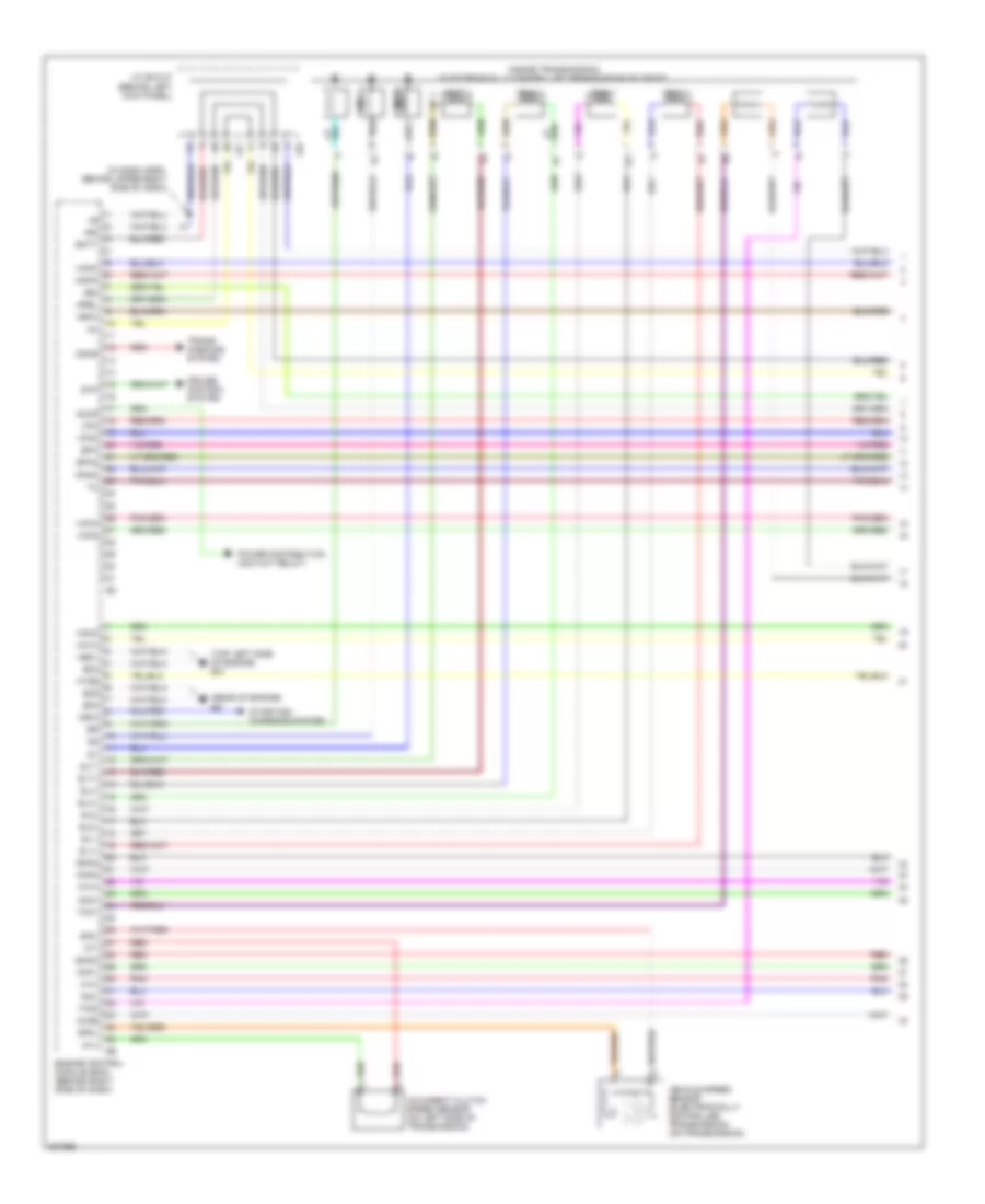
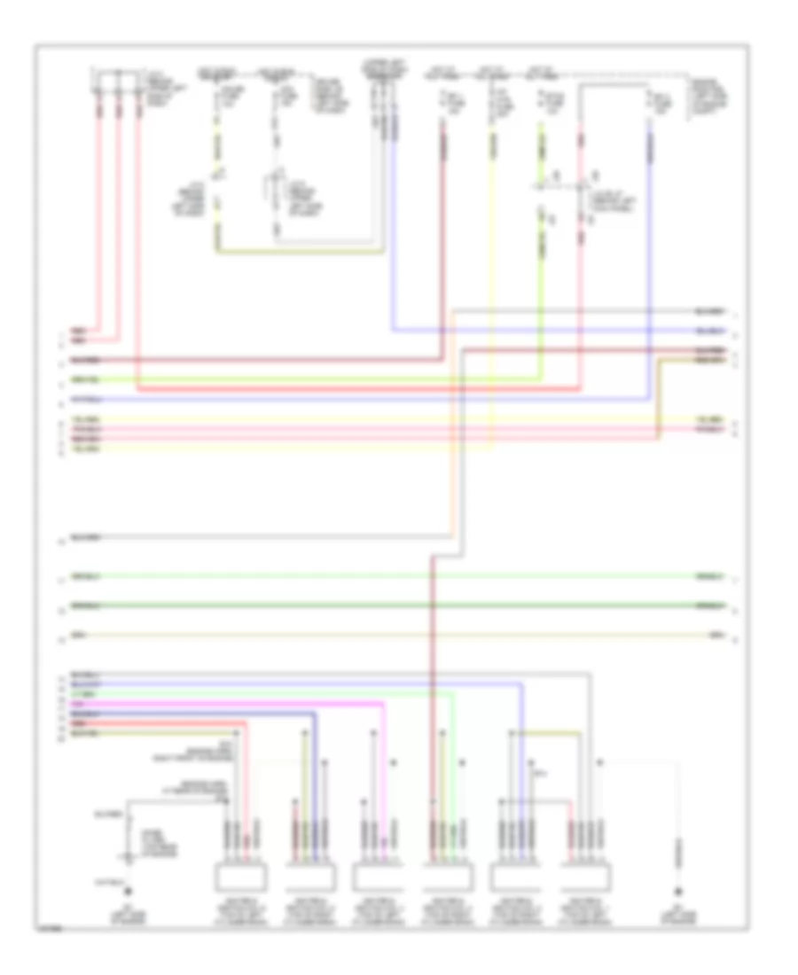
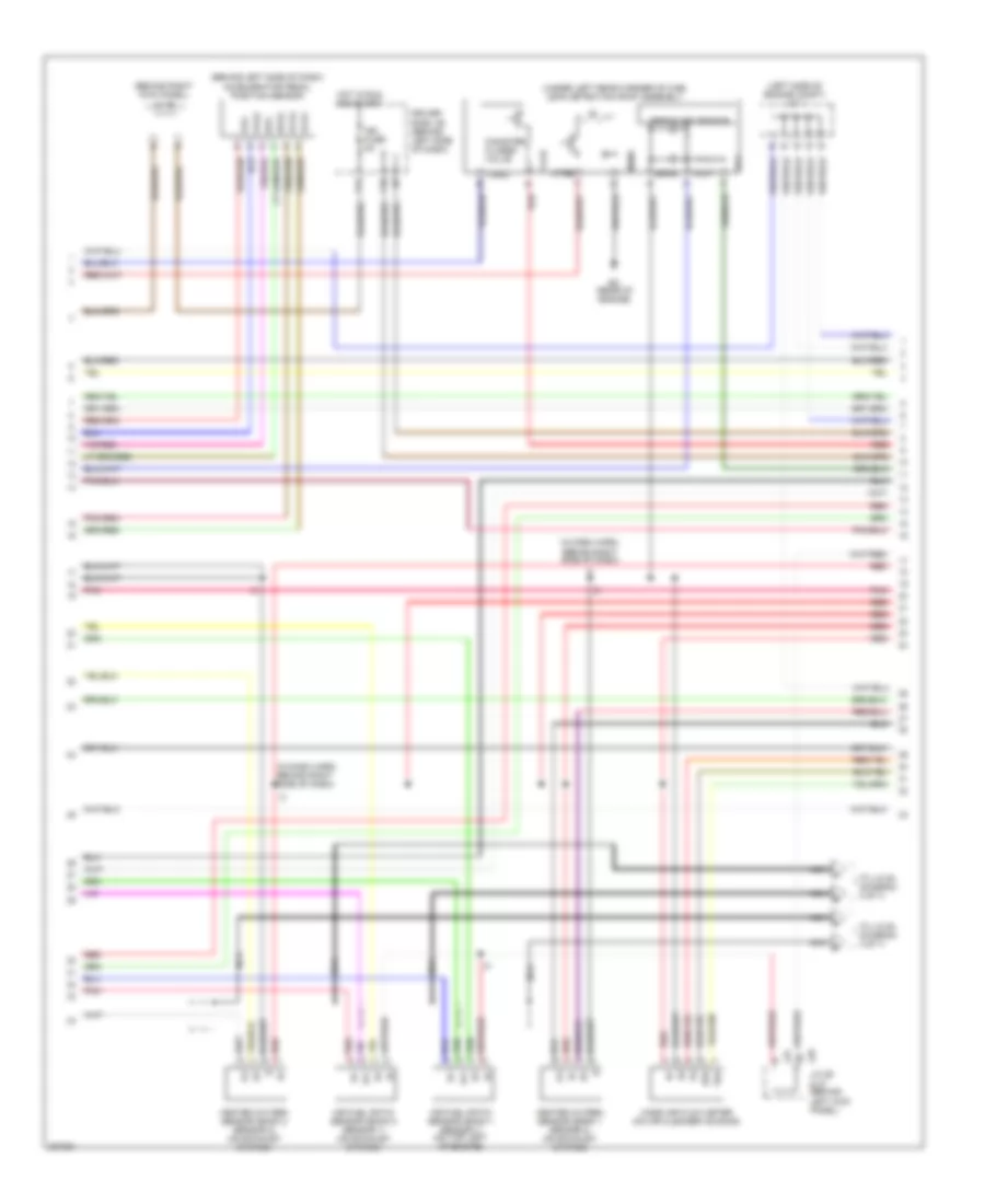
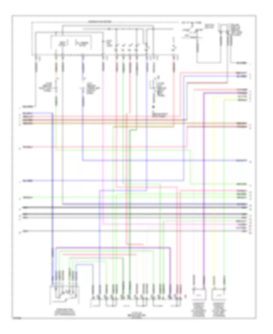
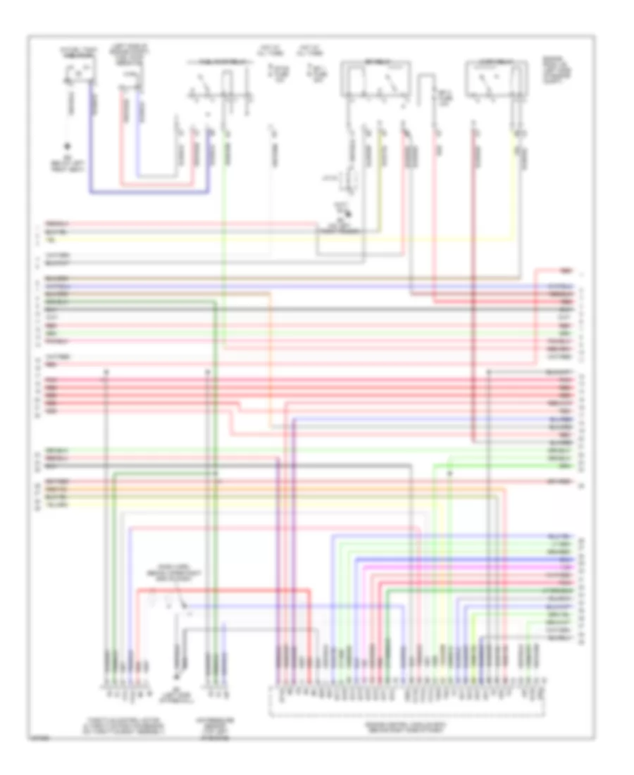
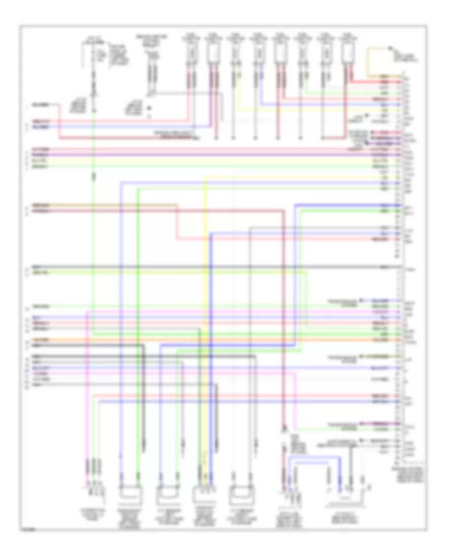
4.0L, Engine Performance Wiring Diagram (1 of 7) for Toyota Tundra 2005
 https://portal-diagnostov.com/license.html
Automotive Electricians Portal FZCO
Automotive Electricians Portal FZCO
https://portal-diagnostov.com/license.html
https://portal-diagnostov.com/license.html
Automotive Electricians Portal FZCO
Automotive Electricians Portal FZCO
List of elements for 4.0L, Engine Performance Wiring Diagram (1 of 7) for Toyota Tundra 2005:
- (in dash harn, behind upper right side of dash)
- (inside transmission) electronically controlled transmission solenoid
- (rear of engine) ec
- (top left side of engine) ew
- +b2
- +bm
- A1a+
- A1a-
- A2a+
- A2a-
- Accr
- Batt
- Cruise control system
- E03
- E04
- E05
- Ekn2
- Eknk
- Engine control module (ecm) (behind right side of dash)
- Epa
- Epa2
- Ha1a
- Ha2a
- Ht2b
- Igsw
- J/c 26 & 27 (behind left kick panel)
- J26
- J27
- Knk1
- Knk2
- Me01
- Mpmp
- Mrel
- No 1
- No 2
- Nsw
- Nt+
- Nt-
- O/d direct clutch speed sensor (on left side of transmission)
- Odms
- Ox2b
- Pnk
- Power distribution (acc cut relay)
- Ppmp
- Red
- Sl1
- Sl1+
- Sl1-
- Sl2
- Sl2+
- Sl2-
- Slt
- Slt+
- Slt-
- Slu
- Slu+
- Slu-
- Sp2+
- Sp2-
- Starting/ charging system
- Stp
- Th02
- Tho1
- Trans- missions system
- Vcp2
- Vcpa
- Vehicle speed sensor (electronically controlled transmission) (on transmission)
- Vpa
- Vpa2
- Vpmp
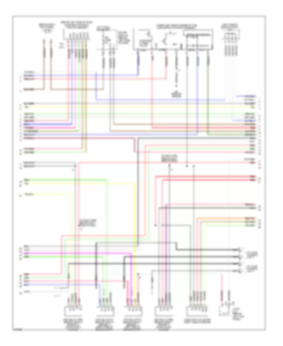
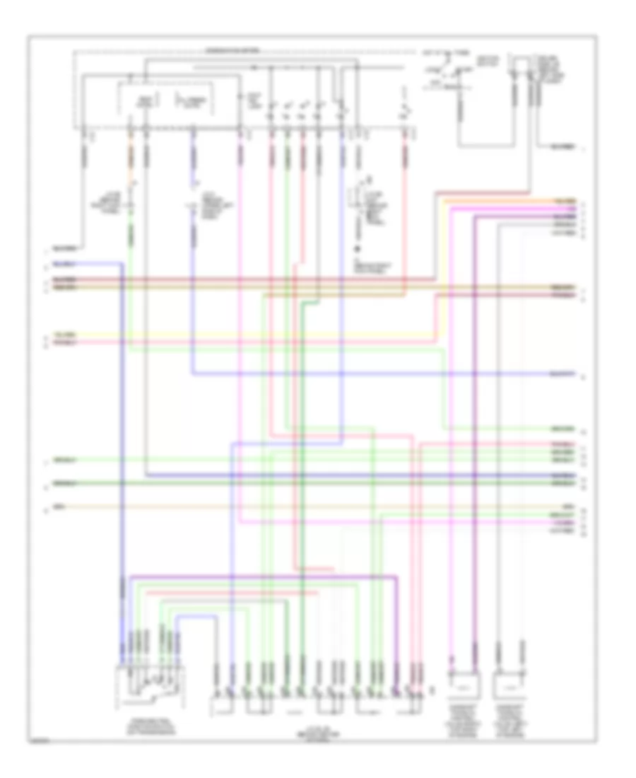
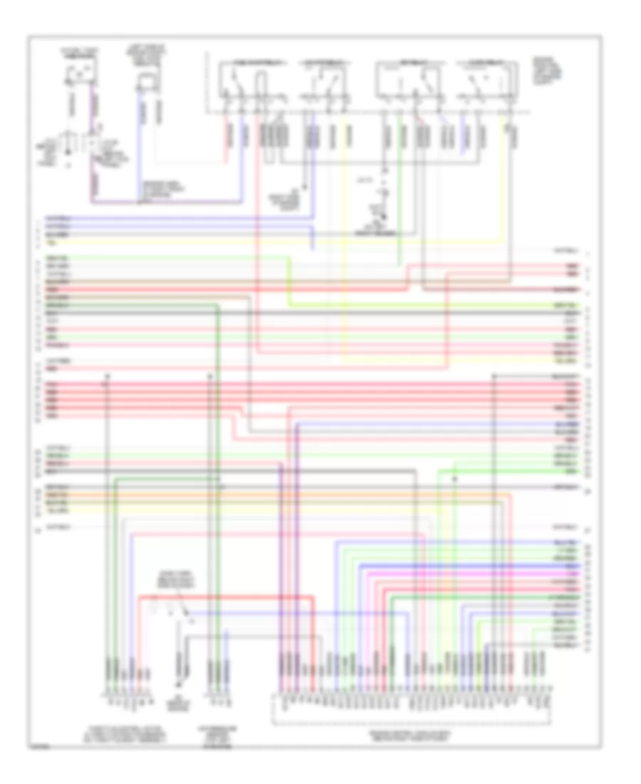
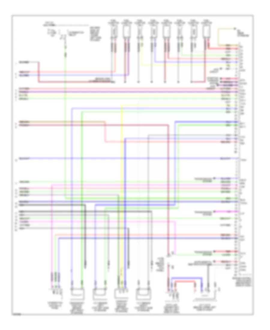
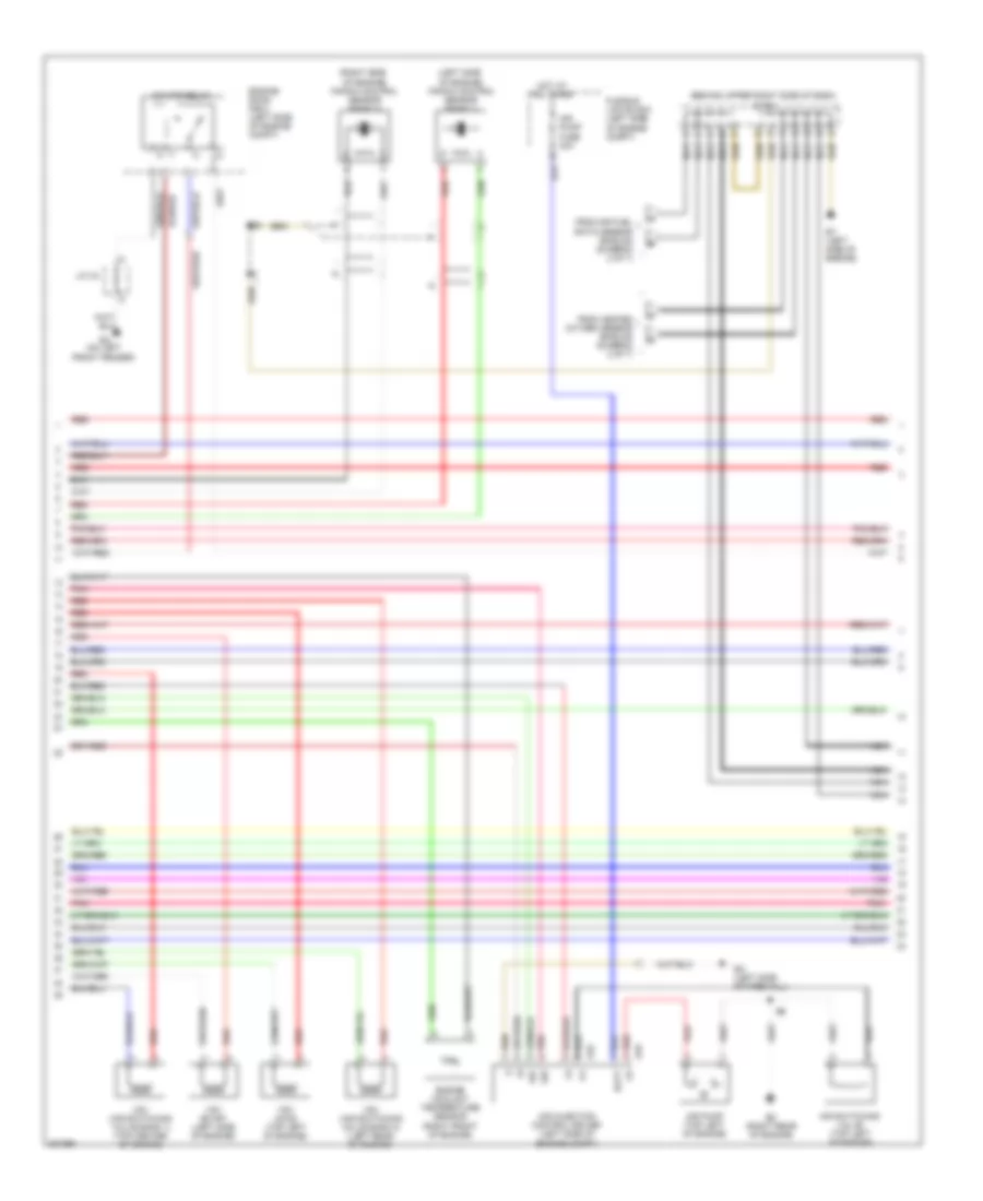
4.0L, Engine Performance Wiring Diagram (2 of 7) for Toyota Tundra 2005
 https://portal-diagnostov.com/license.html
Automotive Electricians Portal FZCO
Automotive Electricians Portal FZCO
https://portal-diagnostov.com/license.html
https://portal-diagnostov.com/license.html
Automotive Electricians Portal FZCO
Automotive Electricians Portal FZCOList of elements for 4.0L, Engine Performance Wiring Diagram (2 of 7) for Toyota Tundra 2005:
- (a/t)
- (behind left side of dash) accelerator pedal position sensor
- (behind right kick panel) j/c 66
- (in dash harn, behind right side of dash)
- (left side of engine compt) j/c 1
- (m/t)
- (under left rear corner of cab) leak detection pump assembly
- Af+
- Af-
- Air fuel ratio sensor (bank 1 sensor 1) (left side of engine compt)
- Air fuel ratio sensor (bank 2 sensor 1) (right side of engine compt)
- Canister closed valve
- Driver side j/b (behind left side of dash)
- E2g
- Ec (rear of engine)
- Epa
- Epa2
- F10
- F11
- Heated oxygen sensor (bank 1 sensor 2) (on exhaust system)
- Heated oxygen sensor (bank 2 sensor 2) (on exhaust system)
- Hot in run and start
- Ign fuse 5a
- J26 j/c 26 & 27 (behind left kick panel)
- J27
- Mass air flow meter (right side of engine)
- Mgnd
- Mtrb
- Nca
- Nca a
- Nca b
- Nca c
- Nca d
- Pnk
- Pressure sensor
- Red
- Sgnd
- Tha
- To j/c 65 (diagram 4 of 7)
- Vcc
- Vcp2
- Vcpa
- Vgnd
- Vlvb
- Vout
- Vpa
- Vpa2
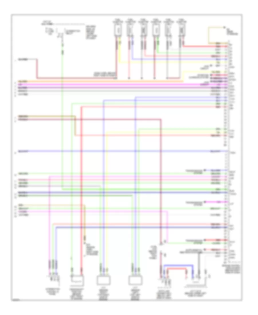
4.0L, Engine Performance Wiring Diagram (3 of 7) for Toyota Tundra 2005
 https://portal-diagnostov.com/license.html
Automotive Electricians Portal FZCO
Automotive Electricians Portal FZCO
https://portal-diagnostov.com/license.html
https://portal-diagnostov.com/license.html
Automotive Electricians Portal FZCO
Automotive Electricians Portal FZCOList of elements for 4.0L, Engine Performance Wiring Diagram (3 of 7) for Toyota Tundra 2005:
- (dash harn, behind right side of dash)
- (engine harn, at right front of engine) e11
- (in fuel tank) fuel pump
- (left side of engine compt) fuel pump resistor
- A/f htr relay
- Acis
- C/opn relay
- E01
- E02
- E2g
- Ea (on left front fender)
- Ec (rear of engine)
- Efi relay
- Engine control module (ecm) (behind right side of dash)
- Engine room r/b (left side of engine compt)
- Et (right side of engine compt)
- Fuel pump relay
- Ge01
- Ht1b
- Igf1
- Igt1
- Igt2
- Igt3
- Igt4
- Igt5
- Igt6
- J/c 18
- J/c 26 & 27 (behind left kick panel)
- J/c 3 (behind left kick panel)
- J26
- J27
- Ox1b
- Prg
- Red
- Tha
- Throttle control motor & throttle position sensor (on throttle body assembly)
- Thw
- Vta
- Vta1
- Vta2
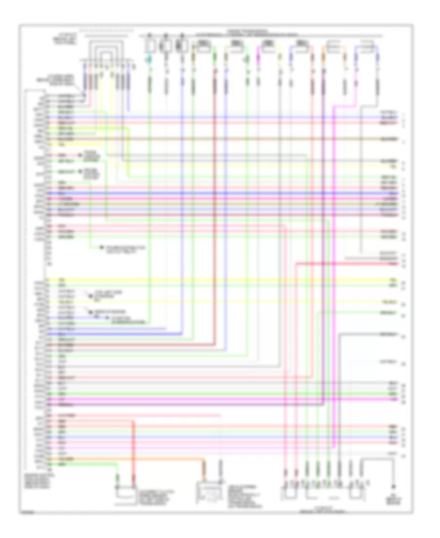
4.0L, Engine Performance Wiring Diagram (4 of 7) for Toyota Tundra 2005
 https://portal-diagnostov.com/license.html
Automotive Electricians Portal FZCO
Automotive Electricians Portal FZCO
https://portal-diagnostov.com/license.html
https://portal-diagnostov.com/license.html
Automotive Electricians Portal FZCO
Automotive Electricians Portal FZCOList of elements for 4.0L, Engine Performance Wiring Diagram (4 of 7) for Toyota Tundra 2005:
- (behind upper right side of dash) j/c 65
- (engine harn, at front of engine)
- (left side
- (right side
- E14 (engine harn, at rear of engine)
- E17
- Engine coolant temperature sensor (right rear of engine)
- Ev (left side of engine)
- From air fuel ratio sensor shields (diagram 2 of 7)
- From heated oxygen sensor shields (diagram 2 of 7)
- Nca
- Of engine) knock control sensor (bank 1)
- Of engine) knock control sensor (bank 2)
- Power steering oil pump switch (right front of engine)
- Red
- Vsv (acis) (top left of engine)
- Vsv (evap) (left side of engine)
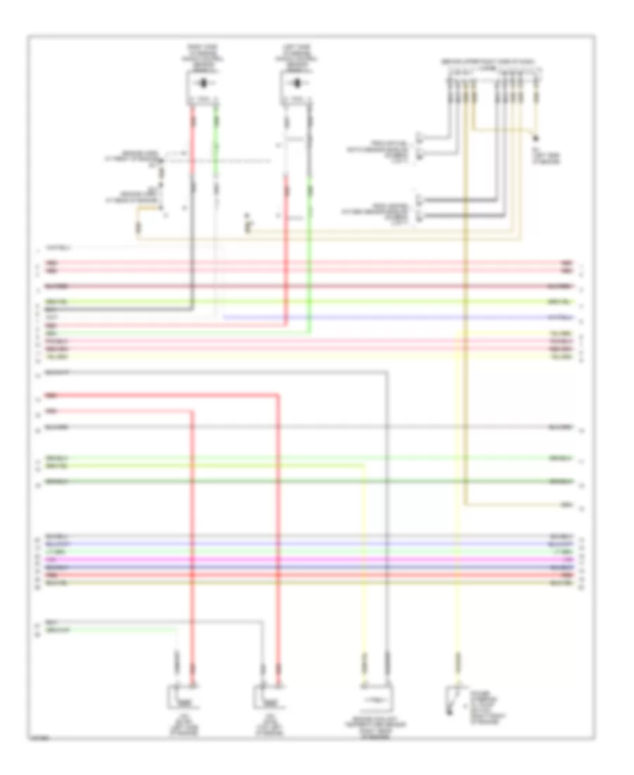
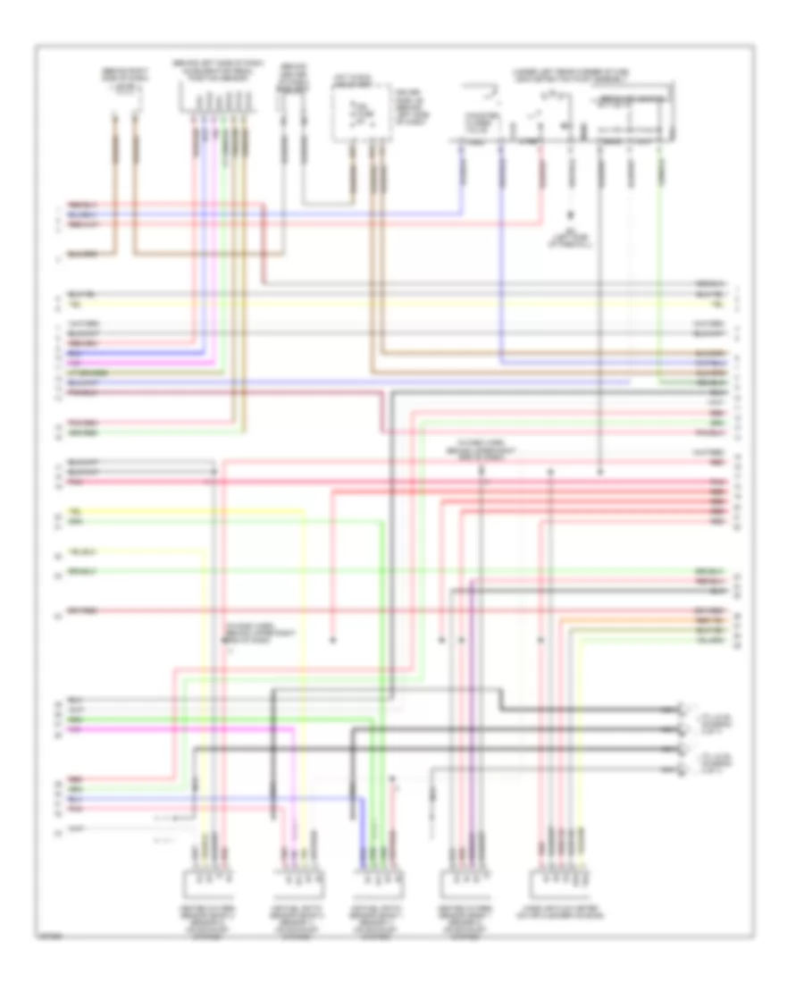
4.0L, Engine Performance Wiring Diagram (5 of 7) for Toyota Tundra 2005
 https://portal-diagnostov.com/license.html
Automotive Electricians Portal FZCO
Automotive Electricians Portal FZCO
https://portal-diagnostov.com/license.html
https://portal-diagnostov.com/license.html
Automotive Electricians Portal FZCO
Automotive Electricians Portal FZCOList of elements for 4.0L, Engine Performance Wiring Diagram (5 of 7) for Toyota Tundra 2005:
- (engine harn, at rear of engine) e14
- (upper left side of dash) diode (a/t)
- A red
- A/f htr fuse 20a
- Acc fuse 15a
- Driver side j/b (behind left side of dash)
- E14
- E15 (engine harn, right front of engine)
- Efi 1 fuse 15a
- Efi 2 fuse 15a
- Engine room r/b (left side of engine compt)
- Etcs fuse 10a
- Ev (left side of engine)
- G11
- Gauge fuse 10a
- Hot at all times
- Hot in run or acc
- Hot in run or start
- Igniter & ignition coil 1 (top of left cylinder bank)
- Igniter & ignition coil 2 (top of right cylinder bank)
- Igniter & ignition coil 3 (top of right cylinder bank)
- Igniter & ignition coil 4 (top of left cylinder bank)
- Igniter & ignition coil 5 (top of right cylinder bank)
- Igniter & ignition coil 6 (top of left cylinder bank)
- J/c 8 (behind upper left side of dash)
- J/c 9 (behind upper left side of dash)
- J26
- J26 j/c 26, 27 (behind left kick panel)
- J27
- Noise filter (top rear of engine)
- Red
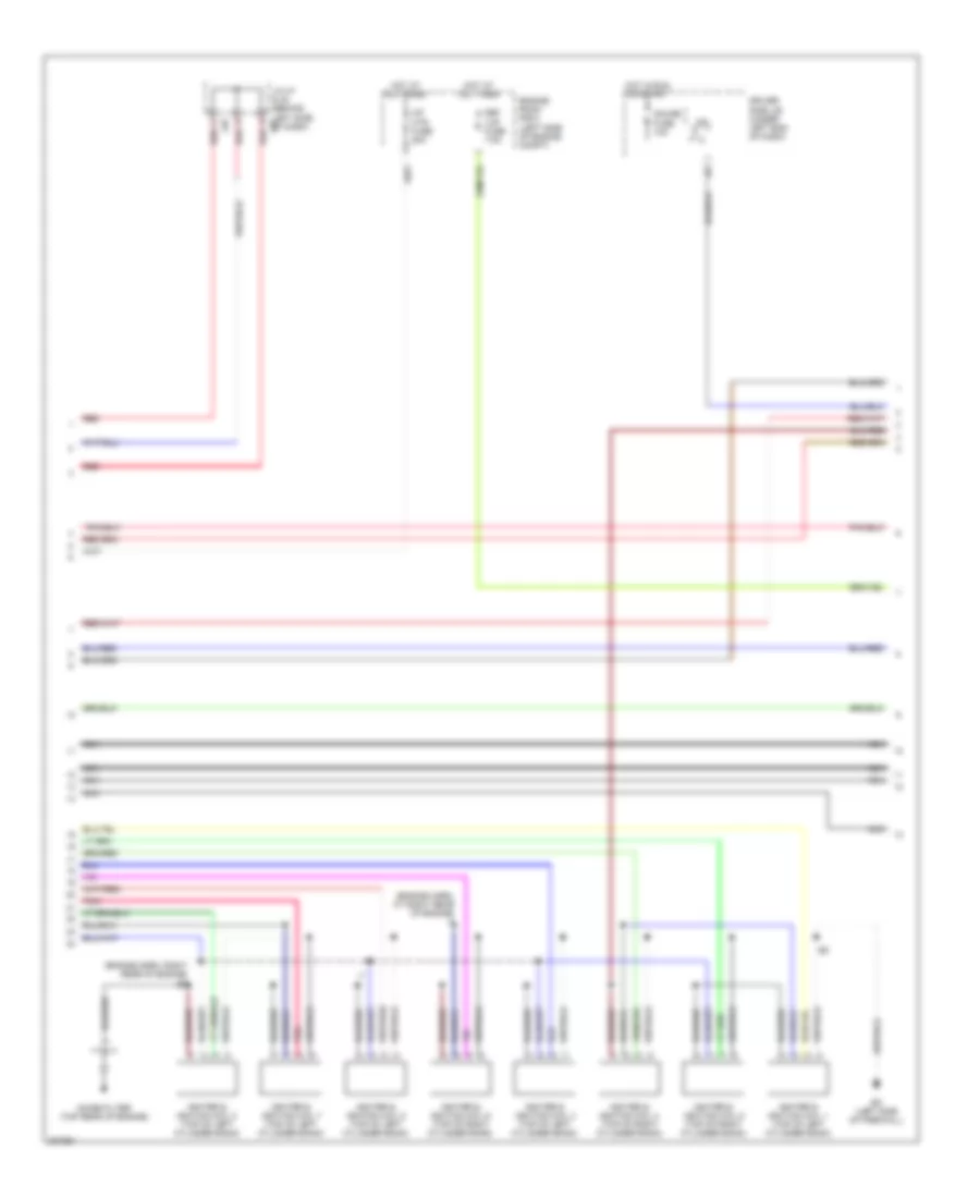
4.0L, Engine Performance Wiring Diagram (6 of 7) for Toyota Tundra 2005
 https://portal-diagnostov.com/license.html
Automotive Electricians Portal FZCO
Automotive Electricians Portal FZCO
https://portal-diagnostov.com/license.html
https://portal-diagnostov.com/license.html
Automotive Electricians Portal FZCO
Automotive Electricians Portal FZCOList of elements for 4.0L, Engine Performance Wiring Diagram (6 of 7) for Toyota Tundra 2005:
- A j28
- Acc
- B j28
- C j28
- C11
- C12
- Camshaft timing oil control valve (left) (top left of engine)
- Camshaft timing oil control valve (right) (top right of engine)
- Combination meter
- D j28
- Driver side j/b (behind left side of dash)
- F j28
- G j28
- Hot at all times
- Ignition switch
- Ih (behind right kick panel)
- J/c 28, 29 (behind center of dash)
- J/c 5 (behind upper left side of dash)
- J/c 66 (behind right kick panel)
- J29
- J66 j/c 66, & 67 (behind right kick panel) j67
- Lock
- Malf ind lamp
- Oil press cntrl
- Park/neutral position switch (on transmission)
- Run
- Start
- Temp cntrl
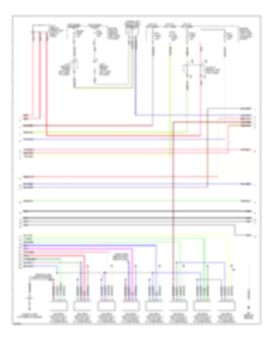
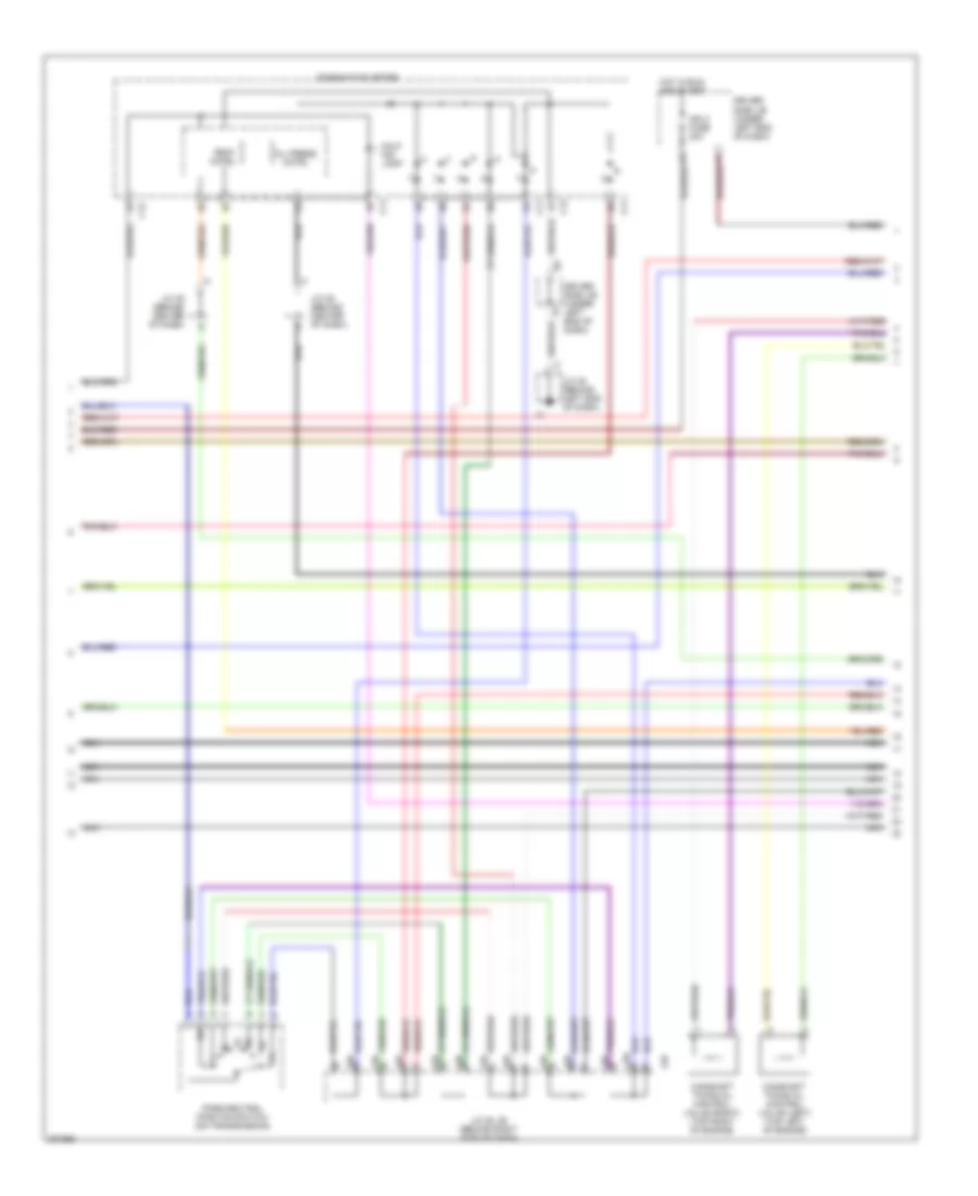
4.0L, Engine Performance Wiring Diagram (7 of 7) for Toyota Tundra 2005
 https://portal-diagnostov.com/license.html
Automotive Electricians Portal FZCO
Automotive Electricians Portal FZCO
https://portal-diagnostov.com/license.html
https://portal-diagnostov.com/license.html
Automotive Electricians Portal FZCO
Automotive Electricians Portal FZCOList of elements for 4.0L, Engine Performance Wiring Diagram (7 of 7) for Toyota Tundra 2005:
- (dash harn, behind right side of dash)
- 4wd
- 4wd circuit
- Ac1
- Act
- Canh
- Canl
- Crankshaft position sensor (left front of engine)
- Data link connector 3 (below left side of dash)
- Driver's side j/b (behind lower left side of dash)
- E18 (engine harn, right side of engine)
- Ec (rear of engine)
- Elsi
- Engine control module (ecm) (behind right side of dash)
- F/ps
- Frp
- Fuel injector
- Hot at all times
- Integration control & panel
- Integration relay
- J/c 66, & 67 (behind right kick panel)
- J/c 71 & 72 (behind upper left side of dash)
- J66
- J67
- J71
- J72
- Llp
- Lms
- Ne+
- Ne-
- Oc1+
- Oc1-
- Oc2+
- Oc2-
- Odlp
- Oilw
- Pnk
- Psw
- Red
- Spd
- Sta
- Starting/ charging system
- Stsw
- Tach
- Tail fuse 15a
- Thwo
- Transmissions system
- Vv1+
- Vv1-
- Vv2+
- Vv2-
- Vvt sensor (left) (top left side of engine)
- Vvt sensor (right) (top right side of engine)
4.7L
4.7L, Engine Performance Wiring Diagram, Access/Standard Cab (1 of 7) for Toyota Tundra 2005
 https://portal-diagnostov.com/license.html
Automotive Electricians Portal FZCO
Automotive Electricians Portal FZCO
https://portal-diagnostov.com/license.html
https://portal-diagnostov.com/license.html
Automotive Electricians Portal FZCO
Automotive Electricians Portal FZCOList of elements for 4.7L, Engine Performance Wiring Diagram, Access/Standard Cab (1 of 7) for Toyota Tundra 2005:
- (in dash harn, behind upper right side of dash)
- (inside transmission) electronically controlled transmission solenoid
- (rear of engine) ec
- (top left side of engine) ew
- +b2
- +bm
- A1a+
- A1a-
- A2a+
- A2a-
- Accr
- Aidi
- Airp
- Airv
- Batt
- Cruise control system
- E03
- E04
- E05
- Ec (rear of engine)
- Ekn2
- Eknk
- Engine control module (ecm) (behind right side of dash)
- Epa
- Epa2
- Ha1a
- Ha2a
- Ht2b
- Igsw
- J/c 26 & 27 (behind left kick panel)
- J26
- J27
- Knk1
- Knk2
- Me01
- Mpmp
- Mrel
- No 1
- No 2
- Nsw
- Nt+
- Nt-
- O/d direct clutch speed sensor (on left side of transmission)
- Odms
- Ox2b
- Pnk
- Power distribution (acc cut relay)
- Ppmp
- Red
- Sl1
- Sl1+
- Sl1-
- Sl2
- Sl2+
- Sl2-
- Slt
- Slt+
- Slt-
- Slu
- Slu+
- Slu-
- Sp2+
- Sp2-
- Starting/ charging system
- Stp
- Th02
- Tho1
- Trans- missions system
- Vcp2
- Vcpa
- Vehicle speed sensor (electronically controlled transmission) (on transmission)
- Vpa
- Vpa2
- Vpmp
4.7L, Engine Performance Wiring Diagram, Access/Standard Cab (2 of 7) for Toyota Tundra 2005
 https://portal-diagnostov.com/license.html
Automotive Electricians Portal FZCO
Automotive Electricians Portal FZCO
https://portal-diagnostov.com/license.html
https://portal-diagnostov.com/license.html
Automotive Electricians Portal FZCO
Automotive Electricians Portal FZCOList of elements for 4.7L, Engine Performance Wiring Diagram, Access/Standard Cab (2 of 7) for Toyota Tundra 2005:
- (behind left side of dash) accelerator pedal position sensor
- (behind right kick panel) j/c 66
- (in dash harn, behind right side of dash)
- (left side of engine compt) j/c 1
- (under left rear corner of cab) leak detection pump assembly
- Af+
- Af-
- Air fuel ratio sensor (bank 1 sensor 1) (on top left of engine)
- Air fuel ratio sensor (bank 2 sensor 1) (on exhaust system)
- Canister closed valve
- Driver side j/b (behind left side of dash)
- E2g
- Ec (rear of engine)
- Epa
- Epa2
- F10
- F11
- Heated oxygen sensor (bank 1 sensor 2) (on exhaust system)
- Heated oxygen sensor (bank 2 sensor 2) (on exhaust system)
- Hot in run and start
- Ign fuse 5a
- J26 j/c 26 & 27 (behind left kick panel)
- J27
- Mass air flow meter (on air cleaner housing)
- Mgnd
- Mtrb
- Nca
- Nca a
- Nca b
- Nca c
- Nca d
- Pnk
- Pressure sensor
- Red
- Sgnd
- Tha
- To j/c 64 (diagram 4 of 7)
- Vcc
- Vcp2
- Vcpa
- Vgnd
- Vlvb
- Vout
- Vpa
- Vpa2
4.7L, Engine Performance Wiring Diagram, Access/Standard Cab (3 of 7) for Toyota Tundra 2005
 https://portal-diagnostov.com/license.html
Automotive Electricians Portal FZCO
Automotive Electricians Portal FZCO
https://portal-diagnostov.com/license.html
https://portal-diagnostov.com/license.html
Automotive Electricians Portal FZCO
Automotive Electricians Portal FZCOList of elements for 4.7L, Engine Performance Wiring Diagram, Access/Standard Cab (3 of 7) for Toyota Tundra 2005:
- (dash harn, behind right side of dash)
- (engine harn, at right front of engine) e11
- (in fuel tank) fuel pump
- (left side of engine compt) fuel pump resistor
- A/f htr relay
- Acis
- Aip
- Air pressure sensor (top left of engine)
- Aiv1
- Aiv2
- C/opn relay
- E01
- E02
- E2g
- Ea (on left front fender)
- Ec (rear of engine)
- Efi relay
- Engine control module (ecm) (behind right side of dash)
- Engine room r/b (left side of engine compt)
- Et (right side of engine compt)
- Fuel pump relay
- Ge01
- Ht1b
- Igf1
- Igf2
- Igt1
- Igt2
- Igt3
- Igt4
- Igt5
- Igt6
- Igt7
- Igt8
- J/c 18
- J/c 26 & 27 (behind left kick panel)
- J/c 3 (behind left kick panel)
- J26
- J27
- Ox1b
- Pnk
- Prg
- Red
- Tha
- Throttle control motor & throttle position sensor (on throttle body assembly)
- Thw
- Vta
- Vta1
- Vta2
4.7L, Engine Performance Wiring Diagram, Access/Standard Cab (4 of 7) for Toyota Tundra 2005
 https://portal-diagnostov.com/license.html
Automotive Electricians Portal FZCO
Automotive Electricians Portal FZCO
https://portal-diagnostov.com/license.html
https://portal-diagnostov.com/license.html
Automotive Electricians Portal FZCO
Automotive Electricians Portal FZCOList of elements for 4.7L, Engine Performance Wiring Diagram, Access/Standard Cab (4 of 7) for Toyota Tundra 2005:
- (behind upper right side of dash) j/c 64
- (left side
- (right side
- A32
- A33
- Aipr fuse 60a
- Air injection control driver (left side of engine compt)
- Air pump (top left of engine)
- Air switching valve (top left of engine)
- Batt
- E13
- Engine coolant temperature sensor (right front of engine)
- Engine room r/b (left side of engine compt)
- Ew (top left side of engine)
- Ex (right rear of engine)
- From air fuel ratio sensor shields (diagram 2 of 7)
- From heated oxygen sensor shields (diagram 2 of 7)
- Hot at all times
- Nca
- Of engine) knock control sensor (bank 1)
- Of engine) knock control sensor (bank 2)
- Pnk
- Red
- Sip
- Siv
- Vsv (acis) (top left of engine)
- Vsv (air switching valve bank 1) (top center of engine)
- Vsv (air switching valve bank 2) (left rear of engine)
- Vsv (evap) (left side of engine)
4.7L, Engine Performance Wiring Diagram, Access/Standard Cab (5 of 7) for Toyota Tundra 2005
 https://portal-diagnostov.com/license.html
Automotive Electricians Portal FZCO
Automotive Electricians Portal FZCO
https://portal-diagnostov.com/license.html
https://portal-diagnostov.com/license.html
Automotive Electricians Portal FZCO
Automotive Electricians Portal FZCOList of elements for 4.7L, Engine Performance Wiring Diagram, Access/Standard Cab (5 of 7) for Toyota Tundra 2005:
- (dash harn, behind right side of dash) i3
- (engine harn, at rear of engine) e5
- (upper left side of dash) diode (a/t)
- A red
- A/f htr fuse 20a
- Acc fuse 15a
- Driver side j/b (behind left side of dash)
- Ec (rear of engine)
- Efi 1 fuse 15a
- Efi 2 fuse 15a
- Engine room r/b (left side of engine compt)
- Etcs fuse 10a
- G11
- Gauge fuse 10a
- Hot at all times
- Hot in run or acc
- Hot in run or start
- Igniter & ignition coil 1 (top of left cylinder bank)
- Igniter & ignition coil 2 (top of left cylinder bank)
- Igniter & ignition coil 3 (top of left cylinder bank)
- Igniter & ignition coil 4 (top of right cylinder bank)
- Igniter & ignition coil 5 (top of left cylinder bank)
- Igniter & ignition coil 6 (top of right cylinder bank)
- Igniter & ignition coil 7 (top of left cylinder bank)
- Igniter & ignition coil 8 (top of right cylinder bank)
- J/c 8 (behind upper left side of dash)
- J/c 9 (behind upper left side of dash)
- J26
- J26 j/c 26, 27 (behind left kick panel)
- J27
- Nca
- Noise filter (top rear of engine)
- Pnk
- Red
4.7L, Engine Performance Wiring Diagram, Access/Standard Cab (6 of 7) for Toyota Tundra 2005
 https://portal-diagnostov.com/license.html
Automotive Electricians Portal FZCO
Automotive Electricians Portal FZCO
https://portal-diagnostov.com/license.html
https://portal-diagnostov.com/license.html
Automotive Electricians Portal FZCO
Automotive Electricians Portal FZCOList of elements for 4.7L, Engine Performance Wiring Diagram, Access/Standard Cab (6 of 7) for Toyota Tundra 2005:
- A j28
- Acc
- B j28
- C j28
- C11
- C12
- Camshaft timing oil control valve (left) (top left of engine)
- Camshaft timing oil control valve (right) (top right of engine)
- Combination meter
- D j28
- Driver side j/b (behind left side of dash)
- F j28
- G j28
- Hot at all times
- Ignition switch
- Ih (behind right kick panel)
- J/c 28, 29 (behind center of dash)
- J/c 5 (behind upper left side of dash)
- J/c 66 (behind right kick panel)
- J29
- J66 j/c 66, & 67 (behind right kick panel) j67
- Lock
- Malf ind lamp
- Nca
- Oil press cntrl
- Park/neutral position switch (on transmission)
- Run
- Start
- Temp cntrl
4.7L, Engine Performance Wiring Diagram, Access/Standard Cab (7 of 7) for Toyota Tundra 2005
 https://portal-diagnostov.com/license.html
Automotive Electricians Portal FZCO
Automotive Electricians Portal FZCO
https://portal-diagnostov.com/license.html
https://portal-diagnostov.com/license.html
Automotive Electricians Portal FZCO
Automotive Electricians Portal FZCOList of elements for 4.7L, Engine Performance Wiring Diagram, Access/Standard Cab (7 of 7) for Toyota Tundra 2005:
- (engine harn, at rear of engine) e5
- 4wd
- 4wd circuit
- Ac1
- Act
- Camshaft position sensor (left front of engine)
- Canh
- Canl
- Crankshaft position sensor (left front of engine)
- Data link connector 3 (below left side of dash)
- Driver's side j/b (behind lower left side of dash)
- Ec (rear of engine)
- Elsi
- Engine control module (ecm) (behind right side of dash)
- Ev1+
- Ev1-
- F/ps
- Frp
- Fuel injector
- G2+
- G2-
- Hot at all times
- Integration control & panel
- Integration relay
- J/c 66, & 67 (behind right kick panel)
- J/c 71 & 72 (behind upper left side of dash)
- J66
- J67
- J71
- J72
- Llp
- Lms
- Nca
- Ne+
- Ne-
- Oc1+
- Oc1-
- Oc2+
- Oc2-
- Odlp
- Oilw
- Pnk
- Red
- Spd
- Sta
- Starting/ charging system
- Stsw
- Tach
- Tail fuse 15a
- Thwo
- Transmissions system
- Vv2+
- Vv2-
- Vvt sensor (left) (top left side of engine)
- Vvt sensor (right) (top right side of engine)
4.7L, Engine Performance Wiring Diagram, Double Cab (1 of 7) for Toyota Tundra 2005
 https://portal-diagnostov.com/license.html
Automotive Electricians Portal FZCO
Automotive Electricians Portal FZCO
https://portal-diagnostov.com/license.html
https://portal-diagnostov.com/license.html
Automotive Electricians Portal FZCO
Automotive Electricians Portal FZCOList of elements for 4.7L, Engine Performance Wiring Diagram, Double Cab (1 of 7) for Toyota Tundra 2005:
- (behind right side of dash) j/c 75
- (inside transmission) electronically controlled transmission solenoid
- (left side of firewall) ec
- (right rear of engine) ey
- +b2
- +bm
- A1a+
- A1a-
- A2a+
- A2a-
- Accr
- Aidi
- Airp
- Airv
- Batt
- Cruise control system
- E03
- E04
- E05
- Ekn2
- Eknk
- Engine control module (ecm) (behind right side of dash)
- Epa
- Epa2
- Ha1a
- Ha2a
- Ht2b
- Igsw
- Knk1
- Knk2
- Me01
- Mpmp
- Mrel
- No 1
- No 2
- Nsw
- Nt+
- Nt-
- O/d direct clutch speed sensor (on left side of transmission)
- Odms
- Ox2b
- Pnk
- Power distribution (acc cut relay)
- Ppmp
- Red
- Sl1
- Sl1+
- Sl1-
- Sl2
- Sl2+
- Sl2-
- Slt
- Slt+
- Slt-
- Slu
- Slu+
- Slu-
- Sp2+
- Sp2-
- Starting/ charging system
- Stp
- Th02
- Tho1
- Trans- missions system
- Vcp2
- Vcpa
- Vehicle speed sensor (electronically controlled transmission) (on transmission)
- Vpa
- Vpa2
- Vpmp
4.7L, Engine Performance Wiring Diagram, Double Cab (2 of 7) for Toyota Tundra 2005
 https://portal-diagnostov.com/license.html
Automotive Electricians Portal FZCO
Automotive Electricians Portal FZCO
https://portal-diagnostov.com/license.html
https://portal-diagnostov.com/license.html
Automotive Electricians Portal FZCO
Automotive Electricians Portal FZCOList of elements for 4.7L, Engine Performance Wiring Diagram, Double Cab (2 of 7) for Toyota Tundra 2005:
- (behind center of dash) sub j/b 3
- (behind left side of dash) accelerator pedal position sensor
- (behind right side of dash) j/c 75
- (in dash harn, behind upper right end of dash)
- (under left rear corner of cab) leak detection pump assembly
- Af+
- Af-
- Air fuel ratio sensor (bank 1 sensor 1) (on exhaust system)
- Air fuel ratio sensor (bank 2 sensor 1) (on exhaust system)
- Canister closed valve
- Driver side j/b (behind left side of dash)
- E17
- E2g
- Ec (left side of firewall)
- Epa
- Epa2
- H11
- Heated oxygen sensor (bank 1 sensor 2) (on exhaust system)
- Heated oxygen sensor (bank 2 sensor 2) (on exhaust system)
- Hot in run and start
- Ign fuse 5a
- Mass air flow meter (on air cleaner housing)
- Mgnd
- Mtrb
- Nca
- Nca a
- Nca b
- Nca c
- Nca d
- Pnk
- Pressure sensor
- Red
- Sgnd
- Tha
- To j/c 64 (diagram 4 of 7)
- Vcc
- Vcp2
- Vcpa
- Vgnd
- Vlvb
- Vout
- Vpa
- Vpa2
4.7L, Engine Performance Wiring Diagram, Double Cab (3 of 7) for Toyota Tundra 2005
 https://portal-diagnostov.com/license.html
Automotive Electricians Portal FZCO
Automotive Electricians Portal FZCO
https://portal-diagnostov.com/license.html
https://portal-diagnostov.com/license.html
Automotive Electricians Portal FZCO
Automotive Electricians Portal FZCOList of elements for 4.7L, Engine Performance Wiring Diagram, Double Cab (3 of 7) for Toyota Tundra 2005:
- (dash harn, behind upper right end of dash)
- (in fuel tank) fuel pump
- (left side of engine compt) fuel pump resistor
- Acis
- Aip
- Air pressure sensor (top left of engine)
- Aiv1
- Aiv2
- Bq (below left front seat)
- C/opn relay
- E01
- E02
- E2g
- Ea (on left front fender)
- Ec (left side of firewall)
- Efi 1 fuse 20a
- Efi 2 fuse 10a
- Efi relay
- Engine control module (ecm) (behind right side of dash)
- Engine room j/b (left side of engine compt)
- Etcs fuse 10a
- Fuel pump relay
- Ge01
- Hot at all times
- Ht1b
- Igf1
- Igf2
- Igt1
- Igt2
- Igt3
- Igt4
- Igt5
- Igt6
- Igt7
- Igt8
- J/c 34
- Ox1b
- Pnk
- Prg
- Red
- Tha
- Throttle control motor & throttle position sensor (on throttle body assembly)
- Thw
- Vta
- Vta1
- Vta2
4.7L, Engine Performance Wiring Diagram, Double Cab (4 of 7) for Toyota Tundra 2005
 https://portal-diagnostov.com/license.html
Automotive Electricians Portal FZCO
Automotive Electricians Portal FZCO
https://portal-diagnostov.com/license.html
https://portal-diagnostov.com/license.html
Automotive Electricians Portal FZCO
Automotive Electricians Portal FZCOList of elements for 4.7L, Engine Performance Wiring Diagram, Double Cab (4 of 7) for Toyota Tundra 2005:
- (behind upper right side of dash) j/c 64
- (left side
- (right side
- A/f htr relay
- A32
- A33
- Air injection control driver (left side of engine compt)
- Air pump (top left of engine)
- Air pump fuse 40a
- Air switching valve (top left of engine)
- Batt
- Ea (on left front fender)
- Ec (left side of firewall)
- Engine coolant temperature sensor (right front of engine)
- Engine room r/b 2 (left side of engine compt)
- Ey (left side of engine)
- Ez (right rear of engine)
- From air fuel ratio sensor shields (diagram 2 of 7)
- From heated oxygen sensor shields (diagram 2 of 7)
- Fusible link block (left side of engine compt)
- Hot at all times
- J/c 34
- Nca
- Of engine) knock control sensor (bank 1)
- Of engine) knock control sensor (bank 2)
- Pnk
- Red
- Sip
- Siv
- Vsv (acis) (top left of engine)
- Vsv (air switching valve bank 1) (top center of engine)
- Vsv (air switching valve bank 2) (left rear of engine)
- Vsv (evap) (left side of engine)
4.7L, Engine Performance Wiring Diagram, Double Cab (5 of 7) for Toyota Tundra 2005
 https://portal-diagnostov.com/license.html
Automotive Electricians Portal FZCO
Automotive Electricians Portal FZCO
https://portal-diagnostov.com/license.html
https://portal-diagnostov.com/license.html
Automotive Electricians Portal FZCO
Automotive Electricians Portal FZCOList of elements for 4.7L, Engine Performance Wiring Diagram, Double Cab (5 of 7) for Toyota Tundra 2005:
- (engine harn, at right rear of engine) i1
- (engine harn, right rear of engine) e2
- A red
- A/f htr fuse 20a
- C red
- Def i/up fuse 7.5a
- Driver side j/b (under left end of dash)
- Ec (left side of firewall)
- Engine room r/b 2 (left side of engine compt)
- Gauge fuse 10a
- Hot at all times
- Hot in run or start
- Igniter & ignition coil 1 (top of left cylinder bank)
- Igniter & ignition coil 2 (top of left cylinder bank)
- Igniter & ignition coil 3 (top of left cylinder bank)
- Igniter & ignition coil 4 (top of right cylinder bank)
- Igniter & ignition coil 5 (top of left cylinder bank)
- Igniter & ignition coil 6 (top of right cylinder bank)
- Igniter & ignition coil 7 (top of left cylinder bank)
- Igniter & ignition coil 8 (top of right cylinder bank)
- Ipo
- J/c 47 & 48 (behind left side of dash) j47
- J48
- Nca
- Noise filter (top rear of engine)
- Pnk
- Red
4.7L, Engine Performance Wiring Diagram, Double Cab (6 of 7) for Toyota Tundra 2005
 https://portal-diagnostov.com/license.html
Automotive Electricians Portal FZCO
Automotive Electricians Portal FZCO
https://portal-diagnostov.com/license.html
https://portal-diagnostov.com/license.html
Automotive Electricians Portal FZCO
Automotive Electricians Portal FZCOList of elements for 4.7L, Engine Performance Wiring Diagram, Double Cab (6 of 7) for Toyota Tundra 2005:
- A j28
- B j28
- C j28
- C11
- C12
- Camshaft timing oil control valve (left) (top left of engine)
- Camshaft timing oil control valve (right) (top right of engine)
- Combination meter
- D j28
- Driver side j/b (under left end of dash)
- F j28
- G j28
- Hot in run and start
- Ign 2 fuse 20a
- J/c 28, 29 (behind right side of dash)
- J/c 45 (behind left end of dash)
- J/c 49 (behind center of dash)
- J29
- Malf ind lamp
- Nca
- Oil press cntrl
- Park/neutral position switch (on transmission)
- Temp cntrl
4.7L, Engine Performance Wiring Diagram, Double Cab (7 of 7) for Toyota Tundra 2005
 https://portal-diagnostov.com/license.html
Automotive Electricians Portal FZCO
Automotive Electricians Portal FZCO
https://portal-diagnostov.com/license.html
https://portal-diagnostov.com/license.html
Automotive Electricians Portal FZCO
Automotive Electricians Portal FZCOList of elements for 4.7L, Engine Performance Wiring Diagram, Double Cab (7 of 7) for Toyota Tundra 2005:
- (behind center of dash) sub j/b 3
- (engine harn, right rear of engine) e2
- 4wd
- 4wd circuit
- Ac1
- Act
- Camshaft position sensor (left front of engine)
- Canh
- Canl
- Crankshaft position sensor (left front of engine)
- Data link connector 3 (below left side of dash)
- Driver side j/b (under left end of dash)
- E18
- Ec (left side of firewall)
- Els2
- Elsi
- Engine control module (ecm) (behind right side of dash)
- Ev1+
- Ev1-
- F/ps
- Frp
- Fuel injector
- G2+
- G2-
- Hot at all times
- Integration control & panel
- J/c 45 (behind left end of dash)
- J/c 49 (behind center of dash)
- J/c 76 & 77 (behind right side of dash)
- J76
- J77
- Llp
- Lms
- Nca
- Ne+
- Ne-
- Oc1+
- Oc1-
- Oc2+
- Oc2-
- Odlp
- Oilw
- Pnk
- Red
- Spd
- Sta
- Starting/ charging system
- Stsw
- Sub j/b 3 (behind center of dash)
- Tach
- Tail fuse 15a
- Thwo
- Transmissions system
- Vv2+
- Vv2-
- Vvt sensor (left) (top left side of engine)
- Vvt sensor (right) (top right side of engine)

 Čeština
 Dansk
Dansk Deutsch
 Ελληνικά
 English
 English
 Español
 Suomi
Suomi Français
 Français
 עברית
עברית Hrvatski
 Magyar
 Italiano
 한국어
한국어 Nederlands
 Polski
 Português
 Português
 Română
 Русский
 Slovenčina
 Slovenščina
 Svenska
 Türkçe
 中文 (中国)
