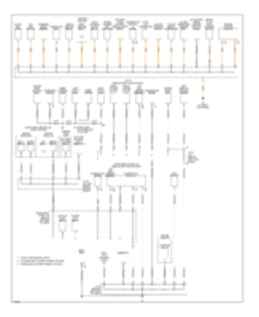
GROUND DISTRIBUTION
Ground Distribution Wiring Diagram (1 of 3) for Toyota Sequoia SR5 2003
 https://portal-diagnostov.com/license.html
Automotive Electricians Portal FZCO
Automotive Electricians Portal FZCO
https://portal-diagnostov.com/license.html
https://portal-diagnostov.com/license.html
Automotive Electricians Portal FZCO
Automotive Electricians Portal FZCO
List of elements for Ground Distribution Wiring Diagram (1 of 3) for Toyota Sequoia SR5 2003:
- 4wd control ecu
- A/c condenser fan motor
- A/c magnetic clutch & lock sensor
- A/c single pressure switch
- Add actuator
- Blower motor control
- Combination switch
- Data link connector
- E2 (engine harn, center of engine)
- Eb (right rear of engine)
- Ec (left side of engine)
- Engine control module
- Engine hood courtesy switch
- Engine room r/b 2
- Front wiper motor
- Heated oxygen sensor (bank 1, sensor 1)
- Heated oxygen sensor (bank 1, sensor 2)
- Heated oxygen sensor (bank 2, sensor 1)
- Heated oxygen sensor (bank 2, sensor 2)
- Heater relay
- I4 (i/p harn, behind right side of dash)
- Ignition coil & igniter 1
- Ignition coil & igniter 2
- Ignition coil & igniter 3
- Ignition coil & igniter 4
- Ignition coil & igniter 5
- Ignition coil & igniter 6
- Ignition coil & igniter 7
- Ignition coil & igniter 8
- J/c 1 (on right front of engine compt)
- J/c 18 (behind right end of dash)
- J/c 5 (on left side of engine compt)
- Left front foglight
- Left front turn signal & parking light 1
- Left front turn signal & parking light 2
- Noise filter 1
- Right front foglight
- Right front turn signal & parking light 1
- Right front turn signal & parking light 2
- Right remote control mirror
- Rr heater relay
- Skid control ecu w/ actuator
- To j/c 8 (diagram 2 of 3)
- Transfer neutral detection switch
- Transfer position detection switch 1
- Transfer position detection switch 2
- Transfer position detection switch l4
- Transfer shift actuator
- Washer level sensor
- Wireless door lock control buzzer
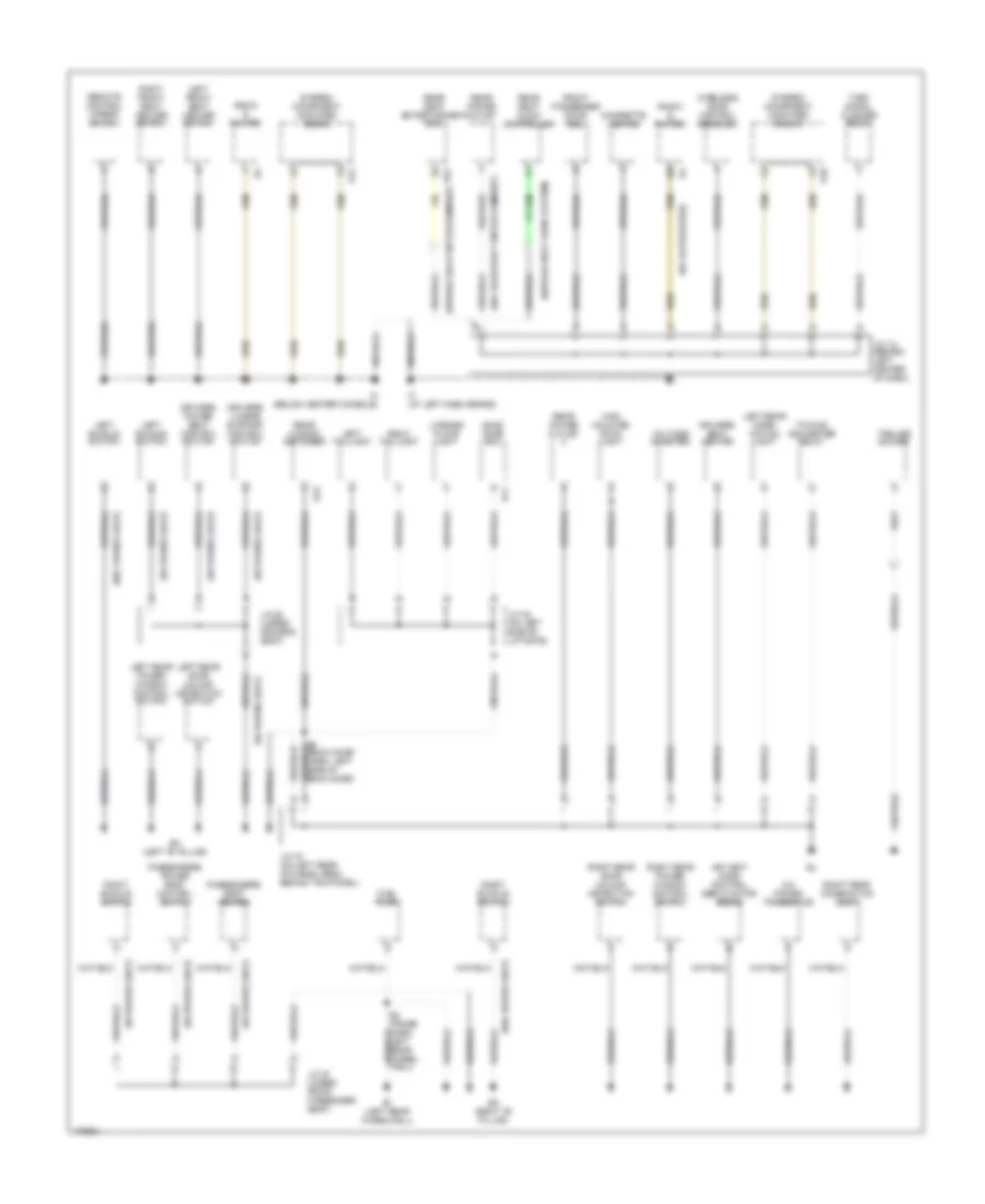
Ground Distribution Wiring Diagram (2 of 3) for Toyota Sequoia SR5 2003
 https://portal-diagnostov.com/license.html
Automotive Electricians Portal FZCO
Automotive Electricians Portal FZCO
https://portal-diagnostov.com/license.html
https://portal-diagnostov.com/license.html
Automotive Electricians Portal FZCO
Automotive Electricians Portal FZCOList of elements for Ground Distribution Wiring Diagram (2 of 3) for Toyota Sequoia SR5 2003:
- (roof harn, center front of roof)
- A/c control (rear heater control panel)
- A20
- Air bag sensor assembly
- Air vent mode control servo motor (front)
- Auto antenna motor relay
- B1 (roof harn, on upper left "a" pillar)
- Back-up light relay
- Battery charge relay
- Body ecu
- Brake fluid level warning switch
- C10
- Combination meter
- Combination switch
- Data link connector
- Daytime running light resistor
- Defog relay
- Driver door ecu
- Driver side r/b
- Drl 4 relay
- Efi relay
- Engine control module
- Engine room j/b
- Engine room r/b 2
- F10
- From j/c 18 (diagram 1 of 3)
- Front power outlet
- Glass breakage sensor ecu
- Glove box light
- I19
- Ig (at right kick panel)
- Inner mirror
- Instrument panel j/b (behind left end of dash)
- Integration control & panel
- Inverter relay
- J/c 28 (on left side of engine compt)
- J/c 43 (behind right side of dash)
- J/c 6, j/c 7 (behind left kick panel) j6
- J/c 8 (behind left end of dash)
- K12
- Left remote control mirror
- Left vanity light
- Main switch
- O/d main switch
- Overhead module
- Power main relay
- Rear interior light
- Rheostat
- Right vanity light
- Seat heater relay
- Sliding roof control ecu
- Start relay
- Steering angle sensor
- Towing brake controller
- Trans- ponder key computer
- Translate ecu
- Unlock warning switch
- W/daytime running lights
- W/o rear seat entertainment system
- W/rear seat entertainment system
Ground Distribution Wiring Diagram (3 of 3) for Toyota Sequoia SR5 2003
 https://portal-diagnostov.com/license.html
Automotive Electricians Portal FZCO
Automotive Electricians Portal FZCO
https://portal-diagnostov.com/license.html
https://portal-diagnostov.com/license.html
Automotive Electricians Portal FZCO
Automotive Electricians Portal FZCOList of elements for Ground Distribution Wiring Diagram (3 of 3) for Toyota Sequoia SR5 2003:
- (w/ 10 speakers)
- (w/ power seat)
- (w/o power seat)
- (w/o rear seat entertainment)
- (w/rear seat audio system)
- (w/rear seat entertainment)
- A/c power transistor
- Air vent mode control servo motor (rear)
- B11
- Back door ecu
- Bh (left "b" pillar)
- Bi (left rear wheelwell)
- Bk (right "b" pillar)
- Cigarette lighter
- Driver's lumbar support control switch
- Driver's power seat control switch
- Driver's seat heater
- Front passenger door ecu
- Fuel pump
- High mounted stop- light
- If (at left dash brace)
- Im (below center console)
- J/c 12 (behind left center of dash)
- J/c 19 (on left rear of cargo area, behind trim panel)
- J/c 22 (on left side of liftgate)
- J/c 25 (under driver's seat)
- J/c 27 (under front passenger seat)
- Left buckle switch
- Left front seat heater switch
- Left rear combi- nation light
- Left rear door unlock detection switch
- Left rear power window control switch
- Left taillight
- License plate light
- Passenger's power seat control switch
- Passenger's seat heater
- R15
- R22
- Radio & player
- Rear power outlet
- Rear seat audio controller
- Rear seat entertainment ecu
- Rear window defogger
- Remote control mirror switch
- Right buckle switch
- Right front seat heater switch
- Right rear combination light
- Right rear door unlock detection switch
- Right rear power window control switch
- Right taillight
- S10
- S12
- Stereo component amplifier (front)
- Stereo component amplifier (rear)
- Towing converter relay
- Trailer socket
- Turn signal flasher relay
- Voltage inverter
- Wireless door control receiver

 Čeština
 Dansk
Dansk Deutsch
 Ελληνικά
 English
 English
 Español
 Suomi
Suomi Français
 Français
 עברית
עברית Hrvatski
 Magyar
 Italiano
 한국어
한국어 Nederlands
 Polski
 Português
 Português
 Română
 Русский
 Slovenčina
 Slovenščina
 Svenska
 Türkçe
 中文 (中国)
