POWER DISTRIBUTION
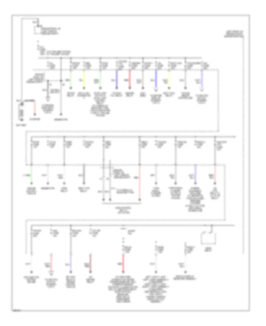
Power Distribution Wiring Diagram (1 of 3) for Toyota Tacoma X-Runner 2013
 https://portal-diagnostov.com/license.html
Automotive Electricians Portal FZCO
Automotive Electricians Portal FZCO
https://portal-diagnostov.com/license.html
https://portal-diagnostov.com/license.html
Automotive Electricians Portal FZCO
Automotive Electricians Portal FZCO
List of elements for Power Distribution Wiring Diagram (1 of 3) for Toyota Tacoma X-Runner 2013:
- (left front of engine compt) engine room r/b
- (not used)
- (w/o trailer towing) (w/ trailer towing)
- A/c amplifier, combination meter, transponder key ecu, steering sensor occupant classification ecu (w/ separate seat), door control receiver, body ecu & inner rear view mirror
- A/f heater relay
- A/f htr fuse 15a
- A/f htr relay & ai valve relay
- A/pump fuse 50a
- Abs 1 fuse 50a
- Abs 2 fuse 30a
- Air injection control driver
- Air pump htr fuse 10a
- Alt fuse 120a 140a
- Alt-s fuse 7.5a
- Am1 fuse 50a
- Am2 fuse 30a
- Batt chg fuse 30a
- Batt chg relay
- Battery
- Data link connector
- Dome fuse 7.5a
- Ecu-b fuse 7.5a
- Efi main fuse 20a
- Efi main relay & engine control module
- Engine control module
- Engine room j/b (left side of engine compt)
- Etcs fuse 10a
- Fr fog fuse 15a
- Fr fog relay
- Generator
- Head relay
- Heater fuse 50a
- Heater relay
- Horn fuse 10a
- Horn relay
- Inv fuse 100a
- J/b fuse 50a
- Left vanity light (left visor assembly) (if equipped) right vanity light (right visor assembly) (if equipped) center room lamp, map lamp & hazard warning signal switch assembly
- Obd fuse 7.5a
- Radio & display receiver assembly
- Radio 1 fuse 20a
- Radio 2 fuse 30a
- Red
- S/htr 1 fuse 50a
- S/htr 2 fuse 30a
- Seat htr relay
- Short pin
- Skid control ecu w/ actuator
- Starter
- Stereo component amplifier (w/ separate type amplifier) speaker (woofer) (w/ built-in type amplifier & access cab)
- Stop fuse 10a
- Stop lamp switch & stop lamp control relay (w/ hydraulic booster type, vacuum booster type w/ trailer towing)
- To driver side j/b (diagram 3 of 3)
- To engine room r/b 2 (diagram 3 of 3)
- To ignition switch (diagram 2 of 3)
- Towing brake controller
- Towing brk fuse 30a
- Towing fuse 30a
- Towing tail fuse 30a
- Towing tail relay
- Trn-haz fuse 15a
- Turn signal flasher (w/ drl & trailer towing)
- Turn signal flasher (w/ drl)
- W/ hydraulic booster type
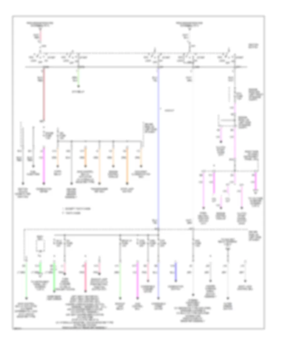
Power Distribution Wiring Diagram (2 of 3) for Toyota Tacoma X-Runner 2013
 https://portal-diagnostov.com/license.html
Automotive Electricians Portal FZCO
Automotive Electricians Portal FZCO
https://portal-diagnostov.com/license.html
https://portal-diagnostov.com/license.html
Automotive Electricians Portal FZCO
Automotive Electricians Portal FZCOList of elements for Power Distribution Wiring Diagram (2 of 3) for Toyota Tacoma X-Runner 2013:
- (2.7l)
- (right side of dash) instrument panel j/b 2
- 2.7l a/t
- 4.0l a/t
- 4wd control ecu
- 4wd fuse 20a
- 4wd m/t
- A/t
- A11
- Acc
- Acc fuse 7.5a
- Am1
- Am2
- B10
- B11
- B18
- Backup lamp relay
- Backup lamp switch (m/t) & park/neutral position switch (a/t)
- Bkup lp fuse 10a
- Body ecu
- C/opn relay
- C13
- C14
- C17
- Center air bag sensor assembly
- Clutch start cancel switch (4wd)
- Clutch start diode (m/t)
- Combination meter
- Combination switch
- Driver side j/b (left side of dash)
- Engine control module
- Engine room j/b (left side of engine compt)
- Engine room r/b (left front of engine compt)
- Except tmmtx made
- From engine room r/b (diagram 1 of 3)
- Fuel injectors
- Gauge fuse 7.5a
- H11
- H13
- H15
- H17
- H20
- Hazard warning signal switch assembly
- I13
- I15
- Ig1
- Ig1 2 fuse 10a
- Ig1 fuse 10a
- Ig2
- Ign fuse 15a
- Ignition coils & noise filter (ignition)
- Ignition switch
- Inner rear view mirror
- J10
- J16
- J20
- Left seat heater sw, right seat heater sw, shift lock control ecu, hazard warning signal switch assembly, generator, air mix damper servo motor, a/c control assembly, air vent damper servo motor, a/c amplifier, stop lp ctrl relay & (w/ hydraulic booster, vacuum booster type & trailer towing) radio & display receiver assembly
- Lock
- M/t
- Occupant classification ecu
- Off
- Outer mirror switch
- Park/ neutral position switch (a/t)
- Pnk
- Shift lock control ecu
- Skid control ecu w/ actuator (w/ hydraulic booster type)
- Skid control ecu w/ actuator (w/o rear differential lock & w/ vacuum booster type)
- St1
- St2
- Sta fuse 7.5a
- Sta relay
- Start
- Stereo component amplifier (w/ separate type amplifier), speaker (woofer) & (w/ built-in type amplifier access cab) radio & display receiver assembly
- Stop lamp switch
- Tmmtx made
- To acc skt relay (diagram 3 of 3)
- To instrument panel j/b 1 (diagram 3 of 3)
- To voltage inverter (diagram 3 of 3)
- Transponder key ecu
- Turn signal flasher (w/ drl & trailer towing)
- Windshield washer motor
- Windshield wiper motor
- Wip fuse 30a
- Wsh fuse 10a
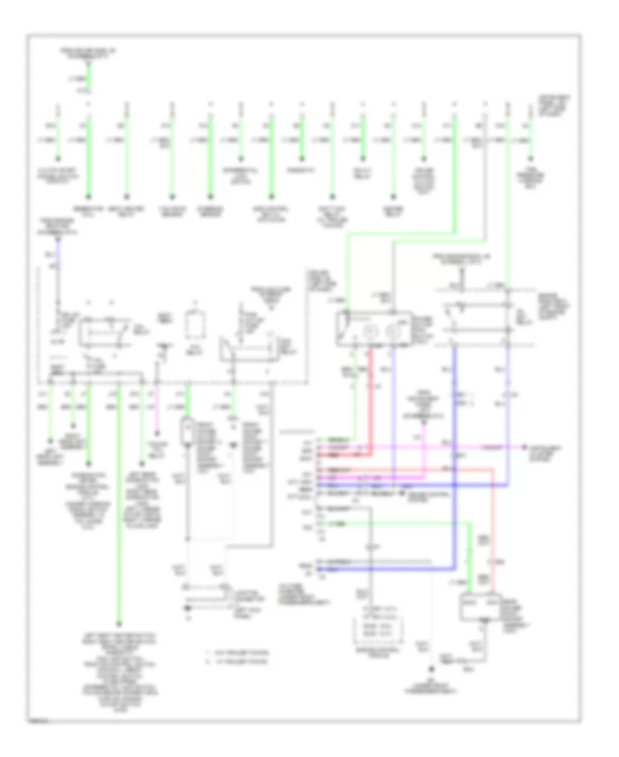
Power Distribution Wiring Diagram (3 of 3) for Toyota Tacoma X-Runner 2013
 https://portal-diagnostov.com/license.html
Automotive Electricians Portal FZCO
Automotive Electricians Portal FZCO
https://portal-diagnostov.com/license.html
https://portal-diagnostov.com/license.html
Automotive Electricians Portal FZCO
Automotive Electricians Portal FZCOList of elements for Power Distribution Wiring Diagram (3 of 3) for Toyota Tacoma X-Runner 2013:
- (2.7l)
- (4.0l)
- (a/t)
- (m/t)
- 400w
- A11
- A12
- A13
- Ac skt relay
- Ac1
- Ac2
- Acc skt relay
- Acc1
- Acc2
- Altb
- B15
- Batt chg relay (w/ trailer towing)
- Bc (under front passenger's seat)
- Bc1
- Bc2
- Body ecu
- C11
- C13
- C14
- Cccl
- Clutch start cancel switch (4wd m/t)
- Combination meter, engine control module, (2.7l) hazard warning signal switch assembly & tail diode (4.0l)
- Cruise control clutch switch (m/t)
- Cruise control system
- D10
- Differential lock switch
- Dr lck fuse 20a
- Driver side j/b (left side of dash)
- E13
- E21
- Ed1
- Ed2
- Els2
- Els3
- Engine control module
- Engine room r/b 2 (left front of engine compt)
- From acc fuse (diagram 2 of 3)
- From driver side j/b (diagram 2 of 3)
- From engine room j/b (diagram 1 of 3)
- From engine room r/b (diagram 1 of 3)
- From instrument panel j/b 2 (diagram 2 of 3)
- Front power outlet socket 2 power point socket assembly (12v)
- Front power point socket 1 power point socket assembly (12v)
- Generator (4.0l)
- Gnd
- H18
- Heater relay
- Ia4
- Im1
- Ind
- Instrument cluster system
- Instrument panel j/b 1 (left side of dash)
- J19
- Junction connector j1 (left kick panel)
- K11
- Left headlight assembly
- Left rear combination lamp, right rear combination lamp, left license plate lamp & right license plate lamp
- Left seat heater switch, right seat heater switch, spiral cable, rheostat, fog lamp switch, traction control switch, downhill assist control switch, (if equipped) differential lock switch, towing brake connector & curtain air bag cutoff switch (4wd)
- Mg clt relay
- Nsw
- Out
- P/t
- P/w relay
- Pgnd
- Power ind+ outlet main switch (120v) ind-
- Pwr outlet fuse 15a
- Rear power point socket assembly (120v)
- Red
- Redr
- Rheostat
- Right headlight assembly
- Seat heater relay
- Skid control ecu w/ actuator
- Spd
- Steering sensor
- Tail fuse 10a
- Tail relay
- Tire pressure warning ecu
- Towing tail relay
- Trly
- Voltage inverter (under front passenger's seat)
- W/ trailer towing
- W/o trailer towing
- Yaw rate sensor

 Čeština
 Dansk
Dansk Deutsch
 Ελληνικά
 English
 English
 Español
 Suomi
Suomi Français
 Français
 עברית
עברית Hrvatski
 Magyar
 Italiano
 한국어
한국어 Nederlands
 Polski
 Português
 Português
 Română
 Русский
 Slovenčina
 Slovenščina
 Svenska
 Türkçe
 中文 (中国)
