
 Čeština
 Dansk
Dansk Deutsch
 Ελληνικά
 English
 English
 Español
 Suomi
Suomi Français
 Français
 עברית
עברית Hrvatski
 Magyar
 Italiano
 한국어
한국어 Nederlands
 Polski
 Português
 Português
 Română
 Русский
 Slovenčina
 Slovenščina
 Svenska
 Türkçe
 中文 (中国)

Isuzu Hombre S 1996 - 1996 ENGINE PERFORMANCE Self-Diagnostics - Hombre - 2.2L
Isuzu Hombre S 1996 - INTRODUCTION
NOTE: For self-diagnostics on Oasis, refer to Odyssey in Honda TESTS W/CODES article.
If no faults were found while performing steps in BASIC TESTING article, proceed with self-diagnostics. If no Diagnostic Trouble Codes (DTCs) are present after entering self-diagnostics, proceed to TESTS W/O CODES article for diagnosis by symptoms.
Isuzu Hombre S 1996 - SYSTEM DESCRIPTION
The PCM monitors engine operation. It also contains a self-diagnostic system which stores Diagnostic Trouble Codes (DTCs) and compares them to On-Board Diagnostics Generation II (OBD-II) standards. Federal law mandates this type of diagnostic system for all vehicles by 1996.
The goal of OBD-II regulation is to provide vehicle with an on-board diagnostic system which is capable of continuously monitoring the efficiency of emission control systems, and to improve diagnosis and repair when system failures occur.
The Federal Test Procedure (FTP) sets maximum allowable emission standards. A Malfunction Indicator Light (MIL) must illuminate if a system or component either fails or deteriorates to a point where the vehicles emissions could rise above 1 1/2 times FTP standards.
DTCs may only be retrieved using an On-Board Diagnostic (OBD-II) scan tester.
Isuzu Hombre S 1996 - TRIP DETECTION LOGIC
Generation II data streams are prioritized. When two messages attempt to establish communications on a data line at the same time, only the message with higher priority will continue. A new segment of the software called the Diagnostic Executive coordinates the protocol for recording and displaying diagnostic procedures.
After engine has reached normal operating temperature, Diagnostic Executive checks if On Board Diagnostic Tests have been completed since last ignition cycle. It checks if tests have passed during current ignition cycle. Checks if fault identified by diagnostic tests is currently active. It also checks if fault identified has been active during current ignition cycle and what operating conditions were present at the time of failure.
Each test is separated in to four types:
- Type A - Turns the MIL on the first time an emission related failure occurs. The MIL will FLASH at a rate of once per second to alert the operator of potentially damaging levels of misfire, such that could destroy the catalytic converter.
- Type B - Will only turn MIL on if an emission related condition occurs during two consecutive driving cycles. Conditions such as incorrect fuel trim will be stored in the Freez-Frame data until the fault is detected a second time. If the fault is not detected during three consecutive driving cycles, the MIL light will be turned off.
- Type C - This is a non-emission related type and will not activate the MIL. It will turn ON a Check Transmission service light, or other non MIL service reminder light.
- Type D - Is non-emission related, will not turn the MIL or service light, but will store DTCs of faults present.
Isuzu Hombre S 1996 - SELF-DIAGNOSTIC SYSTEM HARD FAILURES
Hard failures cause Malfunction Indicator Light (MIL) to glow and remain on until problem is repaired. If light comes on and remains on (light may flash) during vehicle operation, cause of malfunction must be determined using diagnostic (code) charts. See DIAGNOSTIC TROUBLE CODE DEFINITIONS. If a sensor fails, Powertrain Control Module (PCM) will use a substitute value in its calculations to continue engine operation. In this condition, commonly known as limp-in mode, vehicle runs but driveability will not be optimum.
Isuzu Hombre S 1996 - INTERMITTENT FAILURES
Intermittent failures may cause MIL to flicker or glow and go out after intermittent fault goes away. However, corresponding trouble code will be retained in PCM memory. If related fault does not reoccur within a certain time frame, related trouble code will be erased from PCM memory. Intermittent failures may be caused by a sensor, connector or wiring related problems. See INTERMITTENTS in TESTS W/O CODES article.
Isuzu Hombre S 1996 - FREEZE-FRAME DATA
According to the 1996 government regulations, engine operating conditions under witch the MIL is illuminated must be recorded. This record, called freeze frame data, is a snap shot of the driving conditions, that is recorded on the PCM freeze frame buffer and is constantly updated with the most current information.
Freeze frame data can only be overwritten with misfire or fuel trim malfunction data. The data can only be erased by clearing associated history DTCs.
Isuzu Hombre S 1996 - DATA LINK CONNECTOR LOCATION
Located at lower left side of instrument panel, behind a small cover.
Isuzu Hombre S 1996 - RETRIEVING CODES
NOTE: Codes can be retrieved using a scan tester. Trouble codes are referred to as DTCs.
- Code retrieval starts with diagnostic circuit check. See DIAGNOSTIC CIRCUIT CHECK. MIL will come on when ignition is on and engine is not running. When engine is started, MIL should go off. If light remains on while engine is running, a trouble code is present.
- If light does not come on with ignition on and engine off, inspect MIL circuit before continuing. If MIL fails to operate, see DIAGNOSTIC CIRCUIT CHECK.
- To retrieve codes, install scan tool. Select MIL dash lamp control and command the MIL OFF. Ensure MIL light is off and attempt to start engine. If vehicle does not start, go to vehicle NO-START tests.
Isuzu Hombre S 1996 - CLEARING CODES
- After repairs are performed, clear PCM memory of all stored codes. Ensure ignition is off. To clear codes, use diagnostic scan tool "clear DTCs" or "clear info" function. Follow instructions supplied by tool manufacturer, when clearing DTCs.
- Trouble codes can also be cleared by disconnecting any PCM power source or negative battery cable for at least 30 seconds. However, if disconnecting battery remember that other memory functions (clock, radio, etc.) will need to be reset.
Isuzu Hombre S 1996 - PCM REPROGRAM PROCEDURE
If PCM requires replacement PCM must be reprogrammed using a Tech I or other OBD II compatible scan tool.
Isuzu Hombre S 1996 - PCM LOCATION
PCM is located near left kick panel.
NOTE: If any DTCs not listed here are displayed by a scan tool, the scan tool data may be faulty. Notify the scan tool manufacturer of any DTCs displayed that are not included in the following table.
Isuzu Hombre S 1996 - DIAGNOSTIC TROUBLE CODE DEFINITIONS
Isuzu Hombre S 1996 DIAGNOSTIC TROUBLE CODE (DTC) IDENTIFICATION
DTC Type(1) Component/System Most Likely Cause P0106 A MAP Sensor Circuit Range/Performance Problem MAP Sensor P0107 A MAP Sensor Circuit Low Frequency Open/Short, MAP Sensor Or PCM P0108 A MAP Sensor Circuit High Frequency Open, MAP Sensor Or PCM P0112 A IAT Sensor Circuit Low Frequency Short, IAT Sensor Or PCM P0113 A IAT Sensor Circuit High Frequency Open, IAT Sensor Or PCM P0117 A ECT Sensor Circuit Low Frequency Short, ECT Sensor Or PCM P0118 A ECT Sensor Circuit High Frequency Open, ECT Sensor Or PCM P0121 A TP Sensor Circuit Range/Performance Problem TP Sensor Or PCM P0122 A TP Sensor Circuit Low Frequency Open/Short, TP Sensor Or PCM P0123 A TP Sensor Circuit High Frequency Open Circuit, TP Sensor Or PCM P0125 B ECT Sensor Circuit Excessive Warm-Up Time To Closed Loop Cooling System, ECT Or PCM P0131 A Bank 1 Primary HO2S Circuit Low Voltage . Short, HO2S Sensor, Fuel Supply Or PCM P0132 A Bank 1 Primary HO2S Circuit High Voltage Open, HO2S Sensor Or PCM P0133 B Bank 1 Primary HO2S Slow Response HO2S Sensor Or Exhaust System P0134 A Bank 1 Primary HO2S Insufficient Activity Poor Connections, HO2S Sensor Or PCM P0137 A Bank 1 Secondary HO2S Circuit Low Voltage Short, HO2S Or PCM P0138 A Bank 1 Secondary HO2S Circuit High Voltage Open, HO2S Or PCM P0140 A Bank 1 Secondary HO2S Ckt. Insufficient Activity Short In Circuit, HO2S Or PCM P0141 B Bank 1 Secondary HO2S Circuit Malfunction Open/Short In Heater Circuit Or PCM P0171 B Bank 1 System Too Lean Fuel Supply/Contamination, Primary HO2S, MAP, Leaking Exhaust Or Valve Clearance P0172 B Bank 1 System Too Rich Fuel Supply, Primary HO2S, MAP Sensor, Fuel Contamination Or Valve Clearance P0300 B Random Misfire Detected Ignition System, Fuel Supply, MAP Sensor, EGR System, IAC Valve Or Contaminated Fuel P0301 B Cylinder No. 1 Misfire Detected Miscellaneous P0302 B Cylinder No. 2 Misfire Detected Miscellaneous P0303 B Cylinder No. 3 Misfire Detected Miscellaneous P0304 B Cylinder No. 4 Misfire Detected Miscellaneous P0325 A Knock Sensor (KS) Circuit Malfunction PCM P0335 A Crankshaft Position (CKP) Sensor Circuit Malfunction CKP Sensor, Circuit Or PCM P0341 A CKP Circuit Performance Open/Short, CKP Sensor, Faulty Or P0342 ..... CKP Circuit Performance Missing CKP Magnet OR PCM P0401 A CKP Sensor Low Frequency CKP Sensor/Magnet Or PCM P0420 A Insufficient EGR Flow Detected EGR Valve Or Line P0440 A Bank 1 Catalyst System Efficiency Below Threshold Catalytic Converter Or Secondary HO2S P0442 A EVAP System Canister Purge Valve, Vent Solenoid Or Hoses P0446 A EVAP Small Leak Detected Vent Solenoid, Fuel Cap Or Lines P0460 A EVAP Canister Vent Blocked Vent Solenoid Or Canister P0502 D EVAP Fuel Level Sensor Circuit Miscellaneous P0506 A VSS Circuit Low Frequency Open/Short, VSS Or PCM P0507 B Idle Control System Low RPM IAC Valve Or PCM P0530 B Idle Control System High RPM IAC Valve Or PCM P0562 D A/C Refrigerant Pressure Sensor Circuit Open, A/C Refrigerant Pressure Sensor Or PCM P0563 D System Voltage Low Open Or PCM P0600 D System Voltage High PCM P0601 A Loss Of Serial Communication Link PCM P0602 A Powertrain Control module (PCM) Memory Check Sum Error PCM D PCM Not Programmed PCM P0700(2) D Automatic Transaxle Miscellaneous P0705(2) D Transmission Range Sensor Circuit Malfunction Miscellaneous P0706(2) D Transmission Range Sensor Rationality Miscellaneous P0712(2) D Transmission Fluid Temperature Low Voltage Miscellaneous P0713(2) D Transmission Fluid Temperature High Voltage Miscellaneous P0715(2) D Transmission Jerks Hard When Shifting (A/T) Open/Short In Mainshaft Speed Sensor Circuit P0715(2) D Transmission Jerks Hard When Shifting (A/T) Or Faulty Mainshaft Speed Sensor P0719(2) D Brake Switch Circuit Low Miscellaneous P0720(2) D Lock-up Clutch Does Not Engage (A/T) Open Or Short In Countershaft Speed Sensor Circuit P0720(2) D Lock-up Clutch Does Not Engage (A/T) Or Faulty Countershaft Speed Sensor P0722(2) A Output Speed Sensor Circuit No Signal Miscellaneous P0723(2) ..... Output speed Sensor Circuit Intermittent Signal Miscellaneous P0724(2) D Brake Switch Circuit High Miscellaneous P0730(2) C Wont Shift Between 1/2nd, 2/3rd, 2/4th. Stuck in 1st Or 4th gears (A/T) Faulty Shift Control System P0740(2) ..... Lock-up clutch does not engage/disengage unstable Idle Speed (A/T) Faulty Lock-up Control system P0742(2) A Torque Converter Clutch Circuit Stuck On Miscellaneous P0748(2) C Transmission Pressure Control Solenoid Electrical Circuit Fault Miscellaneous P0751(2) B Transmission Shift Solenoid "A" Performance Or Stuck Off (A/T Only) Miscellaneous P0753(2) A Transmission Shift Solenoid "A" - Electrical Circuit Fault Open/Short In Ckt. Or Faulty Solenoid P0756(2) B Transmission Shift Solenoid "B" Performance Stuck Off (A/T Only) Miscellaneous P0758(2) A Transmission Shift Solenoid "B" - Electrical Circuit Fault Open/Short In Circuit Or Faulty Solenoid P1133 B Bank 1 Primary HO2S Circuit Insufficient Switching Exhaust Leak, Short In Circuit, HO2S Or PCM P1171 A Fuel System Lean During Acceleration Fuel Pressure,Incorrect Fuel Or Hot Fuel P1380 A ABS DTC Detected Rough Road, Data Unusable PCM P1381 A CPS Intermittent Interruption CYP Sensor P1406 A Exhaust Gas Recirculation (EGR) Valve Pintle Position Circuit Open/Short, EGR Or PCM P1441 B EVAP System Flow During Non-Purge Short, PCM, EVAP Purge Solenoid Or EVAP Vacuum Switch P1705(2) ..... (3) Short In A/T Gear Position Switch Wire Or Faulty A/T Gear Position Switch P1706(2) ..... (4) Open A/T Gear Position Switch Circuit Or Faulty A/T Gear Position Switch P1753(2) ..... Lock-Up Clutch Does Not Engage Or Disengage. Unstable Idle (A/T) Open/Short In Lock-Up Control Solenoid P1753(2) ..... Lock-up Clutch Wont Engage/Disengage. Unstable Idle (A/T) Valve "A" Circuit Or Faulty Solenoid P1758(2) ..... Lock-up Clutch Does Not Engage (A/T) Open/Short In Lock-up Control Solenoid P1758(2) ..... Lock-up Clutch Does Not Engage (A/T) Valve "B" Circuit Or Faulty Solenoid P1860(2) A TCC PWM Solenoid Circuit Fault Miscellaneous P1870(2) A Transmission Component Slipping Miscellaneous
(1) See Trip Detection Logic for Type Definitions.
(2) See appropriate ELECTRONIC CONTROLS article in the AUTOMATIC TRANSMISSIONS section.
(3) Only Shifts In 2nd and 4th Gears. Lock-up Clutch Does Not Engage (A/T).
(4) Only Shifts In 2nd And 4th Gears. Lock-up Clutch Does Not Engage Or Engages and Disengages Alternately (A/T).
Isuzu Hombre S 1996 - CIRCUIT TESTING
NOTE: For self-diagnostics on Oasis, refer to Odyssey in Honda TESTS W/CODES article.
NOTE: If PCM requires replacement, PCM must be reprogrammed using a Tech I or other OBD II compatible scan tool. For PCM harness connector and terminal identifications, see appropriate PIN VOLTAGE CHARTS article.
Isuzu Hombre S 1996 - DTC P0106 - MAP SENSOR SYSTEM PERFORMANCE


Fig. 1: Isuzu Hombre S 1996 - Component Locations - MAP Sensor Circuit (Hombre)
Isuzu Hombre S 1996 - Circuit Description
Powertrain Control Module (PCM) supplies a 5-volt reference signal and a ground circuit to Manifold Absolute Pressure (MAP) sensor. As manifold pressure changes, MAP sensor signal voltage changes. MAP sensor signal voltage should be 1.0-1.5 volts at idle and 4.5-4.8 volts at Wide Open Throttle (WOT).
Conditions required to set DTC:
- Idle speed dose not vary more than 150 RPM.
- IAC dose not vary more than 10 counts.
- TP sensor dos not vary more than one percent.
- EGR is stable.
- DTC P0107 and/or P0108 are not present.
- MAP voltage change is greater than .33 volts (6.3 kPa).
Isuzu Hombre S 1996 - Diagnostic Procedures
- Perform On-Board Diagnostic (OBD) System Check. After performing OBD system check, go to next step.
- Start engine and allow it to idle. Using scan tool, observe MAP sensor voltage. MAP sensor voltage should be 1.0-1.5 volt. If MAP sensor voltage varies by more than .33 volt, go to next step. If MAP sensor voltage does not vary by more than .33 volt, go to step 4).
- Turn ignition on, with engine off. Disconnect MAP sensor connector. Using scan tool, observe MAP sensor voltage. If voltage is one volt or less, go to step 5). If voltage is more than one volt, go to step 6).
- Observing scan tool display, wiggle, pull and twist MAP sensor connector. MAP sensor voltage should be 1.0-1.5 volt. If MAP sensor voltage varies by more than .33 volt, go to step 3). If MAP sensor voltage does not vary by more than .33 volt, go to step 7).
- Disconnect and inspect PCM and MAP sensor connectors. If connectors are okay, go to step 9). If connector(s) are not okay, go to step 8).
- Disconnect and inspect PCM connector. If connector is okay, go to step 12). If connector is not okay, go to step 8).
- Ensure ignition is on, with engine off. Using scan tool, review FREEZE FRAME data and note parameters. Observing scan tool display, drive vehicle at a steady speed. If MAP sensor voltage varies by more than .33 volt, go to step 3). If MAP sensor voltage does not vary by more than .33 volt, go to DIAGNOSTIC AIDS.
- Repair connector pins and/or wiring as necessary. After repair is completed, go to step 13).
- Check for restricted or leaking MAP sensor vacuum hose. If vacuum hose is okay, go to next step. If vacuum hose is not okay, go to step 11).
- Replace MAP sensor. After repair is completed, go to step 13).
- Replace MAP sensor vacuum hose as necessary. After repair is completed, go to step 13).
- Replace PCM. Program replacement PCM using required equipment. After repair is completed, go to next step.
- Using scan tool, select CLEAR INFO or CLEAR DTCS function to clear DTCs. Start engine and allow it to idle. Ensure engine is at normal operating temperature. Drive vehicle at a steady speed. Select SPECIFIC DTC function then enter DTC P0106. If scan tool indicates TEST RAN AND PASSED, go to next step. If scan tool does not indicate TEST RAN AND PASSED, repeat step 2).
- If any other DTCs are set, diagnose DTCs as necessary. If no other DTCs are set, no problem is indicated at this time.
Isuzu Hombre S 1996 - Diagnostic Aids
Turn ignition on, with engine off. MAP sensor voltage signal should be 4.5-4.8 volts. Compare this reading with a known-good vehicle with same style MAP sensor. Voltage readings should be within .4 volt of each other.
Isuzu Hombre S 1996 - DTC P0107 - MAP SENSOR CIRCUIT LOW VOLTAGE
NOTE: For circuit reference, see Code P0106 schematic.
Isuzu Hombre S 1996 - Circuit Description
Powertrain Control Module (PCM) supplies a 5-volt reference signal and a ground circuit to Manifold Absolute Pressure (MAP) sensor. As manifold pressure changes, MAP sensor signal voltage changes. MAP sensor signal voltage should be 1.0-1.5 volts at idle and 4.5-4.8 volts at Wide Open Throttle (WOT).
Conditions required to set DTC:
- Engine speed less than 1200 RPM.
- Throttle Position (TP) sensor angle more than 16 percent.
- DTC P0122 or P0123 not set.
- MAP voltage is no more than 14kPa.
Isuzu Hombre S 1996 - Diagnostic Procedures
- Perform On-Board Diagnostic (OBD) System Check. After performing OBD system check, go to next step.
- Start and run engine at idle. Using scan tool, observe MAP sensor voltage. If voltage is less than .25 volt, go to next step. If voltage is .25 volt or greater, go to step 4).
- Turn ignition off. Disconnect MAP sensor connector. Connect a jumper wire between signal circuit and 5-volt reference circuit terminals at MAP sensor harness connector. Turn ignition on. Observe scan tool. If voltage is more than 4.7 volts, go to step 5). If voltage is 4.7 volts or less, go to step 6).
- Ensure ignition is on, with engine off. Using scan tool, review FREEZE FRAME data and note parameters. Start engine and operate vehicle within conditions required for setting this DTC, and as close to conditions recorded in FREEZE FRAME as possible. If MAP sensor voltage is less than .25 volt, go to step 3). If MAP sensor voltage is .25 volt or more, go to DIAGNOSTIC AIDS.
- Disconnect and inspect MAP sensor connector. If connector is okay, go to step 9). If connector is not okay, go to step 8).
- Turn ignition off. Disconnect jumper wire from MAP sensor connector. Connect a test light between positive battery terminal and signal circuit terminal at MAP sensor harness connector. Turn ignition on. Observe scan tool. If MAP sensor voltage is more than 4 volts, go to next step. If MAP sensor voltage is 4 volts or less, go to step 12).
- Check MAP sensor 5-volt reference circuit for an open or short to ground. If 5-volt reference circuit is okay, go to step 11). If 5-volt reference circuit is not okay, go to step 10).
- Repair connector pins and/or wiring as necessary. After repair is completed, go to step 14).
- Replace MAP sensor. After repair is completed, go to step 14).
- Repair 5-volt reference circuit as necessary. After repair is completed, go to step 14).
- Replace and program replacement PCM. PCM requires special equipment for programming procedures. After repair is completed, go to step 14).
- Check MAP sensor signal circuit for an open or short to ground. If sensor signal circuit is okay, go to step 11). If sensor signal circuit is not okay, go to next step.
- Repair MAP sensor signal circuit as necessary. After repair is completed, go to next step.
- Using scan tool, select CLEAR INFO or CLEAR DTCS function to clear DTCs. Start and warm engine to normal operating temperature. Operate vehicle within conditions required for setting this DTC. Select SPECIFIC DTC function then enter DTC P0107. If scan tool indicates TEST RAN AND PASSED, go to next step. If scan tool does not indicate TEST RAN AND PASSED, repeat step 2).
- If any other DTCs are set, diagnose DTCs as necessary. If no other DTCs are set, no problem is indicated at this time.
Isuzu Hombre S 1996 - Diagnostic Aids
Turn ignition on, with engine off. MAP sensor voltage signal should be 4.5-4.8 volts. Compare this reading with a known-good vehicle with same style MAP sensor. Voltage readings should be within .4 volt of each other. After repairs are completed, use scan tool and access FUEL TRIM RESET function. Reset long term fuel trim to 128.
Isuzu Hombre S 1996 - DTC P0108 - MAP SENSOR CIRCUIT HIGH VOLTAGE
NOTE: For circuit reference, see Code P0106 schematic.
Isuzu Hombre S 1996 - Circuit Description
Powertrain Control Module (PCM) supplies a 5-volt reference signal and a ground circuit to Manifold Absolute Pressure (MAP) sensor. As manifold pressure changes, MAP sensor signal voltage changes. MAP sensor signal voltage should be 1.0-1.5 volts at idle and 4.5-4.8 volts at Wide Open Throttle (WOT).
Conditions required to set DTC:
- Vehicle speed sensor less than one MPH.
- Throttle Position (TP) sensor angle less than 12 percent.
- DTC P0122 or P0123 not set.
- MAP voltage is 82 kPa or less.
Isuzu Hombre S 1996 - Diagnostic Procedures
- Perform On-Board Diagnostic (OBD) System Check. After performing OBD system check, go to next step.
- Start and run engine at idle. Using scan tool, observe MAP sensor voltage. If voltage is 4 volts or greater, go to next step. If voltage is less than 4 volts, go to step 4).
- Turn ignition off. Disconnect MAP sensor connector. Turn ignition on. Using scan tool, observe MAP sensor voltage. If voltage is one volt or less, go to step 5). If voltage is more than one volt, go to step 6).
- Ensure ignition is on, with engine off. Using scan tool, review FREEZE FRAME data and note parameters. Start engine and operate vehicle within conditions required for setting this DTC, and as close to conditions recorded in FREEZE FRAME as possible. If MAP sensor voltage is 4 volts or more, go to step 3). If MAP sensor voltage is less than 4 volts, go to DIAGNOSTIC AIDS.
- Check for continuity between ground and sensor ground circuit terminal at MAP sensor harness connector. If continuity exists, go to step 7). If continuity does not exist, go to step 9).
- Check MAP sensor signal circuit for a short to voltage or a short to MAP sensor 5-volt reference circuit. If sensor signal circuit is okay, go to step 11). If sensor signal circuit is not okay, go to step 10).
- Check for restricted or leaking MAP sensor vacuum hose. If vacuum hose is okay, go to step 12). If vacuum hose is not okay, go to next step.
- Replace MAP sensor vacuum hose. After repair is completed, go to step 13).
- Repair open in MAP sensor ground circuit. After repair is completed, go to step 13).
- Repair MAP sensor signal circuit as necessary. After repair is completed, go to step 13).
- See DIAGNOSTIC AIDS. If no faults have been found, replace PCM. Program replacement PCM using required equipment. After repair is completed, go to step 13).
- Replace MAP sensor. After repair is completed, go to step 13).
- Using scan tool, select CLEAR INFO or CLEAR DTCS function to clear DTCs. Start and warm engine to normal operating temperature. Operate vehicle within conditions required for setting this DTC. Select SPECIFIC DTC function then enter DTC P0108. If scan tool indicates TEST RAN AND PASSED, go to next step. If scan tool does not indicate TEST RAN AND PASSED, repeat step 2).
- If any other DTCs are set, diagnose DTCs as necessary. If no other DTCs are set, no problem is indicated at this time.
Isuzu Hombre S 1996 - Diagnostic Aids
Turn ignition on, with engine off. MAP sensor voltage signal should be 4.5-4.8 volts. Compare this reading with a known-good vehicle with same style MAP sensor. Voltage readings should be within .4 volt of each other. Check 5-volt reference for short to battery voltage. After repairs are completed, use scan tool and access FUEL TRIM RESET function. Reset long term fuel trim to 128.
Isuzu Hombre S 1996 - DTC P0112 - IAT SENSOR CIRCUIT LOW VOLTAGE
Fig. 2: Isuzu Hombre S 1996 - Component Locations - IAT Sensor Circuit (Hombre)

Isuzu Hombre S 1996 - Circuit Description
Powertrain Control Module (PCM) supplies a 5-volt reference signal and a ground circuit to Intake Air Temperature (IAT) sensor. When intake air is cold, sensor resistance is high and when intake air is warm, sensor resistance low. When PCM senses a signal voltage lower than the normal operating range of the sensor, DTC will set.
Conditions for setting this DTC are as follows:
- Engine run time is more than 6 minutes.
- Vehicle speed more than 15 MPH.
- IAT sensor signal voltage indicates air temperature is more than 262?F (128?C).
Isuzu Hombre S 1996 - Diagnostic Procedures
- Perform On-Board Diagnostic (OBD) System Check. After performing OBD system check, go to next step.
- Turn ignition on, with engine off. Using scan tool, observe IAT sensor value. If IAT sensor value is 262?F (128?C) or less, go to next step. If IAT sensor value is more than 262?F (128?C), go to step 4).
- Turn ignition on, with engine off. Using scan tool, review FREEZE FRAME data and note parameters. Turn ignition off for about 15 seconds. Start engine and operate vehicle within conditions required for setting this DTC, and as close to conditions recorded in FREEZE FRAME as possible. Note IAT sensor value displayed on scan tool. If IAT sensor value is more than 262?F (128?C), go to next step. If IAT value is 262?F (128?C) or less, no problem is indicated at this time. Go to DIAGNOSTIC AIDS.
- Disconnect IAT sensor connector. Note IAT sensor value displayed on scan tool. If IAT sensor value is less than -22?F (-30?C), go to next step. If IAT sensor value is -22?F (-30?C) or more, go to step 6).
- Replace IAT sensor. After repair is completed, go to step 9).
- Connect a test light between positive battery terminal and signal circuit terminal at IAT sensor connector. If test light is on, go to next step. If test light is off, go to step 8).
- Repair short to ground in IAT sensor signal circuit. After repair is completed, go to step 9).
- Replace PCM. Program replacement PCM using required equipment. After repair is completed, go to next step.
- Using scan tool, select CLEAR INFO or CLEAR DTCS function to clear DTCs. Start and warm engine to normal operating temperature. Operate vehicle within conditions required for setting this DTC. Select SPECIFIC DTC function then enter DTC P0112. If scan tool indicates TEST RAN AND PASSED, go to next step. If scan tool does not indicate TEST RAN AND PASSED, repeat step 2).
- If any other DTCs are set, diagnose DTCs as necessary. If no other DTCs are set, no problem is indicated at this time.
Isuzu Hombre S 1996 - Diagnostic Aids
An intermittent problem can be caused by misrouted harness, rubbed through wire insulation or broken wire inside insulation.
If other DTCs are set for components that share the same ground and/or 5-volt reference circuit, check for faulty connections or wiring. PCM 5-volt reference circuits are internally connected within PCM.
If engine is allowed to sit overnight, ECT and IAT sensor values should be within a few degrees of each other. If sensor temperatures are not within a few degrees of each other, test IAT sensor. See IAT TEMPERATURE-TO-RESISTANCE VALUES.
Isuzu Hombre S 1996 IAT SENSOR TEMPERATURE VS. RESISTANCE VALUES
?F ?C OHMS 212 100 177 176 80 332 140 60 667 113 45 1188 95 35 1802 77 25 2796 59 15 4450 41 5 7280 23 -5 12300 5 -15 21450 -22 -30 52700 -40 -40 100700
Isuzu Hombre S 1996 - DTC P0113 - IAT SENSOR CIRCUIT HIGH VOLTAGE
NOTE: For circuit reference, see Code P0112 schematic.
Isuzu Hombre S 1996 - Circuit Description
Powertrain Control Module (PCM) supplies a 5-volt reference signal and a ground circuit to Intake Air Temperature (IAT) sensor. When intake air is cold, sensor resistance is high and when intake air is warm, sensor resistance low. When PCM senses a signal voltage lower than the normal operating range of the sensor, DTC will set.
Conditions for setting this DTC are as follows:
- Engine run time is greater than 6 minutes.
- Vehicle speed greater than 15 MPH.
- IAT sensor signal voltage indicates air temperature is less than -40?F (-40?C).
Isuzu Hombre S 1996 - Diagnostic Procedures
- Perform On-Board Diagnostic (OBD) System Check. After performing OBD system check, go to next step.
- Turn ignition on, with engine off. Using scan tool, observe IAT sensor value. If IAT sensor value is less than -22?F (-30?C), go to step 4). If IAT sensor value is -22?F (-30?C) or more, go to next step.
- Turn ignition on, with engine off. Using scan tool, review FREEZE FRAME data and note parameters. Start engine and operate vehicle within conditions required for setting this DTC, and as close to conditions recorded in FREEZE FRAME as possible. Note IAT sensor value displayed on scan tool. If IAT sensor value is less than -22?F (-30?C), go to next step. If IAT value is -22?F (-30?C) or greater, see DIAGNOSTIC AIDS.
- Disconnect IAT sensor connector. Connect a jumper wire between signal circuit and sensor ground circuit terminals at IAT sensor harness connector. Note IAT sensor value displayed on scan tool. If IAT sensor value is greater than 266?F (130?C), go to step 6). If IAT sensor value is 266?F (130?C) or less, go to next step.
- Connect a jumper wire between ground and signal circuit terminal at IAT sensor harness connector. Note IAT sensor value displayed on scan tool. If IAT sensor value is 266?F (130?C) or less, go to step 8). If IAT sensor value is greater than 266?F (130?C), go to step 7).
- Disconnect and inspect IAT sensor connector. Repair connector as necessary. After repair is completed, go to step 12). If connector is okay, go to step 10).
- Check for an open IAT sensor ground circuit. Repair wiring as necessary. After repair is completed, go to step 12). If circuit is okay, go to step 9).
- Check for an open IAT sensor signal circuit. Repair wiring as necessary. After repair is completed, go to step 12). If circuit is okay, go to next step.
- Check for poor IAT sensor ground or a poor IAT sensor signal circuit terminal connection at PCM. Repair as necessary. After repair is completed, go to step 12). If circuits are okay, go to step 11).
- Replace IAT sensor. After repair is completed, go to step 12).
- Replace PCM. Program replacement PCM using required equipment. After replacement is completed, go to next step.
- Using scan tool, select CLEAR INFO or CLEAR DTCS function to clear DTCs. Start and warm engine to normal operating temperature. Operate vehicle within conditions required for setting this DTC. Select SPECIFIC DTC function then enter DTC P0113. If scan tool indicates TEST RAN AND PASSED, go to next step. If scan tool does not indicate TEST RAN AND PASSED, repeat step 2).
- If any other DTCs are set, diagnose DTCs as necessary. If no other DTCs are set, no problem is indicated at this time.
Isuzu Hombre S 1996 - Diagnostic Aids
An intermittent problem can be caused by misrouted harness, rubbed through wire insulation or broken wire inside insulation.
If other DTC(s) are set for components that share the same ground and/or 5-volt reference circuit, check for faulty connections or wiring. PCM 5-volt reference circuits are internally connected within PCM.
If engine is allowed to sit overnight, ECT and IAT sensor values should be within a few degrees of each other. If temperatures are not within a few degrees of each other, test IAT sensor. See IAT TEMPERATURE-TO-RESISTANCE VALUES.
Isuzu Hombre S 1996 - DTC P0117 - ECT SENSOR CIRCUIT LOW VOLTAGE
Fig. 3: Isuzu Hombre S 1996 - Component Locations - ECT Sensor Circuit (Hombre)

Isuzu Hombre S 1996 - Circuit Description
Powertrain Control Module (PCM) supplies a 5-volt reference signal and a ground circuit to Engine Coolant Temperature (ECT) sensor. With engine cold, sensor resistance is high and when engine is warm, sensor resistance is low. When PCM senses a signal voltage lower than the normal operating range of the sensor, DTC will set.
Conditions for setting this DTC are as follows:
- Engine run time is greater than 2 minutes.
- ECT sensor signal voltage indicates engine coolant temperature is greater than 280?F (138?C).
Isuzu Hombre S 1996 - Diagnostic Procedures
- Perform On-Board Diagnostic (OBD) System Check. After performing OBD system check, go to next step.
- Turn ignition on, with engine off. Using scan tool, observe ECT sensor value. If ECT sensor value is greater than 266?F (130?C), go to step 4). If ECT sensor value is 266?F (130?C) or less, go to next step.
- Turn ignition on, with engine off. Using scan tool, review FREEZE FRAME data and note parameters. Start engine and operate vehicle within conditions required for setting this DTC, and as close to conditions recorded in FREEZE FRAME as possible. Using scan tool, observe ECT sensor value. If ECT sensor value is greater than 266?F (130?C), go to next step. If ECT sensor value is 266?F (130?C) or less, see DIAGNOSTIC AIDS.
- Disconnect ECT sensor connector. Observe ECT sensor value. If ECT sensor value is less than -22?F (-30?C), go to step 6). If ECT sensor value is -22?F (-30?C) or greater, go to next step.
- Check for short to ground in ECT sensor signal circuit. Repair wiring as necessary. After repair is completed, go to step 8). If circuit is okay, go to step 7).
- Replace ECT sensor. After repair is completed, go to step 8).
- Replace PCM. Program replacement PCM using required equipment. After repair is completed, go to next step.
- Using scan tool, select CLEAR DTCs or CLEAR INFO function to clear DTCs. Start and warm engine to normal operating temperature. Operate vehicle within conditions required for setting this DTC. Select SPECIFIC DTC function then enter DTC P0117. If scan tool indicates TEST RAN AND PASSED, go to next step. If scan tool does not indicate TEST RAN AND PASSED, return to step 2).
- If any other DTCs are set, diagnose DTCs as necessary. If no other DTCs are set, no problem is indicated at this time.
Isuzu Hombre S 1996 - Diagnostic Aids
An intermittent problem can be caused by misrouted harness, rubbed through wire insulation or broken wire inside insulation.
If other DTC(s) are set for components that share the same ground and/or 5-volt reference circuit, check for faulty connections or wiring. PCM 5-volt reference circuits are internally connected within PCM.
If engine is allowed to sit overnight, ECT and IAT sensor values should be within a few degrees of each other. If temperatures are not within a few degrees of each other, test ECT sensor. See ECT TEMPERATURE-TO-RESISTANCE VALUES.
Isuzu Hombre S 1996 ECT SENSOR TEMPERATURE VS. RESISTANCE VALUES
?F ?C OHMS 212 100 177 176 80 332 140 60 667 113 45 1188 95 35 1802 77 25 2796 59 15 4450 41 5 7280 23 -5 12300 5 -15 21450 -22 -30 52700 -40 -40 100700
Isuzu Hombre S 1996 - DTC P0118 - ECT SENSOR CIRCUIT HIGH VOLTAGE
NOTE: For circuit reference, see Code P0117 schematic.
Isuzu Hombre S 1996 - Circuit Description
Powertrain Control Module (PCM) supplies a 5-volt reference signal and a ground circuit to Engine Coolant Temperature (ECT) sensor. With engine cold, sensor resistance is high and when engine is warm, sensor resistance is low. When PCM senses a signal voltage lower than the normal operating range of the sensor, DTC will set.
Conditions for setting this DTC are as follows:
- Engine run time is more than one minute.
- ECT sensor signal voltage indicates engine coolant temperature is less than -40?F (-40?C).
Isuzu Hombre S 1996 - Diagnostic Procedures
- Perform On-Board Diagnostic (OBD) System Check. After performing OBD system check, go to next step.
- Turn ignition on, with engine off. Using scan tool, observe ECT sensor value. If ECT sensor value is less than -22?F (-30?C), go to step 4). If ECT sensor value is -22?F (-30?C) or more, go to next step.
- Turn ignition on, with engine off. Using scan tool, review FREEZE FRAME data and note parameters. Start engine and operate vehicle within conditions required for setting this DTC, and as close to conditions recorded in FREEZE FRAME as possible. Using scan tool, observe ECT sensor value. If ECT sensor value is less than -22?F (-30?C), go to next step. If ECT sensor value is -22?F (-30?C) or more, go to DIAGNOSTIC AIDS.
- Disconnect ECT sensor connector. Connect a jumper wire between signal circuit and sensor ground circuit terminals at ECT sensor harness connector. If ECT sensor value is more than 266?F (130?C), go to step 6). If ECT value is 266?F (130?C) or less, go to next step.
- Connect a jumper wire between ground and signal circuit terminal at ECT sensor harness connector. If ECT sensor value is more than 266?F (130?F), go to step 7). If ECT sensor value is 266?F (130?C) or less, go to step 8).
- Disconnect and inspect ECT sensor connector. Repair connector as necessary. After repair is completed, go to step 12). If connector is okay, go to step 10).
- Check for open ECT sensor ground circuit. Repair as necessary. If circuit is okay, go to step 9). After repair is completed, go to step 12).
- Check for open ECT sensor signal circuit. Repair wiring as necessary. After repair is completed, go to step 12). If circuit is okay, go to next step.
- Check for poor ECT sensor ground or a poor ECT sensor signal circuit terminal connection at PCM. Repair as necessary. After repair is completed, go to step 12). If circuits are okay, go to step 11).
- Replace ECT sensor. After repair is completed, go to step 12).
- Replace PCM. Program replacement PCM using required equipment. After repair is completed, go to next step.
- Using scan tool, select CLEAR INFO or CLEAR DTCS function to clear DTCs. Start and warm engine to normal operating temperature. Operate vehicle within conditions required for setting this DTC. Select SPECIFIC DTC function then enter DTC P0118. If scan tool indicates TEST RAN AND PASSED, go to next step. If scan tool does not indicate TEST RAN AND PASSED, repeat step 2).
- If any other DTCs are set, diagnose DTCs as necessary. If no other DTCs are set, no problem is indicated at this time.
Isuzu Hombre S 1996 - Diagnostic Aids
An intermittent problem can be caused by misrouted harness, rubbed through wire insulation or broken wire inside insulation. If other DTCs are set for components that share the same ground and/or 5-volt reference circuit, check for faulty connections or wiring. PCM 5-volt reference circuits are internally connected within PCM.
If engine is allowed to sit overnight, ECT and IAT sensor values should be within a few degrees of each other. If temperatures are not within a few degrees of each other, test ECT sensor. See ECT TEMPERATURE-TO-RESISTANCE VALUES.
Isuzu Hombre S 1996 - DTC P0121 - TP SENSOR SYSTEM PERFORMANCE
Fig. 4: Isuzu Hombre S 1996 - Component Locations - TP Sensor Circuit (Hombre)

Isuzu Hombre S 1996 - Circuit Description
Powertrain Control Module (PCM) supplies a 5-volt reference signal and a ground circuit to Throttle Position (TP) sensor. TP sensor signal voltage should be about .5 volt at idle and 4.5 volts or more at wide open throttle.
Conditions required to set DTC:
- MAP voltage is less than 37 kPa.
- TP sensor dose not change more than 2 percent
- DTC P0107, P0108 and/or P0122 are not set.
- TP sensor angle is more than 60 percent at 1600 RPM.
- TP sensor angle is more than 77 percent at 2400 RPM.
- TP sensor angle is more than 89 percent at 3200 RPM.
- TP sensor angle is more than 100 percent at 4000 RPM.
Isuzu Hombre S 1996 - Diagnostic Procedures
- Perform On-Board Diagnostic (OBD) System Check. After performing OBD system check, go to next step.
- Turn ignition on, with engine off. Observing scan tool, depress accelerator to floor, then slowly release pedal. TP sensor angle value should increase steadily to about 95 percent when pedal is depressed and decrease steadily to about 2 percent when pedal is released. If TP sensor angle value is as specified, go to next step. If TP sensor angle value is not as specified, go to step 4).
- Turn ignition on, with engine off. Using scan tool, review FREEZE FRAME data and note parameters. Start engine and operate vehicle within conditions required for setting this DTC, and as close to conditions recorded in FREEZE FRAME as possible. If TP sensor angle value-versus-RPM value is more than specified value in conditions for setting DTC, go to next step. If TP sensor angle value-versus-RPM value is not more than the specified value in conditions for setting DTC, go to step 12).
- Disconnect TP sensor connector. Observe TP sensor display on scan tool. If TP sensor voltage is less than .5 volt, go to next step. If TP sensor voltage is .5 volt or more, go to step 6).
- Connect a jumper wire between 5-volt reference circuit and signal circuit terminals at TP sensor harness connector. If scan tool voltage is more than 4.5 volts, go to step 7). If voltage is 4.5 volts or less, go to step 8).
- Check TP signal circuit for short to voltage. Repair wiring as necessary. After repair is completed, go to step 12). If circuit is okay, go to step 9).
- Check TP sensor ground circuit for high resistance between PCM and TP sensor. Check TP sensor ground circuit for poor connection. Repair as necessary. After repair is completed, go to step 12). If circuit is okay, go to step 10).
- Check TP sensor signal circuit for high resistance between PCM and TP sensor connectors. Repair as necessary. After repair is completed, go to step 12). If circuit is okay, go to next step.
- Disconnect and inspect TP sensor and PCM connectors. Repair connectors as necessary. After repair is completed, go to step 12). If connectors are okay, go to step 11).
- Replace TP sensor. After repair is completed, go to step 12).
- Replace PCM. Reprogram replacement PCM. After repair is completed, go to next step.
- Using scan tool, select CLEAR INFO or CLEAR DTCS function to clear DTCs. Start and warm engine to normal operating temperature. Operate vehicle within conditions required for setting this DTC. Select SPECIFIC DTC function then enter DTC P0121. If scan tool indicates TEST RAN AND PASSED, go to next step. If scan tool does not indicate TEST RAN AND PASSED, repeat step 2).
- If any other DTCs are set, diagnose DTCs as necessary. If no other DTCs are set, no problem is indicated at this time.
Isuzu Hombre S 1996 - Diagnostic Aids
An intermittent problem can be caused by misrouted harness, rubbed through wire insulation or broken wire inside insulation. If other DTC(s) are set for components that share the same ground and/or 5-volt reference circuit, check for faulty connections or wiring. PCM 5-volt reference circuits are internally connected within PCM. Also, using FREEZE FRAME data may aid in determining conditions present when DTC was set.
Isuzu Hombre S 1996 - DTC P0122 - TP SENSOR CIRCUIT LOW VOLTAGE
NOTE: For circuit reference, see Code P0121 schematic.
Isuzu Hombre S 1996 - Circuit Description
Powertrain Control Module (PCM) supplies a 5-volt reference signal and a ground circuit to Throttle Position (TP) sensor. TP sensor signal voltage should be about .5 volt at idle and 4.5 volts or greater at wide open throttle.
Condition for setting DTC is follows:
- Engine running and TP sensor reads less than .19 volt.
Isuzu Hombre S 1996 - Diagnostic Procedures
- Perform On-Board Diagnostic (OBD) System Check. After performing OBD system check, go to next step.
- Turn ignition on, with engine off (throttle closed). Using scan tool, observe TP sensor voltage. If voltage is less than .2 volt, go to step 4). If voltage is .2 volt or greater, go to next step.
- Turn ignition on, with engine off. Using scan tool, review FREEZE FRAME data and note parameters. Start engine and operate vehicle within conditions required for setting this DTC, and as close to conditions recorded in FREEZE FRAME as possible. If TP sensor voltage is less than .2 volt, go to next step. If TP sensor voltage is .2 volt or greater, go to step 12).
- Disconnect TP sensor connector. Connect a jumper wire between signal circuit and 5-volt reference circuit terminals at TP sensor harness connector. Observe TP sensor voltage. If voltage is greater than 4 volts, go to step 10). If voltage is 4 volts or less, go to next step.
- Connect a test light between positive battery terminal and signal circuit terminal at TP sensor harness connector. If voltage is greater than 4 volts, go to next step. If voltage is 4 volts or less, go to step 8).
- Check 5-volt reference circuit for an open or short to ground. Repair wiring as necessary. After repair is completed, go to step 12). If circuit is okay, go to next step.
- Check 5-volt reference circuit terminal for poor connection at PCM. Repair as necessary. After repair is completed, go to step 12). If circuit terminal is okay, go to step 11).
- Check TP sensor signal circuit for an open or short to ground. Repair as necessary. After repair is completed, go to step 12). If circuit is okay, go to next step.
- Check for poor TP sensor signal circuit terminal connection at PCM. Repair as necessary. After repair is completed, go to step 12). If circuit is okay, go to step 11).
- Replace TP sensor. After repair is completed, go to step 12).
- Replace PCM. Program replacement PCM using required equipment. After repair is completed, go to next step.
- Using scan tool, select CLEAR INFO or CLEAR DTCS function to clear DTCs. Start and warm engine to normal operating temperature. Operate vehicle within conditions required for setting this DTC. Select SPECIFIC DTC function then enter DTC P0122. If scan tool indicates TEST RAN AND PASSED, go to next step. If scan tool does not indicate TEST RAN AND PASSED, repeat step 2).
- If any other DTCs are set, diagnose DTCs as necessary. If no other DTCs are set, no problem is indicated at this time.
Isuzu Hombre S 1996 - Diagnostic Aids
An intermittent problem can be caused by misrouted harness, rubbed through wire insulation or broken wire inside insulation.
If other DTC(s) are set for components that share the same ground and/or 5-volt reference circuit, check for faulty connections or wiring. PCM 5-volt reference circuits are internally connected within PCM. Also, using FREEZE FRAME data may aid in determining conditions when DTC was set.
Isuzu Hombre S 1996 - DTC P0123 - TP SENSOR CIRCUIT HIGH VOLTAGE
NOTE: For circuit reference, see Code P0121 schematic.
Isuzu Hombre S 1996 - Circuit Description
Powertrain Control Module (PCM) supplies a 5-volt reference signal and a ground circuit to Throttle Position (TP) sensor. TP sensor signal voltage should be about .5 volt at idle and 4.5 volts or more at wide open throttle.
Conditions for setting DTC are as follows:
- TP sensor voltage is more than 3.9 volts for 5 seconds.
- Engine speed less than 1500 RPM.
- DTC P0107 and/or P0108 not set.
Isuzu Hombre S 1996 - Diagnostic Procedures
- Perform On-Board Diagnostic (OBD) System Check. After performing OBD system check, go to next step.
- Turn ignition on, with engine off (throttle closed). Using scan tool, observe TP sensor voltage. If voltage is more than one volt, go tostep 4). If voltage is one volt or less, go to next step.
- Turn ignition on, with engine off. Using scan tool, review FREEZE FRAME data and note parameters. Start engine and operate vehicle within conditions required for setting this DTC, and as close to conditions recorded in FREEZE FRAME as possible. If TP sensor voltage is less than 3.9 volt, go to next step. If TP sensor voltage is 3.9 volt or more, go to step 12).
- Disconnect TP sensor connector. Observe TP sensor voltage. If voltage is less than .2 volt, go to next step. If voltage is .2 volt or more, go to step 6).
- Connect a test light between positive battery terminal and sensor ground circuit terminal at TP sensor connector. If test light is on, go to step 7). If test light is off, go to step 9).
- Check for short to voltage in signal circuit. Repair as necessary. Go to step 12). If circuit is okay, go to step 11).
- Check for short to voltage in 5-volt reference circuit. Repair as necessary. Go to step 12). If circuit is okay, go to next step.
- Disconnect and inspect TP sensor connector. Repair as necessary. Go to step 12). If connector is okay, go to step 11).
- Check for open in ground circuit. Repair as necessary. If circuit is okay, go to step 11). Go to step 12).
- Replace TP sensor. Go to step 12).
- Replace PCM. Program replacement PCM using required equipment. After repair is completed, go to next step.
- Using scan tool, select CLEAR INFO or CLEAR DTCS function to clear DTCs. Start and warm engine to normal operating temperature. Operate vehicle within conditions required for setting this DTC. Select SPECIFIC DTC function then enter DTC P0123. If scan tool indicates TEST RAN AND PASSED, go to next step. If scan tool does not indicate TEST RAN AND PASSED, repeat step 2).
- If any other DTCs are set, diagnose DTCs as necessary. If no other DTCs are set, no problem is indicated at this time.
Isuzu Hombre S 1996 - Diagnostic Aids
An intermittent problem can be caused by misrouted harness, rubbed through wire insulation or broken wire inside insulation. If other DTC(s) are set for components that share the same ground and/or 5-volt reference circuit, check for faulty connections or wiring. PCM 5-volt reference circuits are internally connected within PCM.
Isuzu Hombre S 1996 - DTC P0125 - ECT EXCESSIVE TIME TO REACH CLOSED LOOP
NOTE: For circuit reference, see Code P0117 schematic.
Isuzu Hombre S 1996 - Circuit Description
Fuel delivery system will operate in open loop when engine coolant temperature is less than 68?F (20?C). During open loop, PCM ignores oxygen sensor signal and calculates air/fuel ratio based on inputs from Engine Coolant Temperature (ECT) sensor, Throttle Position (TP) sensor and Manifold Absolute Pressure (MAP) sensor.
Conditions for setting this DTC are as follows:
- ECT sensor is less than 140?F (60?C).
- IAT sensor is greater than 68?F (20?C).
- Vehicle speed is greater than 5 MPH.
- Engine run time is greater than 6 minutes.
Isuzu Hombre S 1996 - Diagnostic Procedures
- Perform On-Board Diagnostic (OBD) System Check. After performing OBD system check, go to next step.
- Allow engine to cool to ambient temperature. Turn ignition on, with engine off. Using scan tool, compare ECT sensor temperature reading to IAT sensor temperature sensor reading. If readings are close to each other, go to step 4). If readings are not close to each other, go to next step.
- Disconnect ECT sensor connector. Using DVOM, check ECT sensor resistance. See ECT TEMPERATURE-TO-RESISTANCE VALUES table. If ECT resistance value is close as indicated, go to step 4). If ECT resistance value is not as specified, go to step 9). See ECT TEMPERATURE-TO-RESISTANCE VALUES.
- Turn ignition on, with engine off. Disconnect ECT sensor connector. If scan tool indicates ECT sensor temperature is less than -22?F (-30?C), go to next step. If scan tool indicates ECT sensor temperature is -22?F (-30?C) or greater, go to step 8).
- Connect a jumper wire between signal circuit and sensor ground circuit terminals at ECT sensor harness connector. If scan tool value is greater than 266?F (130?C), go to next step. If scan tool value is 266?F (130?C) or less, go to step 7).
- Check cooling system for proper operation. Repair as necessary. After repair is completed, go to step 10). If cooling system is functioning properly, see DIAGNOSTIC AIDS.
- Disconnect and inspect ECT sensor and PCM connectors. Repair connectors as necessary. After repair is completed, go to step 10). If connectors are okay, go to next step.
- Replace PCM. Program replacement PCM using required equipment. After repair is completed, go to next step.
- Replace ECT sensor. After repair is completed, go to step 10).
- Using scan tool, select CLEAR INFO or CLEAR DTCS function to clear DTCs. Start engine and allow it to idle. Ensure engine is at normal operating temperature. Operate vehicle within conditions required for setting this DTC. Select SPECIFIC DTC function then enter DTC P0125. If scan tool indicates TEST RAN AND PASSED, go to next step. If scan tool does not indicate TEST RAN AND PASSED, repeat step 2).
- If any other DTCs are set, diagnose DTCs as necessary. If no other DTCs are set, no problem is indicated at this time.
Isuzu Hombre S 1996 - Diagnostic Aids
An intermittent problem can be caused by misrouted harness, rubbed through wire insulation or broken wire inside insulation. Check and repair wiring as necessary. If wiring is okay, connect a DVOM between signal circuit terminal at ECT sensor harness connector and ground circuit terminal at PCM harness connector. Observe DVOM and bend, wiggle and twist related connectors and wiring harness. If a fault is induced, resistance reading will change.
Isuzu Hombre S 1996 - DTC P0131 - O2S CIRCUIT LOW VOLTAGE SENSOR 1
Fig. 5: Isuzu Hombre S 1996 - Component Locations - O2 Sensor-1 Circuit (Hombre)

Isuzu Hombre S 1996 - Circuit Description
Powertrain Control Module (PCM) supplies about .45 volt to Oxygen Sensor 1 (O2S 1). The O2S 1 varies voltage from about one volt when exhaust is rich to about .10 volt when exhaust is lean. PCM monitors and stores sensor voltage information and evaluates the voltage samples to determine amount of time sensor voltage is out of range. If PCM detects O2S 1 voltage is less than predetermined voltage, DTC will set.
Conditions for setting this DTC are as follows:
- Fuel mixture is at 14.5:1 to 14.7:1.
- Engine coolant temperature is greater than 158?F (70?C).
- Engine run time is greater than 60 seconds.
- TP sensor angle is 5-50 percent.
- Engine is in closed loop.
- O2S 1 voltage is less than 295 mV for greater than 2 minutes.
- No presence of Codes: P0107, P0108, P0112, P0113, P0117, P0118, P0121-P0123, P0300-P0304, P0506, P0507, P1406, P1441.
Isuzu Hombre S 1996 - Diagnostic Procedures
- Perform On-Board Diagnostic (OBD) System Check. After performing OBD system check, go to next step.
- Start engine and allow it to idle. Using scan tool, observe O2S 1 voltage. If voltage stays at less than 295 mV, go to step 4). If voltage does not stay at less than 295 mV, go to next step.
- Turn ignition on, with engine off. Using scan tool, review FREEZE FRAME data and note parameters. Start engine and operate vehicle within conditions required for setting this DTC, and as close to conditions recorded in FREEZE FRAME as possible. Using scan tool, observe O2S 1 voltage. If voltage stays at less than 295 mV, go to next step. If voltage does not stay at less than 295 mV, go to step 7).
- Start engine and allow it to idle. Disconnect O2S 1 connector. Observe O2S 1 voltage. If voltage is 407-509 mV, go to step 7). If voltage is not 407-509 mV, go to next step.
- Check for short to ground in O2S 1 signal circuit. Repair wiring as necessary. After repair is completed, go to step 7). If wiring is okay, go to next step.
- Replace PCM. Program replacement PCM using required equipment. After repairs, go to next step.
- Using scan tool, select CLEAR INFO or CLEAR DTCS function to clear DTCs. Start engine and allow it to idle. Ensure engine is at normal operating temperature. Operate vehicle within conditions required for setting this DTC. Select SPECIFIC DTC function then enter DTC P0131. If scan tool indicates TEST RAN AND PASSED, go to next step. If scan tool does not indicate TEST RAN AND PASSED, repeat step 2).
- If any other DTCs are set, diagnose DTCs as necessary. If no other DTCs are set, no problem is indicated at this time. See DIAGNOSTIC AIDS.
Isuzu Hombre S 1996 - Diagnostic Aids
Check oxygen sensor pigtail wire for breaks, contamination or grounding on exhaust manifold. Check for intermittent ground in signal wire between sensor connector and sensor. DO NOT attempt to repair damaged oxygen sensor connector or wiring. If damage is detected, replace oxygen sensor. Check for fuel contamination, improper fuel pressure or exhaust leak, especially near oxygen sensor. Check for vacuum or crankcase leak, causing a lean condition.
Isuzu Hombre S 1996 - DTC P0132 - O2S CIRCUIT HIGH VOLTAGE SENSOR 1
NOTE: For circuit reference, see Code P0131 schematic.
Isuzu Hombre S 1996 - Circuit Description
Powertrain Control Module (PCM) supplies about .45 volt to Oxygen Sensor 1 (O2S 1). The O2S 1 varies voltage from about one volt when exhaust is rich to about .10 volt when exhaust is lean. PCM monitors and stores sensor voltage information and evaluates the voltage samples to determine amount of time sensor voltage is out of range. If PCM detects O2S 1 voltage is less than predetermined voltage, DTC will set.
Conditions for setting this DTC are as follows:
- Engine coolant temperature is greater than 158?F (70?C).
- TP sensor angle is 5-50 percent.
- Air/fuel ratio is 14.5:1-14.7:1.
- Engine is in closed loop.
- No presence of Codes: P0107, P0108, P0112, P0113, P0117, P0118, P0121, P0122, P0123, P0300-P0304, P0506, P0507, P1406, P1441.
- O2S 1 voltage is greater than 867 mV for 38 seconds.
Isuzu Hombre S 1996 - Diagnostic Procedures
- Perform On-Board Diagnostic (OBD) System Check. After performing OBD system check, go to next step.
- Start engine and allow it to idle. Ensure engine is at normal operating temperature. Using scan tool, observe O2S 1 sensor voltage. If voltage stays at greater than 851 mV, go to step 4). If voltage does not stay at greater than 851 mV, go to next step.
- Using scan tool, review FREEZE FRAME data and note parameters. Start engine and operate vehicle within conditions required for setting this DTC, and as close to conditions recorded in FREEZE FRAME as possible. Observe O2S 1 sensor voltage. If voltage stays at greater than 851 mV, go to next step. If voltage does not stay at greater than 851 mV, go to step 8).
- Disconnect O2S 1 connector. Connect a jumper wire between ground and O2S 1 harness connector. Observe O2S 1 voltage. If voltage is less than 350 mV, go to step 7). If voltage is 350 mV or greater, go to next step.
- Check for short to ground in O2S 1 signal circuit. Repair wiring as necessary. After repair is completed, go to step 7). If wiring is okay, go to next step.
- Replace PCM. Program replacement PCM using required equipment. After repairs, go to next step.
- Using scan tool, select CLEAR INFO or CLEAR DTCS function to clear DTCs. Start engine and allow it to idle. Ensure engine is at normal operating temperature. Operate vehicle within conditions required for setting this DTC. Select SPECIFIC DTC function then enter DTC P0132. If scan tool indicates TEST RAN AND PASSED, go to next step. If scan tool does not indicate TEST RAN AND PASSED, repeat step 2).
- If any other DTCs are set, diagnose DTCs as necessary. If no other DTCs are set, no problem is indicated at this time. See DIAGNOSTIC AIDS.
Isuzu Hombre S 1996 - Diagnostic Aids
Check if fuel pressure is too high. PCM can compensate for some increase, however, if fuel pressure is too high, DTC will set. Check for leaking injector(s) or faulty fuel pressure regulator. See SYSTEM/COMPONENT TESTS article.
Check EVAP system for fuel saturation. Disconnect MAP sensor harness connector and see if rich condition is corrected. If rich condition is corrected, check for faulty MAP sensor. Check for oxygen sensor silicone contamination. Check TP sensor. See SYSTEM/COMPONENT TESTS article.
Isuzu Hombre S 1996 - DTC P0133 - O2S SLOW RESPONSE SENSOR 1
NOTE: For circuit reference, see Code P0131 schematic.
Isuzu Hombre S 1996 - Circuit Description
Powertrain Control Module (PCM) continuously monitors Oxygen Sensor 1 (O2S 1) activity for 100 seconds. During the monitor period, PCM counts number of times O2S 1 switches from rich to lean and from lean to rich. PCM then adds amount of time O2S 1 took to complete all switches. With this information, an average time for all switches can be determined. Whenever average time to switch is too slow, a DTC P0133 will set.
Conditions for setting this DTC are as follows:
- Average O2S 1 response times are greater than 249 milliseconds for rich to lean or lean to rich sweeps.
- Engine speed is 1825-2600 RPM.
- TP sensor angle is 8-20 percent.
- Ratio of response times is greater than 3.5 or less than .4.
- Purge learned memory is greater than 191.
- No presence of Codes: P0106-P0108, P0112, P0113, P0117, P0118, P0121-P0123, P0300-P0304, P0506, P0507, P1171, P1406, P1441.
- Evaporative emission control system is commanded open for greater than 50 percent Pulse Width Modulated (PWM).
Isuzu Hombre S 1996 - Diagnostic Procedures
- Perform On-Board Diagnostic (OBD) System Check. After performing OBD system check, go to next step.
- If other DTCs are present, diagnose affected DTC(s). If no other DTCs are present, go to next step.
- Start engine. Ensure engine is at normal operating temperature. Operate vehicle within the conditions required for setting this DTC.
Using scan tool, monitor the following:
- LEAN/RICH AVG. (ms).
- RICH/LEAN AVG. (ms).
- RICH/LEAN to LEAN/RICH RATIO SEN. 1 (greater than, less than).
If average value is less than 249 ms, 249 ms, or ratios greater than 3.5, 0.4, go to next step. If average value is not less than 249 ms, or ratios not greater than 3.5, 0.4, go to step 18).
- Inspect the following:
- Check for proper O2S 1 installation.
- Check O2S 1 connector and wiring for corrosion or damage.
- Check O2S 1 ground circuit.
If a problem is found, go to step 9). If no problems are found, go to next step.
- Check exhaust manifold for leaks. Repair as necessary. After repair is completed, repeat step 3). If exhaust is okay, go to next step.
- Disconnect O2S 1 connector. Turn ignition on. Using scan tool, monitor O2S 1 voltage. If voltage is 407-509 mV, go to next step. If voltage is not 407-509 mV, go to step 10).
- Connect a jumper wire between ground and signal circuit terminal at O2S 1 harness connector. If voltage is less than 200 mV, go to next step. If voltage is 200 mV or greater, go to step 11).
- Replace oxygen sensor. Determine cause of sensor contamination, otherwise new sensor will be damaged. After repair is completed, go to step 17).
- Repair wiring or terminal as necessary. DO NOT attempt to repair damaged oxygen sensor connector or wiring. If damage is detected, replace oxygen sensor. After repair is completed, go to step 17).
- Repair short to ground in O2S 1 signal circuit. After repair is completed, go to step 17).
- Remove jumper wire. Measure voltage between ground and signal circuit at O2S 1 harness connector. If voltage is greater than 407 mV, go to next step. If voltage is 407 mV or less, go to step 13).
- Turn ignition off and reconnect O2S 1 connector. Disconnect PCM connectors. Measure resistance between ground and O2S 1 ground circuit terminal at PCM connector. If resistance is less than 5 ohms, go to step 14). If resistance is 5 ohms or greater, repair open in ground circuit. After repair is completed, go to step 17).
- Turn ignition off. Disconnect PCM connectors. Measure resistance of signal circuit between O2S 1 harness connector and PCM connector. If resistance is less than 5 ohms, go to step 15). If resistance is 5 ohms or greater, repair open in sensor signal circuit. After repair is completed, go to step 17).
- Check O2S 1 ground circuit terminal connection at PCM connector. Repair or replace terminal as necessary. If ground circuit terminal is okay, go to step 16). After repair is completed, go tostep 17).
- Check O2S 1 signal circuit terminal connection at PCM connector. Repair or replace terminal as necessary. After repair is completed, go to step 17). If ground circuit terminal is okay, go to next step.
- Replace PCM. Program replacement PCM using required equipment. After repair is completed, go to next step.
- Using scan tool, select CLEAR INFO or CLEAR DTCS function to clear DTCs. Start engine and allow it to idle. Ensure engine is at normal operating temperature. Operate vehicle within conditions required for setting this DTC. Select SPECIFIC DTC function then enter DTC P0133. If scan tool indicates TEST RAN AND PASSED, go to next step. If scan tool does not indicate TEST RAN AND PASSED, repeat step 2).
- If any other DTCs are set, diagnose DTCs as necessary. If no other DTCs are set, no problem is indicated at this time.
Isuzu Hombre S 1996 - Diagnostic Aids
Check if fuel pressure is too high. PCM can compensate for some increase; however, if fuel pressure is too high, DTC will set. Check for leaking injector(s) or faulty fuel pressure regulator. See SYSTEM/COMPONENT TESTS article.
Check EVAP system for fuel saturation. Disconnect MAP sensor harness connector and see if rich condition is corrected. If rich condition is corrected, check for faulty MAP sensor. Check for oxygen sensor silicone contamination. Check TP sensor. See SYSTEM/COMPONENT TESTS article.
Isuzu Hombre S 1996 - DTC P0134 - O2S INSUFFICIENT ACTIVITY SENSOR 1
NOTE: For circuit reference, see Code P0131 schematic.
Isuzu Hombre S 1996 - Circuit Description
Powertrain Control Module (PCM) supplies about .45 volt to Oxygen Sensor 1 (O2S 1). The O2S 1 varies voltage from about one volt when exhaust is rich to about .10 volt when exhaust is lean. PCM monitors and stores sensor voltage information and evaluates the voltage samples to determine amount of time sensor voltage is out of range. If PCM detects O2S 1 voltage remains at or near .45 volt for an extended period or time, DTC will set.
Conditions for setting this DTC are as follows:
- Engine coolant temperature is greater than 158?F (70?C).
- Listed conditions present for at least 47 seconds.
- No presence of Codes: P0107, P0108, P0112, P0113, P0117, P0118, P0121-P0123, P0300-P0304, P0562, P0563, P1441.
- TP sensor angle is 8-55 percent.
- O2S 1 voltage is 407-509 mV.
Isuzu Hombre S 1996 - Diagnostic Procedures
- Perform On-Board Diagnostic (OBD) System Check. After performing OBD system check, go to next step.
- Ensure engine is at normal operating temperature. Start engine. Raise engine speed to 1200 RPM for 2 minutes. If scan tool indicates closed loop, go to next step. If scan tool does not indicate closed loop, go to step 4).
- Turn ignition on, with engine off. Using scan tool, review FREEZE FRAME data and note parameters. Start engine and operate vehicle within conditions required for setting this DTC, and as close to conditions recorded in FREEZE FRAME as possible. If scan tool indicates closed loop, go to next step. If scan tool does not indicate closed loop, go to step 12).
- Turn ignition on, with engine off. Disconnect O2S 1 connector. Connect a jumper wire between ground and sensor signal circuit terminal at O2S 1 harness connector. If voltage is less than 200 mV, go to next step. If voltage is 200 mV or greater, go to step 6).
- Turn ignition off. Inspect O2S 1 harness connector for faulty terminals or poor connection. Repair as necessary. After repair is completed, go to step 12). If connector is okay, go to step 9).
- Turn ignition on, with engine off. Disconnect jumper wire. Using DVOM, measure voltage between ground and sensor signal circuit terminal at O2S 1 harness connector. If voltage is greater than 600 mV, go to step 10). If voltage is 600 mV or less, go to next step.
- If voltage reading in step 6) is less than 300 mV, go to step 11). If voltage reading is 300-600 mV, go to next step.
- Replace and program replacement PCM. PCM requires special equipment for programming procedures. After repairs, go to next step.
- Replace oxygen sensor. After repair is completed, go to step 12).
- Check O2S 1 ground circuit for open or poor connection at PCM. Repair as necessary. After repair is completed, go to step 12). If circuit is okay, go to step 8).
- Check O2S 1 signal circuit for open or poor connection at PCM. Repair as necessary. After repair is completed, go to next step. If circuit is okay, go to step 8).
- Using scan tool, select CLEAR INFO or CLEAR DTCS function to clear DTCs. Start engine and allow it to idle. Ensure engine is at normal operating temperature. Operate vehicle within conditions required for setting this DTC. Select SPECIFIC DTC function then enter DTC P0134. If scan tool indicates TEST RAN AND PASSED, go to next step. If scan tool does not indicate TEST RAN AND PASSED, repeat step 2).
- If any other DTCs are set, diagnose DTCs as necessary. If no other DTCs are set, no problem is indicated at this time.
Isuzu Hombre S 1996 - Diagnostic Aids
Check oxygen sensor pigtail wire for breaks, contamination or grounding on exhaust manifold. Check for intermittent ground in signal wire between sensor connector and sensor. DO NOT attempt to repair damaged oxygen sensor connector or wiring. If damage is detected, replace oxygen sensor.
Isuzu Hombre S 1996 - DTC P0137 - HO2S CIRCUIT LOW VOLTAGE SENSOR 2
Fig. 6: Isuzu Hombre S 1996 - Component Locations - HO2S 2 Circuit (Hombre)

Isuzu Hombre S 1996 - Circuit Description
The Heated Oxygen Sensor 2 (HO2S 2) located rear of catalytic converter produces an output signal relative to oxygen storage capacity of catalytic converter. HO2S 2 signal is less active than signal produced by front oxygen sensor.
Conditions for setting this DTC are as follows:
- Engine coolant temperature is greater than 158?F (70?C).
- Engine run time is greater than 3 minutes.
- TP sensor angle is 5-50 percent.
- Air/fuel ratio is 14.5:1-14.7:1.
- Engine is in closed loop.
- HO2S 2 voltage is less than 295 mV for greater than 2 minutes.
Isuzu Hombre S 1996 - Diagnostic Procedures
- Perform On-Board Diagnostic (OBD) System Check. After performing OBD system check, go to next step.
- Turn ignition on, with engine off. Using scan tool, observe HO2S 2 voltage. If voltage is less than 200 mV, go to step 4). If voltage is 200 mV or greater, go to next step.
- Turn ignition on, with engine off. Using scan tool, review FREEZE FRAME data and note parameters. Start engine and operate vehicle within conditions required for setting this DTC, and as close to conditions recorded in FREEZE FRAME as possible. Using scan tool, observe HO2S 2 voltage. If voltage is less than 47 mV, go to next step. If voltage is 47 mV or greater, go to step 8).
- Disconnect HO2S 2 connector. Connect a jumper wire between ground and ground circuit terminal at HO2S harness connector. If voltage is 350-550 mV, go to step 7). If voltage is not 350-550 mV, go to next step.
- Turn ignition off. Disconnect PCM connectors. Check HO2S 2 signal circuit for a short to ground or a short to sensor ground circuit. Repair wiring as necessary. After repair is completed, go to step 8). If circuit is okay, go to next step.
- Replace and program replacement PCM. PCM requires special equipment for programming procedures. After repairs, go to step 8).
- Replace oxygen sensor. After repair is completed, go to next step.
- Using scan tool, select CLEAR INFO or CLEAR DTCS function to clear DTCs. Start engine and allow it to idle. Ensure engine is at normal operating temperature. Operate vehicle within conditions required for setting this DTC. Select SPECIFIC DTC function then enter DTC P0137. If scan tool indicates TEST RAN AND PASSED, go to next step. If scan tool does not indicate TEST RAN AND PASSED, repeat step 2).
- If any other DTCs are set, diagnose DTCs as necessary. If no other DTCs are set, no problem is indicated at this time.
Isuzu Hombre S 1996 - Diagnostic Aids
Inspect exhaust system for leaks. Check oxygen sensor pigtail wire for breaks, contamination or grounding on exhaust manifold. Check for intermittent short to ground in HO2S 2 signal circuit wire. DO NOT attempt to repair damaged oxygen sensor connector or wiring. If damage is detected, replace oxygen sensor.
Isuzu Hombre S 1996 - DTC P0138 - HO2S CIRCUIT HIGH VOLTAGE SENSOR 2
NOTE: For circuit reference, see Code P0137 schematic.
Isuzu Hombre S 1996 - Circuit Description
The Heated Oxygen Sensor 2 (HO2S 2) located rear of catalytic converter produces an output signal relative to oxygen storage capacity of catalytic converter. HO2S 2 signal is less active than signal produced by front oxygen sensor.
Conditions for setting this DTC are as follows:
- Engine coolant temperature is greater than 158?F (70?C).
- Listed conditions present for a least 10 seconds.
- TP sensor angle is 8-51 percent.
- Air/fuel ratio is 14.5:1-14.7:1.
- No presence of Codes: P0107, P0108, P0112, P0113, P0117, P0118, P0121-P0123, P0300-P0304, P0506, P0507, P1406, P1441.
- No presence of Codes: P0107, P0108, P0112, P0113, P0117, P0118, P0121-P0123, P0300-P0304, P0506, P0507, P1406, P1441.
- HO2S 2 voltage is greater than 1042 mV for 93 seconds.
Isuzu Hombre S 1996 - Diagnostic Procedures
- Perform On-Board Diagnostic (OBD) System Check. After performing OBD system check, go to next step.
- Turn ignition on, with engine off. Using scan tool, observe HO2S 2 voltage. If voltage is greater than 1042 mV, go to step 4). If voltage is 1042 mV or less, go to next step.
- Turn ignition on, with engine off. Using scan tool, review FREEZE FRAME data and note parameters. Start engine and operate vehicle within conditions required for setting this DTC, and as close to conditions recorded in FREEZE FRAME as possible. Using scan tool, observe HO2S 2 voltage. If voltage is greater than 1042 mV, go to next step. If voltage is 1042 mV or less, go to step 9).
- Turn ignition off. Disconnect HO2S 2 connector. Disconnect PCM connectors. Using a DVOM, measure voltage between ground and signal circuit terminal at HO2S 2 harness connector. If voltage is .5 volt or less, go to next step. If voltage is greater than .5 volt, go to step 6).
- Reconnect PCM connectors. Turn ignition on, with engine off. Connect a jumper wire between ground and sensor ground circuit and signal circuit terminals at HO2S 2 harness connector. If voltage is 100 mV or greater, go to step 8). If voltage is less than 100 mV, go to step 7).
- Repair short to voltage in HO2S 2 signal circuit. After repair is completed, go to step 9).
- Replace oxygen sensor. After repair is completed, go to step 9).
- Replace PCM. Program replacement PCM using required equipment. After repair is completed, go to next step.
- Using scan tool, select CLEAR INFO or CLEAR DTCS function to clear DTCs. Start engine and allow it to idle. Ensure engine is at normal operating temperature. Operate vehicle within conditions required for setting this DTC. Select SPECIFIC DTC function then enter DTC P0138. If scan tool indicates TEST RAN AND PASSED, go to next step. If scan tool does not indicate TEST RAN AND PASSED, repeat step 2).
- If any other DTCs are set, diagnose DTCs as necessary. If no other DTCs are set, no problem is indicated at this time.
Isuzu Hombre S 1996 - Diagnostic Aids
Check oxygen sensor pigtail wire for breaks and contamination. Check for intermittent short to voltage in HO2S 2 ground circuit wire. DO NOT attempt to repair damaged oxygen sensor connector or wiring. If damage is detected, replace oxygen sensor.
Isuzu Hombre S 1996 - DTC P0140 - HO2S INSUFFICIENT ACTIVITY SENSOR 2
NOTE: For circuit reference, see Code P0137 schematic.
Isuzu Hombre S 1996 - Circuit Description
The Heated Oxygen Sensor 2 (HO2S 2) located rear of catalytic converter produces an output signal relative to oxygen storage capacity of catalytic converter. HO2S 2 signal is less active than signal produced by front oxygen sensor.
Conditions for setting this DTC are as follows:
- Engine coolant temperature is greater than 158?F (70?C).
- Engine run time is greater than 30 seconds.
- TP sensor angle is 4-55 percent.
- No presence of I.C.codes: P0106-P0108, P0112, P0113, P0117, P0118, P0121-P0123, P0300-P0304, P0506, P0507, P1406, P1441.
- Engine is in closed loop.
- HO2S 2 voltage is 460 mV for greater than 42 seconds.
Isuzu Hombre S 1996 - Diagnostic Procedures
- Perform On-Board Diagnostic (OBD) System Check. After performing OBD system check, go to next step.
- Ensure engine is at normal operating temperature. Start engine. Raise engine speed to 1200 RPM for 2 minutes. Observe HO2S voltage. If voltage is 425-456 mV, go to step 4). If voltage is not 425-456 mV, go to next step.
- Turn ignition on, with engine off. Using scan tool, review FREEZE FRAME data and note parameters. Start engine and operate vehicle within conditions required for setting this DTC, and as close to conditions recorded in FREEZE FRAME as possible. Observe HO2S 2 voltage. If voltage is 425-456 mV, go to next step. If voltage is not 425-456 mV, go to step 11).
- Turn ignition on, with engine off. Disconnect HO2S 2 connector. Connect a jumper wire between ground and sensor signal circuit and ground circuit terminals at HO2S 2 harness connector. If voltage is less than 100 mV, go to next step. If voltage is 100 mV or greater, go to step 6).
- Turn ignition off. Check for open or poor connection at HO2S 2 harness connector. Repair as necessary. After repair is completed, go to step 11). If circuit is okay, go to step 7).
- Turn ignition off. Remove jumper wire and reconnect HO2S 2 connector. Disconnect PCM connector. Connect a test light between positive battery terminal and sensor ground circuit terminal at PCM harness connector. If test light is on, go to step 8). If test light is off, go to step 9).
- Replace oxygen sensor. After repair is completed, go to step 11).
- Check HO2S 2 signal circuit for open or poor connection. Repair as necessary. After repair is completed, go to step 11). If circuit is okay, go to step 10).
- Repair open in HO2S 2 ground circuit. After repair is completed, go to step 11).
- Replace PCM. Program replacement PCM using required equipment. After repairs, go to next step.
- Using scan tool, select CLEAR INFO or CLEAR DTCS function to clear DTCs. Start engine and allow it to idle. Ensure engine is at normal operating temperature. Operate vehicle within conditions required for setting this DTC. Select SPECIFIC DTC function then enter DTC P0140. If scan tool indicates TEST RAN AND PASSED, go to next step. If scan tool does not indicate TEST RAN AND PASSED, repeat step 2).
- If any other DTCs are set, diagnose DTCs as necessary. If no other DTCs are set, no problem is indicated at this time.
Isuzu Hombre S 1996 - Diagnostic Aids
Check oxygen sensor pigtail wire for breaks and contamination. An intermittent problem can be caused by misrouted harness, rubbed through wire insulation or broken wire inside insulation. Check for intermittent open in HO2S 2 signal circuit wire. DO NOT attempt to repair damaged oxygen sensor connector or wiring. If damage is detected, replace oxygen sensor.
Isuzu Hombre S 1996 - DTC P0141 - HO2S HEATER CIRCUIT SENSOR 2
NOTE: For circuit reference, see Code P0137 schematic.
Isuzu Hombre S 1996 - Circuit Description
The Heated Oxygen Sensor 2 (HO2S 2) located rear of catalytic converter produces an output signal relative to oxygen storage capacity of catalytic converter. HO2S 2 signal is less active than signal produced by front Oxygen Sensor 1 (O2S 1).
Conditions for setting this DTC are as follows:
- Engine coolant temperature is less than 104?F (40?C).
- Intake air temperature is less than 104?F (40?C).
- TP sensor angle is greater than 18 percent for greater than 5 seconds.
- Temperature difference between ECT sensor and IAT sensor is less than 45?F (7?C).
- HO2S 2 voltage changes less than 148 mV in 100-190 seconds.
Isuzu Hombre S 1996 - Diagnostic Procedures
- Perform On-Board Diagnostic (OBD) System Check. After performing OBD system check, go to next step.
NOTE: If engine has been operating, turn ignition off and allow engine to cool down for about 1/2 hour before proceeding. - Turn ignition on, with engine off. Using scan tool, observe HO2S 2 voltage reading. If voltage gradually changes towards zero or one volt, go to step 13). If voltage does not gradually change towards zero or one volt, go to next step.
- Disconnect HO2S 2 connector. Connect a test light between ground and ignition feed circuit terminal at HO2S 2 harness connector. If test light is on, go to next step. If test light is off, go to step 5).
- Connect a test light between ground circuit and ignition feed circuit terminals at HO2S 2 harness connector. If test light is off, go to step 7). If test light is on, go to step 6).
- Remove and inspect fuse for HO2S 2 ignition feed circuit. If fuse is blown, go to step 8). If fuse is okay, go to step 9).
- Inspect HO2S 2 harness connector for faulty terminals or poor connection. Repair terminals as necessary. After repair is completed, go to step 13). If connector is okay, go to step 10).
- Inspect HO2S 2 harness connector for faulty terminals or poor connection. Repair terminals as necessary. After repair is completed, go to step 13). If connector is okay, go to step 11).
- Check for short to ground in HO2S 2 ignition feed circuit. Repair wiring as necessary. After repair is completed, replace fuse and go to step 13).
- Inspect HO2S 2 harness connector for faulty terminals or poor connection. Repair terminals as necessary. After repair is completed, go to step 13).
- Replace oxygen sensor. After repair is completed, go to next step.
- Repair open in ground circuit as necessary. After repair is completed, go to step 13).
- Repair open in ignition feed circuit. After repair is completed, go to next step.
- Using scan tool, select CLEAR INFO or CLEAR DTCS function to clear DTCs. Start engine and allow it to idle. Ensure engine is at normal operating temperature. Operate vehicle within conditions required for setting this DTC. Select SPECIFIC DTC function then enter DTC P0141. If scan tool indicates TEST RAN AND PASSED, go to next step. If scan tool does not indicate TEST RAN AND PASSED, repeat step 2).
- If any other DTCs are set, diagnose DTCs as necessary. If no other DTCs are set, no problem is indicated at this time.
Isuzu Hombre S 1996 - Diagnostic Aids
Check oxygen sensor pigtail wire for breaks and contamination. An intermittent problem can be caused by misrouted harness, rubbed through wire insulation or broken wire inside insulation. DO NOT attempt to repair damaged oxygen sensor connector or wiring. If damage is detected, replace oxygen sensor.
Isuzu Hombre S 1996 - DTC P0171 - FUEL TRIM SYSTEM LEAN Circuit Description
PCM monitors oxygen sensor signal voltage and adjusts fuel delivery based on signal voltage. A change made to fuel delivery is indicated by the long and short term fuel trim values. Ideal fuel trim value is about 128 (zero percent).
A fuel trim value of more than 128 indicates that PCM is adding fuel to compensate for a lean condition. A fuel trim value less than 128 indicates that PCM is reducing amount of fuel to compensate for rich condition. DTC will set if PCM detects an excessively lean condition.
Conditions for setting this DTC are as follows:
- Engine coolant temperature is 140-239?F (60-115?C).
- TP sensor angle is less than 80 percent.
- Vehicle speed is less than 70 MPH.
- Engine speed is 750-3400 RPM.
- MAP sensor is more than 28 kPa.
- BARO sensor is more than 70 kPa.
- IAT sensor is between -13?F and 239?F (-25?C and 115?C).
- No presence of Codes: P0106-P0108, P0112, P0113, P0117, P0118, P0121-P0123, P0125, P0131-P0134, P0300-P0304, P0325, P0335, P0341, P0342, P0401, P0502, P0503, P0506, P0507, P0601, P1133, P1406, P1441.
- Fuel trim index is more than 165.
- EVAP purge is not occurring.
Isuzu Hombre S 1996 - Diagnostic Procedures
- Perform On-Board Diagnostic (OBD) System Check. After performing OBD system check, go to next step.
- If any other DTCs are set, diagnose DTCs as necessary before proceeding. If no other DTCs are set, go to next step.
- Start and warm engine to normal operating temperature. Ensure system is in closed loop. Using scan tool, select FUEL TRIM INDEX. If fuel trim index is less than 165, go to next step. If fuel trim index is greater than specification, go to step 5).
- Turn ignition on, with engine off. Using scan tool, review FREEZE FRAME data and note parameters. Start engine and operate vehicle within conditions required for setting this DTC, and as close to conditions recorded in FREEZE FRAME as possible. If fuel trim index is less than 165, go to step 16). If fuel trim index is greater than specification, go to next step.
- Check vacuum hoses for splits, kinks and proper routing. Check PCV valve for proper installation. Check for fuel contamination. Check PCM and sensor grounds. Check O2S 1 for correct installation and ensure O2S 1 wiring is not in contact with exhaust manifold. If no problems are found, go to next step. If any problem is found, go to step 7).
- Disconnect MAP sensor connector. Operate vehicle in closed loop while monitoring FUEL INDEX TRIM. If fuel trim index is greater than specification, go to step 9). If fuel trim index is less than 165, go tostep 16).
- Repair fault that was detected in step 5). Operate vehicle in closed loop while monitoring FUEL INDEX TRIM. If fuel trim index is greater than 165, go to step 9). If fuel trim index is less than 165, go to next step.
- Lean condition is not present at this time. If a driveability problem exists, go to TESTS W/O CODES article. If no driveability problem exist, go to step 16).
- Check vacuum hoses for splits, kinks and proper routing. Check throttle body, intake manifold and injector "O" rings for vacuum leaks. Repair as necessary. After repair is completed, go to step 16). If no repairs are necessary, go to next step.
- Start engine and allow it to idle. Using scan tool, check IAC count. If IAC count is more than 5, go to next step. If IAC count is 5 or less, go to step 12).
- Check for fuel contamination. Repair as necessary. After repair is completed, go to step 16). If fuel is okay, go to step 13).
- Go to DTC P0506 or P0507 to check IAC valve performance. Repair as necessary. After repair is completed, go to step 16). If IAC valve is okay, go to next step.
- Connect a fuel pressure gauge to fuel system. Cycle ignition switch 2-3 times. With fuel pump running, observe fuel pressure. If fuel pressure is 41-47 psi (284-325 kPa), go to next step. If fuel pressure is not 41-47 psi (284-325 kPa), repair fuel system as necessary. See SYSTEM/COMPONENT TESTS article.
- Ensure engine is at normal operating temperature. Start engine and allow it to idle. Observe fuel pressure. Fuel pressure that is noted in step 13) should drop 3-10 psi (21-69 kPa). If fuel pressure is as specified, perform injector balance test. See FUEL SYSTEM in SYSTEM/COMPONENT TESTS article. If fuel pressure is not as specified, see BASIC FUEL SYSTEM CHECKS (A-7) in BASIC TESTING article.
- Replace MAP sensor. After repair is completed, go to next step.
- Using scan tool, select CLEAR INFO or CLEAR DTCS function to clear DTCs. Start engine and allow it to idle. Ensure engine is at normal operating temperature. Operate vehicle within conditions required for setting this DTC. Select SPECIFIC DTC function then enter DTC P0171. If scan tool indicates TEST RAN AND PASSED, go to next step. If scan tool does not indicate TEST RAN AND PASSED, repeat step 2).
- If any other DTCs are set, diagnose DTCs as necessary. If no other DTCs are set, no problem is indicated at this time. See DIAGNOSTIC AIDS.
Isuzu Hombre S 1996 - Diagnostic Aids
If DTC P0171 cannot be duplicated, problem may have been caused by engine running out of fuel. A fuel delivery malfunction will cause DTC to set. Check all items that can cause a lean condition.
An intermittent problem can be caused by misrouted harness, rubbed through wire insulation or broken wire inside insulation. DO NOT attempt to repair damaged oxygen sensor connector or wiring. If damage is detected, replace oxygen sensor.
Isuzu Hombre S 1996 - DTC P0172 - FUEL TRIM SYSTEM RICH Circuit Description
PCM monitors oxygen sensor signal voltage and adjusts fuel delivery based on signal voltage. A change made to fuel delivery is indicated by the long and short term fuel trim values. Ideal fuel trim value is about 128 (zero percent).
A fuel trim value more than 128 indicates that PCM is adding fuel to compensate for a lean condition. A fuel trim value less than 128 indicates that PCM is reducing amount of fuel to compensate for rich condition. DTC will set if PCM detects an excessively rich condition.
Conditions for setting this DTC are as follows:
- Engine coolant temperature is 140-239?F (60-115?C).
- TP sensor angle is less than 80 percent.
- Vehicle speed is less than 70 MPH.
- Engine speed is 750-3400 RPM.
- IAT sensor between -13?F and 239?F (-25?C and 115?C).
- No presence of Codes: P0106-P0108, P0112, P0113, P0117, P0118, P0121- P0123, P0125, P0131-P0134, P0300-P0304, P0325, P0335, P0341, P0342, P0401, P0502, P0503, P0506, P0507, P0601, P1133, P1406, P1441.
- Fuel trim index is less than 70.
- EVAP purge is not occurring.
Isuzu Hombre S 1996 - Diagnostic Procedures
- Perform On-Board Diagnostic (OBD) System Check. After performing OBD system check, go to next step.
- If any other DTCs are set, diagnose DTCs as necessary before proceeding. If no other DTCs are set, go to next step.
- Start and warm engine to normal operating temperature. Ensure system is in closed loop. Using scan tool, select FUEL TRIM INDEX. If fuel trim index is less than 70), go to step 5). If fuel trim index is greater than 70, go to next step.
- Turn ignition on, with engine off. Using scan tool, review FREEZE FRAME data and note parameters. Start engine and operate vehicle within conditions required for setting this DTC, and as close to conditions recorded in FREEZE FRAME as possible. If fuel trim index is less than 70, go to step 21). If fuel trim index is greater than 70, go to next step.
- Turn ignition off. Check air filter. Replace filter as necessary. After repair is completed, go to step 21). If air filter is okay, go to next step.
- Check for collapsed or restricted air intake duct. Repair as necessary. After repair is completed, go to step 21). If air intake duct is okay, go to next step.
- Inspect throttle body inlet from damage of foreign objects that may partially block airflow. Repair as necessary. After repair is completed, go to step 21). If no repair is necessary, go to next step.
- Inspect throttle body bore, throttle plate and IAC passages for coking and foreign objects. Repair as necessary. After repair is completed, go to step 21). If no repair is necessary, go to next step.
- Start engine. Ensure all accessories are off. Note idle condition. If idle is low or unstable, go to next step. If idle is not low or unstable, go to step 12).
- Using scan tool, check IAC count. If IAC count is less than 100, go to step 12). If IAC count is 100 or more, go to next step.
- Disconnect MAP sensor connector. Start and warm engine to normal operating temperature. Ensure system is in closed loop. Using scan tool, select FUEL TRIM INDEX display. If fuel trim index is more than 70, go to step 20). If fuel trim index is less than 70, go to next step.
- Go to DTC P0506 or P0507 to check IAC valve performance. Repair as necessary. After repair is completed, go to step 21). If IAC valve is okay, go to next step.
- Disconnect fuel pressure regulator vacuum hose. Check vacuum hose for presence of fuel. If fuel is present, replace fuel pressure regulator. After repair is completed, go to step 21). If fuel pressure regulator is okay, go to next step.
- Turn ignition on, with engine off. Using scan tool, monitor THROTTLE POSITION display while slowly depressing accelerator pedal. If reading increases steadily from minimum voltage to maximum voltage at wide open throttle, go to next step. If reading does not increase steadily from minimum voltage to maximum voltage, go to step 19).
- Perform BASIC FUEL SYSTEM CHECKS (A-7) in BASIC TESTING article. Repair fuel system as necessary. After repair is completed, go to step 21) If fuel system is okay, go to next step.
- Check fuel evaporation system for proper operation. Ensure canister purge solenoid is functioning properly. See SYSTEM/COMPONENT TESTS article. Repair as necessary. After repair is completed, go to step 21). If fuel evaporation system is functioning properly, go to next step.
- Perform INJECTOR BALANCE TEST. See FUEL SYSTEM in SYSTEM/COMPONENT TESTS article. Repair as necessary. After repair is completed, go to step 21). If no problems are found, go to next step.
- Remove and inspect Oxygen Sensor 1 (O2S 1) for silicon contamination. If contamination exists, a powdery White deposit on portion of sensor exposed to exhaust system will be present. If silicon contamination is present, locate and repair source of contamination. Replace O2S 1. After repair is completed, go to step 21). If no contamination exists, go to DIAGNOSTIC AIDS.
- Check Throttle Position (TP) sensor mounting screws. Tighten or replace screws as necessary. After repair is completed, go to step 21). If mounting screws are okay, replace TP sensor. After repair is completed, go to step 21).
- Replace MAP sensor. After repair is completed, go to next step.
- Using scan tool, select CLEAR INFO or CLEAR DTCS function to clear DTCs. Start engine and allow it to idle. Ensure engine is at normal operating temperature. Operate vehicle within conditions required for setting this DTC. Select SPECIFIC DTC function then enter DTC P0172. If scan tool indicates TEST RAN AND PASSED, go to next step. If scan tool does not indicate TEST RAN AND PASSED, repeat step 2).
- If any other DTCs are set, diagnose DTCs as necessary. If no other DTCs are set, no problem is indicated at this time.
Isuzu Hombre S 1996 - Diagnostic Aids
Disconnect and inspect PCM connector. Inspect for damaged pins, corrosion and loose wires. Check oxygen sensor wiring harness for intermittent. An intermittent problem can be caused by misrouted harness, rubbed through wire insulation or broken wire inside insulation. DO NOT attempt to repair damaged oxygen sensor connector or wiring. If damage is detected, replace oxygen sensor.
Isuzu Hombre S 1996 - DTC P0300 - ENGINE MISFIRE DETECTED
Fig. 7: Isuzu Hombre S 1996 - Component Locations - PCM, CKP Sensor & CMP Sensor Circuit (Hombre)
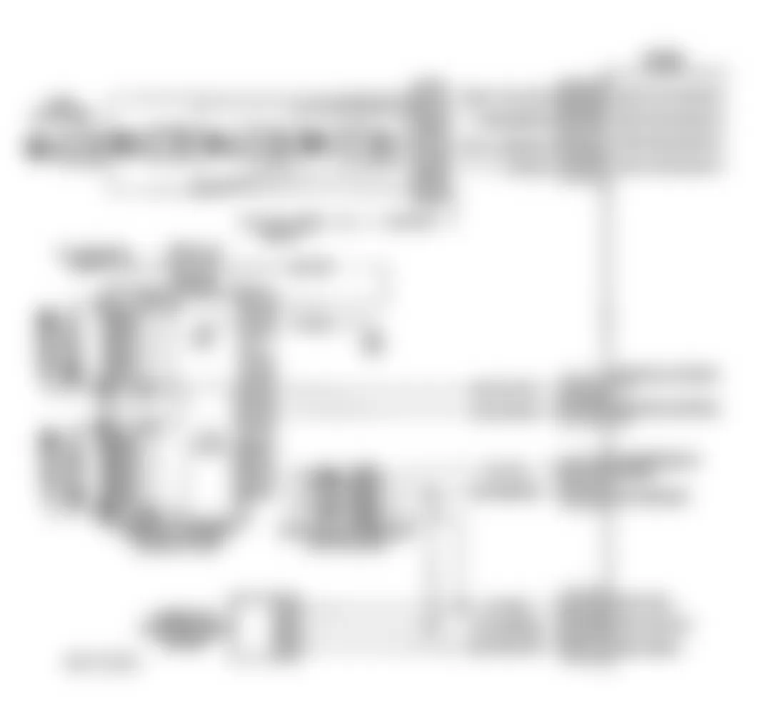
Isuzu Hombre S 1996 - Circuit Description
Powertrain Control Module (PCM) monitors Crankshaft Position (CKP) sensor and Camshaft Position (CMP) sensor to detect if engine is misfiring. PCM looks for a sudden drop in crankshaft speed. This test is executed in blocks of 100 camshaft revolution tests. It may take several tests to set a DTC. Under light misfire conditions, it may take more than one trip to set a DTC. Severe misfire will flash Malfunction Indicator Light (MIL), indicating catalytic converter damage is possible.
Conditions for setting this DTC are as follows:
- Misfire total is 12 counts or more.
- TP sensor angle has not changed more than 8 percent in one second.
- Engine run time is more than 15 seconds.
- Battery output 9-17 volts.
- Engine coolant temperature between 20?F and 254?F (-7?C and 123?C)
- Engine speed is 469-3400 RPM.
Isuzu Hombre S 1996 - Diagnostic Procedures
- Perform On-Board Diagnostic (OBD) System Check. After performing OBD system check, go to next step.
- If any other DTCs are set, diagnose DTCs as necessary before proceeding. If no other DTCs are set, go to next step.
- Perform a visual inspection of the following. Check vacuum hoses for splits, kinks and proper routing. Check for leaks at throttle body, intake manifold, EGR valve and PCV system. Check PCM grounds for proper connection. Check injector harness connectors for proper installation. Repair as necessary. If no problems are found, go to next step. After repair is completed, go to step 34).
- Start engine and allow it to idle. Using scan tool, select MISFIRE DATA LIST function and monitor MISFIRE CUR. COUNTERS (one counter per cylinder). If any MISFIRE CURRENT counters are incrementing, go to next step. If MISFIRE CURRENT counters are not incrementing, go to step 6).
- If all counters noted in step 4) are equal (within one percent of each other), go to step 7). If all counters are not equal, go to step 11).
- Turn ignition on, with engine off. Using scan tool, review FREEZE FRAME data and note parameters. Start engine and operate vehicle within conditions required for setting this DTC, and as close to conditions recorded in FREEZE FRAME as possible. If any of MISFIRE CURRENT counters are incrementing, go to step 5). If MISFIRE CURRENT counters are not incrementing, see DIAGNOSTIC AIDS.
- Turn ignition off. Install fuel pressure gauge. Start engine and allow it to idle. If fuel pressure is 41-47 psi (284-325 Kg cm2 ), go to next step. If fuel pressure is not 41-47 psi (284-325 Kg cm2 ), see BASIC FUEL SYSTEM CHECKS (A-7) in BASIC TESTING article.
- Check for fuel contamination. If fuel is contaminated, go to step 10). If fuel is not contaminated, go to next step.
- Check for a basic engine problem (compression, cam timing, throttle body leak, restricted airflow. etc.). Repair as necessary. After repair is completed, go to step 34).
- Replace contaminated fuel. After repair has been completed, go to step 34).
- Turn ignition off. Disconnect all fuel injector connectors. Install injector test light on injector harness connector for cylinder that misfired. Crank engine and observe test light. If test light flashes, go to next step. If test light does not flash, go to step 13).
- Perform INJECTOR BALANCE TEST. See FUEL SYSTEM in SYSTEM/COMPONENT TESTS article. If all injectors are okay, go to step 14). If any injector is not okay, go to step 16).
- Remove injector test light. Connect a test light between ground and ignition feed terminal at injector harness connector. Crank engine and observe test light. If test light is on, go to step 17). If test light is off, go to step 26).
- Turn ignition off. Disconnect fuel injector harness connector. Install Spark Tester (J-26792) to cylinder No. 1 spark plug wire. Crank engine and check for spark. Repeat spark check for remaining cylinders. If spark is present at all plug wires, go to step 29). If spark is not present at all plug wires, go to step 20).
- Turn ignition off. Disconnect fuel injector connector. Disconnect Ignition Control Module (ICM) 6-pin connector. Connect one lead of DVOM to ground. While cranking engine, using other lead of DVOM, probe terminal "D" then terminal "E" at ICM harness connector. If frequency reading is 1-10 Hz, go to step 22). If frequency reading is not 1-10 Hz, go to step 21).
- Replace defective fuel injector(s). After repair is completed, go to step 34).
- Check suspect fuel injector driver circuit(s) for an open, short to ground or short to voltage. If circuit fault is found, go to next step. If circuit is okay, go to step 19).
- Repair open or shorted circuit(s) as necessary. After repair is completed, go to step 34).
- Repair open ignition feed circuit as necessary. After repair is completed, go to step 34).
- Measure resistance of spark plug wire that spark tester indicated had no spark. If resistance is less than 3000 ohms, go to step 15). If resistance is 3000 ohms or more, go to step 32).
- Turn ignition on, with engine off. With DVOM connected to ground, measure voltage at ICM harness connector terminal that frequency was not 1-10 Hz. If voltage is less than .5 volt, go to step 23). If voltage is .5 volt or more, go to step 27).
- Remove ignition coil from cylinder that did not have spark. Measure secondary resistance of ignition coil. If resistance is 5000-8000 ohms, go to step 24). If resistance is not 5000-8000 ohms, go to step 30).
- Turn ignition off. Connect a test light between positive battery terminal and ICM harness connector terminal that voltage was less than .5 volt. If test light is on, go to step 33). If test light is off, go to step 25).
- Install a known-good ignition coil. Reconnect ICM connector. With spark tester connected to spark plug wire of suspect cylinder, crank engine and observe spark tester. If spark is present, go to step 30). If spark is not present, go to step 28).
- Repair open in suspect ignition control circuit. After repair is completed, go to step 34).
- Repair open ignition feed circuit as necessary. After repair is completed, go to step 34).
- Repair short to voltage in suspect ignition control circuit. After repair is completed, go to step 34).
- Replace ICM. After repair is completed, go to step 34).
- Replace defective spark plug(s) as necessary. After repair is completed, go to step 34).
- Replace defective coil. After repair is completed, go to step 34).
- Replace PCM. Program replacement PCM using required equipment. After repair is completed, go to step 34).
- Replace defective spark plug wire. After repair is completed, go to step 34).
- Check for short to ground in ignition control circuits "A" and "B". Repair wiring as necessary. 10). After repair is completed, go to next step. If circuits are okay, go to step 31).
- Using scan tool, select CLEAR INFO or CLEAR DTCS function to clear DTCs. Start engine and allow it to idle. Ensure engine is at normal operating temperature. Operate vehicle within conditions required for setting this DTC. Select SPECIFIC DTC function then enter DTC P0300. If scan tool indicates TEST RAN AND PASSED, go to next step. If scan tool does not indicate TEST RAN AND PASSED, repeat step 2).
- If any other DTCs are set, diagnose DTCs as necessary. If no other DTCs are set, no problem is indicated at this time.
Isuzu Hombre S 1996 - Diagnostic Aids
A intermittent can be caused by a defective CKP sensor reluctor wheel. Remove CKP sensor. Inspect reluctor wheel through CKP sensor mounting hole. Check porosity and condition of reluctor wheel. If reluctor wheel is okay, see TESTS W/O CODES article for intermittent diagnosis.
Isuzu Hombre S 1996 - DTC P0301 - CYLINDER NO. 1 MISFIRE DETECTED
NOTE: For circuit reference, see Code P0300 schematic.
Isuzu Hombre S 1996 - Circuit Description
Powertrain Control Module (PCM) monitors Crankshaft Position (CKP) sensor and Camshaft Position (CMP) sensor to detect if engine is misfiring. PCM looks for a sudden drop in crankshaft speed. This test is executed in blocks of 100 camshaft revolution tests. It may take several tests to set a DTC. Under light misfire conditions, it may take more than one trip to set a DTC. Severe misfire will flash Malfunction Indicator Light (MIL) indicating that catalytic converter damage is possible.
Conditions for setting this DTC are as follows:
- Misfire total is 12 counts or more.
- TP sensor angle has not changed more than 8 percent in one second.
- Battery output of 9-17 volts.
- Engine coolant temperature between 20?F and 254?F (-7?C and 123?C).
- Engine run time is more than 15 seconds.
- Engine speed is 469-3400 RPM.
Isuzu Hombre S 1996 - Diagnostic Procedures
- Perform On-Board Diagnostic (OBD) System Check. After performing OBD system check, go to next step.
- If any other DTCs are set, diagnose DTCs as necessary before proceeding. If no other DTCs are set, go to next step.
- Perform a visual inspection of the following. Check vacuum hoses for splits, kinks and proper routing. Check for leaks at throttle body, intake manifold, EGR valve and PCV system. Check PCM grounds for proper connection. Check injector harness connectors for proper installation. Repair as necessary. If no problems are found, go to next step. After repair is completed, go to step 6).
- Start engine and allow it to idle. Using scan tool, select MISFIRE DATA LIST function and monitor MISFIRE CUR. COUNTERS (one counter per cylinder). If MISFIRE CURRENT NO. 1 counter is incrementing, go to next step. If MISFIRE CURRENT NO. 1 counter is not incrementing, go to step 6).
- Turn ignition off. Disconnect fuel injector harness connector. Install Spark Tester (J-26792) to cylinder No. 1 spark plug wire. Remove No. 4 spark plug wire from ignition coil. Connect a jumper wire between ground and ignition coil tower (where No. 4 spark plug wire was). Crank engine and check for spark. If spark is present, go to step 8). If spark is not present, go to step 9).
- Turn ignition on, with engine off. Using scan tool, review FREEZE FRAME data and note parameters. Start engine and operate vehicle within conditions required for setting this DTC, and as close to conditions recorded in FREEZE FRAME as possible. If MISFIRE CURRENT NO. 1 counter is incrementing, go to step 5). If MISFIRE CURRENT NO. 1 counter is not incrementing, go to next step.
- If no problems were found in visual inspection, go to DIAGNOSTIC AIDS. If a repair was made after visual inspection was performed in step 3), go to step 30).
- Remove spark plug from No. 1 cylinder. Replace spark plug with a known-good spark plug. Reconnect fuel injection harness connector. Operate vehicle within misfire conditions as recorded in FREEZE FRAME. If MISFIRE CURRENT NO. 1 counter is incrementing, go tostep 13). If MISFIRE CURRENT NO. 1 counter is not incrementing, go to step 22).
- Remove spark plug wire from No. 1 cylinder. Using DVOM, measure plug wire resistance. If resistance is less than 3000 ohms, go to next step. If resistance is 3000 ohms or more, go to step 23).
- Remove ignition coil from cylinder that did not have spark. Measure secondary resistance of coil. If resistance is not 5000-8000 ohms, go to step 24). If resistance is 5000-8000 ohms, go to next step.
- Replace coil with a known-good coil. Crank engine and check for spark. If spark is present, go to step 24). If spark is not present, go to next step.
- Disconnect and inspect Ignition Control Module (ICM) 6-pin connector. Repair as necessary. If connector is okay, go to step 25). After repair is completed, go to step 30).
- Turn ignition off. Disconnect all fuel injector connectors. Install injector test light on injector harness connector for No. 1 cylinder. Crank engine and observe test light. If test light flashes, go to next step. If test light does not flash, go to step 15).
- Perform INJECTOR BALANCE TEST. See FUEL SYSTEM in SYSTEM/COMPONENT TESTS article. If No. 1 injector is okay, go to step 28). If No. 1 injector is not okay, go to step 29).
- Remove injector test light. Connect a test light between ground and ignition feed terminal at No. 1 injector harness connector. Crank engine and observe test light. If test light is on, go to next step. If test light is off, go to step 27).
- Turn ignition off. Disconnect PCM connectors. With test light connected to ground, probe injector driver circuit terminal at No. 1 injector harness connector. If test light is off, go to next step. If test light is on, go to step 26).
- With test light connected to positive battery terminal, probe injector No. 1 driver circuit terminal at No. 1 injector harness connector. If test light is off, go to next step. If test light is on, go to step 19).
- Inspect PCM connectors for damaged pins, corrosion and loose wires. If connectors are okay, go to step 20). If connectors are not okay, go to step 21).
- Repair short to ground in cylinder No. 1 fuel injector driver circuit. After repair is completed, go to step 30).
- Replace PCM. Reprogram replacement PCM. After repair is completed, go to step 30).
- Repair connector or connections as necessary. After repair is completed, go to step 30).
- Replace spark plug. After repair is completed, go to step 30).
- Replace spark plug wire. After repair is completed, go to step 30).
- Replace ignition coil. After repair is completed, go to step 30).
- Replace ICM. After repair is completed, go to step 30).
- Repair short to voltage in cylinder No. 1 fuel injector driver circuit. After repair is completed, go to step 30).
- Repair open in ignition feed circuit. After repair is completed, go to step 30).
- Check for a basic engine problem (compression, cam timing, throttle body leak, restricted air flow. etc.). Repair as necessary. After repair is completed, go to step 30).
- Replace defective fuel injector. After repair is completed, go to next step.
- Using scan tool, select CLEAR INFO or CLEAR DTCS function to clear DTCs. Start engine and allow it to idle. Ensure engine is at normal operating temperature. Operate vehicle within conditions required for setting this DTC. Select SPECIFIC DTC function then enter DTC P0301. If scan tool indicates TEST RAN AND PASSED, go to next step. If scan tool does not indicate TEST RAN AND PASSED, repeat step 2).
- If any other DTCs are set, diagnose DTCs as necessary. If no other DTCs are set, no problem is indicated at this time.
Isuzu Hombre S 1996 - Diagnostic Aids
An intermittent can be caused by a defective CKP sensor reluctor wheel. Remove CKP sensor. Inspect reluctor wheel through CKP sensor mounting hole. Check porosity and condition of reluctor wheel. If reluctor wheel is okay, see appropriate TESTS W/O CODES article for intermittent diagnosis.
Isuzu Hombre S 1996 - DTC P0302 - CYLINDER NO. 2 MISFIRE DETECTED
NOTE: For circuit reference, see Code P0300 schematic.
Isuzu Hombre S 1996 - Circuit Description
Powertrain Control Module (PCM) monitors Crankshaft Position (CKP) sensor and Camshaft Position (CMP) sensor to detect if engine is misfiring. PCM looks for a sudden drop in crankshaft speed. This test is executed in blocks of 100 camshaft revolution tests. It may take several tests to set a DTC. Under light misfire conditions, it may take more than one trip to set a DTC. Severe misfire will flash Malfunction Indicator Light (MIL) indicating that catalytic converter damage is possible.
Conditions for setting this DTC are as follows:
- Misfire total is 12 counts or more.
- TP sensor angle has not changed more than 8 percent in one second.
- Engine run time is more than 15 seconds.
- Battery output at 9-17 volts.
- Engine coolant temperature between 20?F and 254?F (-7?C and 123?C).
- No presence of Codes: P0106, P0107, P0112, P0113, P0117, P0118, P0121-P0123, P0125, P0131, P0133, P0134, P0171, P0172, P0325, P0335, P0341, P0342, P0401, P0502, P0503, P0601, P1133, P1406, P1441.
- Engine speed is 469-3400 RPM.
Isuzu Hombre S 1996 - Diagnostic Procedures
- Perform On-Board Diagnostic (OBD) System Check. After performing OBD system check, go to next step.
- If any other DTCs are set, diagnose DTCs as necessary before proceeding. If no other DTCs are set, go to next step.
- Perform a visual inspection of the following. Check vacuum hoses for splits, kinks and proper routing. Check for leaks at throttle body, intake manifold, EGR valve and PCV system. Check PCM grounds for proper connection. Check injector harness connectors for proper installation. Repair as necessary. If no problems are found, go to next step. After repair is completed, go to step 6).
- Start engine and allow it to idle. Using scan tool, select MISFIRE DATA LIST function and monitor MISFIRE CUR. COUNTERS (one counter per cylinder). If MISFIRE CURRENT NO. 2 counter is incrementing, go to next step. If MISFIRE CURRENT NO. 2 counter is not incrementing, go to step 6).
- Turn ignition off. Disconnect fuel injector harness connector. Install Spark Tester (J-26792 ) to cylinder No. 2 spark plug wire. Remove No. 3 spark plug wire from ignition coil. Connect a jumper wire between ground and ignition coil tower (where No. 3 spark plug wire was). Crank engine and check for spark. If spark is present, go to step 8). If spark is not present, go to step 9).
- Turn ignition on, with engine off. Using scan tool, review FREEZE FRAME data and note parameters. Start engine and operate vehicle within conditions required for setting this DTC, and as close to conditions recorded in FREEZE FRAME as possible. If MISFIRE CURRENT NO. 2 counter is incrementing, go to step 5). If MISFIRE CURRENT NO. 2 counter is not incrementing, go to next step.
- If no problems were found in visual inspection, go to DIAGNOSTIC AIDS. If a repair was made after visual inspection was performed in step 3), go to step 30).
- Remove spark plug from No. 2 cylinder. Replace spark plug with a known-good spark plug. Reconnect fuel injection harness connector. Operate vehicle within misfire conditions as recorded in FREEZE FRAME. If MISFIRE CURRENT NO. 2 counter is incrementing properly, go to step 13). If MISFIRE CURRENT NO. 2 counter is not incrementing properly, go to step 22).
- Remove spark plug wire from No. 2 cylinder. Using DVOM, measure plug wire resistance. If resistance is less than 3000 ohms, go to next step. If resistance is 3000 ohms or more, go to step 23).
- Remove ignition coil from cylinder that did not have spark. Measure secondary resistance of coil. If resistance is not 5000-8000 ohms, go to step 24). If resistance is 5000-8000 ohms, go to next step.
- Replace coil with a known-good coil. Crank engine and check for spark. If spark is present, go to step 24). If spark is not present, go to next step.
- Disconnect and inspect Ignition Control Module (ICM) 6-pin connector. Repair as necessary. If connector is okay, go to step 25). After repair is completed, go to step 30).
- Turn ignition off. Disconnect all fuel injector connectors. Install injector test light on injector harness connector for No. 2 cylinder. Crank engine and observe test light. If test light flashes, go to next step. If test light does not flash, go to step 15).
- Perform INJECTOR BALANCE TEST. See FUEL SYSTEM in SYSTEM/COMPONENT TESTS article. If No. 2 injector is okay, go to step 28). If No. 2 injector is not okay, go to step 29).
- Remove injector test light. Connect a test light between ground and ignition feed terminal at No. 2 injector harness connector. Crank engine and observe test light. If test light is on, go to next step. If test light is off, go to step 27).
- Turn ignition off. Disconnect PCM connectors. With test light connected to ground, probe injector driver circuit terminal at No. 2 injector harness connector. If test light is off, go to next step. If test light is on, go to step 26).
- With test light connected to positive battery terminal, probe injector driver circuit terminal at No. 2 injector harness connector. If test light is off, go to next step. If test light is on, go to step 19).
- Inspect PCM connectors for damaged pins, corrosion and loose wires. If connectors are okay, go to step 20). If connectors are not okay, go to step 21).
- Repair short to ground in cylinder No. 2 fuel injector driver circuit. After repair is completed, go to step 30).
- Replace PCM. Program replacement PCM using required equipment. After repair is completed, go to step 30).
- Repair connector or connections as necessary. After repair is completed, go to step 30).
- Replace spark plug. After repair is completed, go to step 30).
- Replace spark plug wire. After repair is completed, go to step 30).
- Replace ignition coil. After repair is completed, go to step 30).
- Replace ICM. After repair is completed, go to step 30).
- Repair short to voltage in cylinder No. 2 fuel injector driver circuit. After repair is completed, go to step 30).
- Repair open in ignition feed circuit. After repair is completed, go to step 30).
- Check for a basic engine problem (compression, cam timing, throttle body leak, restricted air flow. etc.). Repair as necessary. After repair is completed, go to step 30).
- Replace defective fuel injector. After repair is completed, go to next step.
- Using scan tool, select CLEAR INFO or CLEAR DTCS function to clear DTCs. Start engine and allow it to idle. Ensure engine is at normal operating temperature. Operate vehicle within conditions required for setting this DTC. Select SPECIFIC DTC function then enter DTC P0302. If scan tool indicates TEST RAN AND PASSED, go to next step. If scan tool does not indicate TEST RAN AND PASSED, repeat step 2).
- If any other DTCs are set, diagnose DTCs as necessary. If no other DTCs are set, no problem is indicated at this time.
Isuzu Hombre S 1996 - Diagnostic Aids
An intermittent can be caused by a defective CKP sensor reluctor wheel. Remove CKP sensor. Inspect reluctor wheel through CKP sensor mounting hole. Check porosity and condition of reluctor wheel. If reluctor wheel is okay, see TESTS W/O CODES article for intermittent diagnosis.
Isuzu Hombre S 1996 - DTC P0303 - CYLINDER NO. 3 MISFIRE DETECTED
NOTE: For circuit reference, see Code P0300 schematic.
Isuzu Hombre S 1996 - Circuit Description
Powertrain Control Module (PCM) monitors Crankshaft Position (CKP) sensor and Camshaft Position (CMP) sensor to detect if engine is misfiring. PCM looks for a sudden drop in crankshaft speed. This test is executed in blocks of 100 camshaft revolution tests. It may take several tests to set a DTC. Under light misfire conditions, it may take more than one trip to set a DTC. Severe misfire will flash Malfunction Indicator Light (MIL) indicating that catalytic converter damage is possible.
Conditions for setting this DTC are as follows:
- Misfire total is 12 counts or more.
- TP sensor angle has not changed more than 8 percent in one second.
- Engine run time is more than 15 seconds.
- Battery output at 9-17 volts.
- Engine coolant temperature between 20?F and 254?F (-7?C and 123?C).
- No presence of Codes: P0106, P0107, P0112, P0113, P0117, P0118, P0121-P0123, P0125, P0131, P0133, P0134, P0171, P0172, P0325, P0335, P0341, P0342, P0401, P0502, P0503, P0601, P1133, P1406, P1441.
- Engine speed is 469-3400 RPM.
Isuzu Hombre S 1996 - Diagnostic Procedures
- Perform On-Board Diagnostic (OBD) System Check. After performing OBD system check, go to next step.
- If any other DTCs are set, diagnose DTCs as necessary before proceeding. If no other DTCs are set, go to next step.
- Perform a visual inspection of the following. Check vacuum hoses for splits, kinks and proper routing. Check for leaks at throttle body, intake manifold, EGR valve and PCV system. Check PCM grounds for proper connection. Check injector harness connectors for proper installation. Repair as necessary. If no problems are found, go to next step. After repair is completed, go to step 6).
- Start engine and allow it to idle. Using scan tool, select MISFIRE DATA LIST function and monitor MISFIRE CUR. COUNTERS (one counter per cylinder). If MISFIRE CURRENT NO. 3 counter is incrementing, go to next step. If MISFIRE CURRENT NO. 3 counter is not incrementing, go to step 6).
- Turn ignition off. Disconnect fuel injector harness connector. Install Spark Tester (J-26792) to cylinder No. 3 spark plug wire. Remove No. 2 spark plug wire from ignition coil. Connect a jumper wire between ground and ignition coil tower (where No. 2 spark plug wire was). Crank engine and check for spark. If spark is present, go to step 8). If spark is not present, go to step 9).
- Turn ignition on, with engine off. Using scan tool, review FREEZE FRAME data and note parameters. Start engine and operate vehicle within conditions required for setting this DTC, and as close to conditions recorded in FREEZE FRAME as possible. If MISFIRE CURRENT NO. 3 counter is incrementing, go to step 5). If MISFIRE CURRENT NO. 3 counter is not incrementing, go to next step.
- If no problems were found in visual inspection, go to DIAGNOSTIC AIDS. If a repair was made after visual inspection was performed in step 3), go to step 30).
- Remove spark plug from No. 3 cylinder. Replace spark plug with a known-good spark plug. Reconnect fuel injection harness connector. Operate vehicle within misfire conditions as recorded in FREEZE FRAME. If MISFIRE CURRENT NO. 3 counter is incrementing properly, go to step 13). If MISFIRE CURRENT NO. 3 counter is not incrementing properly, go to step 22).
- Remove spark plug wire from No. 3 cylinder. Using DVOM, measure plug wire resistance. If resistance is less than 3000 ohms, go to next step. If resistance is 3000 ohms or more, go to step 23).
- Remove ignition coil from cylinder that did not have spark. Measure secondary resistance of coil. If resistance is not 5000-8000 ohms, go to step 24). If resistance is 5000-8000 ohms, go to next step.
- Replace coil with a known-good coil. Crank engine and check for spark. If spark is present, go to step 24). If spark is not present, go to next step.
- Disconnect and inspect Ignition Control Module (ICM) 6-pin connector. Repair as necessary. If connector is okay, go to step 25). After repair is completed, go to step 30).
- Turn ignition off. Disconnect all fuel injector connectors. Install injector test light on injector harness connector for No. 3 cylinder. Crank engine and observe test light. If test light flashes, go to next step. If test light does not flash, go to step 15).
- Perform INJECTOR BALANCE TEST. See FUEL SYSTEM in SYSTEM/COMPONENT TESTS article. If No. 3 injector is okay, go to step 28). If No. 3 injector is not okay, go to step 29).
- Remove injector test light. Connect a test light between ground and ignition feed terminal at No. 3 injector harness connector. Crank engine and observe test light. If test light is on, go to next step. If test light is off, go to step 27).
- Turn ignition off. Disconnect PCM connectors. With test light connected to ground, probe injector driver circuit terminal at No. 3 injector harness connector. If test light is off, go to next step. If test light is on, go to step 26).
- With test light connected to positive battery terminal, probe injector driver circuit terminal at No. 3 injector harness connector. If test light is off, go to next step. If test light is on, go to step 19).
- Inspect PCM connectors for damaged pins, corrosion and loose wires. If connectors are okay, go to step 20). If connectors are not okay, go to step 21).
- Repair short to ground in cylinder No. 3 fuel injector driver circuit. After repair is completed, go to step 30).
- Replace PCM. Program replacement PCM using required equipment. After repair is completed, go to step 30).
- Repair connector or connections as necessary. After repair is completed, go to step 30).
- Replace spark plug. After repair is completed, go to step 30).
- Replace spark plug wire. After repair is completed, go to step 30).
- Replace ignition coil. After repair is completed, go to step 30).
- Replace ICM. After repair is completed, go to step 30).
- Repair short to voltage in cylinder No. 3 fuel injector driver circuit. After repair is completed, go to step 30).
- Repair open in ignition feed circuit. After repair is completed, go to step 30).
- Check for a basic engine problem (cam timing, throttle body leak, restricted air flow. etc.). Repair as necessary. After repair is completed, go to step 30).
- Replace defective fuel injector. After repair is completed, go to next step.
- Using scan tool, select CLEAR INFO or CLEAR DTCS function to clear DTCs. Start engine and allow it to idle. Ensure engine is at normal operating temperature. Operate vehicle within conditions required for setting this DTC. Select SPECIFIC DTC function then enter DTC P0303. If scan tool indicates TEST RAN AND PASSED, go to next step. If scan tool does not indicate TEST RAN AND PASSED, repeat step 2).
- If any other DTCs are set, diagnose DTCs as necessary. If no other DTCs are set, no problem is indicated at this time.
Isuzu Hombre S 1996 - Diagnostic Aids
An intermittent can be caused by a defective CKP sensor reluctor wheel. Remove CKP sensor. Inspect reluctor wheel through CKP sensor mounting hole. Check porosity and condition of reluctor wheel. If reluctor wheel is okay, see TESTS W/O CODES article for intermittent diagnosis.
Isuzu Hombre S 1996 - DTC P0304 - CYLINDER NO. 4 MISFIRE DETECTED
NOTE: For circuit reference, see Code P0300 schematic.
Isuzu Hombre S 1996 - Circuit Description
Powertrain Control Module (PCM) monitors Crankshaft Position (CKP) sensor and Camshaft Position (CMP) sensor to detect if engine is misfiring. PCM looks for a sudden drop in crankshaft speed. This test is executed in blocks of 100 camshaft revolution tests. It may take several tests to set a DTC. Under light misfire conditions, it may take more than one trip to set a DTC. Severe misfire will flash Malfunction Indicator Light (MIL) indicating that catalytic converter damage is possible.
Conditions for setting this DTC are as follows:
- Misfire total is 12 counts or more.
- TP sensor angle has not changed more than 8 percent in one second.
- Engine run time is more than 15 seconds.
- Battery output at 9-17 volts.
- Engine coolant temperature between 20?F and 254?F (-7?C and 123?C).
- No presence of Codes: P0106, P0107, P0112, P0113, P0117, P0118, P0121-P0123, P0125, P0131, P0133, P0134, P0171, P0172, P0325, P0335, P0341, P0342, P0401, P0502, P0503, P0601, P1133, P1406, P1441.
- Engine speed is 469-3400 RPM.
Isuzu Hombre S 1996 - Diagnostic Procedures
- Perform On-Board Diagnostic (OBD) System Check. After performing OBD system check, go to next step.
- If any other DTCs are set, diagnose DTCs as necessary before proceeding. If no other DTCs are set, go to next step.
- Perform a visual inspection of the following. Check vacuum hoses for splits, kinks and proper routing. Check for leaks at throttle body, intake manifold, EGR valve and PCV system. Check PCM grounds for proper connection. Check injector harness connectors for proper installation. Repair as necessary. If no problems are found, go to next step. After repair is completed, go to step 6).
- Start engine and allow it to idle. Using scan tool, select MISFIRE DATA LIST function and monitor MISFIRE CUR. COUNTERS (one counter per cylinder). If MISFIRE CURRENT NO. 4 counter is incrementing, go to next step. If MISFIRE CURRENT NO. 4 counter is not incrementing, go to step 6).
- Turn ignition off. Disconnect fuel injector harness connector. Install Spark Tester (J-26792) to cylinder No. 4 spark plug wire. Remove No. 1 spark plug wire from ignition coil. Connect a jumper wire between ground and ignition coil tower (where No. 1 spark plug wire was). Crank engine and check for spark. If spark is present, go to step 8). If spark is not present, go to step 9).
- Turn ignition on, with engine off. Using scan tool, review FREEZE FRAME data and note parameters. Start engine and operate vehicle within conditions required for setting this DTC, and as close to conditions recorded in FREEZE FRAME as possible. If MISFIRE CURRENT NO. 4 counter is incrementing, go to step 5). If MISFIRE CURRENT NO. 4 counter is not incrementing, go to next step.
- If no problems were found in visual inspection, go to DIAGNOSTIC AIDS. If a repair was made after visual inspection was performed in step 3), go to step 30).
- Remove spark plug from No. 4 cylinder. Replace spark plug with a known-good spark plug. Reconnect fuel injection harness connector. Operate vehicle within misfire conditions as recorded in FREEZE FRAME. If MISFIRE CURRENT NO. 4 counter is incrementing properly, go to step 13). If MISFIRE CURRENT NO. 4 counter is not incrementing properly, go to step 22).
- Remove spark plug wire from No. 4 cylinder. Using DVOM, measure plug wire resistance. If resistance is less than 3000 ohms, go to next step. If resistance is 3000 ohms or more, go to step 23).
- Remove ignition coil from cylinder that did not have spark. Measure secondary resistance of coil. If resistance is not 5000-8000 ohms, go to step 24). If resistance is 5000-8000 ohms, go to next step.
- Replace coil with a known-good coil. Crank engine and check for spark. If spark is present, go to step 24). If spark is not present, go to next step.
- Disconnect and inspect Ignition Control Module (ICM) 6-pin connector. Repair as necessary. If connector is okay, go to step 25). After repair is completed, go to step 30).
- Turn ignition off. Disconnect all fuel injector connectors. Install injector test light on injector harness connector for No. 4 cylinder. Crank engine and observe test light. If test light flashes, go to next step. If test light does not flash, go to step 15).
- Perform INJECTOR BALANCE TEST. See FUEL SYSTEM in appropriate SYSTEM/COMPONENT TESTS article. If No. 4 injector is okay, go to step 28). If No. 4 injector is not okay, go to step 29).
- Remove injector test light. Connect a test light between ground and ignition feed terminal at No. 4 injector harness connector. Crank engine and observe test light. If test light is on, go to next step. If test light is off, go to step 27).
- Turn ignition off. Disconnect PCM connectors. With test light connected to ground, probe injector driver circuit terminal at No. 4 injector harness connector. If test light is off, go to next step. If test light is on, go to step 26).
- With test light connected to positive battery terminal, probe injector driver circuit terminal at No. 4 injector harness connector. If test light is off, go to next step. If test light is on, go to step 19).
- Inspect PCM connectors for damaged pins, corrosion and loose wires. If connectors are okay, go to step 20). If connectors are not okay, go to step 21).
- Repair short to ground in cylinder No. 4 fuel injector driver circuit. After repair is completed, go to step 30).
- Replace PCM. Program replacement PCM using required equipment. After repair is completed, go to step 30).
- Repair connector or connections as necessary. After repair is completed, go to step 30).
- Replace spark plug. After repair is completed, go to step 30).
- Replace spark plug wire. After repair is completed, go to step 30).
- Replace ignition coil. After repair is completed, go to step 30).
- Replace ICM. After repair is completed, go to step 30).
- Repair short to voltage in cylinder No. 4 fuel injector driver circuit. After repair is completed, go to step 30).
- Repair open in ignition feed circuit. After repair is completed, go to step 30).
- Check for a basic engine problem (cam timing, throttle body leak, restricted air flow. etc.). Repair as necessary. After repair is completed, go to step 30).
- Replace defective fuel injector. After repair is completed, go to next step.
- Using scan tool, select CLEAR INFO or CLEAR DTCS function to clear DTCs. Start engine and allow it to idle. Ensure engine is at normal operating temperature. Operate vehicle within conditions required for setting this DTC. Select SPECIFIC DTC function then enter DTC P0304. If scan tool indicates TEST RAN AND PASSED, go to next step. If scan tool does not indicate TEST RAN AND PASSED, repeat step 2).
- If any other DTCs are set, diagnose DTCs as necessary. If no other DTCs are set, no problem is indicated at this time.
Isuzu Hombre S 1996 - Diagnostic Aids
An intermittent can be caused by a defective CKP sensor reluctor wheel. Remove CKP sensor. Inspect reluctor wheel through CKP sensor mounting hole. Check porosity and condition of reluctor wheel. If reluctor wheel is okay, see TESTS W/O CODES article for intermittent diagnosis.
Isuzu Hombre S 1996 - DTC P0325 - KNOCK SENSOR CIRCUIT
Fig. 8: Isuzu Hombre S 1996 - Component Locations - Knock Sensor Circuit (Hombre)

Isuzu Hombre S 1996 - Circuit Description
Knock Sensor (KS) is used to detect engine detonation. PCM will retard spark timing based on signals from KS module. The KS produces an AC signal voltage that is sent to the KS module. The amount of AC voltage produced is proportional to the amount of knock.
Conditions for setting this DTC are as follows:
- Engine speed is 2200-6375 RPM.
- TP sensor angle is greater than 5 percent.
- No presence of Codes: P0117, P0118, P0122, P0123.
- KS voltage is less than .19 volt or greater than 4.99 volt.
Isuzu Hombre S 1996 - Diagnostic Procedures
- Perform On-Board Diagnostic (OBD) System Check. After performing OBD system check, go to next step.
- Start engine. Using scan tool, select CLEAR INFO or CLEAR DTCS function to clear DTCs. Operate engine at 10 percent throttle angle. Check Malfunction Indicator Light (MIL). If MIL is on, go to 4). If MIL is off, go to next.
- Turn ignition on, with engine off. Using scan tool, review FREEZE FRAME data and note parameters. Start engine and operate vehicle within conditions required for setting this DTC, and as close to conditions recorded in FREEZE FRAME as possible. If MIL is on, go to next step. If MIL is off, go to step 15)
- While listening to engine, raise and lower engine RPM. If an audible noise or knock is present, go to next step. If no audible noise or knock is present, go to step 6)
- Repair cause of engine noise or knock. After repair is completed, go to step 15).
- Slowly increase engine speed to 2500 RPM. Using scan tool, monitor KS activity. If KS activity increases with engine speed, go to next step. If KS activity does not increase with engine speed, go to step 11).
- Check for a poor KS signal circuit terminal connection at PCM connector. Repair as necessary. After repair is completed, go to step 15). If terminal connection is okay, go to next step.
- If KS module has previously been replaced, go to next step. If KS module has not previously been replaced, go to step 10).
- Replace PCM. Program replacement PCM using required equipment. After repair is completed, go to step 15).
- Replace KS module. After repair is completed, go to step 15).
- Turn ignition off. Disconnect PCM connectors. Measure resistance between ground and signal circuit terminal at PCM connector. If resistance is 90-110 k/ohms, go to step 7). If resistance is not 90-110 k/ohms, go to next step.
- Check KS connector for poor connection. Repair as necessary. After repair is completed, go to step 15). If connector is okay, go to next step.
- Check KS signal circuit for an open, short to ground or short to voltage. Repair as necessary. After repair is completed, go to step 15). If circuit is okay, go to next step.
- Replace KS. After repair is completed, go to next step.
- Using scan tool, select CLEAR INFO or CLEAR DTCS function to clear DTCs. Start engine and allow it to idle. Ensure engine is at normal operating temperature. Operate vehicle within conditions required for setting this DTC. Select SPECIFIC DTC function then enter DTC P0325. If scan tool indicates TEST RAN AND PASSED, go to next step. If scan tool does not indicate TEST RAN AND PASSED, repeat step 2).
- If any other DTCs are set, diagnose DTCs as necessary. If no other DTCs are set, no problem is indicated at this time.
Isuzu Hombre S 1996 - Diagnostic Aids
Check knock sensor for proper connection. A loose or over-torqued knock sensor can cause DTC to set.
Isuzu Hombre S 1996 - DTC P0335 - CRANKSHAFT POSITION (CKP) SENSOR CIRCUIT
NOTE: For circuit reference, see Code P0300 schematic.
Isuzu Hombre S 1996 - Circuit Description
Powertrain Control Module (PCM) supplies battery power and ground to CKP sensor. CKP sensor sends a reference signal to PCM 7 times per revolution to indicate crankshaft position and engine speed. The seventh pulse is the sync pulse and is used for crankshaft position reference. PCM calculates when to pulse ignition coils based on these signals.
Condition for setting this DTC is as follows:
- 7x resync counter is more than 15 counts within 4 minutes and 15 seconds.
Isuzu Hombre S 1996 - Diagnostic Procedures
- Perform On-Board Diagnostic (OBD) System Check. After performing OBD system check, go to next step.
- Using scan tool, select CLEAR INFO or CLEAR DTCS function to clear DTCs. Start engine and allow it to idle for 5 minutes or until Malfunction Indicator Light (MIL) turns on. If MIL is on, go to next step. If MIL is off, go to step 4).
- With engine running, wiggle PCM connectors, CKP sensor connector and related wiring. If engine stumbles, go to step 5). If engine does not stumble, go to step 6).
- Operate any non-engine related accessories on vehicle. If MED. RESOLUTION RESYNC CNTR. on scan tool resyncs while operating accessories, go to step 8). If MED. RESOLUTION RESYNC CNTR. on scan tool does not resync while operating accessories, go to step 3).
- Repair poor connector connection, wiring or connector that caused engine to stumble. After repair is completed, go to step 11).
- If MIL turned on in step 2), go to next step. If MIL did not turn on, go to step 11).
- Check wiring to PCM and CKP sensor for pinched or worn through wire insulation. Repair wiring as necessary. After repair is completed, go to step 11). If wiring is okay, go to step 9).
- Repair faulty circuit or accessory component that caused MED. RESOLUTION RESYNC CNTR. on scan tool to resync. After repair is completed, go to step 11).
- Replace CKP sensor. Start engine and allow it to idle for 5 minutes or until Malfunction Indicator Light (MIL) turns on. If MIL is on, go to next step. If MIL is off, go to step 11).
- Replace PCM. Program replacement PCM using required equipment. After repair is completed, go to next step.
- Using scan tool, select CLEAR INFO or CLEAR DTCS function to clear DTCs. Start engine and allow it to idle. Ensure engine is at normal operating temperature. Operate vehicle within conditions required for setting this DTC. Select SPECIFIC DTC function then enter DTC P0335. If scan tool indicates TEST RAN AND PASSED, go to next step. If scan tool does not indicate TEST RAN AND PASSED, repeat step 2).
- If any other DTCs are set, diagnose DTCs as necessary. If no other DTCs are set, no problem is indicated at this time.
Isuzu Hombre S 1996 - Diagnostic Aids
If complaint is engine cranks but will not run, DTC P0335 may be set if engine is cranked more than 15 times without turning ignition off between starting attempts.
An intermittent can be caused by a defective CKP sensor reluctor wheel. Remove CKP sensor. Inspect reluctor wheel through CKP sensor mounting hole. Check porosity and condition of reluctor wheel. Intermittent can also be caused by a rubbed through wire insulation or a poor connection.
Isuzu Hombre S 1996 - DTC P0341 - CAMSHAFT POSITION (CMP) SENSOR CIRCUIT
NOTE: For circuit reference, see Code P0300 schematic.
Isuzu Hombre S 1996 - Circuit Description
Powertrain Control Module (PCM) uses CMP sensor signal to determine which cylinder is misfiring when a misfire is present. When PCM receives an intermittent signal from CMP sensor, the CMP RESYNC counter will increment.
Conditions for setting this DTC are as follows:
- Engine is running.
- CMP RESYNC counter is greater than 15 counts.
Isuzu Hombre S 1996 - Diagnostic Procedures
- Perform On-Board Diagnostic (OBD) System Check. After performing OBD system check, go to next step.
- Start engine and allow it to idle. Install scan tool. If CMP RESYNC counter is incrementing, go to next step. If CMP RESYNC counter is not incrementing, go to step 4).
- Turn ignition off. Disconnect CMP sensor connector. Turn ignition on. If CMP RESYNC counter is incrementing, go to step 5). If CMP RESYNC counter is not incrementing, go to step 6).
- With engine running, carefully wiggle CMP sensor connector. If CMP RESYNC counter is incrementing, go to next step. If CMP RESYNC counter is not incrementing, go to step 8).
- Check for poor connection at CMP sensor connector. Repair as necessary. After repair is completed, go to step 9). If connector is okay, go to step 7).
- Replace PCM. Program replacement PCM using required equipment. After repair is completed, go to step 9).
- Replace CMP sensor. After repair is completed, go to step 9).
- Turn ignition on, with engine off. Using scan tool, review FREEZE FRAME data and note parameters. Start engine and operate vehicle within conditions required for setting this DTC, and as close to conditions recorded in FREEZE FRAME as possible. If CMP RESYNC counter is incrementing, go to step 3). If CMP RESYNC counter is not incrementing, go to next step.
- Using scan tool, select CLEAR INFO or CLEAR DTCS function to clear DTCs. Start engine and allow it to idle. Ensure engine is at normal operating temperature. Operate vehicle within conditions required for setting this DTC. Select SPECIFIC DTC function then enter DTC P0341. If scan tool indicates TEST RAN AND PASSED, go to next step. If scan tool does not indicate TEST RAN AND PASSED, repeat step 2).
- If any other DTCs are set, diagnose DTCs as necessary. If no other DTCs are set, no problem is indicated at this time.
Isuzu Hombre S 1996 - Diagnostic Aids
An intermittent problem can be caused by a poor connection, rubbed through wire insulation or broken wire inside insulation. Whenever PCM sees less than 15 resyncs in 256 seconds, counter is reset to zero. If a poor CMP sensor connection is present, CAM SENSOR REFERENCE ACTIVITY counter will stop incrementing and CAM SENSOR RESYNC counter will start incrementing.
Isuzu Hombre S 1996 - DTC P0342 - CAMSHAFT POSITION (CMP) SENSOR CIRCUIT LOW
NOTE: For circuit reference, see Code P0300 schematic.
Isuzu Hombre S 1996 - Circuit Description
Powertrain Control Module (PCM) uses CMP sensor signal to determine which cylinder is misfiring when a misfire is present. When PCM receives an intermittent signal from CMP sensor, the CMP ACTIVITY counter will increment.
Conditions for setting this DTC are as follows:
- Engine is running.
- CMP ACTIVITY counter does not increment.
Isuzu Hombre S 1996 - Diagnostic Procedures
- Perform On-Board Diagnostic (OBD) System Check. After performing OBD system check, go to next step.
- Start engine and allow it to idle. Install scan tool. If CMP ACTIVITY counter is incrementing, go to next step. If CMP ACTIVITY counter is not incrementing, go to step 4).
- Turn ignition on, with engine off. Using scan tool, review FREEZE FRAME data and note parameters. Start engine and operate vehicle within conditions required for setting this DTC, and as close to conditions recorded in FREEZE FRAME as possible. If CMP ACTIVITY counter is incrementing, go to step 16). If CMP ACTIVITY counter is not incrementing, go to next step.
- Disconnect CMP sensor connector. With test light connected to ground, probe CMP feed circuit terminal at CMP sensor harness connector. If test light is on, go to next step. If test light is off, go tostep 6).
- With test light connected to positive battery terminal, probe CMP ground circuit terminal at CMP sensor harness connector. If test light is on, go to step 7). If test light is off, go to step 8).
- Check for poor connection at CMP feed circuit at PCM connector. Repair as necessary. After repair is completed, go to step 16). If connection is okay, go to step 15).
- Reconnect CMP sensor connector. Turn ignition off. Disconnect PCM C2 connector. Connect a jumper wire between positive battery terminal and ignition feed circuit terminal (Pink wire) at PCM C2 harness connector. With DVOM connected to ground, probe CMP signal circuit terminal at PCM connector. If voltage varies from zero volts to battery voltage, go to step 15). If voltage does not vary from zero volts to battery voltage, go to step 9).
- Check for poor connection or open in CMP ground circuit. Repair as necessary. After repair is completed, go to step 16). If circuit is okay, go to step 15).
- If DVOM reading in step 7) is a constant voltage (either zero or battery voltage), go to next step. If voltage reading is not a constant voltage, go to step 11).
- Check for a short to voltage in CMP signal circuit. Repair as necessary. After repair is completed, go to step 16). If circuit is okay, go to step 14).
- Disconnect CMP sensor connector. With DVOM connected to positive battery terminal, probe CMP signal circuit terminal at CMP sensor harness connector. If voltage is greater than .5 volt, go to next step. If voltage is .5 volt or less, go to step 13).
- Repair short to ground in CMP signal circuit. After repair is completed, go to step 16).
- Check for poor connection or an open in CMP signal circuit. Repair as necessary. After repair is completed, go to step 16). If circuit is okay, go to next step.
- Replace CMP sensor. After repair is completed, go to step 16).
- Replace PCM. Program replacement PCM using required equipment. After repair is completed, go to next step.
- Using scan tool, select CLEAR INFO or CLEAR DTCS function to clear DTCs. Start engine and allow it to idle. Ensure engine is at normal operating temperature. Operate vehicle within conditions required for setting this DTC. Select SPECIFIC DTC function then enter DTC P0342. If scan tool indicates TEST RAN AND PASSED, go to next step. If scan tool does not indicate TEST RAN AND PASSED, repeat step 2).
- If any other DTCs are set, diagnose DTCs as necessary. If no other DTCs are set, no problem is indicated at this time.
Isuzu Hombre S 1996 - Diagnostic Aids
An intermittent problem can be caused by a poor connection, rubbed through wire insulation or broken wire inside insulation. Whenever PCM sees less than 15 resyncs in 256 seconds, counter is reset to zero. If a poor CMP sensor connection is present, CAM SENSOR REFERENCE ACTIVITY counter will stop incrementing and CAM SENSOR RESYNC counter will start incrementing.
Isuzu Hombre S 1996 - DTC P0401 - EGR SYSTEM INSUFFICIENT FLOW
Fig. 9: Isuzu Hombre S 1996 - Component Locations - EGR System Circuit (Hombre)

Isuzu Hombre S 1996 - Circuit Description
A linear Exhaust Gas Recirculation (EGR) valve is used on this system. Powertrain Control Module (PCM) commands EGR valve to operate when necessary by controlling a ground signal through PCM. This can be monitored on a scan tool by selecting DESIRED EGR POSITION function. Ignition voltage is supplied to EGR valve thorough a fuse. PCM monitors results of its command through a feedback signal. Feedback signal is the actual position of the EGR pintle. This feedback signal can also be monitored on a scan tool by selecting ACTUAL EGR POSITION function. The ACTUAL EGR POSITION should always be near the commanded or DESIRED EGR POSITION.
Conditions for setting this DTC are as follows:
- Engine speed is 1000-2200 RPM.
- Engine coolant temperature is greater than 176?F (80?C).
- Barometric Pressure (BARO) is greater than 60 kPa.
- Manifold Absolute Pressure (MAP) is 13-32 kPa.
- Idle Air Control (IAC) has not changed greater than 4 counts.
- TP angle is less than one percent.
- No presence of Codes: P0106, P0107, P0108, P0112, P0113, P0117, P0118, P0121-P0123, P0125, P0300-P0304, P0335, P0440, P0442, P0446, P0502, P0503, P0506, P0507, P1441.
- Vehicle speed is less than 20 MPH.
- Decel Exponentially Weighted Moving Average (EWMA) is greater than +2 kPa.Z
Isuzu Hombre S 1996 - Diagnostic Procedures
- Perform On-Board Diagnostic (OBD) System Check. After performing OBD system check, go to next step.
- Start engine and allow it to idle. Using scan tool, command EGR valve to 50 percent. If engine stalls or runs rough, go to step 5). If engine dos not stall or run rough, go to next step.
- Turn ignition off. Remove EGR valve. Inspect EGR valve, passages and pipe for restriction or damage. Repair as necessary. After repair is completed, go to step 5). If no problems are found, go to next step.
- Replace EGR valve. After repair is completed, go to next step.
- Disconnect negative battery cable for 10 seconds, then reconnect cable. Road test vehicle. Increase vehicle speed to 60 MPH then release accelerator and allow vehicle to decelerate to 20 MPH. If Decel Exponentially Weighted Moving Average (EWMA) value is greater than zero, return to next step. If EWMA is zero or less, go to step 3).
NOTE: For more information on Decel EWMA, see DIAGNOSTIC AIDS. - Using scan tool, select CLEAR INFO or CLEAR DTCS function to clear DTCs. Start engine and allow it to idle. Ensure engine is at normal operating temperature. Operate vehicle within conditions required for setting this DTC. Select SPECIFIC DTC function then enter DTC P0401. If scan tool indicates TEST RAN AND PASSED, go to next step. If scan tool does not indicate TEST RAN AND PASSED, repeat step 2).
- If any other DTCs are set, diagnose DTCs as necessary. If no other DTCs are set, no problem is indicated at this time.
Isuzu Hombre S 1996 - Diagnostic Aids
Decel Exponentially Weighted Moving Average (EWMA) value is an average of the difference in expected MAP change and actual MAP change caused by opening EGR valve during deceleration. By driving vehicle to 60 MPH and decelerating to 20 MPH, it can be determined if EGR system is okay, partially restricted or fully restricted.
A negative number, less than -3 indicates system is functioning properly. A positive number indicates system is fully restricted and the expected amount of EGR flow is incorrect. A number that falls between -3 and +2 indicates system is partially restricted. The Decel EWMA value should always be -3 or less. If value becomes more positive, check for damaged EGR pipe, restricted EGR passage or defective EGR valve.
Isuzu Hombre S 1996 - DTC P0420 - TWC SYSTEM LOW EFFICIENCY Circuit Description
A 3-Way catalytic converter is used to maintain low emissions. The PCM monitors exhaust gasses from converter using Heated Oxygen Sensor (HO2S). HO2S is located in exhaust stream past the 3-way catalytic converter. HO2S produces an output signal which indicates the oxygen capacity of the catalyst. This determines the catalyst's ability to convert exhaust emissions effectively.
During normal operation, HO2S signal will be less active than that produced by the front Oxygen Sensor (O2S). Powertrain Control Module (PCM) monitors catalyst efficiency in 2 stages. If catalyst efficiency falls to less than 75 percent, PCM will set a stage one fail flag, but will not illuminate Malfunction Indicator Light (MIL). If catalyst efficiency falls to less than 50 percent, PCM will set a stage 2 fail flag and MIL will be illuminated.
Conditions for setting this DTC are:
- Engine speed is 1700-3700 RPM.
- Coolant temperature is greater than 158?F (70?C).
- Vehicle speed is 30-80 MPH.
- No presence of Codes: P0106, P0107, P0108, P0112, P0113, P0117, P0118, P0121-P0123, P0131-P0134, P0137, P0138, P0140, P0141, P0171, P0172, P0300-P0304, P0502, P0503, P0506, P0507, P0562, P0563, P0601, P1133, P1406, P1441.
- HO2S 2 voltage varies greater than 250 mV.
- Calculated airflow is 12-29 gm/s.
Isuzu Hombre S 1996 - Diagnostic Procedures
- Perform On-Board Diagnostic (OBD) System Check. After performing OBD system check, go to next step.
- If any other DTCs are set, diagnose DTCs as necessary before proceeding. If no other DTCs are set, go to next step.
- Check for exhaust system leak, especially near rear HO2S. Ensure HO2S connectors are secured and not touching exhaust. If a problem is found, go to next step. If no problem is found, go to step 5).
- Repair exhaust system as necessary. After repair is completed, go to step 6).
- Replace catalytic converter. After repair is completed, go to next step.
- Using scan tool, select CLEAR INFO or CLEAR DTCS function to clear DTCs. Start engine and allow it to idle. Ensure engine is at normal operating temperature. Operate vehicle within conditions required for setting this DTC. Select SPECIFIC DTC function then enter DTC P0420. If scan tool indicates TEST RAN AND PASSED, go to next step. If scan tool does not indicate TEST RAN AND PASSED, repeat step 2).
- If any other DTCs are set, diagnose DTCs as necessary. If no other DTCs are set, no problem is indicated at this time.
Isuzu Hombre S 1996 - Diagnostic Aids
An intermittent problem can be caused by a poor connection, rubbed through wire insulation or broken wire inside insulation.
Isuzu Hombre S 1996 - DTC P0440 - EVAP SYSTEM
Fig. 10: Isuzu Hombre S 1996 - Component Locations - EVAP System Circuit (Hombre)

Isuzu Hombre S 1996 - Circuit Description
Evaporative leak detection strategy is based on applying vacuum to EVAP system and monitoring vacuum decay. Powertrain Control Module (PCM) monitors vacuum level by means of fuel tank vacuum sensor input. At a predetermined time, EVAP purge solenoid and EVAP vent solenoid are turned on. This allows engine vacuum to draw a small vacuum on entire EVAP system. Whenever a sufficient vacuum level cannot be achieved, a large leak or faulty EVAP purge solenoid is indicated.
Conditions for setting this DTC are as follows:
- Engine speed is 1700-4000 RPM.
- Engine coolant temperature and intake air temperature is 39-86?F(4-30?C) at engine start-up.
- Engine Coolant Temperature (ECT) sensor and Intake Air Temperature (IAT) sensor are within 39?F (4?C) at engine start-up.
- Barometric Pressure (BARO) is greater than 70 kPa.
- TP angle is 9-35 percent.
- Engine run time is greater than 2 minutes.
- No presence of Codes: P0106, P0107, P0108, P0112, P0113, P0117, P0118, P0121-P0123, P0125, P0131-P0134, P1133.
- EVAP solenoid is enabled.
- Fuel tank level is 15-85 percent.
- EVAP system is unable to achieve or maintain vacuum during diagnostic test. Amount of vacuum decay will vary with fuel level.
Isuzu Hombre S 1996 - Diagnostic Procedures
- Perform On-Board Diagnostic (OBD) System Check. After performing OBD system check, go to next step.
NOTE: Check for other DTCs before proceeding. If any other DTCs are set, diagnose DTCs as necessary. - Turn ignition on, with engine off. Using scan tool, command EVAP canister purge valve and EVAP vent solenoid on and off. If purge valve and vent solenoid click, go to next step. If purge valve and/or vent solenoid do not click, repair wiring or replace purge valve and/or vent solenoid as necessary.
- Remove fuel cap. Using scan tool, observe FUEL TANK VACUUM PRESSURE. If pressure is zero in. H2O, go to step 6). If pressure is greater than zero in. H2O, go to next step.
- If battery has been disconnected, check fuel tank pressure sensor. See SYSTEM/COMPONENT TESTS article. Replace fuel tank pressure sensor or repair related wiring as necessary. If battery has not been disconnected, go to next step.
- Disconnect battery cables. Go to step 3).
- Reinstall fuel cap. Using scan tool, command EVAP vent solenoid on (closed). Zero EVAP pressure and vacuum gauges on EVAP Pressure/Purge Cart (J-41413). Connect EVAP pressure/purge cart to EVAP service port. Attempt to pressurize EVAP system to 5 in. H2O. Monitor pressure using gauge on EVAP pressure/purge cart. If pressure can be achieved, go to next step. If pressure cannot be achieved, go to step 8).
- Maintain EVAP system pressure at 5 in. H2O. Using scan tool, observe FUEL TANK VACUUM PRESSURE. If pressure reading is 4-6 in H2O, go to step 10). If pressure reading is not 4-6 in. H2O, go to step 9).
- Disconnect fuel tank vapor and EVAP purge hoses from EVAP canister. Plug canister fitting for fuel tank vapor hose. Ensure EVAP vent solenoid is still commanded on. Connect a vacuum pump to EVAP purge hose fitting on EVAP canister and apply 5 in. hg. If vacuum holds, go to step 13). If vacuum does not hold, go to step 12).
- Check for restricted fuel tank vapor and EVAP purge hoses. Repair as necessary. After repair is completed, go to step 18). If hoses are okay, check fuel tank pressure sensor. See SYSTEM/COMPONENT TESTS article. Replace fuel tank pressure sensor or repair related wiring as necessary.
- Disconnect vacuum hose at EVAP canister purge valve (from throttle body). Connect a vacuum pump to EVAP canister purge valve vacuum source fitting. Apply 10 in. Hg. Using scan tool, command EVAP canister purge valve on. If vacuum is released, go to next step. If vacuum holds, go to step 15).
- Connect a vacuum gauge to EVAP canister purge valve vacuum hose (from throttle body). Start engine. Raise engine speed to 2000 RPM. If vacuum is greater than 15 in. Hg, see DIAGNOSTIC AIDS. If vacuum is 15 in. Hg or less, go to step 16).
- Check for disconnected or damaged vent hose. Also, check for damaged EVAP canister. Repair as necessary. After repair is completed, go to step 18). If no problem is found, go to step 17).
- Check for missing or faulty fuel cap. Check for disconnected or leaking fuel tank vapor hose or disconnected or damaged EVAP purge hose. Repair as necessary. After repair is completed, go to step 18). If no problem is found, go to next step.
- Using scan tool, command EVAP vent solenoid on. With EVAP pressure/purge cart connected to EVAP service port, attempt to pressurize EVAP system by leaving cart control knob in PRESSURIZE position. Using Ultrasonic Leak Detector (J-41416) , locate and repair EVAP system leak. It may be necessary to partially lower fuel tank to examine hose connections at top of tank. After repair is completed, go to step 18).
- Replace EVAP canister purge valve. After repair is completed, go to step 18).
- Locate and repair cause of low or no vacuum. After repair is completed, go to step 18).
- Replace EVAP vent solenoid. After repair is completed, go to next step.
- Turn ignition on, with engine off. Using scan tool, command EVAP vent solenoid on (closed). Using EVAP pressure/purge cart, pressurize EVAP system to 15 in. H2O. Set rotary switch on pressure/purge cart to HOLD, and observe EVAP pressure gauge. If pressure decreases to 10 in. H2O within 2 minutes, system is functioning properly. If pressure does not decrease to 10 in. H2O within 2 minutes, repeat step 2).
Isuzu Hombre S 1996 - Diagnostic Aids
Check for missing or damaged "O" rings at EVAP canister fuel vapor fittings and purge line fittings. Check for cracked EVAP canister. Check for damaged or disconnected vacuum source hose, EVAP purge hose, vent hose or fuel tank vapor hose. Check PCM connector for poor terminal connections. Check for damaged EVAP related wiring harness.
Isuzu Hombre S 1996 - DTC P0442 - EVAP SYSTEM SMALL LEAK DETECTED
NOTE: For circuit reference, see Code P0440 schematic.
Isuzu Hombre S 1996 - Circuit Description
Evaporative leak detection strategy is based on applying vacuum to EVAP system and monitoring vacuum decay. Powertrain Control Module (PCM) monitors vacuum level by means of fuel tank vacuum sensor input. At a predetermined time, EVAP purge solenoid and EVAP vent solenoid are turned on. This allows engine vacuum to draw a small vacuum on entire EVAP system. After desired vacuum level has been achieved, EVAP purge solenoid is turned off, sealing the system. If a small leak is detected, a DTC P0442 will set.
Conditions for setting this DTC are as follows:
- Engine coolant temperature and intake air temperature is 39-86?F(4-30?C) at engine start-up.
- Engine Coolant Temperature (ECT) sensor and Intake Air Temperature (IAT) sensor are within 39?F (4?C) at engine start-up.
- Barometric Pressure (BARO) is more than 70 kPa.
- TP angle is 9-35 percent.
- No presence of Codes: P0106, P0107, P0108, P0112, P0113, P0117, P0118, P0121-P0123, P0125, P0131-P0134, P1133.
- EVAP solenoid is enabled.
- Fuel tank level is 15-85 percent.
- EVAP system is unable to achieve or maintain vacuum during diagnostic test. Amount of vacuum decay will vary with fuel level.
Isuzu Hombre S 1996 - Diagnostic Procedures
- Perform On-Board Diagnostic (OBD) System Check. After performing OBD system check, go to next step.
- Turn ignition on, with engine off. Using scan tool, command EVAP canister purge valve and EVAP vent solenoid on and off. If purge valve and vent solenoid clicks, go to next step. If purge valve and/or vent solenoid dose not click, repair wiring or replace purge valve and/or vent solenoid as necessary.
- Remove fuel cap. Using scan tool, observe FUEL TANK VACUUM PRESSURE. If pressure is zero in. H2O, go to step 6). If pressure is more than zero in. H2O, go to next step.
- Disconnect battery, check fuel tank pressure sensor. See SYSTEM/COMPONENT TESTS article. Replace fuel tank pressure sensor or repair related wiring as necessary. If battery has not been disconnected, go to next step.
- Reinstall fuel cap. Using scan tool, command EVAP vent solenoid on (closed). Zero EVAP pressure and vacuum gauges on EVAP Pressure/Purge Cart (J-41413). Connect EVAP pressure/purge cart to EVAP service port. Pressurize EVAP system to 5 in. H2O. Monitor pressure using gauge on EVAP pressure/purge cart. If pressure is 4-6 in. H2O, go to next step. If pressure is not 4-6 in. H2O, check fuel tank pressure sensor. See SYSTEM/COMPONENT TESTS article. Replace fuel tank pressure sensor or repair related wiring as necessary.
- Turn ignition on, with engine off. Using scan tool, command EVAP vent solenoid on (closed). Using EVAP pressure/purge cart, pressurize EVAP system to 15 in. H2O. Set rotary switch on pressure/purge cart to HOLD, and observe EVAP pressure gauge. If pressure decreases to 10 in. H2O within 2 minutes, go to next step. If pressure does not decrease to 10 in. H2O within 2 minutes, see DIAGNOSTIC AIDS.
- Disconnect fuel tank vapor and EVAP purge hoses from EVAP canister. Plug canister fitting for fuel tank vapor hose. Connect a vacuum pump to EVAP purge hose fitting on EVAP canister. Ensure EVAP vent solenoid is still commanded on. Apply 5 in. Hg. If vacuum holds, go to step 11). If vacuum does not hold, go to next step.
- Check for disconnected or damaged vent hose. Also, check for damaged EVAP canister. Repair as necessary. After repair is completed, go to step 13). If no problem is found, go to next step.
- Replace defective EVAP vent solenoid. After repair is completed, go to step 13).
- Check for missing or faulty fuel cap. Check for disconnected or leaking fuel tank vapor hose or disconnected or damaged EVAP purge hose. Repair as necessary. After repair is completed, go to step 13). If no problem is found, go to next step.
- Using scan tool, command EVAP vent solenoid on. With EVAP pressure/purge cart connected to EVAP service port, attempt to pressurize EVAP system by leaving cart control knob in PRESSURIZE position. Using Ultrasonic Leak Detector (J-41416), locate and repair EVAP system leak. It may be necessary to partially lower fuel tank to examine hose connections at top of tank. After repair is completed, go to next step.
- Turn ignition on, with engine off. Using scan tool, command EVAP vent solenoid on (closed). Using EVAP pressure/purge cart, pressurize EVAP system to 15 in. H2O. Set rotary switch on pressure/purge cart to HOLD, and observe EVAP pressure gauge. If pressure decreases to 10 in. H2O within 2 minutes, system is functioning properly. If pressure does not decrease to 10 in. H2O within 2 minutes, repeat step 2).
Isuzu Hombre S 1996 - Diagnostic Aids
Check for missing or damaged "O" rings at EVAP canister fuel vapor fittings and purge line fittings. Check for cracked EVAP canister. Check for damaged or disconnected vacuum source hose, EVAP purge hose, vent hose or fuel tank vapor hose. Check PCM connector for poor terminal connections. Check for damaged EVAP related wiring harness.
Isuzu Hombre S 1996 - DTC P0446 - EVAP SYSTEM CANISTER VENT BLOCKED
NOTE: For circuit reference, see Code P0440 schematic.
Isuzu Hombre S 1996 - Circuit Description
With EVAP vent solenoid open, vacuum in system should decrease quickly unless vent path is blocked.
Conditions required to test for DTC are:
- Engine coolant temperature and intake air temperature is 39-86?F(4-30?C) at engine start-up.
- Engine Coolant Temperature (ECT) sensor and Intake Air Temperature (IAT) sensor are within 39?F (4?C) at engine start-up.
- Barometric Pressure (BARO) is more than 70 kPa.
- TP angle is 9-35 percent.
- No presence of Codes: P0106, P0107, P0108, P0112, P0113, P0117, P0118, P0121-P0123, P0125, P0131-P0134, P1133.
- Engine run time is more than 2 minutes.
- Fuel tank level is 15-85 percent.
Isuzu Hombre S 1996 - Diagnostic Procedures
- Perform On-Board Diagnostic (OBD) System Check. After performing OBD system check, go to next step.
- Turn ignition on, with engine off. Using scan tool, command EVAP canister purge valve and EVAP vent solenoid on and off. If purge valve and vent solenoids click, go to next step. If purge valve and/or vent solenoid dose not click, repair wiring or replace purge valve and/or vent solenoid as necessary.
- Remove fuel cap. Using scan tool, observe FUEL TANK VACUUM PRESSURE. If pressure is zero in. H2O, go to step 6). If pressure is more than zero in. H2O, go to next step.
- Disconnect battery, check fuel tank pressure sensor. See SYSTEM/COMPONENT TESTS article. Replace fuel tank pressure sensor or repair related wiring as necessary. If battery has not been disconnected, go to next step.
- Reinstall fuel cap. Using scan tool, command EVAP vent solenoid on (closed). Zero EVAP pressure and vacuum gauges on EVAP Pressure/Purge Cart (J-41413). Connect EVAP pressure/purge cart to EVAP service port. Pressurize system to 5 in. H2O. Monitor pressure using gauge on EVAP pressure/purge cart. If pressure is 4-6 in. H2O, go to next step. If pressure is not 4-6 in. H2O, check fuel tank pressure sensor. See SYSTEM/COMPONENT TESTS article. Replace fuel tank pressure sensor or repair related wiring as necessary.
- Turn ignition on, with engine off. Monitor pressure using gauge on EVAP pressure/purge cart. Using scan tool, command EVAP vent solenoid off (open). If pressure drops to zero in. H2O, see DIAGNOSTIC AIDS. If pressure does not drop to zero, go to next step.
- Disconnect fuel tank vent hose (large hose marked AIR) from EVAP canister. Set rotary switch on pressure/purge cart to PURGE. Start vehicle and allow engine to reach normal operating temperature. Using scan tool, command purge solenoid to 100 percent. Increase engine speed to 2500 RPM and observe vacuum gauge for 5 seconds. If vacuum remains less than 30 in. H2O, go to next step. If vacuum does not remain less than 30 in. H2O, go to step 11).
- Check for kinked, pinched or blocked EVAP vent hose between EVAP canister and EVAP vent solenoid. Replace hose as necessary. After repair is completed, go to step 12). If vent hose is okay, go to next step.
- Replace defective EVAP vent solenoid. After repair is completed, go to step 12).
- Replace EVAP canister. After repair is completed, go to next step.
- Turn ignition on, with engine off. Using scan tool, command EVAP vent solenoid on (closed). Using EVAP pressure/purge cart, pressurize EVAP system to 5 in. H2O. Set rotary switch on pressure/purge cart to HOLD, and observe EVAP pressure gauge. If pressure decreases to zero in. H2O within 5 seconds, system is functioning properly. If pressure does not decrease to zero in. H2O within 5 seconds, repeat step 2).
Isuzu Hombre S 1996 - Diagnostic Aids
Check for kinked, pinched or plugged vent hose between EVAP canister and EVAP vent solenoid. Check PCM connector for poor terminal connections. Check for damaged EVAP related wiring harness.
Isuzu Hombre S 1996 - DTC P0460 - FUEL LEVEL SENSOR CIRCUIT MALFUNCTION Circuit Description
Powertrain Control Module (PCM) uses fuel level input from instrument panel cluster to calculate expected vapor pressures within fuel system. Vapor pressure varies as fuel level changes.
Conditions for setting this DTC are as follows:
- Fuel level has not changed greater than 1.6 percent (4 counts) in 120 miles.
- DTC P1601 is set and vehicle has been driven for greater than 120 miles.
Isuzu Hombre S 1996 - Diagnostic Procedures
- Perform On-Board Diagnostic (OBD) System Check. After performing OBD system check, go to next step.
- Check fuel level sensor. See SYSTEM/COMPONENT TESTS article. Replace sensor as necessary. If sensor is okay, go to next step.
- Using scan tool, observe FUEL LEVEL DATA. If fuel level data value is same as amount of fuel in tank, go to next step. If fuel level data value is not same as amount of fuel in tank, repeat step 2).
- Using scan tool, select CLEAR INFO or CLEAR DTCS function to clear DTCs. Start engine and allow it to idle. Ensure engine is at normal operating temperature. Operate vehicle within conditions required for setting this DTC. Select SPECIFIC DTC function then enter DTC P0460. If scan tool indicates TEST RAN AND PASSED, go to next step. If scan tool does not indicate TEST RAN AND PASSED, go to step 2).
- If any other DTCs are set, diagnose DTCs as necessary. If no other DTCs are set, no problem is indicated at this time.
Isuzu Hombre S 1996 - Diagnostic Aids
If a DTC P0460 is set and an EVAP system DTC is also set, the EVAP DTC cannot be considered valid until DTC P0460 is repaired and cleared.
Isuzu Hombre S 1996 - DTC P0502 - VSS CIRCUIT LOW INPUT
Fig. 11: Isuzu Hombre S 1996 - Component Locations - VSS System Circuit (Hombre)

Isuzu Hombre S 1996 - Circuit Description
Vehicle Speed Sensor (VSS) is a permanent magnet generator that is mounted on transaxle. VSS produces a pulsing voltage whenever vehicle speed is greater than 3 MPH. A/C voltage and number of pulses increases with vehicle speed. Powertrain Control Module (PCM) then supplies VSS signal to instrument cluster for speedometer, odometer, electronic transaxle (if equipped) and cruise control operation.
Conditions for setting this DTC are as follows:
- Vehicle speed less than 2 MPH.
- Engine speed is between 1700 and 3600 RPM.
- Manifold absolute pressure is greater than 72 kPa or less than 80 kPa.
- TP sensor is between zero percent and one percent.
- Listed conditions met for greater than 5 seconds.
- No presence of Codes: P0107, P0108, P0122, P0123.
Isuzu Hombre S 1996 - Diagnostic Procedures
- Perform On-Board Diagnostic (OBD) System Check. After performing OBD system check, go to next step.
CAUTION: Support lower control arms so drive axles are in normal horizontal position or drive axles will be damaged. - Raise and support drive axles. Start engine. With engine at idle, place transmission in Drive. Using scan tool, monitor vehicle speed. If displayed vehicle speed is greater than zero MPH, go to next step. If displayed vehicle speed is zero MPH, go to step 4).
- Turn ignition on, with engine off. Using scan tool, review FREEZE FRAME data and note parameters. Start engine and operate vehicle within conditions required for setting this DTC, and as close to conditions recorded in FREEZE FRAME as possible. Using scan tool, monitor vehicle speed. If displayed vehicle speed is greater than zero MPH, go to step 12). If displayed vehicle speed is zero MPH, go to next step.
- Turn ignition off. Disconnect PCM connector. Connect DVOM between VSS high and VSS low terminal, rotate drive wheels and measure AC voltage. If voltage is greater than, or equal to .5 volt, go to next step. If voltage is less than .5 volt, go to step 7).
- Check vehicle for most current PCM calibration ID number. If ID number is found, go to step 13). If ID number is not found, go to next step.
- Update PCM with latest calibration ID and go to step 14).
- Measure resistance between VSS high and VSS low terminals. If resistance is greater than 1950 ohms, go to next step. If resistance is equal to or less then 1950 ohms, go to step 9).
- Check for an open or short to ground in VSS high circuit. Repair as necessary. After repair is completed, go to step 14). If circuit is okay, go to step 11).
- If resistance value is 1300-1950 ohms, go to next step. If was not as specified, go to step 11).
- Check for an open or short to ground in VSS high circuit. Repair as necessary. After repair is completed, go to step 14). If circuit is okay, go to next step.
- Remove VSS and measure resistance between VSS high and VSS low terminals. If resistance is 1300-1950 ohms, go to step 13). If resistance is not as specified, go to next step.
- Replace VSS. After repair is completed, go to step 14).
- Replace PCM. Program replacement PCM using required equipment. After repair is completed, go to next step.
- Using scan tool, select CLEAR INFO or CLEAR DTCS function to clear DTCs. Start engine and allow it to idle. Ensure engine is at normal operating temperature. Operate vehicle within conditions required for setting this DTC. Select SPECIFIC DTC function then enter DTC P0502. If scan tool indicates TEST RAN AND PASSED, go to next step. If scan tool does not indicate TEST RAN AND PASSED, repeat step 2).
- If any other DTCs are set, diagnose DTCs as necessary. If no other DTCs are set, no problem is indicated at this time.
Isuzu Hombre S 1996 - Diagnostic Aids
Scan tool should indicate vehicle speed whenever drive wheel is turning greater than 3 MPH. A DTC P0502 can falsely set if engine is "brake torqued" in gear. Disregard code if set while drive wheel is not turning. An intermittent problem can be caused by a poor connection, rubbed through wire insulation or broken wire inside insulation. Thoroughly check VSS circuits.
Isuzu Hombre S 1996 - DTC P0506 - IAC SYSTEM RPM LOW
Fig. 12: Isuzu Hombre S 1996 - Component Locations - IAC System Circuit (Hombre)

Isuzu Hombre S 1996 - Circuit Description
The Idle Air Control (IAC) valve is controlled by the Powertrain Control Module (PCM). PCM uses the IAC to maintain a desired idle speed, which can vary depending on input to PCM. Scan tool reads IAC valve pintle position in counts. The higher the counts, the more air that is allowed to by-pass the throttle plate.
Conditions for setting this DTC are as follows:
- IAC valve counts are greater than 145.
- BARO is greater than 72 kPa.
- TP angle is less than one percent.
- Engine coolant temperature is greater than 104?F (40?C).
- Battery output is 10-17 volts.
- No presence of Codes: P0106-P0108, P0112, P0113, P0117, P0118, P0121-P0123, P0125, P0131-P0134, P0335, P0341, P0342, P0502, P0503, P0562, P0563, P0600, P1133, P1520.
- Engine run time is greater than 20 seconds.
- Idle speed is greater than 60 RPM less than desired RPM for more than 5 seconds.
Isuzu Hombre S 1996 - Diagnostic Procedures
- Perform On-Board Diagnostic (OBD) System Check. After performing OBD system check, go to next step.
- Turn ignition on, with engine off. Ensure engine is at normal operating temperature, transmission is in Park or Neutral, parking brake is set and A/C is off. Using scan tool, command IAC valve from 900 to 2000 RPM. If engine RPM changes smoothly, go to next step. If engine RPM does not change smoothly, go to step 5).
- Turn ignition off. Disconnect IAC valve connector. Remove IAC valve. Measure resistance between IAC "B" high and IAC "B" lo circuit terminals at IAC valve. Also, measure resistance between IAC "A" high and IAC "A" lo circuit terminals at IAC valve. If each reading is 40-80 ohms, go to next step. If one or both readings are not 40-80 ohms, go to step 13).
- Measure resistance between IAC "B" high and IAC "A" lo circuit terminals at IAC valve. Also, measure resistance between IAC "A" high and IAC "B" lo circuit terminals at IAC valve. If each reading is infinite, go to step 15). If one or both readings are not infinite, go to step 13).
- Turn ignition on, with engine off. Disconnect IAC valve connector. With test light connected to ground, probe all 4 terminals at IAC valve harness connector. If test light turns on for 2 terminals, go to next step. If test light does not turn on for 2 terminals, go to step 7).
- With test light connected to positive battery terminal, probe all 4 terminals at IAC valve harness connector. If test light turns on for 2 terminals, go to step 8). If test light does not turn on for 2 terminals, go to step 9).
- Check for an open or short to ground in IAC valve lo and high circuits. Repair as necessary. After repair is completed, go to step 15). If circuits are okay, go to step 10).
- Start engine and allow it to idle. With test light connected to ground, probe all 4 terminals at IAC valve harness connector. If test light flashes on and off for all 4 terminals, go to step 11). If test light does not flash on and off for all 4 terminals, go to step 12).
- Check for an open or short to voltage in IAC valve lo and high circuits. Repair as necessary. After repair is completed, go to step 15). If circuits are okay, go to next step.
- Check PCM connector for poor terminal connections. Repair as necessary. After repair is completed, go to step 15). If connector is okay, go to step 14).
- Inspect IAC valve passages. Repair as necessary. After repair is completed, go to step 15). If IAC passages are okay, go to step 13).
- If test light remained on constantly for terminals that did not flash in step 8), go to step 9). If test light did not remain on constantly for terminals that did not flash, go to step 7).
- Replace IAC valve. After repair is completed, go to step 15).
- Replace PCM. Program replacement PCM using required equipment. After repair is completed, go to next step.
- Using scan tool, select CLEAR INFO or CLEAR DTCS function to clear DTCs. Start engine and allow it to idle. Ensure engine is at normal operating temperature. Operate vehicle within conditions required for setting this DTC. Select SPECIFIC DTC function then enter DTC P506. If scan tool indicates TEST RAN AND PASSED, go to next step. If scan tool does not indicate TEST RAN AND PASSED, repeat step 2).
- If any other DTCs are set, diagnose DTCs as necessary. If no other DTCs are set, no problem is indicated at this time. See DIAGNOSTIC AIDS.
Isuzu Hombre S 1996 - Diagnostic Aids
Inspect IAC valve connector for proper connection. Inspect throttle stop screw for signs of tampering. Inspect throttle linkage for signs of binding or excessive wear.
A slow or unstable idle may be caused by one of the following:
- Fuel system too rich or too lean.
- Foreign material in throttle body bore or in air induction system.
- Leaking or restricted intake manifold.
- Excessive engine overloading.
- Too high a viscosity engine oil.
Isuzu Hombre S 1996 - DTC P0507 - IAC SYSTEM RPM HIGH
NOTE: For circuit reference, see Code P0506 schematic.
Isuzu Hombre S 1996 - Circuit Description
The Idle Air Control (IAC) valve is controlled by the Powertrain Control Module (PCM). PCM uses the IAC to maintain a desired idle speed, which can vary depending on input to PCM. Scan tool reads IAC valve pintle position in counts. The higher the counts, the more air that is allowed to by-pass the throttle plate.
Conditions for setting this DTC are as follows:
- IAC valve counts are less than 2.
- Engine coolant temperature is greater than 104?f (40?C)
- Battery output is 10-17 volts.
- No presence of Codes: P0106-P0108, P0112, P0113, P0117, P0118, P0121-P0123, P0125, P0131-P0134, P0335, P0341, P0342, P0502, P0503, P0562, P0563, P0600, P1133, P1520.
- BARO is more than 72 kPa.
- Engine run time is more than 20 seconds.
- Idle speed is more than 60 RPM more than desired RPM for more than 5 seconds.
Isuzu Hombre S 1996 - Diagnostic Procedures
- Perform On-Board Diagnostic (OBD) System Check. After performing OBD system check, go to next step.
- Turn ignition on, with engine off. Ensure engine is at normal operating temperature, transmission is in Park or Neutral, parking brake is set and A/C is off. Using scan tool, command IAC valve from 900 to 2000 RPM. If engine RPM changes smoothly, go to next step. If engine RPM does not change smoothly, go to step 5).
- Turn ignition off. Disconnect IAC valve connector. Remove IAC valve. Measure resistance between IAC "B" high and IAC "B" lo circuit terminals at IAC valve. Also, measure resistance between IAC "A" high and IAC "A" lo circuit terminals at IAC valve. If each reading is 40-80 ohms, go to next step. If one or both readings are not 40-80 ohms, go to step 13).
- Measure resistance between IAC "B" high and IAC "A" lo circuit terminals at IAC valve. Also, measure resistance between IAC "A" high and IAC "B" lo circuit terminals at IAC valve. If each reading is infinite, go to step 15). If one or both readings are not infinite, go to step 13).
- Turn ignition on, with engine off. Disconnect IAC valve connector. With test light connected to ground, probe all 4 terminals at IAC valve harness connector. If test light turns on for 2 terminals, go to next step. If test light does not turn on for 2 terminals, go to step 7).
- With test light connected to positive battery terminal, probe all 4 terminals at IAC valve harness connector. If test light turns on for 2 terminals, go to step 8). If test light does not turn on for 2 terminals, go to step 9).
- Check for an open or short to ground in IAC valve lo and high circuits. Repair as necessary. After repair is completed, go to step 15). If circuits are okay, go to step 10).
- Start engine and allow to idle. With test light connected to ground, probe all 4 terminals at IAC valve harness connector. If test light flashes on and off for all 4 terminals, go to step 11). If test light does not flash on and off for all 4 terminals, go to step 12).
- Check for an open or short to voltage in IAC valve lo and high circuits. Repair as necessary. After repair is completed, go to step 15). If circuits are okay, go to next step.
- Check PCM connector terminals for poor connections. Repair as necessary. After repair is completed, go to step 15). If connector is okay, go to step 14).
- Inspect IAC valve passages. Repair as necessary. After repair is completed, go to step 15). If IAC passages are okay, go to step 13).
- If test light remained on constantly for terminals that did not flash in step 8), go to step 9). If test light did not remain on constantly for terminals that did not flash, go to step 7).
- Replace IAC valve. After repair is completed, go to step 15).
- Replace PCM. Program replacement PCM using required equipment. After repair is completed, go to next step.
- Using scan tool, select CLEAR INFO or CLEAR DTCS function to clear DTCs. Start engine and allow it to idle. Ensure engine is at normal operating temperature. Operate vehicle within conditions required for setting this DTC. Select SPECIFIC DTC function then enter DTC P0507. If scan tool indicates TEST RAN AND PASSED, go to next step. If scan tool does not indicate TEST RAN AND PASSED, repeat step 2).
- If any other DTCs are set, diagnose DTCs as necessary. If no other DTCs are set, no problem is indicated at this time. See DIAGNOSTIC AIDS.
Isuzu Hombre S 1996 - Diagnostic Aids
Inspect IAC valve connector for proper connection. Check for damaged wiring harness. Check for disconnected, cracked or split vacuum hoses. Check PCV valve for proper installation. Inspect intake manifold for cracks.
Isuzu Hombre S 1996 - DTC P0530 - A/C REFRIGERANT PRESSURE SENSOR CIRCUIT

Isuzu Hombre S 1996 - Circuit Description
A/C refrigerant pressure sensor responds to changes in A/C refrigerant high side pressure. Powertrain Control Module (PCM) supplies a 5-volt reference and a ground circuit to the pressure sensor. Pressure sensor operating range is zero-450 psi. At zero psi, signal voltage should be about .1 volt. At 450 psi or more, signal voltage should be about 4.9 volts.
Conditions for setting this DTC are as follows:
- Intake air temperature is more than 32?F (0?C).
- No presence of Codes: P0112, P0113.
- A/C pressure sensor signal is more than 4.90 volts with A/C on.
- A/C pressure sensor signal is more than 3.98 volts with A/C off.
Isuzu Hombre S 1996 - Diagnostic Procedures
- Perform On-Board Diagnostic (OBD) System Check. After performing OBD system check, go to next step.
- Turn ignition on, with engine off. Using scan tool, check A/C pressure. If actual A/C pressure matches A/C pressure reading on scan tool, check A/C system and repair as necessary. If actual A/C pressure does not match A/C pressure reading on scan tool, go to next step.
- If any MAP sensor or TP sensor DTCs are set, diagnose DTCs as necessary. If no MAP sensor or TP sensor DTCs are set, go to next step.
- If A/C high side pressure is 373 psi (4 volts) or less, go to next step. If A/C high side pressure is more than 373 psi (4 volts), go to step 11).
- If A/C high side pressure is less than 9 psi (.2 volt), go to next step. If A/C high side pressure is 9 psi (.2 volt) or more, go to step 13).
- Disconnect A/C refrigerant pressure sensor connector. Connect a jumper wire between 5-volt reference and signal circuit terminals at sensor harness connector. Using scan tool, check A/C high side pressure value. If value is more than 433 psi (4.6 volts), go to step 9). If value is 433 psi (4.6 volts) or less, go to next step.
- Remove jumper wire. Using DVOM, measure voltage between ground and 5-volt reference circuit terminal at sensor harness connector. If voltage is more than 4.6 volts, go to step 10). If voltage is 4.6 volts or less, go to next step.
- Repair open in 5-volt reference circuit. After repair is completed, go to step 13).
- Replace A/C refrigerant pressure sensor. After repair is completed, go to step 13).
- Check for an open in A/C pressure sensor signal circuit. Repair as necessary. After repair is completed, go to step 13). If circuit is okay, go to step 12).
- Check for an open in A/C pressure sensor signal circuit. Repair as necessary. After repair is completed, go to step 13). If circuit is okay, go to step 9).
- Replace PCM. Program replacement PCM using required equipment. After repair is completed, go to next step.
- Using scan tool, select CLEAR INFO or CLEAR DTCS function to clear DTCs. Start engine and allow it to idle. Ensure engine is at normal operating temperature. Operate vehicle within conditions required for setting this DTC. Select SPECIFIC DTC function then enter DTC P0530. If scan tool indicates TEST RAN AND PASSED, go to next step. If scan tool does not indicate TEST RAN AND PASSED, repeat step 2).
- If any other DTCs are set, diagnose DTCs as necessary. If no other DTCs are set, no problem is indicated at this time. See DIAGNOSTIC AIDS.
Isuzu Hombre S 1996 - Diagnostic Aids
Using FREEZE FRAME data mode may aid in locating an intermittent condition. If DTC cannot be duplicated, information included in the FREEZE FRAME data can be useful in determining how many miles since the DTC set. The FAIL COUNTER and PASS COUNTER can also be used to determine how many ignition cycles the diagnostic reported a pass or a fail condition. To isolate when DTC failed, operate vehicle within the same freeze frame conditions (RPM, load, vehicle speed, temperature, etc.).
Isuzu Hombre S 1996 - DTC P0562 - SYSTEM VOLTAGE LOW
Fig. 14: Isuzu Hombre S 1996 - Component Locations - PCM System Power Circuit (Hombre)
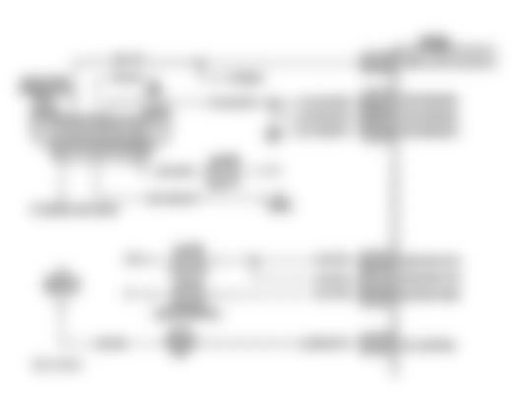
Isuzu Hombre S 1996 - Circuit Description
Powertrain Control Module (PCM) monitors system voltage on ignition feed circuit terminals to PCM. If voltage is less than calibrated value, DTC will set.
Conditions for setting this DTC are as follows:
- System voltage is less than 10 volts.
- Engine speed is greater than 1300 RPM.
- Fault is present for more than 4 minutes.
Isuzu Hombre S 1996 - Diagnostic Procedures
- Perform On-Board Diagnostic (OBD) System Check. After performing OBD system check, go to next step.
- Start engine. Increase engine speed to 1400 RPM. Load electrical system (turn on headlights, high blower, etc.). Using scan tool, check ignition voltage. If voltage is less than 10 volts, go to next step. If voltage is 10 volts or greater, go to step 8).
- Ensure engine speed is still at 1400 RPM. Using DVOM, measure voltage at battery. If voltage is greater than 12 volts, go to next step. If voltage is 12 volts or less, repair charging system as necessary.
- Turn ignition off. Disconnect PCM connectors. Turn ignition on, with engine off. Using DVOM, measure voltage between ground and ignition feed circuit No. 2 terminal at PCM connector. If voltage is greater than 10 volts, go to next step. If voltage is 10 volts or less, go to step 6).
- Check for poor connections at PCM harness connector terminals. Repair as necessary. After repair is completed, go to step 8). If connector terminals are okay, go to step 7).
- Repair poor connection in ignition feed circuit No. 2. After repair is completed, go to step 8).
- Replace PCM. Program replacement PCM using required equipment. After repair is completed, go to next step.
- Using scan tool, select CLEAR INFO or CLEAR DTCS function to clear DTCs. Start engine and allow it to idle. Ensure engine is at normal operating temperature. Operate vehicle within conditions required for setting this DTC. Select SPECIFIC DTC function then enter DTC P0562. If scan tool indicates TEST RAN AND PASSED, go to next step. If scan tool does not indicate TEST RAN AND PASSED, repeat step 2).
- If any other DTCs are set, diagnose DTCs as necessary. If no other DTCs are set, no problem is indicated at this time. See DIAGNOSTIC AIDS.
Isuzu Hombre S 1996 - Diagnostic Aids
If DTC sets when an accessory is operated, check for poor connection or excessive current draw.
Isuzu Hombre S 1996 - DTC P0563 - SYSTEM VOLTAGE HIGH
NOTE: For circuit reference, see Code P0562 schematic.
Isuzu Hombre S 1996 - Circuit Description
Powertrain Control Module (PCM) monitors system voltage on ignition feed circuit terminals to PCM. If voltage is greater than calibrated value, DTC will set.
Condition for setting this DTC is as follows:
- System voltage is greater than 17 volts.
Isuzu Hombre S 1996 - Diagnostic Procedures
- Perform On-Board Diagnostic (OBD) System Check. After performing OBD system check, go to next step.
- Turn all accessories off. Start engine. Increase engine speed to 1400 RPM. Using scan tool, check ignition voltage. If voltage is greater than 17 volts, go to next step. If voltage is 17 volts or less, go tostep 5).
- Increase engine speed to 2000 RPM. Using DVOM, measure voltage at battery. If voltage is less than 17 volts, go to next step. If voltage is 17 volts or greater, repair charging system as necessary.
- Replace PCM. Program replacement PCM using required equipment. After repair is completed, go to next step.
- Using scan tool, select CLEAR INFO or CLEAR DTCS function to clear DTCs. Start engine and allow it to idle. Ensure engine is at normal operating temperature. Operate vehicle within conditions required for setting this DTC. Select SPECIFIC DTC function then enter DTC P0563. If scan tool indicates TEST RAN AND PASSED, no problem is indicated at this time. See DIAGNOSTIC AIDS. If scan tool does not indicate TEST RAN AND PASSED, repeat step 2).
Isuzu Hombre S 1996 - Diagnostic Aids
If DTC sets when an accessory is operated, check for poor connection or excessive current draw.
Isuzu Hombre S 1996 - DTC P0600 - LOSS OF COMMUNICATION LINK Circuit Description
Powertrain Control Module (PCM) constantly receives information from various sensors, and controls systems that affect vehicle performance. PCM consists of 2 internal sides that communicate with each other. When communication between the 2 sides is lost, PCM cannot function properly and a DTC will set.
Condition for setting this DTC is as follows:
- PCM cannot communicate between the 2 sides.
Isuzu Hombre S 1996 - Diagnostic Procedures
- Perform On-Board Diagnostic (OBD) System Check. After performing OBD system check, go to next step.
- Replace PCM. Program replacement PCM using required equipment. After repair is completed, go to next step.
- Using scan tool, select CLEAR INFO or CLEAR DTCS function to clear DTCs. Start engine and allow it to idle. Ensure engine is at normal operating temperature. Operate vehicle within conditions required for setting this DTC. Select SPECIFIC DTC function then enter DTC P0600. If scan tool indicates TEST RAN AND PASSED, go to next step. If scan tool does not indicate TEST RAN AND PASSED, repeat step 2).
- If any other DTCs are set, diagnose DTCs as necessary. If no other DTCs are set, no problem is indicated at this time.
Isuzu Hombre S 1996 - DTC P0601 - PCM MEMORY Circuit Description
An Electronically Erasable Programmable Read Only (EEPROM) is used to contain the program information and calibrations required for engine, transmission and powertrain diagnostics operation. Powertrain Control Module (PCM) uses a value called a checksum for error detection of software. Checksum is a value that is equal to all numbers in software added together. PCM adds all values in the software and if that value does not equal the checksum value, a DTC will set.
Condition for setting this DTC is as follows:
- PCM detects more than 3 incorrect checksums.
Isuzu Hombre S 1996 - Diagnostic Procedures
- Perform On-Board Diagnostic (OBD) System Check. After performing OBD system check, go to next step.
- Replace PCM. Program replacement PCM using required equipment. After repair is completed, go to next step.
- Using scan tool, select CLEAR INFO or CLEAR DTCS function to clear DTCs. Start engine and allow it to idle. Ensure engine is at normal operating temperature. Operate vehicle within conditions required for setting this DTC. Select SPECIFIC DTC function then enter DTC P0601. If scan tool indicates TEST RAN AND PASSED, go to next step. If scan tool does not indicate TEST RAN AND PASSED, repeat step 2).
- If any other DTCs are set, diagnose DTCs as necessary. If no other DTCs are set, no problem is indicated at this time.
Isuzu Hombre S 1996 - DTC P0602 - PCM NOT PROGRAMMED Circuit Description
An Electronically Erasable Programmable Read Only (EEPROM) is used to contain the program information and calibrations required for engine, transmission and powertrain diagnostic operation. EEPROM program can be updated by reprogramming Powertrain Control Module (PCM).
Isuzu Hombre S 1996 - Diagnostic Procedures
- Perform On-Board Diagnostic (OBD) System Check. After performing OBD system check, go to next step.
- If PCM was just replaced, go to next step. If PCM was not just replaced, go to step 4).
- Program replacement PCM using required equipment. If DTC resets, attempt to reprogram PCM again (maximum of 3 times). If DTC still resets, go to next step. If DTC does not reset, go to step 5).
- Replace PCM. Program replacement PCM using required equipment. After repair is completed, go to next step.
- Using scan tool, select CLEAR INFO or CLEAR DTCS function to clear DTCs. Start engine and allow it to idle. Ensure engine is at normal operating temperature. Operate vehicle within conditions required for setting this DTC. Select SPECIFIC DTC function then enter DTC P0602. If scan tool indicates TEST RAN AND PASSED, go to next step. If scan tool does not indicate TEST RAN AND PASSED, repeat step 2).
- If any other DTCs are set, diagnose DTCs as necessary. If no other DTCs are set, no problem is indicated at this time.
Isuzu Hombre S 1996 - DTC P1133 - O2S INSUFFICIENT SWITCHING SENSOR 1
NOTE: For circuit reference, see Code P0131 schematic.
Isuzu Hombre S 1996 - Circuit Description
Powertrain Control Module (PCM) continuously monitors Oxygen Sensor 1 (O2S 1) activity for 100 seconds. During the monitor period, PCM counts number of times than O2S 1 switches from rich to lean and from lean to rich. If total number of switches is less than calibrated value, a DTC P1133 will set.
Conditions for setting this DTC are as follows:
- Number of lean to rich counts is less than 15 or rich to lean counts is less than 10.
- Engine speed is 1600-2600 RPM.
- TP sensor angle is 8-20 percent.
- No presence of Codes: P0106-P0108, P0112, P0113, P0117, P0118, P0121-P0123, P0300-P0304, P0506, P0507, P1441.
- Purge learn memory is greater than 191.
- Evaporative emission control system is commanded open for greater than 60 percent Pulse Width Modulated (PWM).
Isuzu Hombre S 1996 - Diagnostic Procedures
- Perform On-Board Diagnostic (OBD) System Check. After performing OBD system check, go to next step.
- If other DTCs are present, diagnose affected DTCs. If no other DTCs are present, go to next step.
- Start engine. Ensure engine is at normal operating temperature. Operate vehicle within the conditions required for setting this DTC. Using scan tester, monitor LEAN/RICH transition and note number of switches. Also, note number of RICH/LEAN transitions. If LEAN/RICH transitions are less than 15 and RICH/LEAN transitions are less than 10, go to next step. If LEAN/RICH transitions are 15 or greater and RICH/LEAN transitions are 10 or greater, see DIAGNOSTIC AIDS.
- Inspect the following:
- Check for proper O2S 1 installation.
- Check O2S 1 connector and wiring for corrosion or damage.
- Check O2S 1 ground circuit.
Repair as necessary. After repair is completed, go to step 9). If no problems were found, go to next step.
- Check exhaust manifold for leaks. Repair as necessary. After repair is completed, repeat step 3). If exhaust is okay, go to next step.
- Disconnect O2S 1 connector. Turn ignition on. Using scan tool, monitor O2S 1 voltage. If voltage is 407-509 mV, go to next step. If voltage is not 407-509 mV, go to step 10).
- Connect a jumper wire between ground and signal circuit terminal at O2S 1 harness connector. If voltage is less than 200 mV, go to next step. If voltage is 200 mV or greater, go to step 11).
- Replace oxygen sensor. Determine cause of sensor contamination, otherwise new sensor will be damaged. After repair is completed, go to step 17).
- Repair wiring or terminal as necessary. DO NOT attempt to repair damaged oxygen sensor connector or wiring. If damage is detected, replace oxygen sensor. After repair is completed, go to step 17).
- Repair short to ground in O2S 1 signal circuit. After repair is completed, go to step 17).
- Remove jumper wire. Measure voltage between ground and signal circuit at O2S 1 harness connector. If voltage is greater than 407 mV, go to next step. If voltage is 407 mV or less, go to step 13).
- Turn ignition off. Disconnect PCM connectors. Measure resistance between ground and O2S 1 ground circuit at PCM connector. If resistance is less than 5 ohms, go to step 14). If resistance is 5 ohms or greater, repair open in ground circuit. After repair is completed, go to step 17).
- Turn ignition off. Disconnect PCM connectors. Measure resistance of signal circuit between O2S 1 harness connector and PCM connector. If resistance is less than 5 ohms, go to step 15). If resistance is 5 ohms or greater, repair open in sensor signal circuit. After repair is completed, go to step 17).
- Check O2S 1 ground circuit terminal connection at PCM connector. Repair or replace terminal as necessary. If ground circuit terminal is okay, go to step 16). After repair is completed, go tostep 17).
- Check O2S 1 signal circuit terminal connection at PCM connector. Repair or replace terminal as necessary. After repair is completed, go to step 17). If ground circuit terminal is okay, go to next step.
- Replace PCM. Program replacement PCM using required equipment. After repair is completed, go to next step.
- Using scan tool, select CLEAR INFO or CLEAR DTCS function to clear DTCs. Start engine and allow it to idle. Ensure engine is at normal operating temperature. Operate vehicle within conditions required for setting this DTC. Select SPECIFIC DTC function then enter DTC P1133. If scan tool indicates TEST RAN AND PASSED, go to next step. If scan tool does not indicate TEST RAN AND PASSED, repeat step 2).
- If any other DTCs are set, diagnose DTCs as necessary. If no other DTCs are set, See DIAGNOSTIC AIDS.
Isuzu Hombre S 1996 - Diagnostic Aids
Check if fuel pressure is too high. PCM can compensate for some increase; however, if fuel pressure is too high, DTC will set. Check for leaking injector(s) or faulty fuel pressure regulator. See SYSTEM/COMPONENT TESTS article.
Check EVAP system for fuel saturation. Disconnect MAP sensor harness connector and see if rich condition is corrected. If rich condition is corrected, check for faulty MAP sensor. Check for oxygen sensor silicone contamination. Check TP sensor. See SYSTEM/COMPONENT TESTS article.
Isuzu Hombre S 1996 - DTC P1171 - FUEL SYSTEM LEAN DURING ACCELERATION Circuit Description
Powertrain Control Module (PCM) internal circuitry can identify if vehicle fuel system is capable of supplying adequate amounts of fuel during heavy acceleration (power enrichment). When a power enrichment mode of operation is requested, PCM will allow additional fuel to be provided to the engine. If PCM does not detect a rich exhaust, a DTC P1171 will set.
Conditions for setting this DTC are as follows:
- O2S 1 voltage is less than 300 mV for 5 seconds.
- O2S 1 is operating in closed loop.
- No presence of Codes: P0131-P0134.
- Fuel injector BPW is more than zero.
- Fuel delivery system is in power enrichment mode.
Isuzu Hombre S 1996 - Diagnostic Procedures
- Perform On-Board Diagnostic (OBD) System Check. After performing OBD system check, go to next step.
- If other DTCs are present, diagnose affected DTC(s). If no other DTCs are present, go to next step.
- Check fuel level in tank. Add fuel as necessary. If fuel level was low (almost empty), go to step 5). If fuel level was okay, go to next step.
- Start engine. Ensure engine coolant temperature is 167-203?F (75-95?C). Raise engine speed to 1200 RPM. Using scan tool, observe O2S 1 voltage. Voltage should vary within a range of 100-900 mV. Occasionally voltage should increase to more than 447 mV (during power enrichment mode). If voltage is as specified, go to BASIC FUEL SYSTEM CHECKS (A-7) in appropriate BASIC TESTING article. If voltage is not as specified, go to DTC P0134.
- Using scan tool, select CLEAR INFO or CLEAR DTCS function to clear DTCs. Start engine and allow it to idle. Ensure engine is at normal operating temperature. Operate vehicle within conditions required for setting this DTC. Select SPECIFIC DTC function then enter DTC P1171. If scan tool indicates TEST RAN AND PASSED, go to next step. If scan tool does not indicate TEST RAN AND PASSED, repeat step 2).
- If any other DTCs are set, diagnose DTCs as necessary. If no other DTCs are set, no problem is indicated at this time. See DIAGNOSTIC AIDS.
Isuzu Hombre S 1996 - Diagnostic Aids
A restricted fuel filter can supply adequate amounts of fuel at idle, but may not be able to supply enough fuel during heavy acceleration. Water or alcohol in fuel may cause low O2S 1 voltage during acceleration. Check for defective or plugged fuel injectors.
Isuzu Hombre S 1996 - DTC P1380 - ABS DTC ROUGH ROAD DATA UNSTABLE (MAN TRANSAXLE) Circuit Description
PCM detects engine misfire by detecting variations in crankshaft deceleration between firing strokes. For accurate detection of engine misfire, PCM must be able to distinguish between crankshaft deceleration caused by actual misfire or deceleration caused by rough road conditions.
The ABS system can detect if vehicle is on a rough road based on wheel acceleration/deceleration data supplied by the wheel speed sensors. If ABS system detects rough road above a predetermined threshold, this information is sent to the PCM via the serial data (UART). PCM can then take the rough road into account when calculating misfire. Even if the ABS is malfunctioning and cannot detect rough roads, the misfire diagnostic will continue to run. However, if a misfire DTC is set, this additional DTC P1380 will also set indicating that rough road data was not available during the misfire calculation due to ABS system malfunction.
Conditions for setting this DTC are as follows:
- Vehicle speed is more than one MPH.
- Map is less than 99 kPa.
- DTC P0300-P0304 has been set.
- Engine speed is less than 3400 RPM.
- An ABS DTC is set.
Isuzu Hombre S 1996 - Diagnostic Procedures
- Perform On-Board Diagnostic (OBD) System Check. After performing OBD system check, go to next step.
- Turn ignition on, with engine off. Using scan tool, check for ABS DTCs. If any ABS DTCs are set, go to next step. If no ABS DTCs are set, go to step 4).
- Repair ABS system as necessary. See ANTI-LOCK BRAKES article.
- Turn ignition on, with engine off. Using scan tool, review FREEZE FRAME data and note parameters. Start engine and operate vehicle within conditions required for setting this DTC, and as close to conditions recorded in FREEZE FRAME as possible. If misfire DTC set, go to next step. If misfire DTC did not set, go to step 9).
- If DTC P1380 also set, go to next step. If DTC P1380 did not set, go to step 7).
- If ABS DTC is also set, go to step 3). If ABS DTC is not set, go tostep 8).
- Repair condition causing misfire as necessary. After repair is completed, go to step 9).
- Replace PCM. Program replacement PCM using required equipment. After repair is completed, go to next step.
- Using scan tool, select CLEAR INFO or CLEAR DTCS function to clear DTCs. Start engine and allow it to idle. Ensure engine is at normal operating temperature. Operate vehicle within conditions required for setting this DTC. Select SPECIFIC DTC function then enter DTC P1380. If scan tool indicates TEST RAN AND PASSED, go to next step. If scan tool does not indicate TEST RAN AND PASSED, repeat step 2).
- If any other DTCs are set, diagnose DTCs as necessary. If no other DTCs are set, no problem is indicated at this time.
Isuzu Hombre S 1996 - Diagnostic Aids
Setting of this DTC indicates that a misfire was detected and that the PCM could not determine if fault was a true misfire or due to operating vehicle on a rough surface. A misfire can be a true misfire with or without setting this DTC. Check Electronic Brake Control Module (EBCM) for poor connections at serial data (UART) terminals.
Isuzu Hombre S 1996 - DTC P1381 - MISFIRE DETECTED - NO EBCM/PCM SERIAL DATA (MANUAL TRANSAXLE) Circuit Description
PCM detects engine misfire by detecting variations in crankshaft deceleration between firing strokes. For accurate detection of engine misfire, PCM must be able to distinguish between crankshaft deceleration caused by actual misfire or deceleration caused by rough road conditions.
The ABS system can detect if vehicle is on a rough road based on wheel acceleration/deceleration data supplied by the wheel speed sensors. If ABS system detects rough road above a predetermined threshold, this information is sent to the PCM via the serial data (UART). PCM can then take the rough road into account when calculating misfire. Even if the ABS is malfunctioning and cannot detect rough roads, the misfire diagnostic will continue to run. However, if a misfire DTC is set, this additional DTC P1380 will also set indicating that rough road data was not available during the misfire calculation due to ABS system malfunction.
Conditions for setting this DTC are as follows:
- Vehicle speed is greater than one MPH.
- Map is less than 99.7 kPa.
- Map is less than 99.7 kPa.
- Engine speed is less than 3406 RPM.
- DTC P0300-P0304 have been set.
Isuzu Hombre S 1996 - Diagnostic Procedures
- Perform On-Board Diagnostic (OBD) System Check. After performing OBD system check, go to next step.
- Turn ignition on, with engine off. Using scan tool, attempt to display ABS data. If ABS data can be displayed, go to next step. If ABS data cannot be displayed, go to step 4).
- Using scan tool, select CLEAR INFO or CLEAR DTCS function to clear DTCs. Review FREEZE FRAME data and note parameters. Start engine and operate vehicle within conditions required for setting this DTC, and as close to conditions recorded in FREEZE FRAME as possible. If a misfire DTC set, go to step 5). If a misfire DTC did not set, go to step 9).
- Repair condition causing ABS data not to be displayed. See appropriate ANTI-LOCK BRAKES article. After repair is completed, go to step 3).
- If DTC P1381 also set, go to next step. If DTC P1381 did not set, go to step 7).
- If ABS data can be displayed, go to step 8). If ABS data cannot be displayed, go to step 4).
- Repair condition causing misfire as necessary. After repair is completed, go to step 9).
- Replace PCM. Program replacement PCM using required equipment. After repair is completed, go to next step.
- Using scan tool, select CLEAR INFO or CLEAR DTCS function to clear DTCs. Start engine and allow it to idle. Ensure engine is at normal operating temperature. Operate vehicle within conditions required for setting this DTC. Select SPECIFIC DTC function then enter DTC P1381. If scan tool indicates TEST RAN AND PASSED, go to next step. If scan tool does not indicate TEST RAN AND PASSED, repeat step 2).
- If any other DTCs are set, diagnose DTCs as necessary. If no other DTCs are set, no problem is indicated at this time.
Isuzu Hombre S 1996 - Diagnostic Aids
Setting of this DTC indicates that a misfire was detected and that the PCM could not determine if fault was a true misfire or due to operating vehicle on a rough surface. A misfire can be a true misfire with or without setting this DTC. Check Electronic Brake Control Module (EBCM) for poor connections at serial data (UART) terminals.
Isuzu Hombre S 1996 - DTC P1406 - EGR VALVE PINTLE POSITION CIRCUIT
NOTE: For circuit reference, see Code P0401 schematic.
Isuzu Hombre S 1996 - Circuit Description
A linear Exhaust Gas Recirculation (EGR) valve is used on this system. Powertrain Control Module (PCM) commands EGR valve to operate when necessary by controlling a ground signal through PCM. This can be monitored on a scan tool by selecting DESIRED EGR POSITION function. Ignition voltage is supplied to EGR valve thorough a fuse. PCM monitors results of its command through a feedback signal. Feedback signal is the actual position of the EGR pintle. This feedback signal can also be monitored on a scan tool by selecting ACTUAL EGR POSITION function. The ACTUAL EGR POSITION should always be near the commanded or DESIRED EGR POSITION.
Conditions for setting this DTC are as follows:
- No presence of Codes: P0106-P0108, P0112, P0113, P0117, P0118, P0121-P0123, P0125, P0200, P0300-P0304, P0335, P0440, P0442, P0446, P0502, P0503, P0506, P0507, P1441.
With EGR commanded off.
- Actual EGR position is greater than 3 percent for 25 seconds.
- ACTUAL EGR POSITION differs from DESIRED EGR POSITION by greater than 6 percent for 20 seconds.
With EGR commanded on.
- ACTUAL EGR POSITION differs from DESIRED EGR POSITION by greater than 9 percent for 18 seconds when DESIRED EGR POSITION is less than 99 percent.
- ACTUAL EGR POSITION differs from DESIRED EGR POSITION by greater than 20 percent for 18 seconds when DESIRED EGR POSITION is greater than 99 percent.
Isuzu Hombre S 1996 - Diagnostic Procedures
- Perform On-Board Diagnostic (OBD) System Check. After performing OBD system check, go to next step.
- Turn ignition on, with engine off. Using scan tool, command EGR valve to 25, 50, 75 and 100 percent. If ACTUAL EGR POSITION follows the DESIRED EGR POSITION, go to step 15). If ACTUAL EGR POSITION does not follow the DESIRED EGR POSITION, go to next step.
- Disconnect EGR valve connector. With test light connected to ground, probe ignition feed circuit terminal at EGR valve harness connector. If test light is off, go to step 5). If test light is on, go to next step.
- With test light connected to positive battery terminal, probe control circuit terminal at EGR valve harness connector. Using scan tool, command EGR valve open to 25, 50, 75 and 100 percent. If test light is on dim, then gets brighter or flashes when commanded percentage is increased, go to step 6). If test light does not function as specified, go to step 7).
- Repair open in EGR valve ignition feed circuit. After repair is completed, go to step 15).
- Using DVOM, measure voltage between ground and 5-volt reference circuit terminal at EGR valve harness connector. If voltage is 5 volts, go to step 8). If voltage is not 5 volts, go to step 9).
- Check for an open or short in EGR valve control circuit. Repair as necessary. After repair is completed, go to step 15). If circuit is okay, go to step 14).
- Using DVOM, measure voltage between positive battery terminal and sensor ground circuit terminal at EGR valve harness connector. If battery voltage is present, go to step 10). If battery voltage is not present, go to step 11).
- Check for an open or short in EGR valve 5-volt reference circuit. Repair as necessary. After repair is completed, go to step 15). If circuit is okay, go to step 14).
- Connect a jumper wire between 5-volt reference and signal circuit terminals at EGR valve harness connector. If ACTUAL EGR POSITION displays 100 percent, go to step 12). If ACTUAL EGR POSITION does not display 100 percent, go to step 13).
- Check for an open in EGR valve 5-volt reference circuit. Repair as necessary. After repair is completed, go to step 15). If circuit is okay, go to step 14).
- Replace EGR valve. After repair is completed, go to step 15).
- Check for an open or short in EGR valve signal circuit. Repair as necessary. After repair is completed, go to step 15). If circuit is okay, go to next step.
- Replace PCM. Program replacement PCM using required equipment. After repair is completed, go to next step.
- Using scan tool, select CLEAR INFO or CLEAR DTCS function to clear DTCs. Start engine and allow it to idle. Ensure engine is at normal operating temperature. Operate vehicle within conditions required for setting this DTC. Select SPECIFIC DTC function then enter DTC P1406. If scan tool indicates TEST RAN AND PASSED, go to next step. If scan tool does not indicate TEST RAN AND PASSED, repeat step 2).
- If any other DTCs are set, diagnose DTCs as necessary. If no other DTCs are set, no problem is indicated at this time. See DIAGNOSTIC AIDS.
Isuzu Hombre S 1996 - Diagnostic Aids
Moisture in exhaust system may cause EGR valve to freeze or stick in colder weather. After vehicle is brought into a warm shop for repairs, EGR valve warms and the problem goes away. By watching ACTUAL EGR POSITION and DESIRED EGR POSITION on a cold vehicle with a scan tool. View FREEZE FRAME data to determine if DTC set when vehicle was cold by viewing ENGINE COOLANT TEMPERATURE and INTAKE AIR TEMPERATURE.
Isuzu Hombre S 1996 - DTC P1441 - EVAP SYSTEM FLOW DURING NON-PURGE
NOTE: For circuit reference, see Code P0440 schematic.
Isuzu Hombre S 1996 - Circuit Description
Evaporative Emission (EVAP) system is checked by applying vacuum to EVAP system and monitoring vacuum decay. Powertrain Control Module (PCM) monitors vacuum level by means of fuel tank vacuum sensor input. At a predetermined time, EVAP purge solenoid and EVAP vent solenoid are turned on. This allows engine vacuum to draw a small vacuum on entire EVAP system.
Conditions for setting this DTC are as follows:
- Intake air temperature is more than 32?F (0?C).
- No presence of Codes: P0106-P0108, P0112, P0113, P0117, P0118, P0121-P0123, P0125, P0131-P0134, P1133.
- Fuel tank level is 15-85 percent.
- A continuous purge flow condition is detected during diagnostic test.
Isuzu Hombre S 1996 - Diagnostic Procedures
- Perform On-Board Diagnostic (OBD) System Check. See ON-BOARD DIAGNOSTIC (OBD) SYSTEM CHECK. After performing OBD system check, go to next step.
- Turn ignition on, with engine off. Using scan tool, command EVAP canister purge valve and EVAP vent solenoids on and off. If purge valve and vent solenoids click, go to next step. If purge valve and/or vent solenoid dose not click, repair wiring or replace purge valve and/or vent solenoid as necessary.
- Remove fuel cap. Using scan tool, observe FUEL TANK VACUUM PRESSURE. If pressure is zero in. H2O, go to step 6). If pressure is more than zero in. H2O, go to next step.
- If battery has been disconnected, check fuel tank pressure sensor. See SYSTEM/COMPONENT TESTS article. Replace fuel tank pressure sensor or repair related wiring as necessary. If battery has not been disconnected, go to next step.
- Reinstall fuel cap. Using scan tool, command EVAP vent solenoid on (closed). Zero EVAP pressure and vacuum gauges on EVAP Pressure/Purge Cart (J-41413). Connect EVAP pressure/purge cart to EVAP service port. Attempt to pressurize EVAP system to 5 in. H2O. Monitor pressure using gauge on EVAP pressure/purge cart. If pressure can be achieved, go to next step. If pressure cannot be achieved, go to step 8).
- Maintain EVAP system pressure at 5 in. H2O. Using scan tool, observe FUEL TANK VACUUM PRESSURE. If pressure reading is 4-6 in. H2O, go to next step. If pressure reading is not 4-6 in. H2O, check fuel tank pressure sensor. See the appropriate SYSTEM/COMPONENT TESTS article. Replace fuel tank pressure sensor or repair related wiring as necessary.
- Disconnect vacuum hose at EVAP canister purge valve (from throttle body). Connect a vacuum pump to EVAP canister purge valve vacuum source fitting. Apply 15 in. Hg. Using scan tool, command EVAP canister purge valve on. If vacuum is released, go to step 10). If vacuum holds, go to next step.
- Check EVAP canister purge valve vacuum hoses for correct routing. If vacuum hoses are routed incorrectly, go to step 11). If vacuum hoses are routed correctly, see DIAGNOSTIC AIDS. If vacuum hoses are routed correctly, go to step 11).
- Replace EVAP canister purge valve. After repair is completed, go to step 12).
- Correct vacuum hose routing. After repair is completed, go to next step.
- Start engine. Remove fuel cap. Using scan tool, command EVAP vent solenoid on (closed) and EVAP canister vent valve off (zero percent). Reinstall fuel cap. While monitoring FUEL TANK VACUUM PRESSURE on scan tool, raise engine speed to 2500 RPM. If pressure is zero in. H2O, system is functioning properly. If pressure is more than zero in. H2O, repeat step 2).
Isuzu Hombre S 1996 - Diagnostic Aids
Check for incorrect vacuum hose routing to EVAP canister purge valve. Check PCM connector for poor terminal connections. Check for damaged EVAP related wiring harness.
Isuzu Hombre S 1996 - SUMMARY
If no hard fault codes are present, driveability symptoms exist or intermittent codes exist, proceed to TESTS W/O CODES article for diagnosis by symptom (i.e., ROUGH IDLE, NO START, etc.) or intermittent diagnostic procedures.