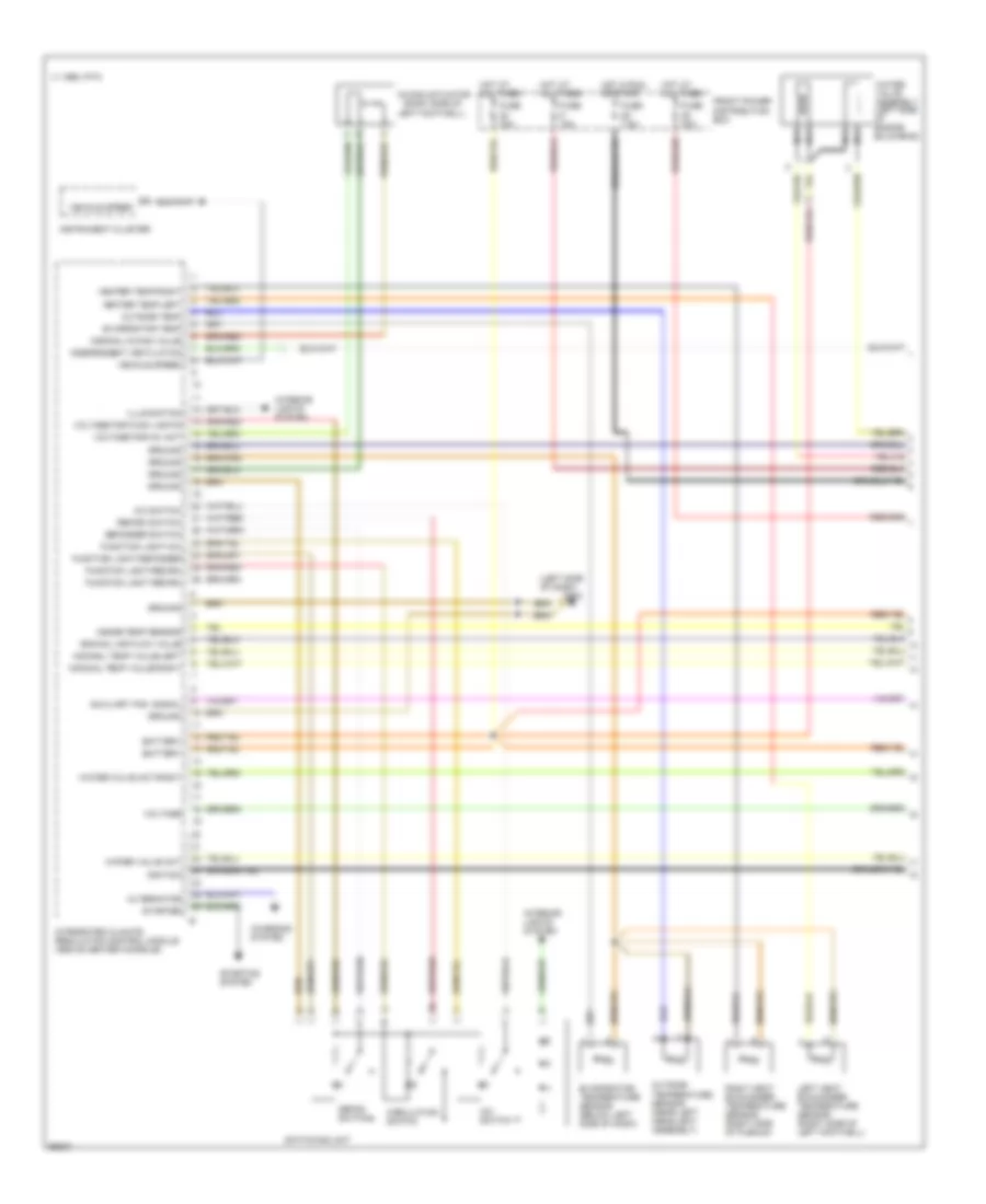
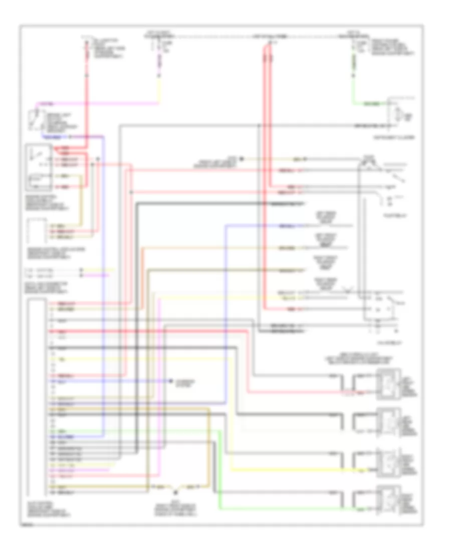
AIR CONDITIONING
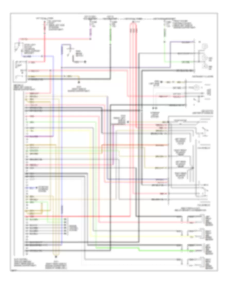
A/C Wiring Diagram (1 of 3) for BMW 535i 1993
 https://portal-diagnostov.com/license.html
Automotive Electricians Portal FZCO
Automotive Electricians Portal FZCO
https://portal-diagnostov.com/license.html
https://portal-diagnostov.com/license.html
Automotive Electricians Portal FZCO
Automotive Electricians Portal FZCO
List of elements for A/C Wiring Diagram (1 of 3) for BMW 535i 1993:
- (left side of dash)
- (right side of
- A/c switch
- Alternator
- Auxiliary fan signal
- Battery
- C 1995 vftc
- Charging system
- Circulation switch
- Defog switch
- Defogger switch
- Evaporator temp
- Evaporator temperature sensor (below left side of dash)
- Front power distribution box
- Function light recirc
- Function light-a/c
- Function light-defogger
- Function light-recirc
- Fuse 15a
- Fuse 30a
- Fuse 7.5a
- G202
- Ground
- Heater temp-left
- Heater temp-right
- Hot at all times
- Hot at all times mixing actuator
- Hot in run or start
- Ignition
- Illumination
- Independent ventilation
- Inside temp sensor
- Instrument cluster
- Integrated climate regulation control module (above center console)
- Interior lights system
- Left footwell)
- Left heat exchanger temperature sensor (right side of left footwell)
- Nca
- Nominal air flow value
- Nominal mixing value
- Nominal temp value-left
- Nominal temp value-right
- Outside temp
- Outside temperature sensor (near left headlight assembly)
- Recirc switch
- Right heat exchanger temperature sensor (right side of plenum)
- Starter
- Starting system
- Switching unit
- Vehicle speed
- Voltage
- Voltage for func lights
- Voltage for mix act
- Water valve act
- Water valve act-right
- Water valve assembly (left side of engine bulkhead)
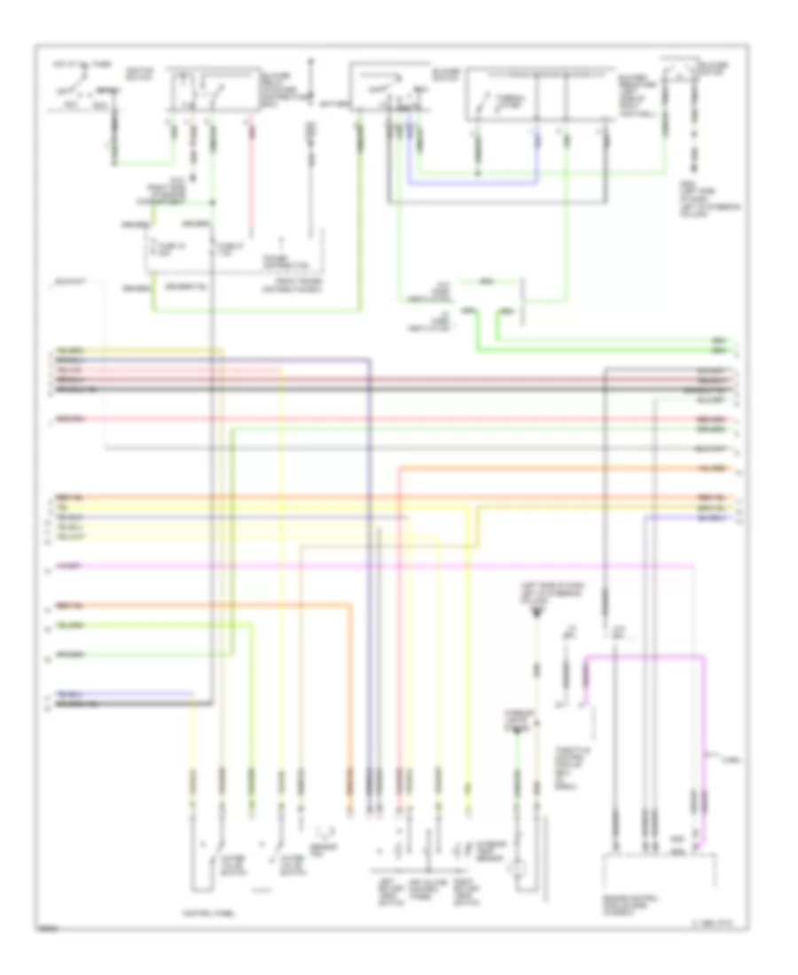
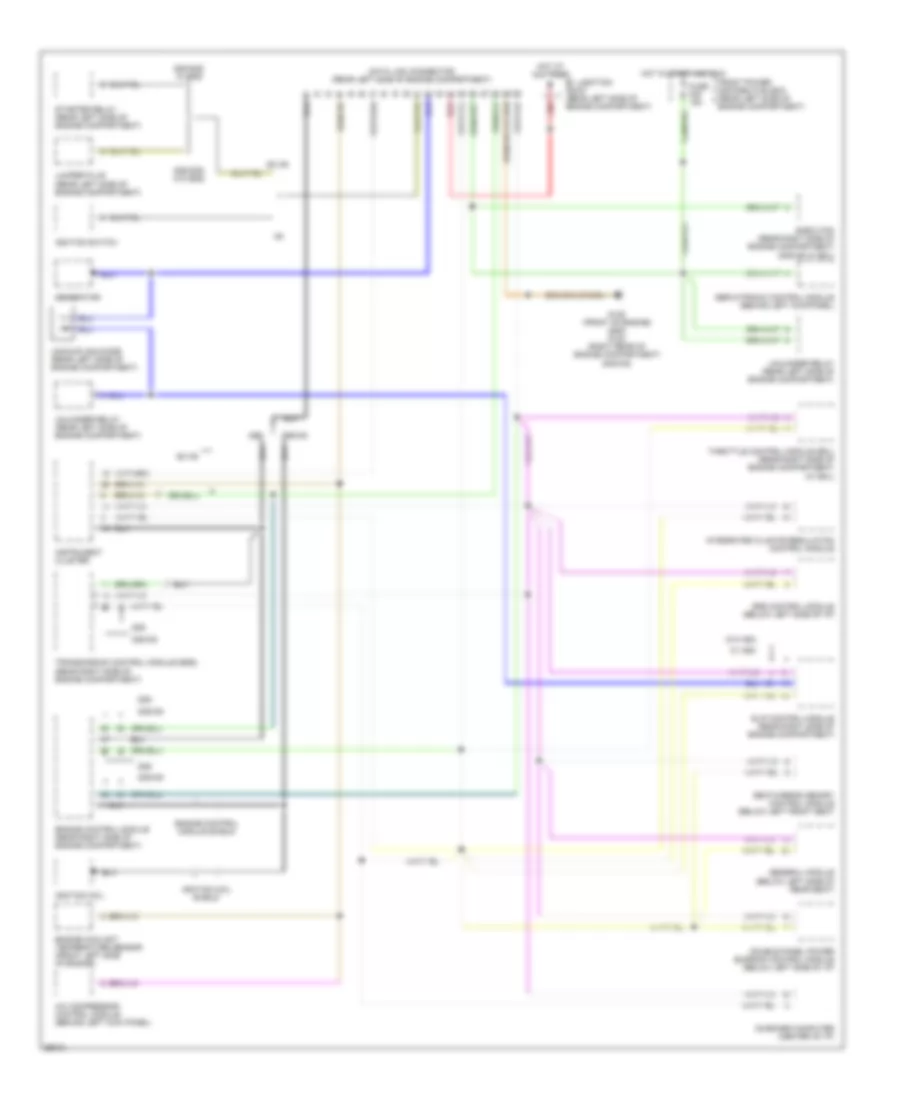
A/C Wiring Diagram (2 of 3) for BMW 535i 1993
 https://portal-diagnostov.com/license.html
Automotive Electricians Portal FZCO
Automotive Electricians Portal FZCO
https://portal-diagnostov.com/license.html
https://portal-diagnostov.com/license.html
Automotive Electricians Portal FZCO
Automotive Electricians Portal FZCOList of elements for A/C Wiring Diagram (2 of 3) for BMW 535i 1993:
- (525)
- (535)
- (left side of dash, left of steering column)
- Acc
- Air volume control wheel
- Battery
- Blower motor
- Blower relay (in power distribution box)
- Blower resistors (left side of right footwell)
- Blower switch
- C 1995 vftc
- Control panel
- Engine control module (dme) (in e-box)
- Front power distribution box
- Fuse 19 30a
- Fuse 27 7.5a
- G101 (right side of engine compartment
- G202
- G202 (left side
- Hot at all times
- Ignition switch
- Interior lights system
- Interior temp sensor
- Left of steering column)
- Left rotary temp switch
- Max
- Nca
- Of dash,
- Off
- Power distribution
- Red
- Right rotary temp switch
- Run
- Sensor fan
- Start
- Thermal limiter
- Throttle control module (eml) (in e-box)
- W/ eml
- W/ park ventilation
- W/eml
- W/o eml
- W/o park ventilation
- Water valve switch
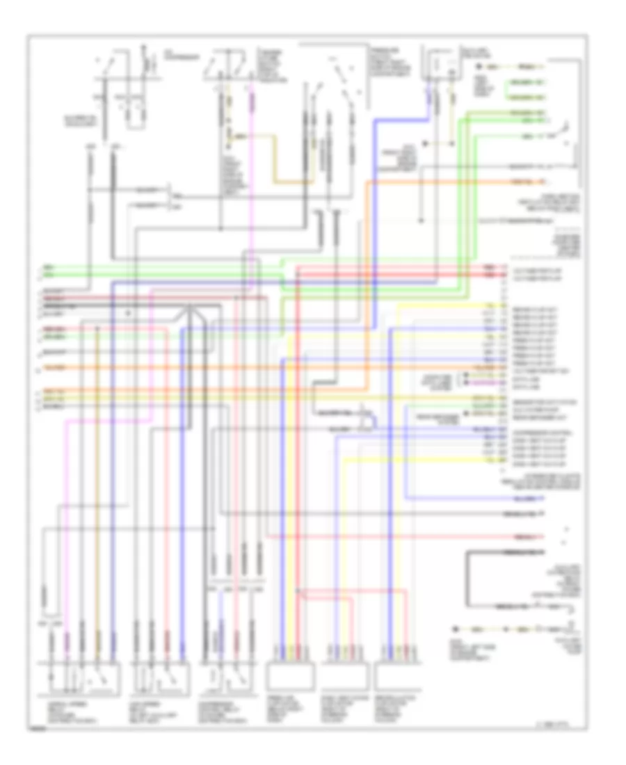
A/C Wiring Diagram (3 of 3) for BMW 535i 1993
 https://portal-diagnostov.com/license.html
Automotive Electricians Portal FZCO
Automotive Electricians Portal FZCO
https://portal-diagnostov.com/license.html
https://portal-diagnostov.com/license.html
Automotive Electricians Portal FZCO
Automotive Electricians Portal FZCOList of elements for A/C Wiring Diagram (3 of 3) for BMW 535i 1993:
- (below right seat)
- A/c compressor
- Aux water pump
- Auxiliary fan motor
- Auxiliary water pump
- Auxiliary water pump relay (in front power distribution box)
- C 1995 vftc
- Compartment)
- Compressor control
- Compressor control relay (in power distribution box)
- Computer data lines system
- Dash vent mix flap
- Dash vent mixing flap motor (right of steering column)
- Data line
- Fresh air flap motor (below right side of dash)
- Fresh flap act
- G100 (front left side of engine compartment)
- G101 (front right side of engine compart- ment)
- G101 (front right side of engine compartment)
- G202 (left side of dash)
- High speed relay (in left auxiliary relay box)
- Integrated climate regulation control module (above center console)
- Nca
- Normal speed relay (in power distribution box)
- On-board computer (center of dash)
- Park heating/ ventilation relay box
- Pressure
- Rear defogger act
- Rear defogger system
- Recirc flap act
- Recirculation flap motor (right of steering column)
- Red
- Sensor for activation
- Switch (front right side of engine
- Temper- ature switch (right top of radiator)
- Voltage for flap
- Voltage for rot sw
ANTI-LOCK BRAKES
Anti-lock Brake Wiring Diagrams, with Traction Control for BMW 535i 1993
 https://portal-diagnostov.com/license.html
Automotive Electricians Portal FZCO
Automotive Electricians Portal FZCO
https://portal-diagnostov.com/license.html
https://portal-diagnostov.com/license.html
Automotive Electricians Portal FZCO
Automotive Electricians Portal FZCOList of elements for Anti-lock Brake Wiring Diagrams, with Traction Control for BMW 535i 1993:
- Abs hydraulic init (below brake fluid reservoir)
- Abs ind
- Abs relay (rear left side of engine compartment)
- Asc ind
- Asc switch (center of console)
- B+ junction point (rear left side of engine compartment)
- Engine control system
- Front power distribution box (rear left side of engine compartment)
- Fuse f1 15a
- Fuse f17 7.5a
- Fuse f29 7.5a
- G100 (front left side of engine compartment)
- G101 (right front side of engine compartment ahead of wheelwell)
- G101 (right side of engine compartment)
- G202 (left side of i/p)
- Hot at all times
- Hot in accy, run or start
- Hot in run and start
- Hot in run or start
- Instrument cluster
- Interior lights system
- Left front abs speed sensor
- Left front solenoid valve
- Left rear abs speed sensor
- Left rear solenoid valve
- Nca
- Park brake switch
- Pump motor
- Red
- Right front abs speed sensor
- Right front solenoid valve
- Right rear abs speed sensor
- Right rear solenoid valve
- Slip control module (abs/asc) (right rear side of engine compartment)
- Solid state
- Starting/ charging system
- Stop light switch (on brake pedal support bracket)
- Valve relay
Anti-lock Brake Wiring Diagrams, without Traction Control for BMW 535i 1993
 https://portal-diagnostov.com/license.html
Automotive Electricians Portal FZCO
Automotive Electricians Portal FZCO
https://portal-diagnostov.com/license.html
https://portal-diagnostov.com/license.html
Automotive Electricians Portal FZCO
Automotive Electricians Portal FZCOList of elements for Anti-lock Brake Wiring Diagrams, without Traction Control for BMW 535i 1993:
- 87a
- Abs hydraulic unit (left side of engine compartment below brake fluid reservoir)
- Abs ind
- B+ junction point (rear left side of engine compartment)
- Brake light switch (on brake pedal support bracket)
- Charging system
- Data link connector (rear left side of engine compartment)
- Engine control module (dme) (rear right side of engine compartment)
- Engine control module relay (rear right side of engine compartment)
- Front power distribution box (rear left side of engine compartment)
- Fuse f1 15a
- Fuse f17 7.5a
- G100 (front left side of engine compartment)
- G101 (right front side of engine compartment ahead of wheelwell)
- Hot at all times
- Hot in accy run and start
- Hot in run and start
- Instrument cluster
- Left front abs speed sensor
- Left front solenoid valve
- Left rear abs speed sensor
- Left rear solenoid valve
- Nca
- Pump motor
- Pump relay
- Red
- Right front abs speed sensor
- Right front solenoid valve
- Right rear abs speed sensor
- Right rear solenoid valve
- Slip control module (abs) (rear right side of engine compartment)
- Valve relay
COMPUTER DATA LINES
Data Link Connector Wiring Diagram for BMW 535i 1993
 https://portal-diagnostov.com/license.html
Automotive Electricians Portal FZCO
Automotive Electricians Portal FZCO
https://portal-diagnostov.com/license.html
https://portal-diagnostov.com/license.html
Automotive Electricians Portal FZCO
Automotive Electricians Portal FZCOList of elements for Data Link Connector Wiring Diagram for BMW 535i 1993:
- 525i
- 525i/535i w/ egs
- 525i/535i w/o egs
- 535i/m5
- A/c compressor control module (behind left kick panel)
- B+ junction point (rear left side of engine compartment)
- Data link connector (rear left side of engine compartment)
- Double panel power sunroof control module (below left side of i/p)
- E-box fan (rear right side of engine compartment) (535i/m5 w/ eml)
- Engine control module (rear right side of engine compartment)
- Engine control module shield
- Engine coolant temperature sensor (front left side of engine)
- Ex m5
- Front power distribution box (rear left side of engine compartment)
- Fuse f28 15a
- G125 (front of engine) (525i) g123 (right rear of engine compartment) (535i/m5)
- General module (below left side of rear seat)
- Generator
- Hot at all times
- Hot in start and run
- Ignition coil
- Ignition coil shield
- Ignition switch
- Instrument cluster
- Integrated climate regulation control module
- Jumper plug (rear left side of engine compartment)
- On-board computer (center of i/p)
- Red
- Seat/mirror memory control module (below left front seat
- Servotronic control module (behind left kickpanel)
- Slip control module (rear right side of engine compartment)
- Srs control module (below left side of i/p)
- Starter relay (rear left side of engine compartment)
- Throttle control module (eml) (rear right side of engine compartment) (w/ eml)
- Transmission control module (egs) (rear right side of engine compartment)
- Uncoupling diode (rear left side of engine compartment)
- Unloader relay (rear left side of engine compartment)
- W/ asc
- W/o asc
COOLING FAN
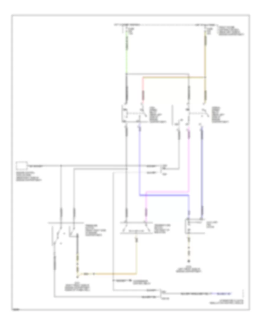
Auxiliary Cooling Fan Wiring Diagram for BMW 535i 1993
 https://portal-diagnostov.com/license.html
Automotive Electricians Portal FZCO
Automotive Electricians Portal FZCO
https://portal-diagnostov.com/license.html
https://portal-diagnostov.com/license.html
Automotive Electricians Portal FZCO
Automotive Electricians Portal FZCOList of elements for Auxiliary Cooling Fan Wiring Diagram for BMW 535i 1993:
- 525i
- 535i/ m5
- 535i/m5
- 86b
- Auxiliary fan motor
- Compressor control relay
- Engine control module (dme) (rear right side of engine compartment)
- Front power distribution box (rear left side of engine compartment)
- Fuse f25 30a
- Fuse f29 7.5a
- G100 (left front side of engine compartment)
- G101 (right front side of engine compartment ahead of wheelwell)
- High speed relay (rear left side of engine compartment)
- Hot at all times
- Hot in start and run
- Integrated climate regulation control module
- Normal speed relay (rear left side of engine compartment)
- Pressure switch (front right side of engine compartment)
- Temperature switch (top right of radiator)
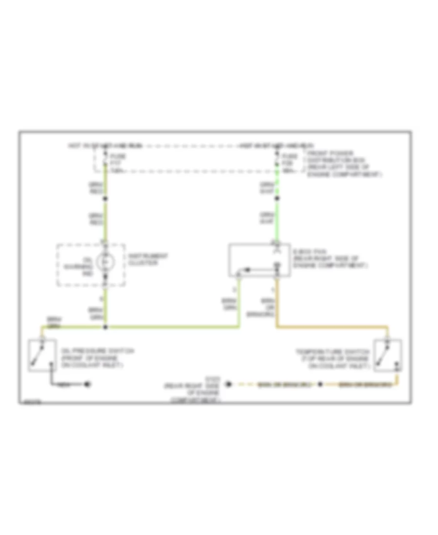
Electrical Box Fan Wiring Diagram for BMW 535i 1993
 https://portal-diagnostov.com/license.html
Automotive Electricians Portal FZCO
Automotive Electricians Portal FZCO
https://portal-diagnostov.com/license.html
https://portal-diagnostov.com/license.html
Automotive Electricians Portal FZCO
Automotive Electricians Portal FZCOList of elements for Electrical Box Fan Wiring Diagram for BMW 535i 1993:
- E-box fan (rear right side of engine compartment)
- Front power distribution box (rear left side of engine compartment)
- Fuse f17 7.5a
- Fuse f28 15a
- G123 (rear right side of engine compartment)
- Hot in start and run
- Instrument cluster
- Nca
- Oil pressure switch (front of engine on coolant inlet)
- Oil warning ind
- Temperature switch (top rear of engine on coolant inlet)
CRUISE CONTROL
Cruise Control Wiring Diagram for BMW 535i 1993
 https://portal-diagnostov.com/license.html
Automotive Electricians Portal FZCO
Automotive Electricians Portal FZCO
https://portal-diagnostov.com/license.html
https://portal-diagnostov.com/license.html
Automotive Electricians Portal FZCO
Automotive Electricians Portal FZCOList of elements for Cruise Control Wiring Diagram for BMW 535i 1993:
- (front of gear shift selector)
- Automatic transmission range switch
- Brake light switch (on brake pedal)
- Check control module
- Clutch switch (clutch pedal support bracket)
- Cruise control actuator (front left side of engine comp.)
- Cruise control module (left front of i/p)
- Cruise control switch
- Decelerate/ set
- Electronic *
- Exterior lights system
- Front power distribution box (rear left side of engine comp.)
- Fuse f1 15a
- Fuse f17 7.5a
- G101 (right side
- G202 (left
- Hot in acc, run and start
- Hot in run and start
- Instrument cluster
- Nca
- Normal
- Of engine comp.)
- Off
- Resume
- Set accelerate/
- Side of i/p)
- Transmission module
- Transmission system
- W/ egs *
- W/o egs
- X19
- X502
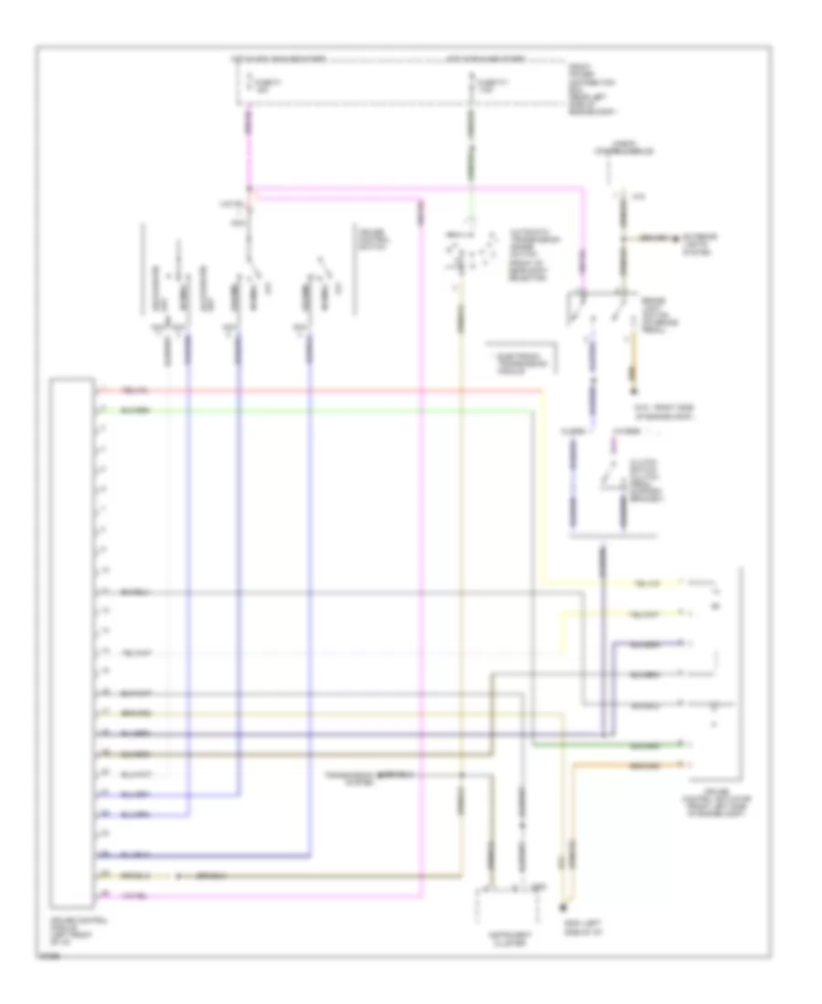
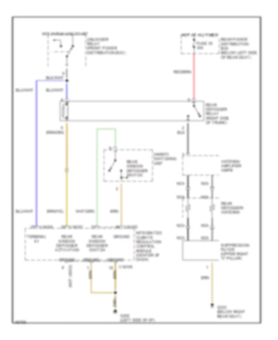
DEFOGGERS
Defogger Wiring Diagram for BMW 535i 1993
 https://portal-diagnostov.com/license.html
Automotive Electricians Portal FZCO
Automotive Electricians Portal FZCO
https://portal-diagnostov.com/license.html
https://portal-diagnostov.com/license.html
Automotive Electricians Portal FZCO
Automotive Electricians Portal FZCOList of elements for Defogger Wiring Diagram for BMW 535i 1993:
- (not used)
- Antenna amplifier am/fm
- Fuse 35 30a
- G202 (left side of i/p)
- G303 (below right rear seat)
- Ground
- Hot at all times
- Hot in run and start
- Ihkr/f3 switching unit
- Integrated climate regulation control module (center of dash)
- Nca
- Rear defogger relay (right side of trunk)
- Rear defogger/ antenna
- Rear power distribution box (below left side of rear seat)
- Rear window defogger activation
- Rear window defogger switch
- Suppression filter (upper right "c" pillar)
- Terminal
- Unloader relay (front power distribution box)
- X18155
- X18156
- X18157
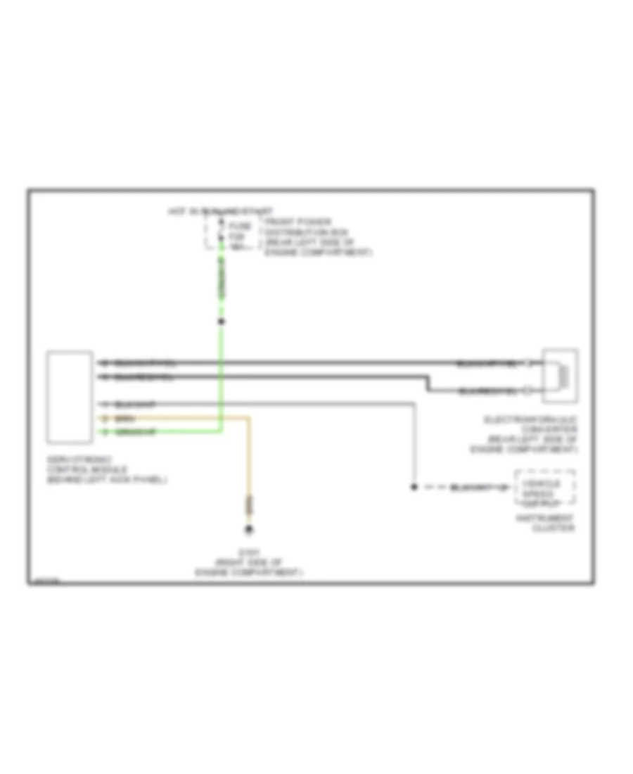
ELECTRONIC POWER STEERING
Electronic Power Steering Wiring Diagram for BMW 535i 1993
 https://portal-diagnostov.com/license.html
Automotive Electricians Portal FZCO
Automotive Electricians Portal FZCO
https://portal-diagnostov.com/license.html
https://portal-diagnostov.com/license.html
Automotive Electricians Portal FZCO
Automotive Electricians Portal FZCOList of elements for Electronic Power Steering Wiring Diagram for BMW 535i 1993:
- Electrohydraulic converter (rear left side of engine compartment)
- Front power distribution box (rear left side of engine compartment)
- Fuse f28 15a
- G101 (right side of engine compartment)
- Hot in run and start
- Instrument cluster
- Servotronic control module (behind left kick panel)
- Vehicle speed output
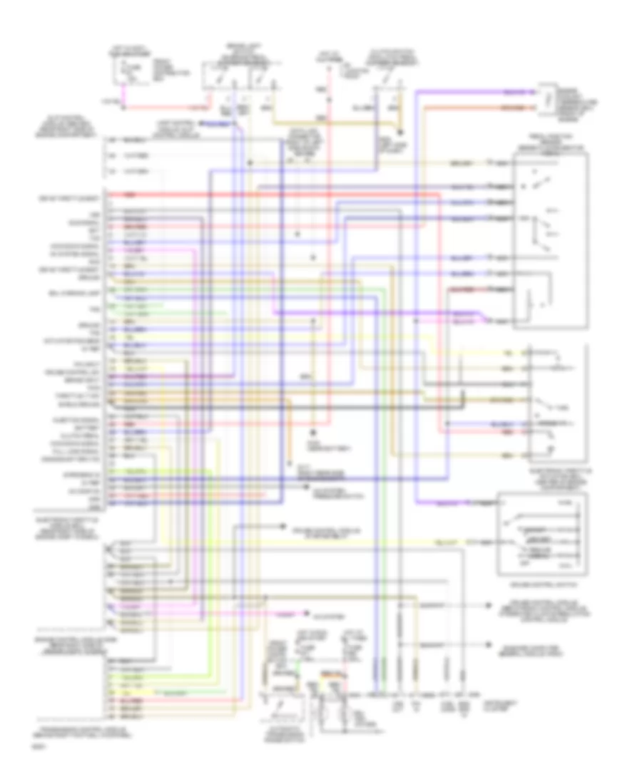
ENGINE PERFORMANCE
3.5L
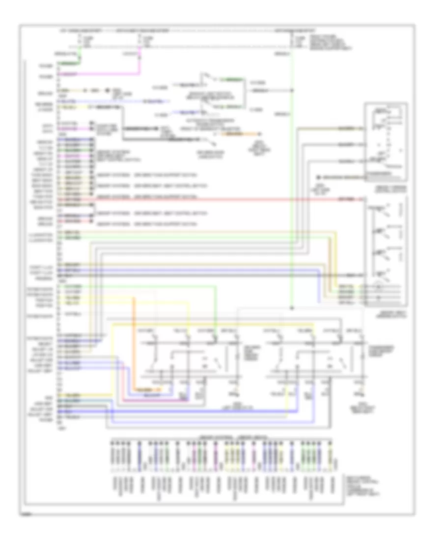
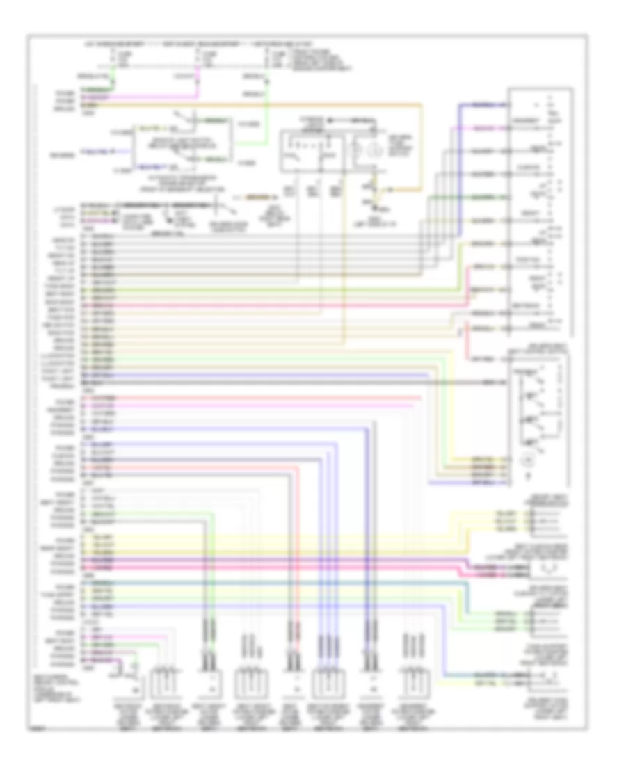
3.5L, Electronic Throttle Control Wiring Diagram for BMW 535i 1993
 https://portal-diagnostov.com/license.html
Automotive Electricians Portal FZCO
Automotive Electricians Portal FZCO
https://portal-diagnostov.com/license.html
https://portal-diagnostov.com/license.html
Automotive Electricians Portal FZCO
Automotive Electricians Portal FZCOList of elements for 3.5L, Electronic Throttle Control Wiring Diagram for BMW 535i 1993:
- 5v ref
- A/c system
- A/c system: pressure switch
- Ac comp on
- Ac system signal
- Acc/set
- Actuator pos sens
- Angle >17
- Automatic transmission range switch
- B+ juncton point
- Battery
- Brake input
- Brake light switch (on brake pedal support bracket)
- Clutch pedal
- Clutch switch (on clutch pedal support bracket)
- Crankshaft rpm (td)
- Cruise control module, servotronic control module, integrated climate regulation control module
- Cruise control module, starter relay
- Cruise control sw
- Cruise control switch
- Data link connector (right of left side shock tower)
- Dec/set
- Dke
- Dkr
- Drive throttle body
- Ect
- Electronic throttle actuator (eml) (center of engine compartment)
- Electronic throttle module (eml) (rear right side of engine compt in e-box)
- Eml indi- cators
- Eml warning lamp
- Eng spd in
- Engine control module (dme) (rear right side of engine compt in e-box)
- Engine coolant temperature sensor (eml) (front of engine)
- Front power distri- bution box
- Front power distribution box
- Fuel cons
- Full load signal
- Fuse #1 15a
- Fuse #17 7.5a
- Fuse #20 10a
- G117 (right rear side of engine compt)
- G120 (near battery)
- G202 (left side of dash)
- Ground
- Hot at all times
- Hot in accy, run and start
- Hot in run and start
- Idle signal
- Injection signal
- Instrument cluster
- Kick-down signal
- Lamp control module, slip control module
- Nca
- Normal
- Off
- On-board computer general module, radio
- P/n in
- P/n input
- Pedal position sensor (beneath accelerator pedal)
- Pwg
- Red
- Resume
- Rxd
- S-program id
- Shield ground
- Slip control module (abs/asc) (rear right side of engine compartment)
- Throttle 17 sw
- Tps
- Transmission control module (behind right footwell kickpanel)
- Txd
- Vss
- Vss out
- X16
- X502
3.5L, Engine Performance Wiring Diagrams, with Electronic Throttle System for BMW 535i 1993
 https://portal-diagnostov.com/license.html
Automotive Electricians Portal FZCO
Automotive Electricians Portal FZCO
https://portal-diagnostov.com/license.html
https://portal-diagnostov.com/license.html
Automotive Electricians Portal FZCO
Automotive Electricians Portal FZCOList of elements for 3.5L, Engine Performance Wiring Diagrams, with Electronic Throttle System for BMW 535i 1993:
- (not used)
- 15a
- 7.5a
- 87a
- A/c system
- Acc
- Automatic transmission range switch
- Aux fan sig
- Battery
- Brake light switch (on brake pedal support)
- Check control module
- Crank rpm
- Crankshaft position/rpm sensor (near distributor)
- Cruise control module, starter relay
- Cyl iden sens
- Cylinder identification sensor (near distributor)
- Data link connector (right of left side shock tower)
- Distributor
- Drive away sig
- Ecm rly ctrl
- Elect throttle module, pin 28
- Elect throttle module, pin 4
- Electronic throttle module, pin 18
- Electronic throttle module, pin 24
- Electronic throttle module, pin 29
- Electronic throttle module, pin 8
- Eng iat sens
- Engine control module (dme) (rear right side of engine compt in e-box)
- Engine control module relay
- Engine intake air temperature sensor (front of engine)
- Engine speed input
- Evap emission
- Evaporative emission valve (left rear side of engine)
- Front power distri- bution box
- Front power distribution box
- Fuel consumption
- Fuel injector valves
- Fuel pump (right side of luggage comp)
- Fuel pump relay
- Fuel pump rly
- Fuse
- Fuse 23
- G117 (right rear side of engine compt)
- G120 (near battery)
- G120 (right side of engine compt)
- G303 (below right rear seat)
- Ground
- Heated oxygen sensor (on catalytic converter)
- Ho2s ground
- Ho2s signal
- Hot at all times
- Hot in run or start
- Iat signal
- Idle signal
- Ign timing
- Ignition
- Ignition coil
- Ignition switch
- Inj 1,3 & 5
- Inj 2,4 & 6
- Instrument cluster
- Junction
- Kva signal
- Malfunction indicator (check engine)
- Mil indicator
- Nca
- Off
- On-board computer, slip control module
- P/n input
- Pedal position sensor (beneath accelerator pedal)
- Point
- Programming vol
- Red
- Run
- Rxd data link
- Slip control module
- Start
- Tcc wk signal
- Timing control
- Torque cutout
- Transmission control module (behind right footwell kickpanel)
- Transmission valve unit
- Txd data link
- Vaf sens
- Vaf signal
- Volume air flow sensor (ahead of oil fill cap)
- Wot signal
- X16
- X502
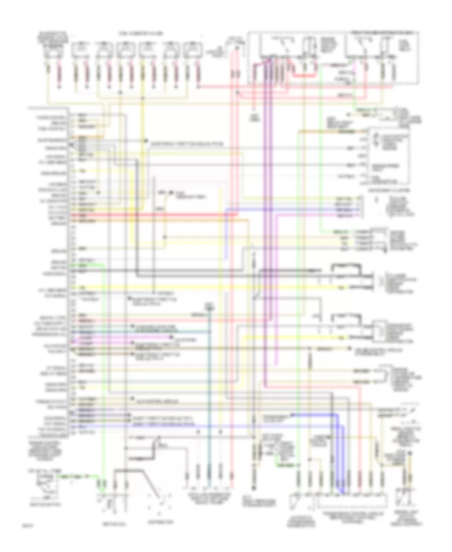
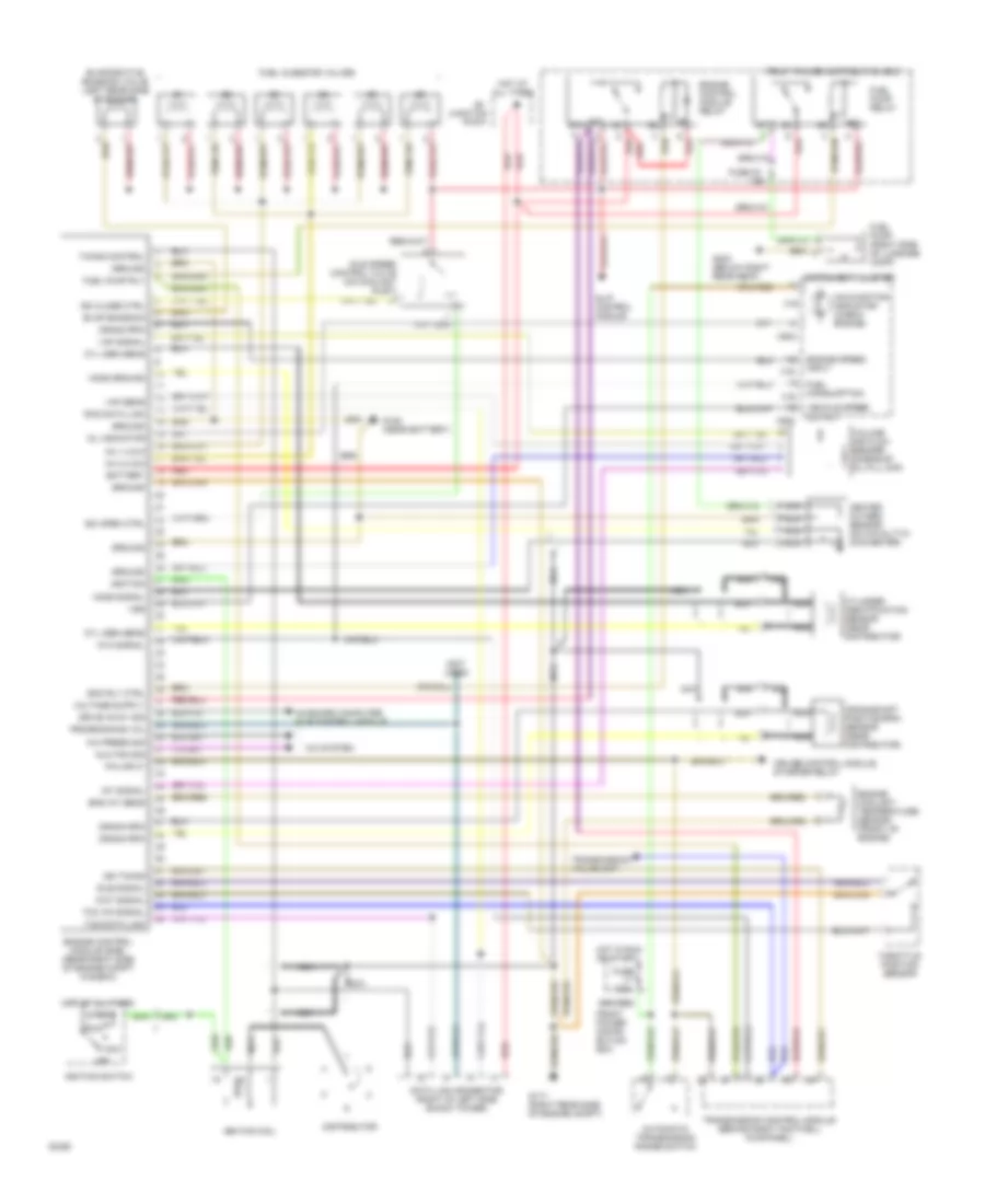
3.5L, Engine Performance Wiring Diagrams, without Electronic Throttle System for BMW 535i 1993
 https://portal-diagnostov.com/license.html
Automotive Electricians Portal FZCO
Automotive Electricians Portal FZCO
https://portal-diagnostov.com/license.html
https://portal-diagnostov.com/license.html
Automotive Electricians Portal FZCO
Automotive Electricians Portal FZCOList of elements for 3.5L, Engine Performance Wiring Diagrams, without Electronic Throttle System for BMW 535i 1993:
- (not used)
- 15a
- 7.5a
- 87a
- A/c press sig
- A/c system
- Acc
- Automatic transmission range switch
- Aux fan sig
- Battery
- Crank rpm
- Crankshaft position/rpm sensor (near distributor)
- Cruise control module, starter relay
- Cyl iden sens
- Cylinder identification sensor (near distributor)
- Data link connector (right of left side shock tower)
- Distributor
- Drive away sig
- Ecm rly ctrl
- Eng iat sens
- Engine control module (dme) (rear right side of engine compt in e-box)
- Engine control module relay
- Engine coolant temperature sensor (front of engine)
- Engine speed input
- Evap emission
- Evaporative emission valve (left rear side of engine)
- Front power distri- bution box
- Front power distribution box
- Fuel consumption
- Fuel injector valves
- Fuel pump (right side of luggage comp)
- Fuel pump relay
- Fuel pump rly
- Fuse
- Fuse 23
- G117 (right rear side of engine compt)
- G120 (near battery)
- G303 (below right rear seat)
- Ground
- Heated oxygen sensor (on catalytic converter)
- Ho2s ground
- Ho2s signal
- Hot at all times
- Hot in run or start
- Iat signal
- Idle signal
- Idle speed control valve (on coolant inlet)
- Ign timing
- Ignition
- Ignition coil
- Ignition switch
- Inj 1,3 & 5
- Inj 2,4 & 6
- Instrument cluster
- Isc close ctrl
- Isc open ctrl
- Junction
- Kva signal
- Malfunction indicator (check engine)
- Mil indicator
- Nca
- Off
- On-board computer, slip control module
- P/n input
- Point
- Programming vol
- Red
- Run
- Rxd data link
- Slip control module
- Start
- Tcc wk signal
- Throttle position sensor
- Timing control
- Transmission control module (behind right footwell kickpanel)
- Transmission valve unit
- Txd data link
- Vaf sens
- Vaf signal
- Vehicle speed output
- Volume air flow sensor (ahead of oil fill cap)
- Vss
- Wot signal
- X16
- X502
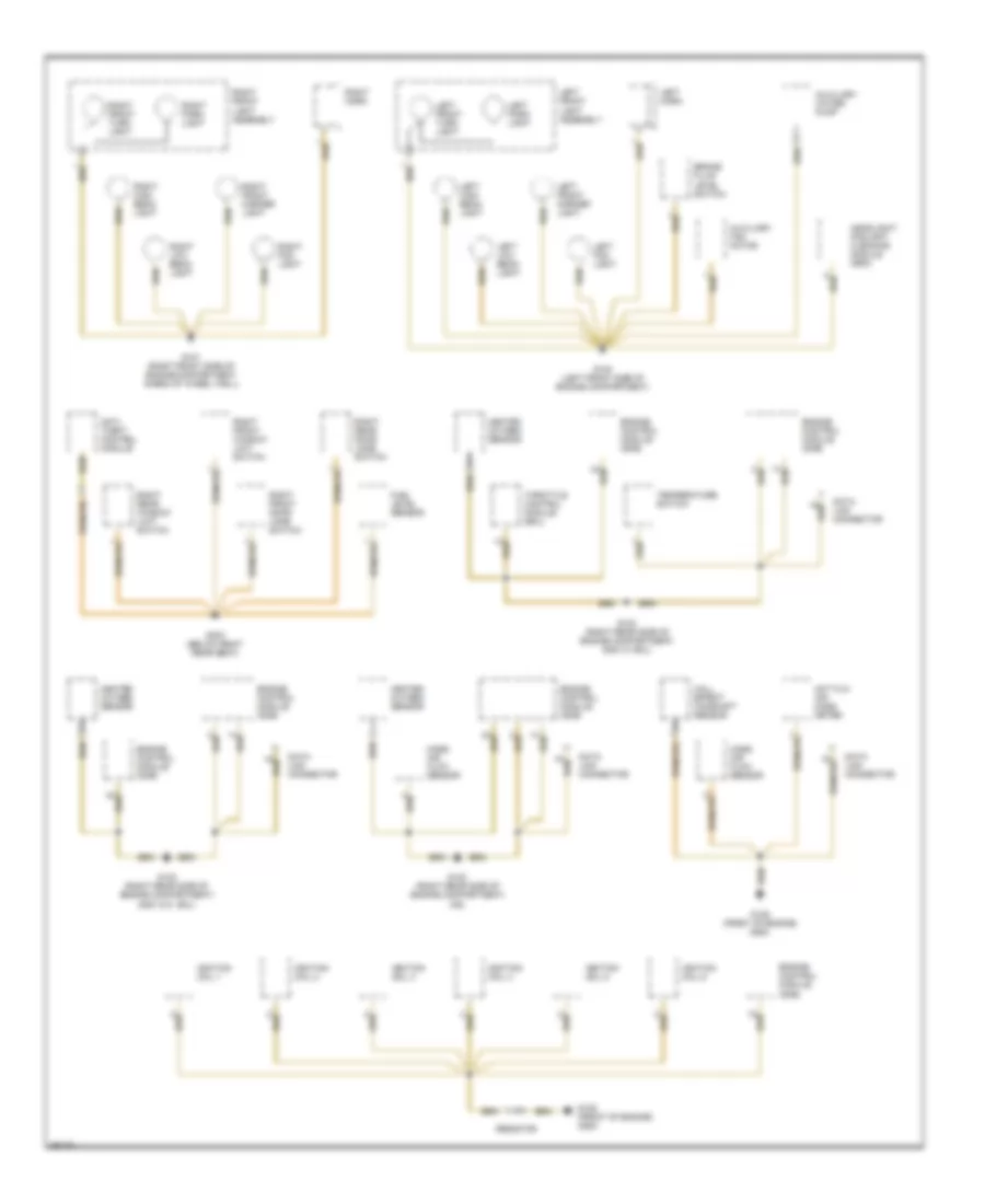
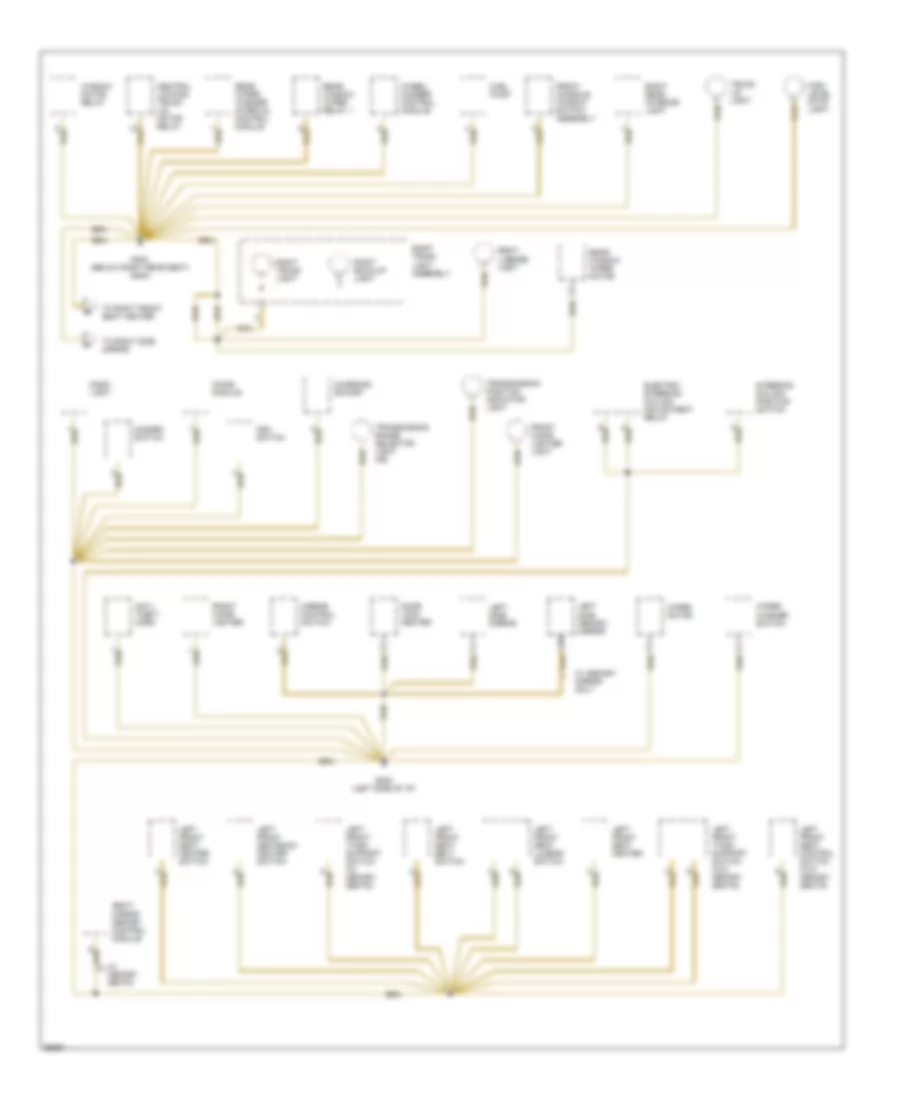
GROUND DISTRIBUTION
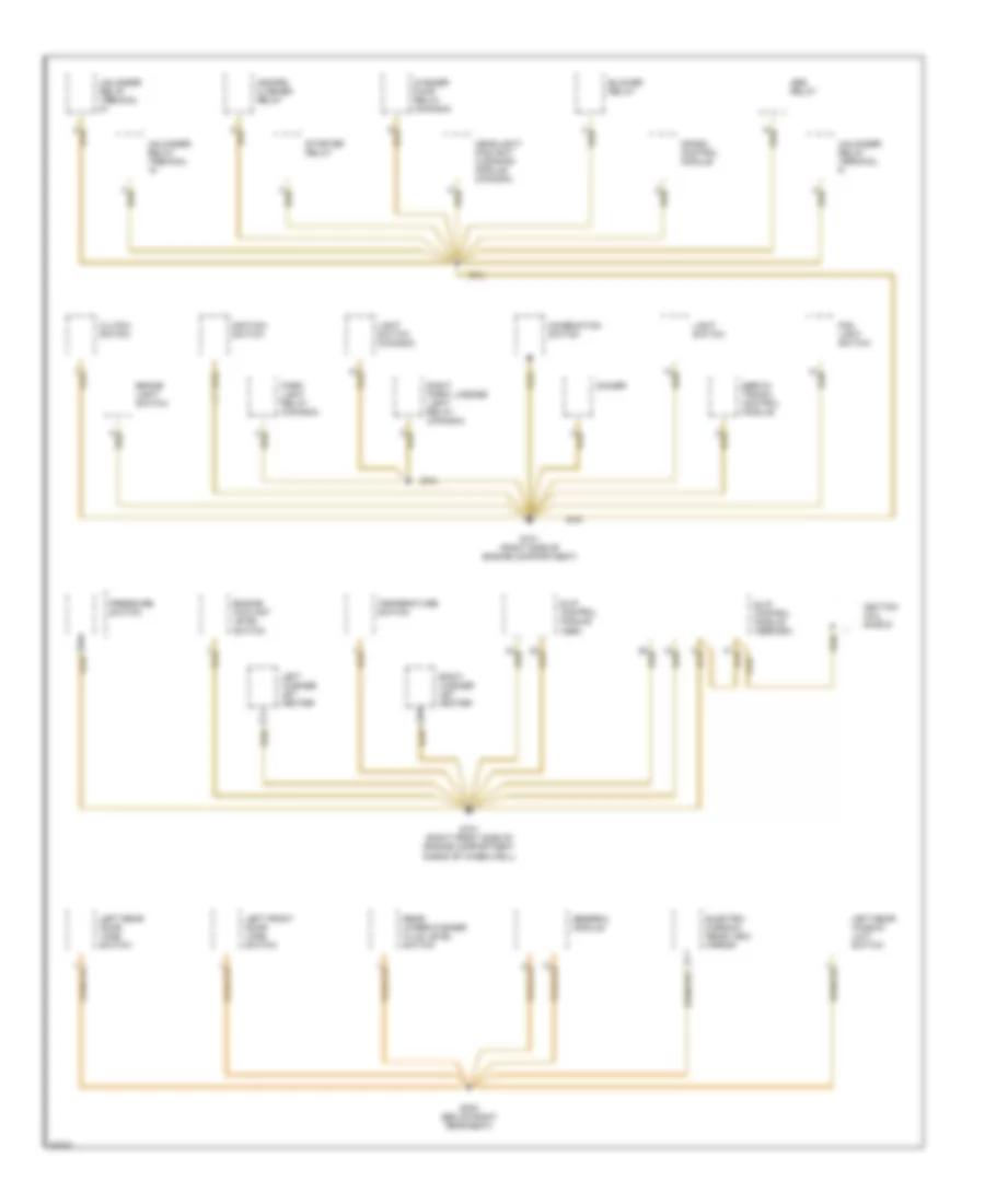
Ground Distribution Wiring Diagram (1 of 7) for BMW 535i 1993
 https://portal-diagnostov.com/license.html
Automotive Electricians Portal FZCO
Automotive Electricians Portal FZCO
https://portal-diagnostov.com/license.html
https://portal-diagnostov.com/license.html
Automotive Electricians Portal FZCO
Automotive Electricians Portal FZCOList of elements for Ground Distribution Wiring Diagram (1 of 7) for BMW 535i 1993:
- Abs relay
- Blower relay
- Brake light switch
- Clutch switch
- Combination switch
- Crash control module
- Dimmer
- Electro- chromic rear view mirror
- Engine coolant level switch
- Fog light switch
- G101 (right front side of engine compartment ahead of wheelwell)
- G101 (right side of engine compartment)
- G303 (below right rear seat)
- General module
- Hazard flasher relay
- Headlight/ foglight cleaning module (canada)
- Ignition coil shield
- Ignition switch
- Left front door jamb switch
- Left rear door jamb switch
- Left rear window limit switch
- Left washer jet heater
- Light switch
- Light switch (canada)
- Park light relay (canada)
- Pressure switch
- Rear wiper/washer fluid level switch
- Right park/ license light relay (canada)
- Right washer jet heater
- Servo- tronic control module
- Slip control module (abs)
- Slip control module (abs/asc)
- Starter relay
- Temperature switch
- Unloader relay terminal r
- Unloader relay treminal
- Washer pump relay (canada)
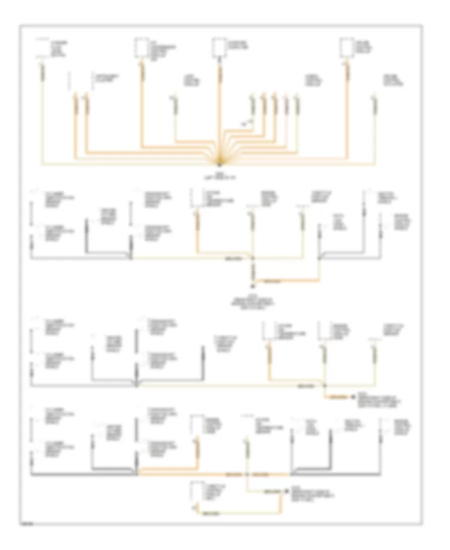
Ground Distribution Wiring Diagram (2 of 7) for BMW 535i 1993
 https://portal-diagnostov.com/license.html
Automotive Electricians Portal FZCO
Automotive Electricians Portal FZCO
https://portal-diagnostov.com/license.html
https://portal-diagnostov.com/license.html
Automotive Electricians Portal FZCO
Automotive Electricians Portal FZCOList of elements for Ground Distribution Wiring Diagram (2 of 7) for BMW 535i 1993:
- 525it
- Abs hydraulic unit
- Blower motor
- Check control module
- Chime module
- Engine hood switch (dwa)
- Ex 525it
- From c g303
- From g303
- Front console window switch assembly
- Fuel pump
- G100 (front left side of engine compartment)
- G202 (left side of i/p)
- G303 (below right rear seat)
- G303 (below right rear seat) (ex 525it)
- Glove box light switch
- High level stop light
- Ihkr/f3 control panel
- Integrated climate regulation control module (ihkr/f3)
- Left front door handle switch
- Left front window limit switch
- Memory mirrors control switch
- Not used
- On-board computer
- Park heating/ ventilation relay box
- Program switch
- Rear defogger/ antenna
- Right front front seatback heater
- Right front seat belt switch
- Right front seat control switch
- Right front seat heater
- Right front seat heater switch
- Right front seat lumbar support switch
- Right front thigh support switch (w/ sport seat)
- Right rear interior light
- Right side memory mirror
- Right side mirror
- Suppression filter
- Transmission control module (egs)
- Trunk lid light
- W/ memory seats
- W/ sport seat
- W/o memory seats
- Washer fluid level switch
- Wheel camber control module (m5)
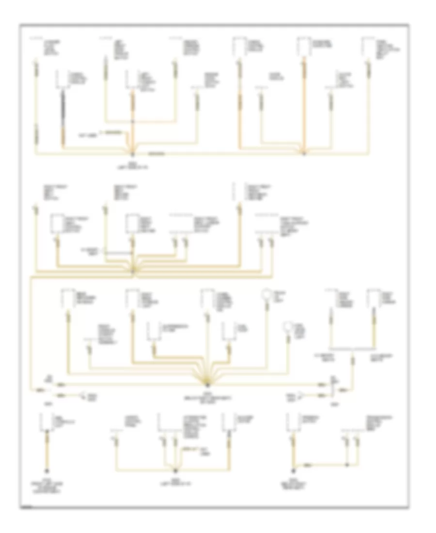
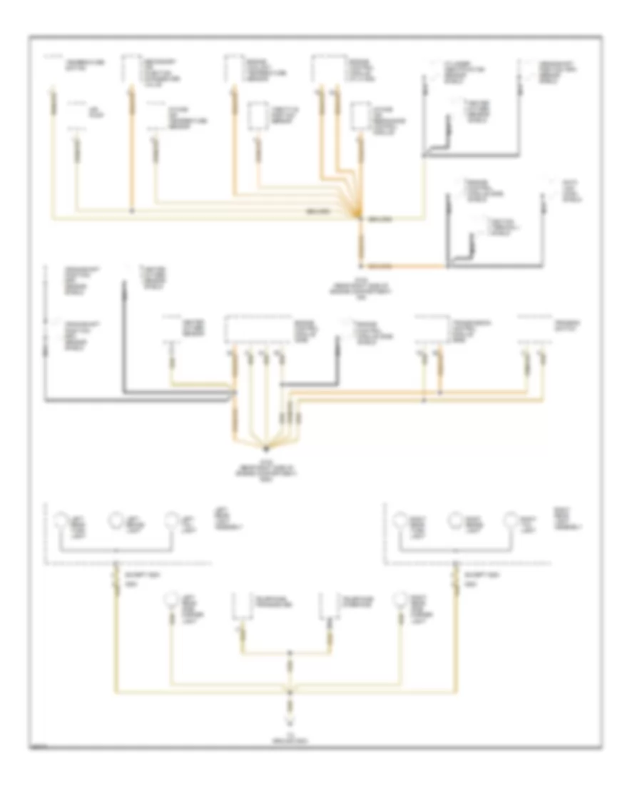
Ground Distribution Wiring Diagram (3 of 7) for BMW 535i 1993
 https://portal-diagnostov.com/license.html
Automotive Electricians Portal FZCO
Automotive Electricians Portal FZCO
https://portal-diagnostov.com/license.html
https://portal-diagnostov.com/license.html
Automotive Electricians Portal FZCO
Automotive Electricians Portal FZCOList of elements for Ground Distribution Wiring Diagram (3 of 7) for BMW 535i 1993:
- Anti- theft control module
- Auxiliary fan motor
- Auxiliary water pump
- Brake fluid level switch
- Data link connector
- Engine control module (dme)
- Fuel level sensor
- G100 (left front side of engine compartment)
- G101 (right front side of engine compartment ahead of wheel well)
- G123 (right rear side of engine compartment) (535i w/ eml)
- G123 (right rear side of engine compartment) (535i w/o eml)
- G123 (right rear side of engine compartment) (m5)
- G125 (front of engine) (525i)
- G303 (below right rear seat)
- Hall effect camshaft sensor
- Headlight/ foglight cleaning module (sra)
- Heated oxygen sensor
- Hot film air mass meter
- Ignition coil 1
- Ignition coil 2
- Ignition coil 3
- Ignition coil 4
- Ignition coil 5
- Ignition coil 6
- Left fog light
- Left front light assembly
- Left front marker light
- Left front turn light
- Left high beam light
- Left horn
- Left low beam light
- Left park light
- Mass air flow sensor
- Resistor
- Right fog light
- Right front door jamb switch
- Right front light assembly
- Right front marker light
- Right front turn light
- Right front window limit switch
- Right high beam light
- Right horn
- Right low beam light
- Right park light
- Right rear door jamb switch
- Right rear window limit switch
- Temperature switch
- Throttle control module (eml)
Ground Distribution Wiring Diagram (4 of 7) for BMW 535i 1993
 https://portal-diagnostov.com/license.html
Automotive Electricians Portal FZCO
Automotive Electricians Portal FZCO
https://portal-diagnostov.com/license.html
https://portal-diagnostov.com/license.html
Automotive Electricians Portal FZCO
Automotive Electricians Portal FZCOList of elements for Ground Distribution Wiring Diagram (4 of 7) for BMW 535i 1993:
- A/c compressor control module (m5)
- Check control module
- Crankshaft position/ rpm sensor shield
- Cruise control actuator
- Cruise control module
- Cylinder identification sensor shield
- Data link conn shield
- Engine control module (dme)
- Engine control module shield
- G123 (rear right side of engine compartment) (535i w/ eml)
- G123 (rear right side of engine compartment) (535i w/o eml w/ egs)
- G123 (rear right side of engine compartment) (535i w/o eml)
- G202 (left side of i/p)
- Heated oxygen sensor shield
- Ignition terminal i shield
- Instrument cluster
- Intake air temperature sensor
- Lamp control module
- Nca
- On-board computer
- Throttle control module (eml)
- Throttle position sensor
- Throttle position sensor shield
- Washer fluid level switch
Ground Distribution Wiring Diagram (5 of 7) for BMW 535i 1993
 https://portal-diagnostov.com/license.html
Automotive Electricians Portal FZCO
Automotive Electricians Portal FZCO
https://portal-diagnostov.com/license.html
https://portal-diagnostov.com/license.html
Automotive Electricians Portal FZCO
Automotive Electricians Portal FZCOList of elements for Ground Distribution Wiring Diagram (5 of 7) for BMW 535i 1993:
- 525it
- Air pump
- Crankshaft position/ rpm sensor shield
- Cylinder identification sensor shield
- Data link conn shield
- Engine control module (dme)
- Engine control module (dme) shield
- Engine control module (m1.2/ s38)
- Engine coolant temperature sensor
- Except 525it
- G123 (rear right side of engine compartment) (525i)
- G123 (rear right side of engine compartment) (m5)
- Heated oxygen sensor
- Heated oxygen sensor shield
- Ignition terminal i shield
- Intake air resonance control module
- Intake air temperature sensor
- Left brake light
- Left rear light assembly
- Left rear side marker light
- Left rear turn light
- Left tail light
- Nca
- Program switch
- Right brake light
- Right rear light assembly
- Right rear side marker light
- Right rear turn light
- Right tail light
- Secondary air injection changeover valve
- Telephone interface
- Telephone transceiver
- Temperature switch
- Throttle position sensor
- To ground g303
- Transmission control module (egs)
Ground Distribution Wiring Diagram (6 of 7) for BMW 535i 1993
 https://portal-diagnostov.com/license.html
Automotive Electricians Portal FZCO
Automotive Electricians Portal FZCO
https://portal-diagnostov.com/license.html
https://portal-diagnostov.com/license.html
Automotive Electricians Portal FZCO
Automotive Electricians Portal FZCOList of elements for Ground Distribution Wiring Diagram (6 of 7) for BMW 535i 1993:
- Cd changer
- Double panel power sunroof control module (525it)
- From left rear light assembly
- Front dome/ map light assembly
- G303 (below right rear seat)
- G303 (below right rear seat) (525it)
- General module (525it)
- Hifi amplifier
- Inertia switch
- Left back-up light
- Left license light
- Left makeup mirror switch
- Left rear interior light
- Left trunk light
- Left trunk light assembly
- Lift gate motor
- Lift gate switch
- Nca
- Radio
- Rear window motor
- Rear window opening switch
- Relay module
- Right back-up light
- Right license light
- Right makeup mirror switch
- Right trunk light
- Sunroof position switch
- Sunroof switch
- Sunroof switch (525it)
- Wiper relay
Ground Distribution Wiring Diagram (7 of 7) for BMW 535i 1993
 https://portal-diagnostov.com/license.html
Automotive Electricians Portal FZCO
Automotive Electricians Portal FZCO
https://portal-diagnostov.com/license.html
https://portal-diagnostov.com/license.html
Automotive Electricians Portal FZCO
Automotive Electricians Portal FZCOList of elements for Ground Distribution Wiring Diagram (7 of 7) for BMW 535i 1993:
- Anti- theft horn
- Asc switch
- Central locking trunk lid motor relay
- Charging socket
- Chime module
- Dash light
- Door lock heater
- Electric steering column adjustment relay
- Front cigar lighter
- Front cigar lighter light
- Front console window switch assembly
- Fuel pump
- G202 (left side of i/p)
- G303 (below right rear seat) (525it)
- Hazard switch
- High level stop light
- Left front seat belt switch
- Left front seat control switch (w/o memory seats)
- Left front seat heater
- Left front seat heater switch
- Left front seat lumbar switch
- Left front seatback heater switch
- Left front thigh support switch (w/ memory seats)
- Left front thigh support switch (w/o memory seats)
- Left side memory mirror
- Left side mirror
- Mirror control switch
- Rear window wiper motor
- Rear window wiper relay 1
- Rear wiper/ washer interval control module
- Right back-up light
- Right license light
- Right rear interior light
- Right trunk light
- Right trunk light assembly
- Seat/ mirror memory control module
- Steering column position switch
- To right front seat heater
- To right side mirror
- Transmission position indicator light
- Transmission range selector light (m5)
- Trunk lid light
- W/ memory mirror only
- W/ memory seats
- Wheel camber control module
- Window motor relay
- Wiper motor
- Wiper/ washer switch
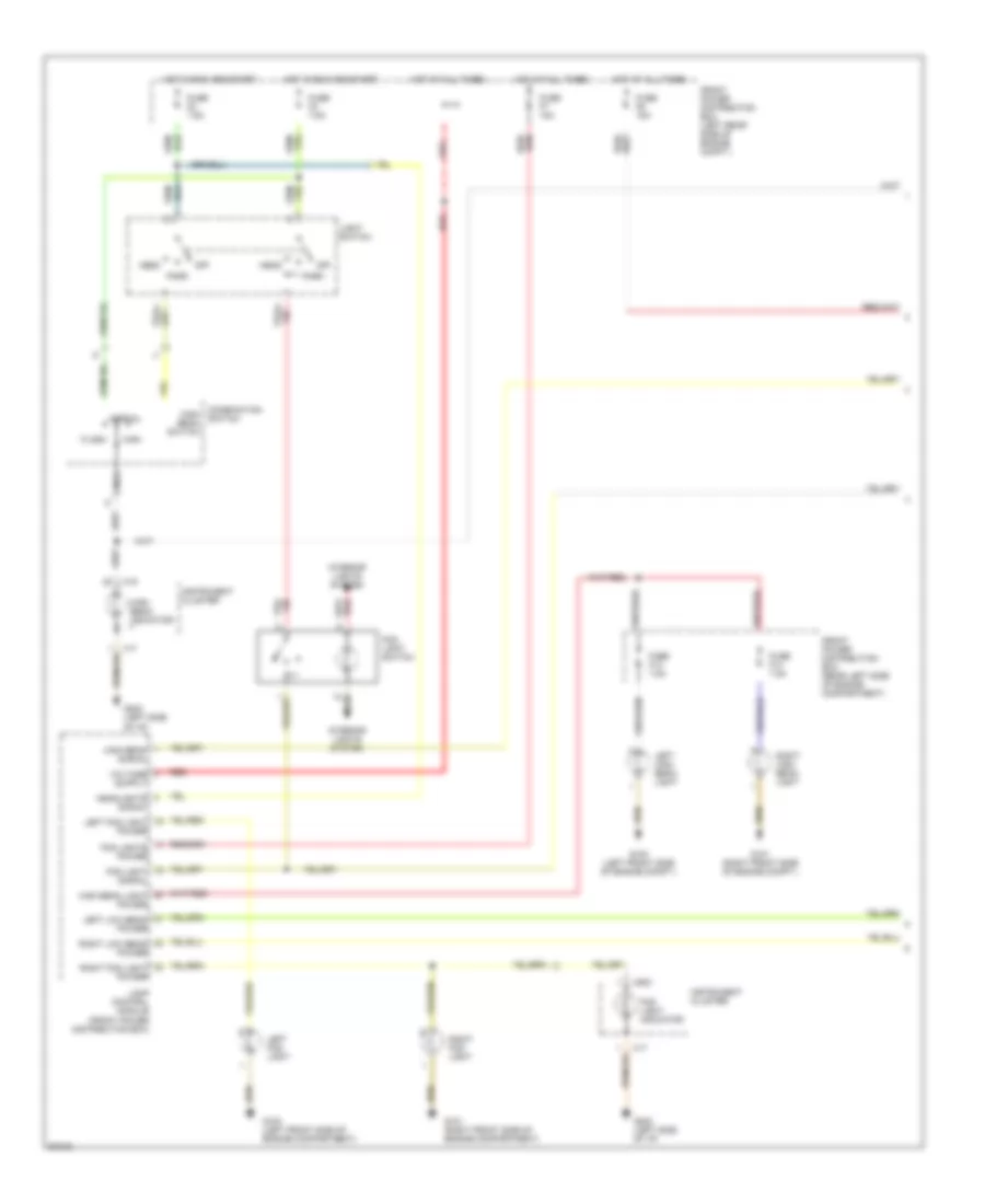
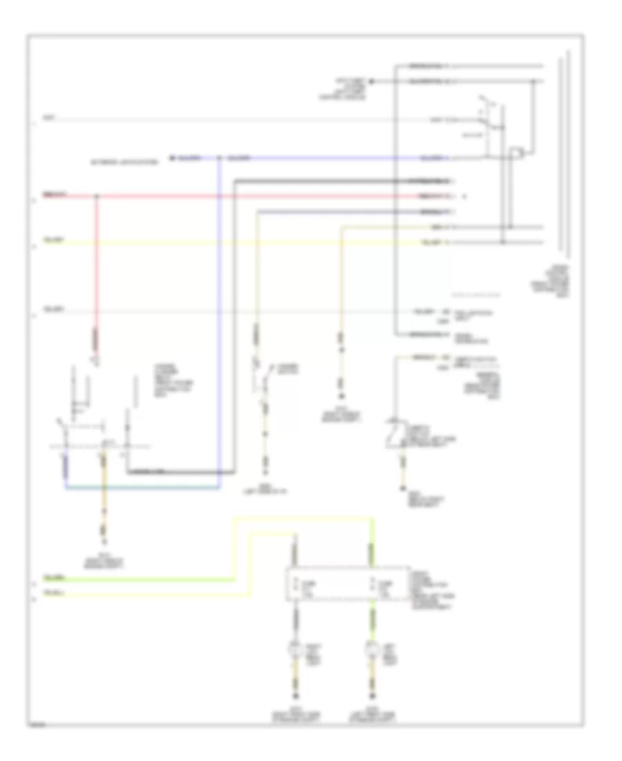
HEADLIGHTS
Headlight Wiring Diagram, with DRL (1 of 2) for BMW 535i 1993
 https://portal-diagnostov.com/license.html
Automotive Electricians Portal FZCO
Automotive Electricians Portal FZCO
https://portal-diagnostov.com/license.html
https://portal-diagnostov.com/license.html
Automotive Electricians Portal FZCO
Automotive Electricians Portal FZCOList of elements for Headlight Wiring Diagram, with DRL (1 of 2) for BMW 535i 1993:
- Combination high beam switch
- Flash
- Fog light indicator
- Fog light signal
- Fog light switch
- Fog lights power
- Front power distribution box (left rear side of engine compt.)
- Front power distribution box (rear left side of engine compartment)
- Fuse f13 7.5a
- Fuse f14 7.5a
- Fuse f2 7.5a
- Fuse f3 7.5a
- Fuse f6 15a
- Fuse f7 15a
- G100 (left front side of engine compartment)
- G100 (left front side of engine compt.)
- G101 (right front side of engine compartment)
- G101 (right front side of engine compt.)
- G202 (left side of i/p)
- Head
- Headlights signal
- High
- High beam indicator
- High beam light power
- High beam signal
- Hot at all times
- Hot in run and start
- Instrument cluster
- Interior lights system
- Lamp control module (front power distribution box)
- Left fog light
- Left fog light power
- Left high beam light
- Left low beam power
- Light switch
- Nca
- Normal
- Off
- Park
- Red
- Right fog light
- Right fog light power
- Right high beam light
- Right low beam power
- Switch
- X16
- X17
- X502
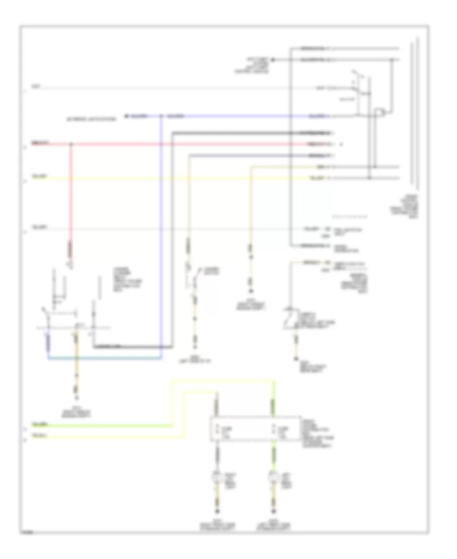
Headlight Wiring Diagram, with DRL (2 of 2) for BMW 535i 1993
 https://portal-diagnostov.com/license.html
Automotive Electricians Portal FZCO
Automotive Electricians Portal FZCO
https://portal-diagnostov.com/license.html
https://portal-diagnostov.com/license.html
Automotive Electricians Portal FZCO
Automotive Electricians Portal FZCOList of elements for Headlight Wiring Diagram, with DRL (2 of 2) for BMW 535i 1993:
- Anti-theft system (anti-theft control module)
- Crash control module (front power distribution box)
- Crash information
- Exterior lights system
- Fog lights on input
- Front power distribution box (rear left side of engine compartment)
- Fuse f10 7.5a
- Fuse f11 7.5a
- G100 (left front side of engine compt.)
- G101 (right front side of engine compt.)
- G101 (right side of engine compt.)
- G202 (left side of i/p)
- G303 (below right rear seat)
- General module (rear power distribution box)
- Hazard flasher relay (front power distribution box)
- Hazard switch
- Inertia switch (below left side of rear seat)
- Inertia switch input
- Left low beam light
- Right low beam light
- X253
- X255
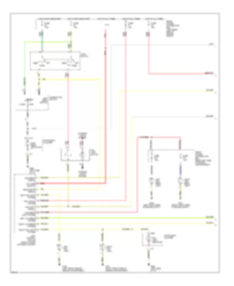
Headlight Wiring Diagram, without DRL (1 of 2) for BMW 535i 1993
 https://portal-diagnostov.com/license.html
Automotive Electricians Portal FZCO
Automotive Electricians Portal FZCO
https://portal-diagnostov.com/license.html
https://portal-diagnostov.com/license.html
Automotive Electricians Portal FZCO
Automotive Electricians Portal FZCOList of elements for Headlight Wiring Diagram, without DRL (1 of 2) for BMW 535i 1993:
- Combination high beam switch
- Flash
- Fog light indicator
- Fog light signal
- Fog light switch
- Fog lights power
- Front power distribution box (left rear side of engine compt.)
- Front power distribution box (rear left side of engine compartment)
- Fuse f13 7.5a
- Fuse f14 7.5a
- Fuse f2 7.5a
- Fuse f3 7.5a
- Fuse f6 15a
- Fuse f7 15a
- G100 (left front side of engine compartment)
- G100 (left front side of engine compt.)
- G101 (right front side of engine compartment)
- G101 (right front side of engine compt.)
- G202 (left side of i/p)
- Head
- Headlights signal
- High
- High beam indicator
- High beam light power
- High beam signal
- Hot at all times
- Hot in run and start
- Instrument cluster
- Interior lights system
- Lamp control module (front power distribution box)
- Left fog light
- Left fog light power
- Left high beam light
- Left low beam power
- Light switch
- Nca
- Normal
- Off
- Park
- Red
- Right fog light
- Right fog light power
- Right high beam light
- Right low beam power
- Switch
- X16
- X17
- X502
Headlight Wiring Diagram, without DRL (2 of 2) for BMW 535i 1993
 https://portal-diagnostov.com/license.html
Automotive Electricians Portal FZCO
Automotive Electricians Portal FZCO
https://portal-diagnostov.com/license.html
https://portal-diagnostov.com/license.html
Automotive Electricians Portal FZCO
Automotive Electricians Portal FZCOList of elements for Headlight Wiring Diagram, without DRL (2 of 2) for BMW 535i 1993:
- Anti-theft system (anti-theft control module)
- Crash control module (front power distribution box)
- Crash information
- Exterior lights system
- Fog lights on input
- Front power distribution box (rear left side of engine compartment)
- Fuse f10 7.5a
- Fuse f11 7.5a
- G100 (left front side of engine compt.)
- G101 (right front side of engine compt.)
- G101 (right side of engine compt.)
- G202 (left side of i/p)
- G303 (below right rear seat)
- General module (rear power distribution box)
- Hazard flasher relay (front power distribution box)
- Hazard switch
- Inertia switch (below left side of rear seat)
- Inertia switch input
- Left low beam light
- Right low beam light
- X253
- X255
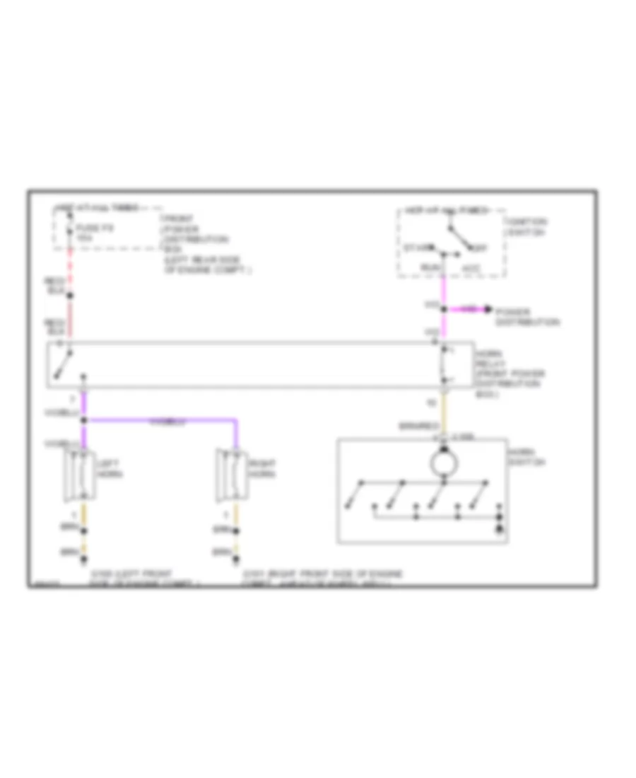
HORN
Horn Wiring Diagram for BMW 535i 1993
 https://portal-diagnostov.com/license.html
Automotive Electricians Portal FZCO
Automotive Electricians Portal FZCO
https://portal-diagnostov.com/license.html
https://portal-diagnostov.com/license.html
Automotive Electricians Portal FZCO
Automotive Electricians Portal FZCOList of elements for Horn Wiring Diagram for BMW 535i 1993:
- (left front
- (right front side of engine
- Acc
- Front power distribution box (left rear side of engine compt.)
- Fuse f9 15a
- G100 side of engine compt.)
- G101 compt., ahead of wheel well)
- Horn relay (front power distribution box)
- Horn switch
- Hot at all times
- Ignition switch
- Left horn
- Off
- Power distribution
- Right horn
- Run
- Start
- X168
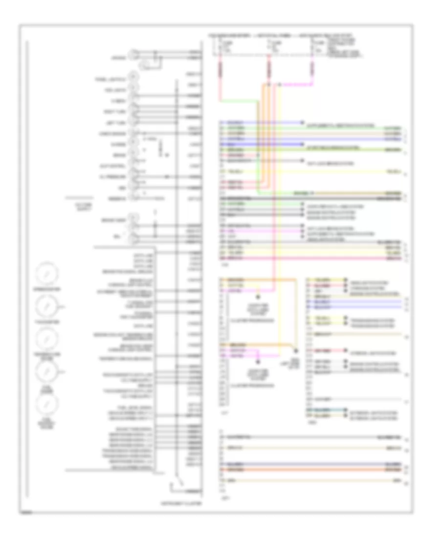
INSTRUMENT CLUSTER
Instrument Cluster Wiring Diagram (1 of 2) for BMW 535i 1993
 https://portal-diagnostov.com/license.html
Automotive Electricians Portal FZCO
Automotive Electricians Portal FZCO
https://portal-diagnostov.com/license.html
https://portal-diagnostov.com/license.html
Automotive Electricians Portal FZCO
Automotive Electricians Portal FZCOList of elements for Instrument Cluster Wiring Diagram (1 of 2) for BMW 535i 1993:
- Abs
- Air bag
- Anti-lock brake system
- Brake
- Brake fluid warning lamp control
- Brake pad signal ground
- Brake pad wear warning lamp control
- Brake wear
- Charge
- Check engine
- Cluster programming
- Computer data lines system
- Data line
- Eml
- Engine controls system
- Engine coolant temperature sensor ground
- Exterior lights system
- Fog lights
- Front power distribution box (rear left side of engine compt.)
- Fuel economy gauge
- Fuel gauge
- Fuel level signal
- Fuse 10a
- Fuse 15a
- Fuse f17 7.5a
- G202 (left side of i/p)
- Gear range signal (l1)
- Gear range signal (l2)
- Gear range signal (l3)
- Gear range signal (l4)
- Ground
- Headlights system
- Hi beam
- Hot at all times
- Hot in accy, run and start
- Hot in run and start
- Instrument cluster
- Interior lights system
- Left turn
- Oil pressure
- Panel lights (3)
- Reserve
- Right turn
- Rxd diagnostic data link
- Sia reset/ service interval indicator reset
- Slip control
- Sound tone signal
- Speedometer
- Starting/charging system
- Tachometer
- Td signal for tachometer
- Temperature gauge
- Temperature gauge signal
- Ti signal for fuel economy
- Transmission mode signal
- Transmissions system
- Txd diagnostic data link
- Vehicle speed input (+)
- Vehicle speed input (-)
- Vehicle speed signal
- Warnings system
- X16
- X16/1
- X16/10
- X16/12
- X16/13
- X16/15
- X16/16
- X16/17
- X16/18
- X16/2
- X16/20
- X16/21
- X16/22
- X16/23
- X16/24
- X16/25
- X16/26
- X16/3
- X16/4
- X16/5
- X16/6
- X16/7
- X16/8
- X17
- X17/1
- X17/13
- X17/14
- X17/15
- X17/2
- X17/3
- X271
- X271/10
- X271/2
- X271/4
- X271/7
- X271/8
- X502
- X502/1
- X502/11
- X502/14
- X502/16
- X502/17
- X502/18
- X502/2
- X502/23
- X502/25
- X502/26
- X502/3
- X502/4
- X502/5
- X502/6
- X502/8
- X502/9
Instrument Cluster Wiring Diagram (2 of 2) for BMW 535i 1993
 https://portal-diagnostov.com/license.html
Automotive Electricians Portal FZCO
Automotive Electricians Portal FZCO
https://portal-diagnostov.com/license.html
https://portal-diagnostov.com/license.html
Automotive Electricians Portal FZCO
Automotive Electricians Portal FZCOList of elements for Instrument Cluster Wiring Diagram (2 of 2) for BMW 535i 1993:
- (525i)
- (525i) (535i)
- (535i)
- (not used)
- 525i & 535i
- 525i only
- 525i touring
- 535i only
- Anti- theft system
- Automatic transmission range switch
- Brake fluid level switch
- Brake light switch
- Check control module
- Check control reset button
- Cruise control module
- Data lines
- Driver's door jamb switch
- E-box fan (535i)
- Engine control module
- Engine coolant level switch
- Engine coolant temperature sensor
- Exterior lights system
- Fuel gauge
- Fuel level sensor
- G100
- G101
- G103
- G202
- G303
- General module
- Integrated climate regulation control module
- Left front brake sensor
- Nca
- Oil level sensor
- Oil pressure switch
- On-board computer
- On-board computer/ multi- function clock
- Park brake signal
- Park brake switch
- Radio
- Rear washer fluid level switch
- Reserve tank contact
- Right rear brake sensor
- Servo- tronic control module
- Slip control module
- Starter relay
- Throttle control module
- Transmissions system
- Vehicle speed sensor
- Vehicle speed signal
- W/ eml
- W/o eml
- Washer fluid level switch
- X18
- X18155
- X19
- X253
MEMORY SYSTEMS
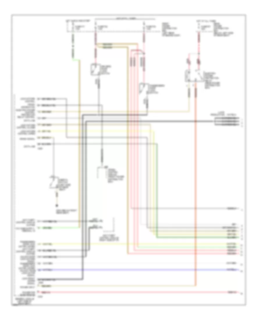
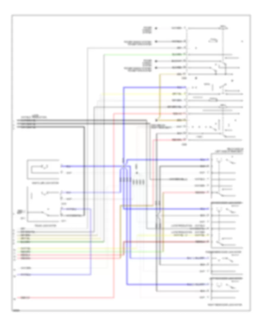
Memory Mirrors Wiring Diagram for BMW 535i 1993
 https://portal-diagnostov.com/license.html
Automotive Electricians Portal FZCO
Automotive Electricians Portal FZCO
https://portal-diagnostov.com/license.html
https://portal-diagnostov.com/license.html
Automotive Electricians Portal FZCO
Automotive Electricians Portal FZCOList of elements for Memory Mirrors Wiring Diagram for BMW 535i 1993:
- (driver's seat, seat control switch)
- (driver's thigh support switch)
- (memory seats)
- Adjust hor
- Adjust l/r
- Adjust vert
- Anti- theft system
- Automatic transmission range switch (front of gearshift selector)
- Back back
- Back fwd
- Backup light switch (below center console)
- Computer data lines system
- Cushion
- Data
- Down
- Driver's
- Driver's door jamb switch
- Driver's side memory mirror
- Front power distribution box (rear left side of engine compartment)
- Funct illum
- Fuse f12 15a
- Fuse f16 30a
- Fuse f18 15a
- G202 (left side of i/p)
- G303 (below right rear seat)
- Gnd
- Ground
- Head dn
- Head up
- Headrest
- Height dn
- Height up
- Hor/vert
- Hot in accy, run and start
- Hot in run and start
- Illumination
- L/r and u/d
- Left
- Lf door
- Mem switch
- Mem1
- Mem2
- Mem3
- Memory mirrors control switch
- Memory seat/ mirrors switch
- Memory systems
- Memory systems (driver's seat, seat control switch)
- Nca
- Passenger's
- Passenger's side memory mirror
- Position
- Potentiomtr
- Power
- Program
- Pwr/gnd
- Rear height
- Reverse
- Right
- Seat back
- Seat fwd
- Seat height
- Seat/mirror memory control module (underside of left front seat)
- Select
- Thigh back
- Thigh fwd
- Thigh spprt
- Tilt dn
- Tilt up
- W/ egs
- W/o egs
- X18181
- X601
- X602
- X648
- X649
- X653
- X654
- X655
- X656
- X657
Memory Seat Wiring Diagram for BMW 535i 1993
 https://portal-diagnostov.com/license.html
Automotive Electricians Portal FZCO
Automotive Electricians Portal FZCO
https://portal-diagnostov.com/license.html
https://portal-diagnostov.com/license.html
Automotive Electricians Portal FZCO
Automotive Electricians Portal FZCOList of elements for Memory Seat Wiring Diagram for BMW 535i 1993:
- (lower left front seatback)
- Anti- theft system
- Automatic transmission range selector (front of gearshift selector)
- Back
- Back back
- Back fwd
- Backup light switch (below center console)
- Computer data lines system
- Cushion
- Data
- Down
- Driver's door jamb switch
- Driver's seat cushion tilt motor (under left front seat)
- Driver's seat, seat control switch
- Driver's thigh support motor (under left front seat)
- Driver's thigh support switch
- Front
- Front power distribution box (rear left side of engine compartment)
- Funct light
- Fuse f12 15a
- Fuse f16 30a
- Fuse f18 15a
- Fwd
- G202 (left side of i/p)
- G303 (below right rear seat)
- Ground
- Head dn
- Head up
- Headrest
- Headrest motor (under driver's seat)
- Headrest potentiometer (lower left front seatback)
- Height
- Height dn
- Height up
- Hot in accy, run and start
- Hot in run and start
- Illumination
- Interior lights system
- Lf door
- Mem switch
- Mem1
- Mem2
- Mem3
- Memory seat/ mirrors switch
- Nca
- Position
- Power
- Program
- Pwr/gnd
- Rear height
- Reverse
- Rwd
- Seat back
- Seat cushion rear height potentiometer (lower left front seatback)
- Seat fwd
- Seat height
- Seat height motor (under driver's seat)
- Seat height potentiometer
- Seat motor (under driver's seat)
- Seat movement potentiometer (lower left front seatback)
- Seat/mirror memory control module (underside of left front seat)
- Seatback
- Seatback motor (under driver's seat)
- Seatback potentiometer (lower left front seatback)
- Thigh back
- Thigh fwd
- Thigh spprt
- Thigh support potentiometer (lower left front seatback)
- Tilt dn
- Tilt up
- W/ egs
- W/o egs
- X18181
- X602
- X648
- X649
- X653
- X654
- X655
- X656
- X657
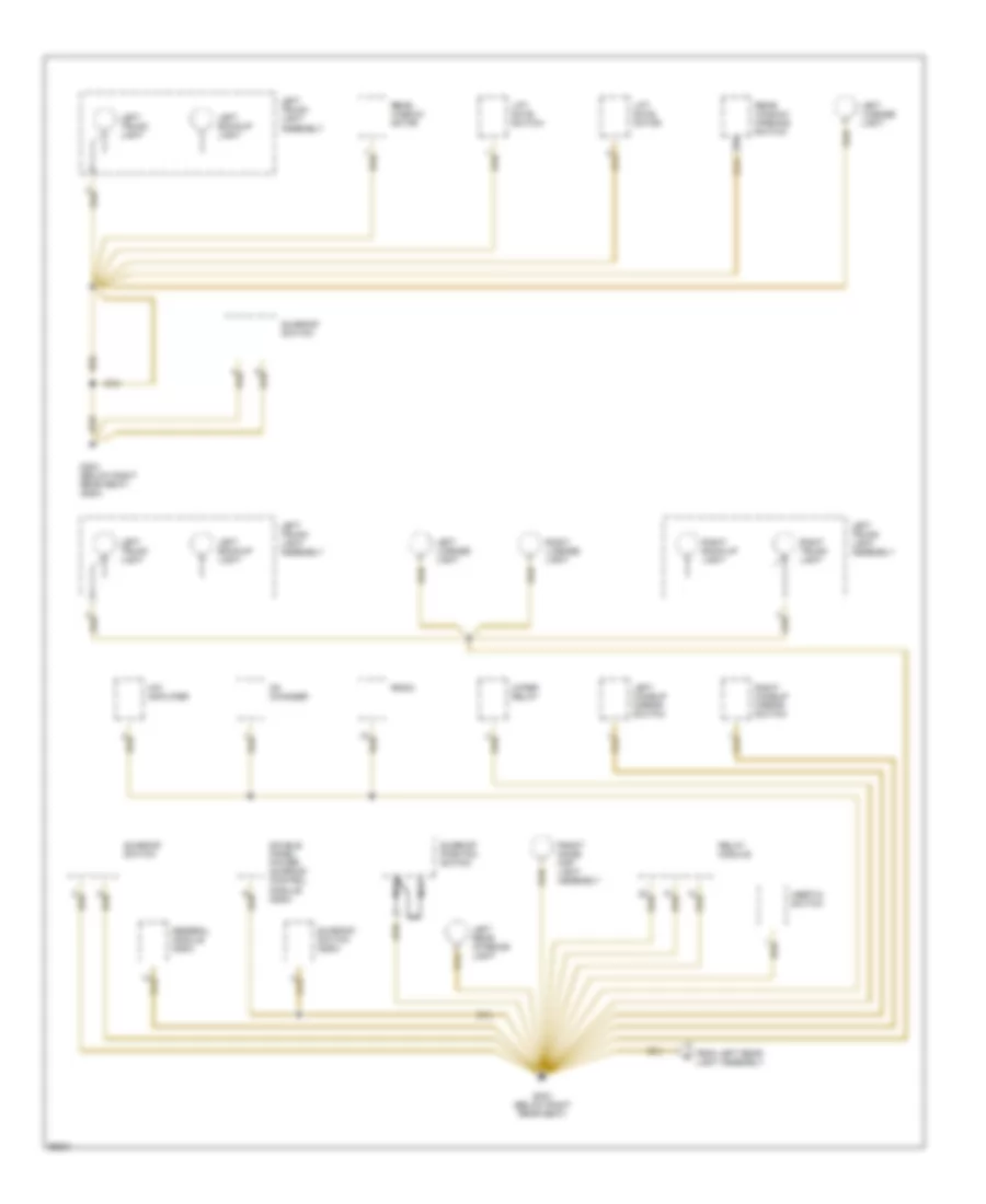
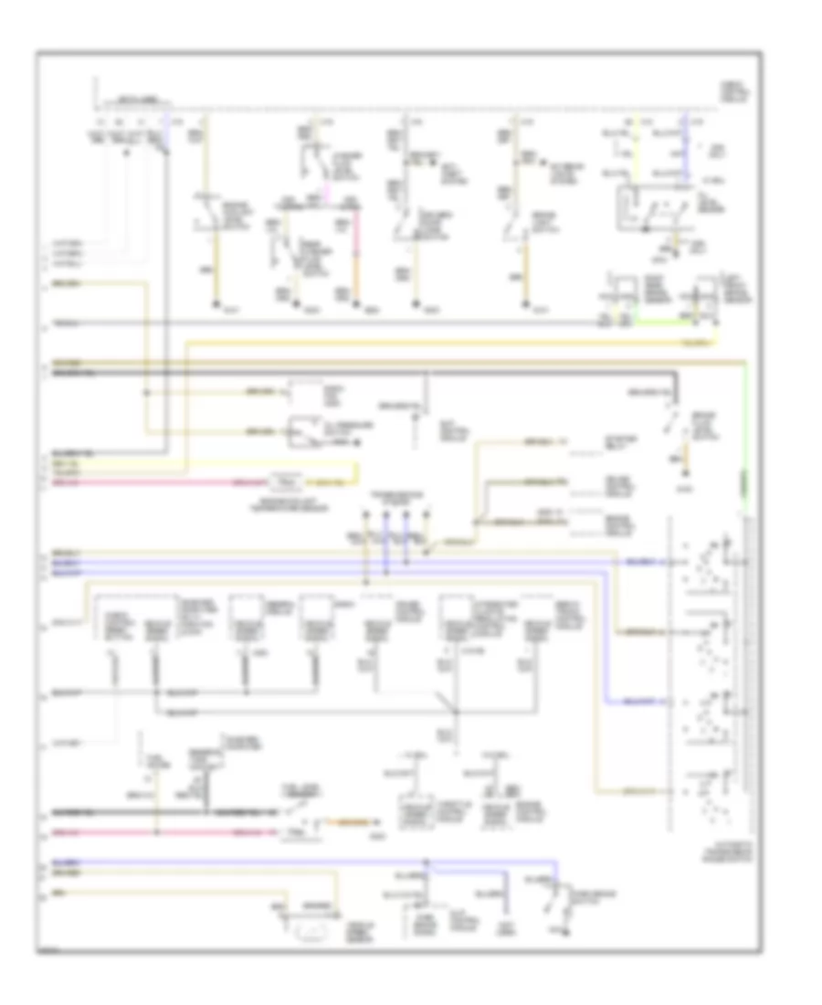
POWER DISTRIBUTION
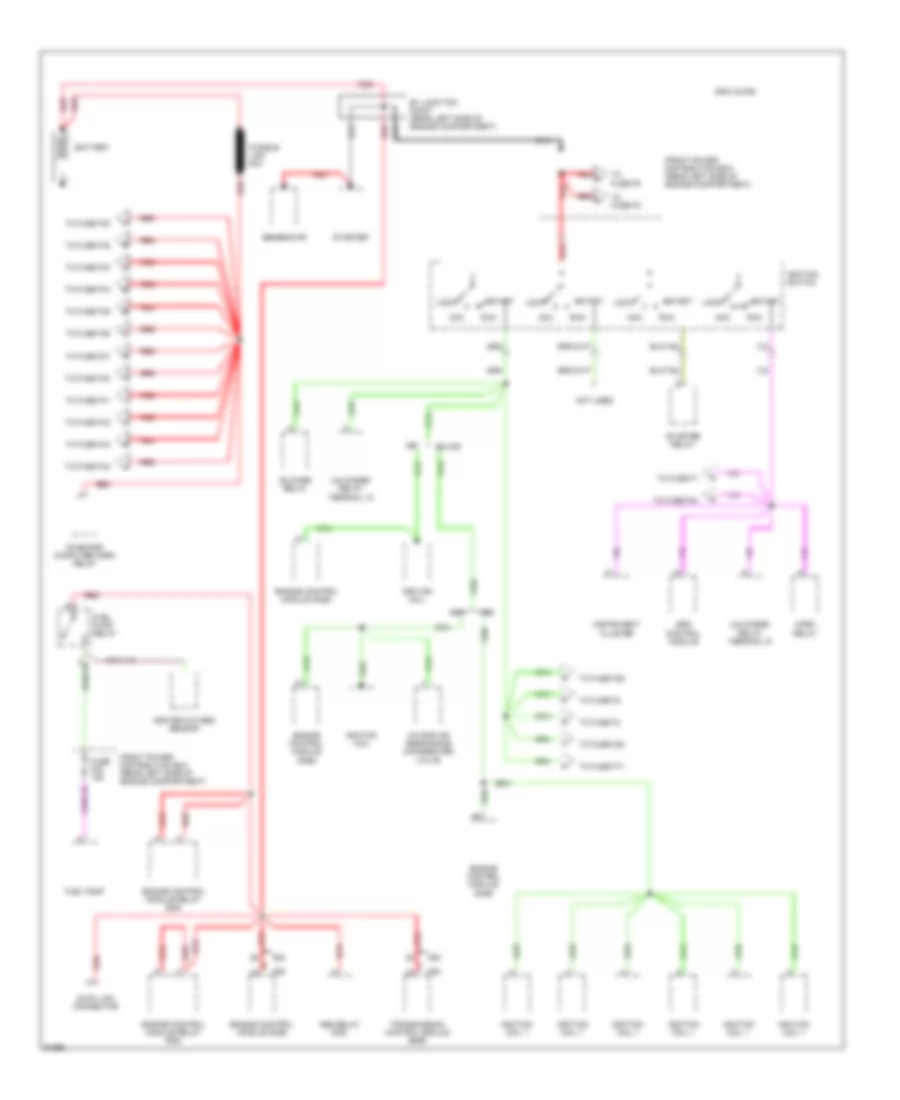
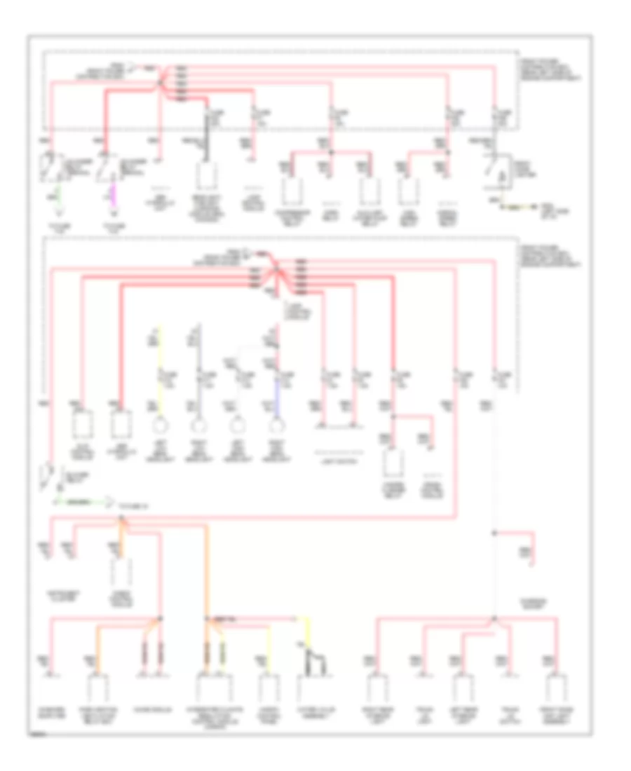
Power Distribution Wiring Diagram (1 of 6) for BMW 535i 1993
 https://portal-diagnostov.com/license.html
Automotive Electricians Portal FZCO
Automotive Electricians Portal FZCO
https://portal-diagnostov.com/license.html
https://portal-diagnostov.com/license.html
Automotive Electricians Portal FZCO
Automotive Electricians Portal FZCOList of elements for Power Distribution Wiring Diagram (1 of 6) for BMW 535i 1993:
- 525i/t & 535i
- Abs relay (535)
- Acc
- B+ junction point (rear left side of engine compartment)
- Battery
- Blower relay
- Data link connector
- Engine control module (dme)
- Engine control module relay (525)
- Engine control module relay (535)
- Ex m30
- Front power distribution box (rear left side of engine compartment)
- Fuel pump
- Fuel pump relay
- Fuse f23 15a
- Fusible link 80a
- Generator
- Heated oxygen sensor
- Horn relay
- Ignition coil
- Ignition coil 1
- Ignition switch
- Instrument cluster
- Intake air resonance changeover valve
- Lock
- M30
- M50
- Not used
- On-board computer horn relay
- Red
- Run
- S38
- Srs control module
- Start
- Starter
- Starter relay
- To fuse f1
- To fuse f17
- To fuse f2
- To fuse f24
- To fuse f28
- To fuse f29
- To fuse f3
- To fuse f30
- To fuse f32
- To fuse f33
- To fuse f34
- To fuse f35
- To fuse f36
- To fuse f37
- To fuse f40
- To fuse f41
- To fuse f42
- To fuse f43
- To fuse f44
- To fuse f5
- To fuse f9
- Transmission control module (egs)
- Unloader relay terminal 15
- Unloader relay terminal r
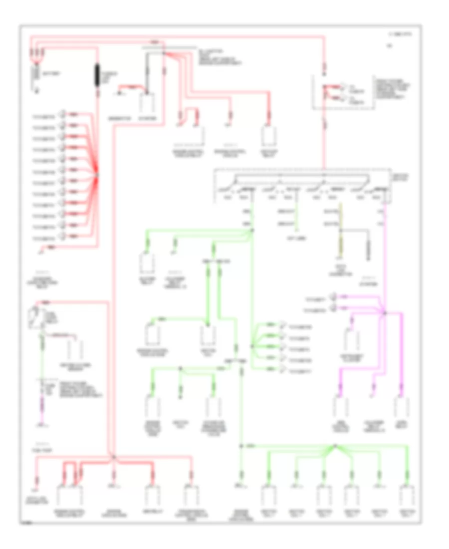
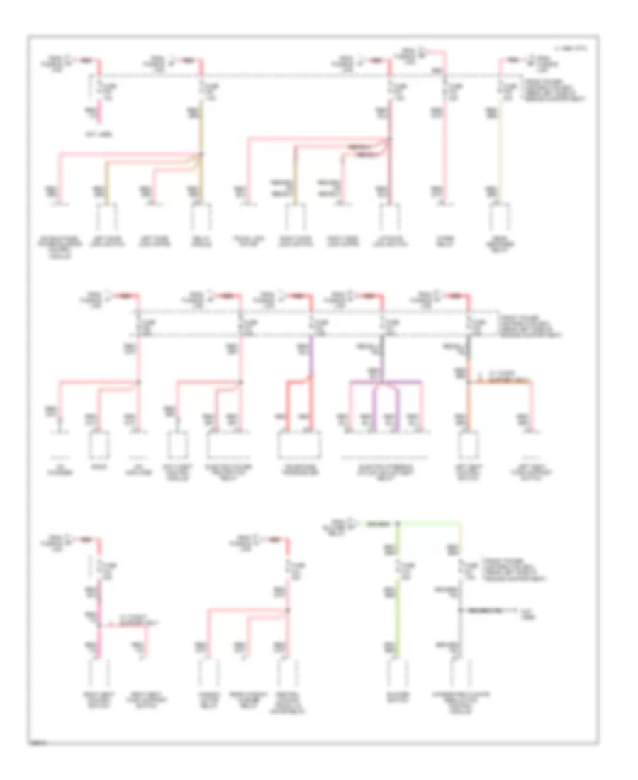
Power Distribution Wiring Diagram (2 of 6) for BMW 535i 1993
 https://portal-diagnostov.com/license.html
Automotive Electricians Portal FZCO
Automotive Electricians Portal FZCO
https://portal-diagnostov.com/license.html
https://portal-diagnostov.com/license.html
Automotive Electricians Portal FZCO
Automotive Electricians Portal FZCOList of elements for Power Distribution Wiring Diagram (2 of 6) for BMW 535i 1993:
- 1995 vftc c
- Abs relay
- Acc
- Air pump relay
- B+ junction point (rear left side of engine compartment)
- Battery
- Blower relay
- Data link connector
- Engine control module
- Engine control module (dme)
- Engine control module relay
- Engine module (dme)
- Ex m30
- Front power distribution box (rear left side of engine compartment)
- Fuel pump
- Fuel pump relay
- Fuse f23 15a
- Fusible link 80a
- Generator
- Heated oxygen sensor
- Horn relay
- Ignition coil
- Ignition coil 1
- Ignition switch
- Instrument cluster
- Intake air resonance changeover valve
- Lock
- M30
- M50
- Not used
- On-board computer horn relay
- Red
- Run
- S38
- Srs control module
- Start
- Starter
- To fuse f1
- To fuse f17
- To fuse f2
- To fuse f24
- To fuse f28
- To fuse f29
- To fuse f3
- To fuse f30
- To fuse f32
- To fuse f33
- To fuse f34
- To fuse f35
- To fuse f36
- To fuse f37
- To fuse f40
- To fuse f41
- To fuse f42
- To fuse f43
- To fuse f44
- To fuse f5
- To fuse f9
- Transmission control module (egs)
- Unloader relay terminal 15
- Unloader relay terminal r
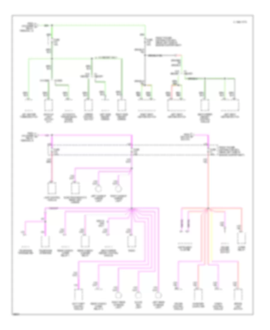
Power Distribution Wiring Diagram (3 of 6) for BMW 535i 1993
 https://portal-diagnostov.com/license.html
Automotive Electricians Portal FZCO
Automotive Electricians Portal FZCO
https://portal-diagnostov.com/license.html
https://portal-diagnostov.com/license.html
Automotive Electricians Portal FZCO
Automotive Electricians Portal FZCOList of elements for Power Distribution Wiring Diagram (3 of 6) for BMW 535i 1993:
- Abs hydraulic unit
- Auxiliary water pump relay
- Blower relay
- Charging socket
- Check control module
- Chime module
- Compressor control relay
- Crash control module
- From front power distribution box
- Front cigar lighter
- Front dome/ map light assembly
- Front power distribution box (rear left side of engine compartment)
- Fuse f10 7.5a
- Fuse f11 7.5a
- Fuse f13 7.5a
- Fuse f14 7.5a
- Fuse f20 10a
- Fuse f21 10a
- Fuse f22 30a
- Fuse f25 30a
- Fuse f26 30a
- Fuse f4 7.5a
- Fuse f5 7.5a
- Fuse f6 15a
- Fuse f7 15a
- Fuse f9 15a
- G202 (left side of i/p)
- Hazard flasher relay
- Headlight/ foglight cleaning module (sra) (canada)
- High speed relay
- Horn relay
- Ihkr/f3 control panel
- Instrument cluster
- Integrated climate regulation control module (ihkr/f3)
- Lamp control module
- Left high beam headlight
- Left low beam headlight
- Left rear interior light
- Light switch
- Nca
- Normal speed relay
- On-board computer
- Park heating ventilation relay box
- Red
- Right high beam headlight
- Right low beam headlight
- Right rear interior light
- Slip control module
- To fuse 19
- To fuse f15
- To fuse f16
- Trunk lid light
- Trunk lid switch
- Unloader relay terminal
- Unloader relay terminal r
- Water valve assembly
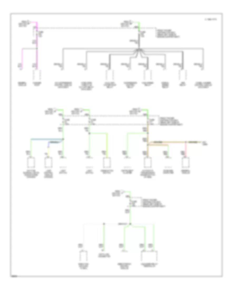
Power Distribution Wiring Diagram (4 of 6) for BMW 535i 1993
 https://portal-diagnostov.com/license.html
Automotive Electricians Portal FZCO
Automotive Electricians Portal FZCO
https://portal-diagnostov.com/license.html
https://portal-diagnostov.com/license.html
Automotive Electricians Portal FZCO
Automotive Electricians Portal FZCOList of elements for Power Distribution Wiring Diagram (4 of 6) for BMW 535i 1993:
- Anti-theft control module
- Blower switch
- C 1995 vftc
- Cd changer
- Central locking trunk lid motor relay
- Double panel power sunroof control module
- Electric power protection relay
- Electric steering column adjustment relay
- From blower relay
- From fusible link
- Front power distribution box (rear left side of engine compartment)
- Fuse f19 30a
- Fuse f27 7.5a
- Fuse f30 10a
- Fuse f32 7.5a
- Fuse f33 7.5a
- Fuse f34 30a
- Fuse f35 30a
- Fuse f36 30a
- Fuse f37 30a
- Fuse f40 7.5a
- Fuse f41 30a
- Fuse f42 30a
- Fuse f43 30a
- Fuse f44 30a
- Hifi amplifier
- Integrated climate regulation control module
- Left door lock motor
- Left door lock switch
- Left seat control switch
- Left seat thigh support switch
- Liftgate lock switch
- Not used
- Radio
- Rear defogger relay
- Rear window washer relay
- Red
- Relay module
- Right door lock motor
- Right door lock switch
- Right seat control switch
- Right seat thigh support switch
- Telephone transceiver
- Trunk lock motor
- W/ thight support only
- Window motor relay
- Wiper relay
Power Distribution Wiring Diagram (5 of 6) for BMW 535i 1993
 https://portal-diagnostov.com/license.html
Automotive Electricians Portal FZCO
Automotive Electricians Portal FZCO
https://portal-diagnostov.com/license.html
https://portal-diagnostov.com/license.html
Automotive Electricians Portal FZCO
Automotive Electricians Portal FZCOList of elements for Power Distribution Wiring Diagram (5 of 6) for BMW 535i 1993:
- 525i/t & 535i only
- Anti-theft control module
- Automatic transmission range switch
- Back-up light switch (m/t)
- Brake light switch
- C 1995 vftc
- Check control module
- Cruise control module
- Cruise control switch
- Electrochromatic rear view mirror
- From ignition switch
- From unloader v relay terminal 15
- From unloader w relay terminal r
- Front power distribution box (rear left side of engine compartment)
- Fuse f1 15a
- Fuse f12 15a
- Fuse f15 7.5a
- Fuse f16 30a
- Fuse f18 15a
- Glove box light
- Instrument cluster
- Jet heater thermoswitch
- Lamp control module
- Left makeup mirror light
- Left rear interior light
- Left seat heater switch
- Left side memory mirror
- Mirror control switch
- On-board computer
- Radio
- Rear window washer relay
- Rear window wiper relay 1
- Rear window wiper relay 2
- Right makeup mirror light
- Right rear interior light
- Right seat heater switch
- Right side memory mirror
- Seat/mirror memory control module
- Telephone interface
- Telephone transceiver
- W/ egs
- W/ memory
- W/ memory only
- W/o egs
- W/o memory
- Wiper relay
Power Distribution Wiring Diagram (6 of 6) for BMW 535i 1993
 https://portal-diagnostov.com/license.html
Automotive Electricians Portal FZCO
Automotive Electricians Portal FZCO
https://portal-diagnostov.com/license.html
https://portal-diagnostov.com/license.html
Automotive Electricians Portal FZCO
Automotive Electricians Portal FZCOList of elements for Power Distribution Wiring Diagram (6 of 6) for BMW 535i 1993:
- A/c compressor control module (m5 & 525i/t)
- Abs relay
- Automatic transmission range switch (w/ egs)
- Auxiliary water pump relay
- C 1995 vftc
- Combination switch
- Compressor control relay
- Data link connector
- Daytime running lights coding diode (canada)
- E-box fan (m5 & 535i w/ eml)
- From ignition switch
- Front power distribution box (rear left side of engine compartment)
- Fuse f17 7.5a
- Fuse f2 7.5a
- Fuse f24 10a
- Fuse f28 15a
- Fuse f29 7.5a
- Fuse f3 7.5a
- General module
- High speed relay
- Instrument cluster
- Lamp control module (canada)
- Light switch
- Normal speed relay
- Not used
- On-board computer
- Servotronic control module
- Unloader relay terminal 61
- Washer pump
- Wheel camber control module (m5 & 525i/t)
- Wide open throttle cut-off relay (m5 & 525i/t)
POWER DOOR LOCKS
Power Door Lock Wiring Diagram (1 of 2) for BMW 535i 1993
 https://portal-diagnostov.com/license.html
Automotive Electricians Portal FZCO
Automotive Electricians Portal FZCO
https://portal-diagnostov.com/license.html
https://portal-diagnostov.com/license.html
Automotive Electricians Portal FZCO
Automotive Electricians Portal FZCOList of elements for Power Door Lock Wiring Diagram (1 of 2) for BMW 535i 1993:
- (below right g303
- (late production)
- Anti-theft control module (alpine)
- Anti-theft control module (right side of i/p)
- Crash control module (front power distribution box)
- Crash information
- Crash signal
- Data line
- Driver's door lock switch
- Electric power control protection relay control
- Electric power protection relay (rear power distribution box)
- Front power distribution box (left rear of engine comp.)
- Fuse f17 7.5a
- Fuse f32 7.5a
- Fuse f33 7.5a
- Fuse f37 30a
- General module (left side of rear seat)
- Hot at all times
- Hot in run and start
- Inertia switch (left side of rear seat)
- Lock front doors signal
- Lock motor signal
- Lock motors control
- Lock motors control (close)
- Lock motors control (open)
- Passenger's door lock motor locked
- Passenger's door lock switch
- Power for electronics
- Power input
- Rear power distribution box (below left side of rear seat)
- Rear seat)
- Red/
- Unlock door lock motors signal passenger's door lock motor locked
- Unlock trunk
- X253
- X255
- X332
- X65
Power Door Lock Wiring Diagram (2 of 2) for BMW 535i 1993
 https://portal-diagnostov.com/license.html
Automotive Electricians Portal FZCO
Automotive Electricians Portal FZCO
https://portal-diagnostov.com/license.html
https://portal-diagnostov.com/license.html
Automotive Electricians Portal FZCO
Automotive Electricians Portal FZCOList of elements for Power Door Lock Wiring Diagram (2 of 2) for BMW 535i 1993:
- (below g303
- (late production)
- Driver's door lock motor
- Gas filler lock motor
- Left rear door lock motor
- Passenger's door lock motor
- Power window system
- Power window system/ power tops system
- Relay module (left side of rear seat)
- Right rear door lock motor
- Right rear seat)
- Trunk lock motor
- X258
- X259
- X311
- X315
POWER MIRRORS
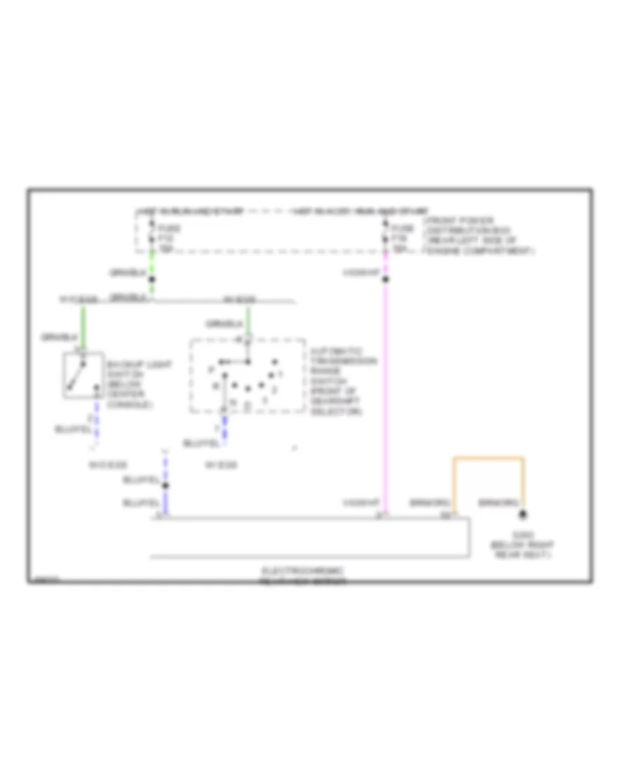
Photochromic Mirror Wiring Diagram for BMW 535i 1993
 https://portal-diagnostov.com/license.html
Automotive Electricians Portal FZCO
Automotive Electricians Portal FZCO
https://portal-diagnostov.com/license.html
https://portal-diagnostov.com/license.html
Automotive Electricians Portal FZCO
Automotive Electricians Portal FZCOList of elements for Photochromic Mirror Wiring Diagram for BMW 535i 1993:
- Automatic transmission range switch (front of gearshift selector)
- Backup light switch (below center console)
- Electrochromic rear view mirror
- Front power distribution box (rear left side of engine compartment)
- Fuse f12 15a
- Fuse f18 15a
- G303 (below right rear seat)
- Hot in accy, run and start
- Hot in run and start
- W/ egs
- W/o egs
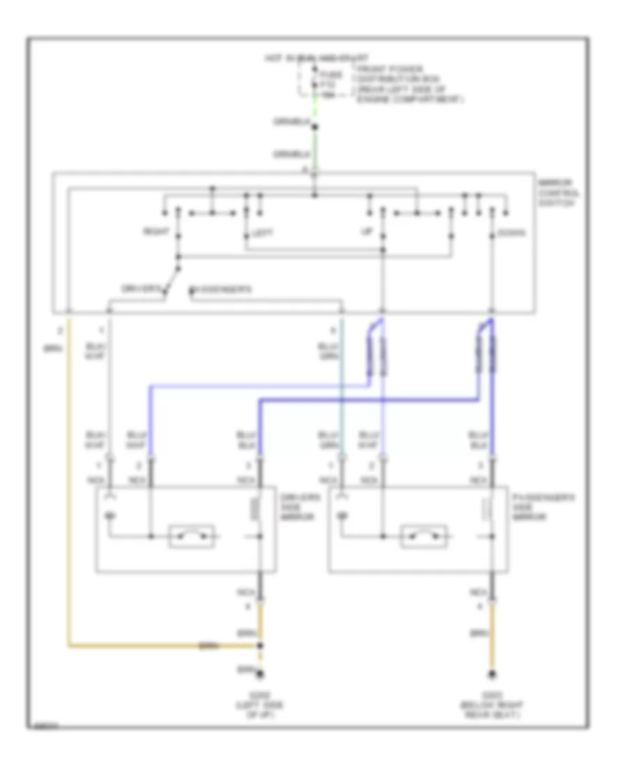
Power Mirror Wiring Diagram for BMW 535i 1993
 https://portal-diagnostov.com/license.html
Automotive Electricians Portal FZCO
Automotive Electricians Portal FZCO
https://portal-diagnostov.com/license.html
https://portal-diagnostov.com/license.html
Automotive Electricians Portal FZCO
Automotive Electricians Portal FZCOList of elements for Power Mirror Wiring Diagram for BMW 535i 1993:
- Down
- Driver's
- Driver's side mirror
- Front power distribution box (rear left side of engine compartment)
- Fuse f12 15a
- G202 (left side of i/p)
- G303 (below right rear seat)
- Hot in run and start
- Left
- Mirror control switch
- Nca
- Passenger's
- Passenger's side mirror
- Right
POWER SEATS
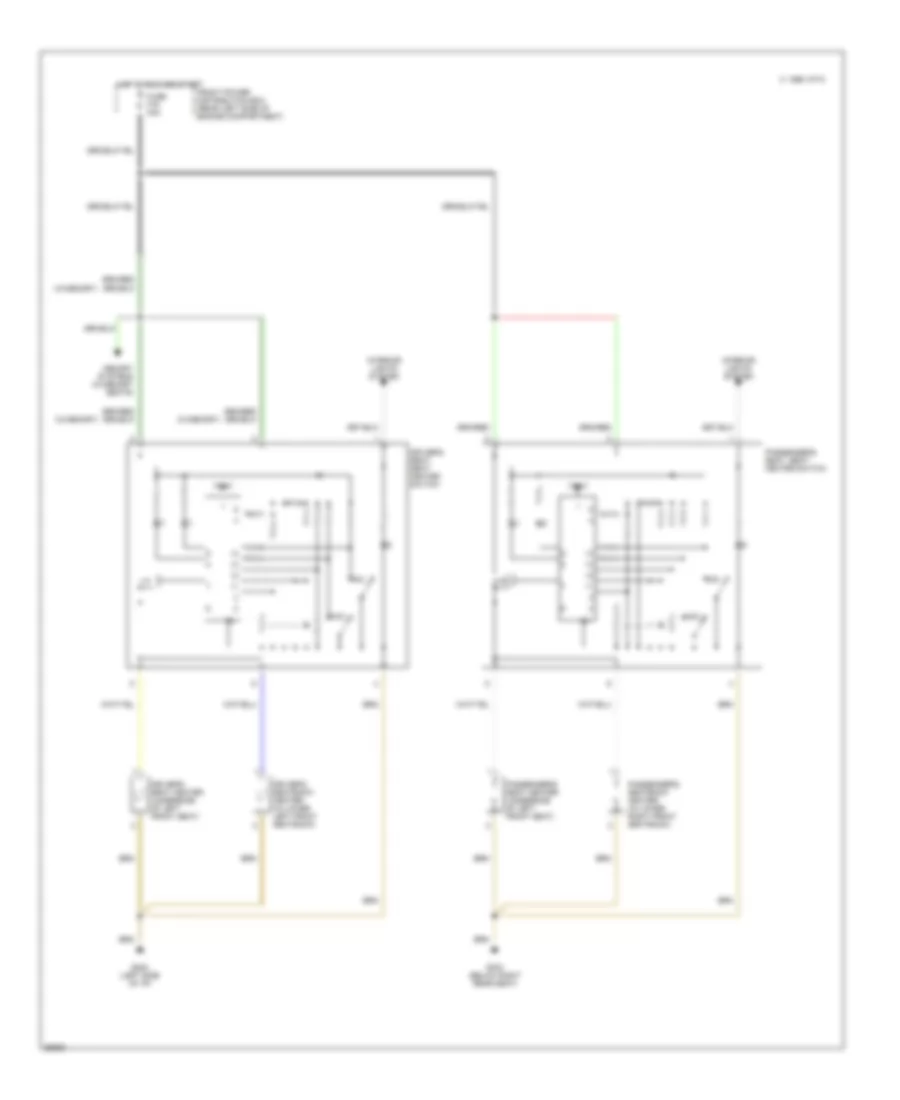
Heated Seats Wiring Diagram for BMW 535i 1993
 https://portal-diagnostov.com/license.html
Automotive Electricians Portal FZCO
Automotive Electricians Portal FZCO
https://portal-diagnostov.com/license.html
https://portal-diagnostov.com/license.html
Automotive Electricians Portal FZCO
Automotive Electricians Portal FZCOList of elements for Heated Seats Wiring Diagram for BMW 535i 1993:
- (w/memory)
- C 1995 vftc
- Driver's seat heater (underside of left front seat)
- Driver's seat, seat heater switch
- Driver's seatback heater (in lower left front seatback)
- Front power distribution box (rear left side of engine compartment)
- Fuse f16 30a
- G202 (left side of i/p)
- G303 (below right rear seat)
- Hot in run and start
- Interior lights system
- Max
- Memory systems (w/memory seats)
- Min
- Passenger's seat heater (underside of left front seat)
- Passenger's seat, seat heater switch
- Passenger's seatback heater (in lower right front seatback)
- Test
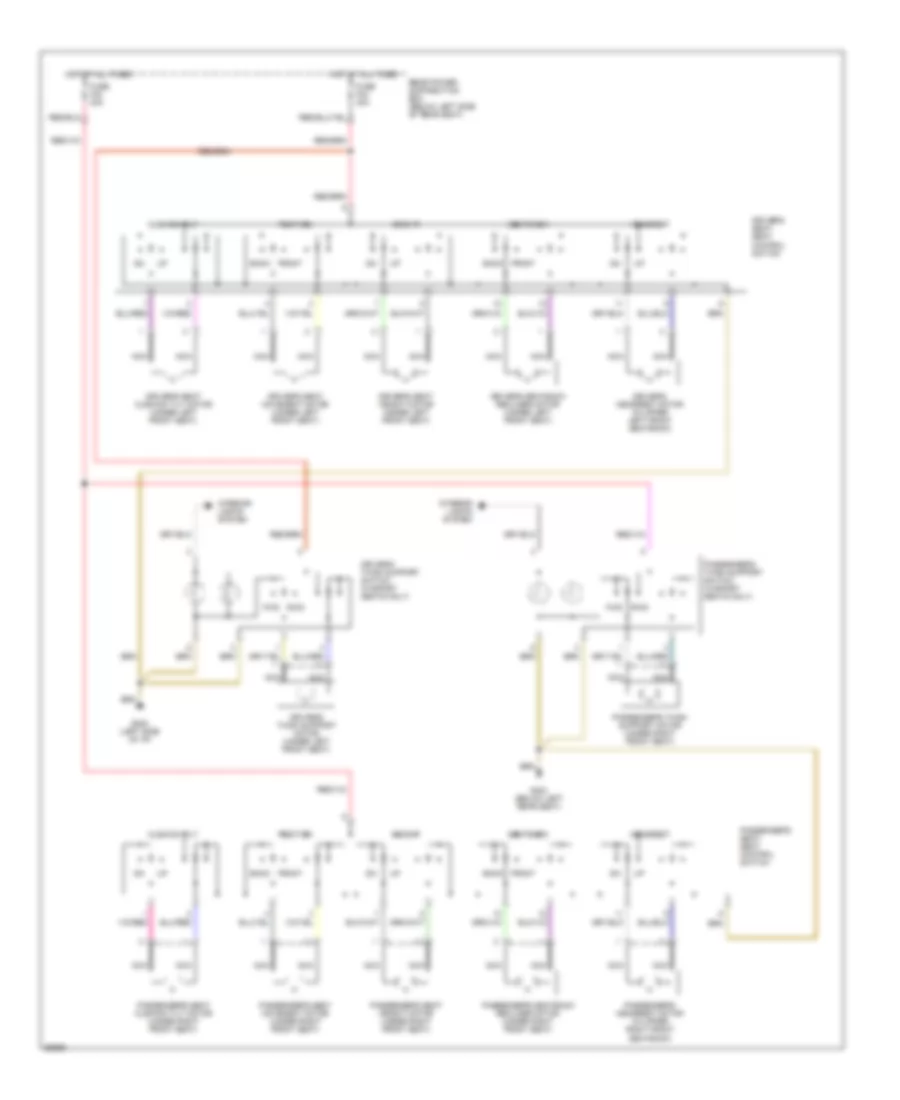
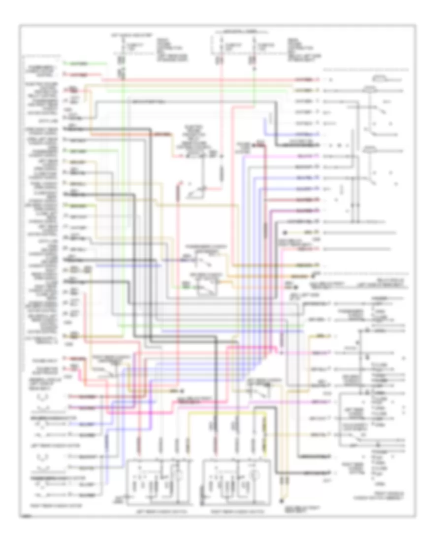
Power Seats Wiring Diagram for BMW 535i 1993
 https://portal-diagnostov.com/license.html
Automotive Electricians Portal FZCO
Automotive Electricians Portal FZCO
https://portal-diagnostov.com/license.html
https://portal-diagnostov.com/license.html
Automotive Electricians Portal FZCO
Automotive Electricians Portal FZCOList of elements for Power Seats Wiring Diagram for BMW 535i 1993:
- Back
- Cushion tilt
- Driver's headrest motor (in upper left front seatback)
- Driver's seat cushion tilt motor (under left front seat)
- Driver's seat height motor (under left front seat)
- Driver's seat movement motor (under left front seat)
- Driver's seat, seat control switch
- Driver's seatback recliner motor (under left front seat)
- Driver's thigh support motor (under left front seat)
- Driver's thigh support switch (w/sport seats only)
- Front
- Fuse f42 30a
- Fuse f43 30a
- Fwd
- G202 (left side of i/p)
- G303 (below left rear seat)
- Headrest
- Height
- Hot at all times
- Interior lights system
- Nca
- Passenger's headrest motor (in upper right front seatback)
- Passenger's seat cushion tilt motor (under right front seat)
- Passenger's seat height motor (under right front seat)
- Passenger's seat movement motor (under right front seat)
- Passenger's seat, seat control switch
- Passenger's seatback recliner motor (under right front seat)
- Passenger's thigh support motor (under right front seat)
- Passenger's thigh support switch (w/sport seats only)
- Position
- Rear power distribution box (below left side of rear seat)
- Rwd
- Seatback
POWER WINDOWS
Power Window Wiring Diagram for BMW 535i 1993
 https://portal-diagnostov.com/license.html
Automotive Electricians Portal FZCO
Automotive Electricians Portal FZCO
https://portal-diagnostov.com/license.html
https://portal-diagnostov.com/license.html
Automotive Electricians Portal FZCO
Automotive Electricians Portal FZCOList of elements for Power Window Wiring Diagram for BMW 535i 1993:
- (below g303
- (below right g303
- (left side g202
- (not used)
- Child safety lock switch
- Close
- Close left rear window signal
- Close off
- Close pass. window signal
- Close right rear window signal
- Close right rear window signal close left rear window signal driver's window motor control
- Data line
- Driver's & left rear window control/ sunroof motor control
- Driver's window limit switch
- Driver's window motor
- Driver's window open signal
- Driver's window switch
- Electric power control protection relay control
- Electric power protection relay (rear power distribution box)
- Front console window switch assembly
- Front power distribution box (left rear side of engine comp.)
- Fuse f17 7.5a
- Fuse f30 7.5a
- Fuse f47 30a
- General module (left side of
- Hot at all times
- Hot in run and start
- Left rear window
- Left rear window motor
- Left rear window motor control
- Left rear window open signal
- Left rear window switch
- Limit switch
- Of i/p)
- Off
- Open
- Open driver's window signal close driver's window signal right rear window open signal
- Open left rear window signal open passenger's window signal
- Open right rear window signal
- Pass. window open signal
- Passenger's and right rear window motor control
- Passenger's window limit switch
- Passenger's window motor
- Passenger's window motor control
- Passenger's window switch
- Power for electronics
- Power input
- Power tops system
- Rear power distribution box (below left side of rear seat)
- Rear seat)
- Red
- Red/
- Relay module (left side of rear seat)
- Right rear seat)
- Right rear window limit switch
- Right rear window motor
- Right rear window switch
- X253
- X254
- X255
- X258
- X259
- X316
- X317
- X332
RADIO
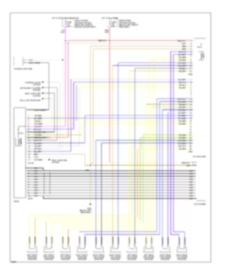
Radio Wiring Diagrams for BMW 535i 1993
 https://portal-diagnostov.com/license.html
Automotive Electricians Portal FZCO
Automotive Electricians Portal FZCO
https://portal-diagnostov.com/license.html
https://portal-diagnostov.com/license.html
Automotive Electricians Portal FZCO
Automotive Electricians Portal FZCOList of elements for Radio Wiring Diagrams for BMW 535i 1993:
- 10a
- 6.3a
- Antenna amplifier
- Body computer system
- Cd changer
- Cellular telephone
- Coax cable
- Front power distribution box (rear left side of engine compartment)
- Fuse f18 15a
- Fuse f36 30a
- G304 (below left rear seat)
- Hifi amplifier
- Hot at all times
- Hot in accy, run and start
- Instrument cluster system
- Interior lights system
- Left front high range speaker
- Left front low range speaker
- Left front midrange speaker
- Left rear high range speaker
- Left rear low range speaker
- Nca
- Power input
- Radio
- Rear power distribution box (below left side of rear seat)
- Right front high range speaker
- Right front low range speaker
- Right front midrange speaker
- Right rear high range speaker
- Right rear low range speaker
- X18126
- X605
- X606
- X8075
STARTING/CHARGING
Charging Wiring Diagram for BMW 535i 1993
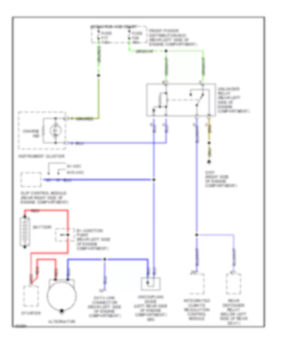 https://portal-diagnostov.com/license.html
Automotive Electricians Portal FZCO
Automotive Electricians Portal FZCO
https://portal-diagnostov.com/license.html
https://portal-diagnostov.com/license.html
Automotive Electricians Portal FZCO
Automotive Electricians Portal FZCOList of elements for Charging Wiring Diagram for BMW 535i 1993:
- Alternator
- B+ junction point (rear left side of engine compartment)
- Battery
- Charge ind
- Data link connector (rear left side of engine compartment)
- Front power distribution box (rear left side of engine compartment)
- Fuse f17 7.5a
- Fuse f28 15a
- G101 (right side of engine compartment)
- Hot in run and start
- Instrument cluster
- Integrated climate regulation control module
- Rear defogger relay (below left side of rear seat)
- Red
- Slip control module (rear right side of engine compartment)
- Starter
- Uncoupling diode (left rear side of engine compartment) (m5)
- Unloader relay (rear left side of engine compartment)
- W/ asc
- W/o asc
Starting Wiring Diagram for BMW 535i 1993
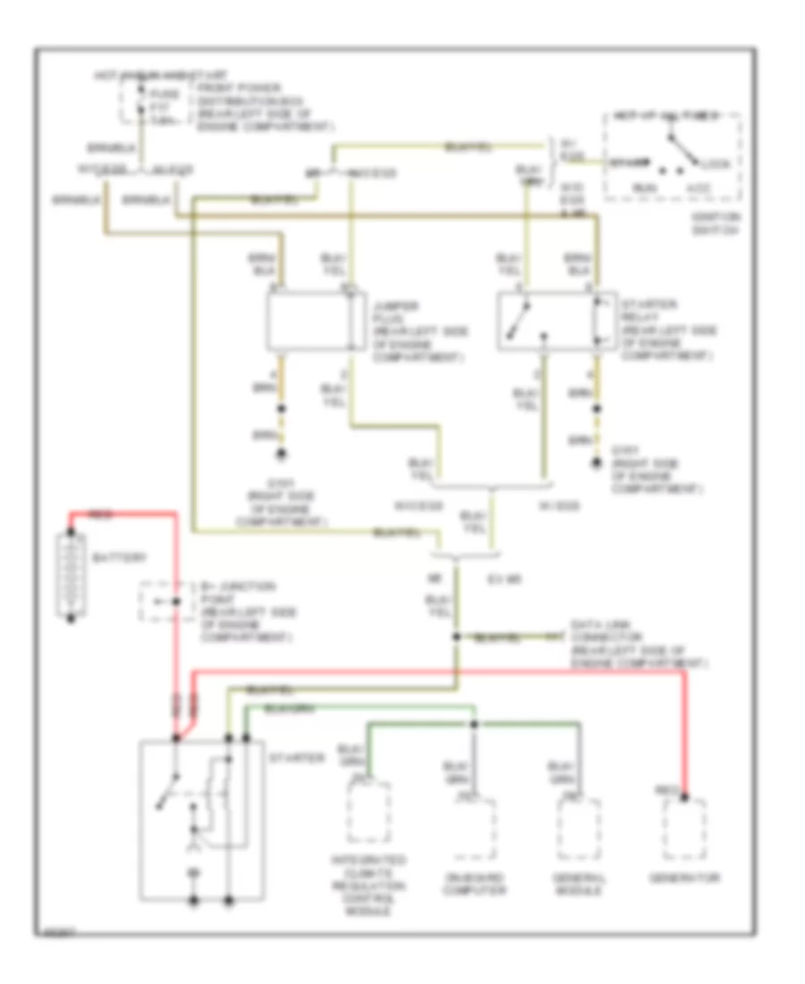 https://portal-diagnostov.com/license.html
Automotive Electricians Portal FZCO
Automotive Electricians Portal FZCO
https://portal-diagnostov.com/license.html
https://portal-diagnostov.com/license.html
Automotive Electricians Portal FZCO
Automotive Electricians Portal FZCOList of elements for Starting Wiring Diagram for BMW 535i 1993:
- Acc
- B+ junction point (rear left side of engine compartment)
- Battery
- Data link connector (rear left side of engine compartment)
- Ex m5
- Front power distribution box (rear left side of engine compartment)
- Fuse f17 7.5a
- G101 (right side of engine compartment)
- General module
- Generator
- Hot at all times
- Hot in run and start
- Ignition switch
- Integrated climate regulation control module
- Jumper plug (rear left side of engine compartment)
- Lock
- On-board computer
- Red
- Run
- Start
- Starter
- Starter relay (rear left side of engine compartment)
- W/ egs
- W/o egs
- W/o egs & m5
TRANSMISSION
Transmission Wiring Diagram for BMW 535i 1993
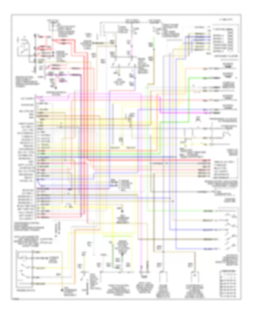 https://portal-diagnostov.com/license.html
Automotive Electricians Portal FZCO
Automotive Electricians Portal FZCO
https://portal-diagnostov.com/license.html
https://portal-diagnostov.com/license.html
Automotive Electricians Portal FZCO
Automotive Electricians Portal FZCOList of elements for Transmission Wiring Diagram for BMW 535i 1993:
- 1995 vftc c
- 87a
- Auto mode sig
- Automatic transmission range switch (front of gearshift selector)
- B+ junction point (right rear side of engine compartment in e-box)
- Bk sw sig
- Bk sw test sig
- Brake light switch (on brake pedal support bracket)
- Check control module
- Ck spd sig tr
- Cruise control module (tempomat) (behind left front of i/p)
- Data link connector (left rear side of engine compartment, right of left side shock tower)
- Drive rng p/n
- Egs 4hp-22
- Eml ctrl sig
- Eng int
- Engine control module (dme) (right rear side of engine compartment in e-box)
- Engine control module relay (right rear side of engine compartment in e-box)
- Engine controls system
- Engine controls system (slip control module) (w/eml)
- Engine controls system (w & w/o eml)
- Engine controls system (w/ & w/o eml)
- Engine controls system (w/eml)
- Fault ind sig.
- Front power distribution box (left rear side of engine compartment)
- Fuel consumption
- Fuse f1 15a
- Fuse f17 7.5a
- G105 (right rear side of engine compartment)
- G202 (left side of i/p)
- G301 (underside of right rear seat)
- Gnd
- Gr rng l1
- Gr rng l2
- Gr rng l3
- Gr rng l4
- Gr rng sig l1
- Gr rng sig l2
- Gr rng sig l3
- Gr rng sig l4
- Hot at all times
- Hot in accy, run & start
- Hot in run & start
- Hyd reg ctrl
- Hydraulic pressure regulator
- Ign timing int
- Instrument cluster
- Interior lights system
- Kick down switch (right side of left footwell)
- Kick-dn sig
- Man mode sig
- Nca
- On-board computer
- Out spd (+)
- Out spd (-)
- Prog sig
- Program switch
- Red
- Relay ctrl
- Rxd data lk
- Set throt sig
- Shift lk ctrl
- Shift lock (below center console front of gearshift selector)
- Sol val 1 ctrl
- Sol val 2 ctrl
- Solenoid valve 1
- Solenoid valve 2
- Solenoid valve 3
- Solenoid valve 5
- Spd sns shd
- Starter relay (left rear side of engine compartment in front power distribution box)
- Tcc sol val
- Term 30 volt sply
- Throttle control module (eml) (right rear side of engine compartment in e-box)
- Throttle position sensor
- Throttle sig
- Ti meas (fl)
- Ti meas sig
- Ti sig (fuel econ.)
- To mechanical linkage
- Trans mode
- Transmission control module (egs) (right rear side of engine compartment in e-box)
- Transmission valve unit (in transmission)
- Txd diag lk
- Volt, tps
- W/ eml
- W/eml
- W/eml only
- W/o eml
- X16
- X502
Transmission Wiring Diagram, 4 Speed with Overdrive for BMW 535i 1993
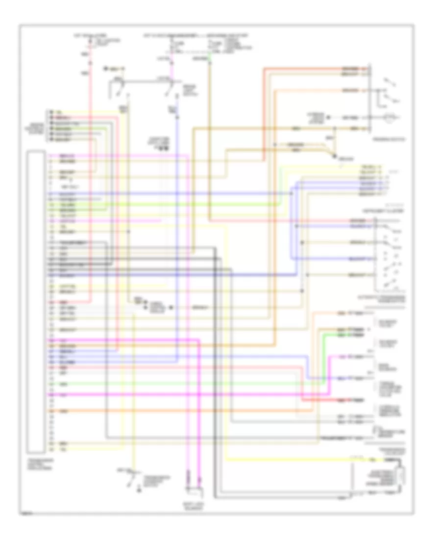 https://portal-diagnostov.com/license.html
Automotive Electricians Portal FZCO
Automotive Electricians Portal FZCO
https://portal-diagnostov.com/license.html
https://portal-diagnostov.com/license.html
Automotive Electricians Portal FZCO
Automotive Electricians Portal FZCOList of elements for Transmission Wiring Diagram, 4 Speed with Overdrive for BMW 535i 1993:
- 1991 only
- Automatic transmission range switch
- B+ junction point
- Band solenoid
- Brake light switch
- Check control module
- Computer data lines system
- Electronic transmission engine speed sensor
- Engine controls system
- Front power distribution box
- Fuse f1 15a
- Fuse f17 7.5a
- Ground
- Hot at all times
- Hot in accy, run and start
- Hot in run and start
- Hydraulic pressure regulator
- Instrument cluster
- Interior lights system
- Nca
- Oil temperature sensor
- Program switch
- Red
- Shift lock solenoid
- Solenoid valve 1
- Solenoid valve 2
- Torque converter clutch sol valve
- Transmission control module (egs)
- Transmission kickdown switch
- Transmission valve unit
- Transparent
WIPER/WASHER
Headlamp/Foglamp Washer Wiring Diagram for BMW 535i 1993
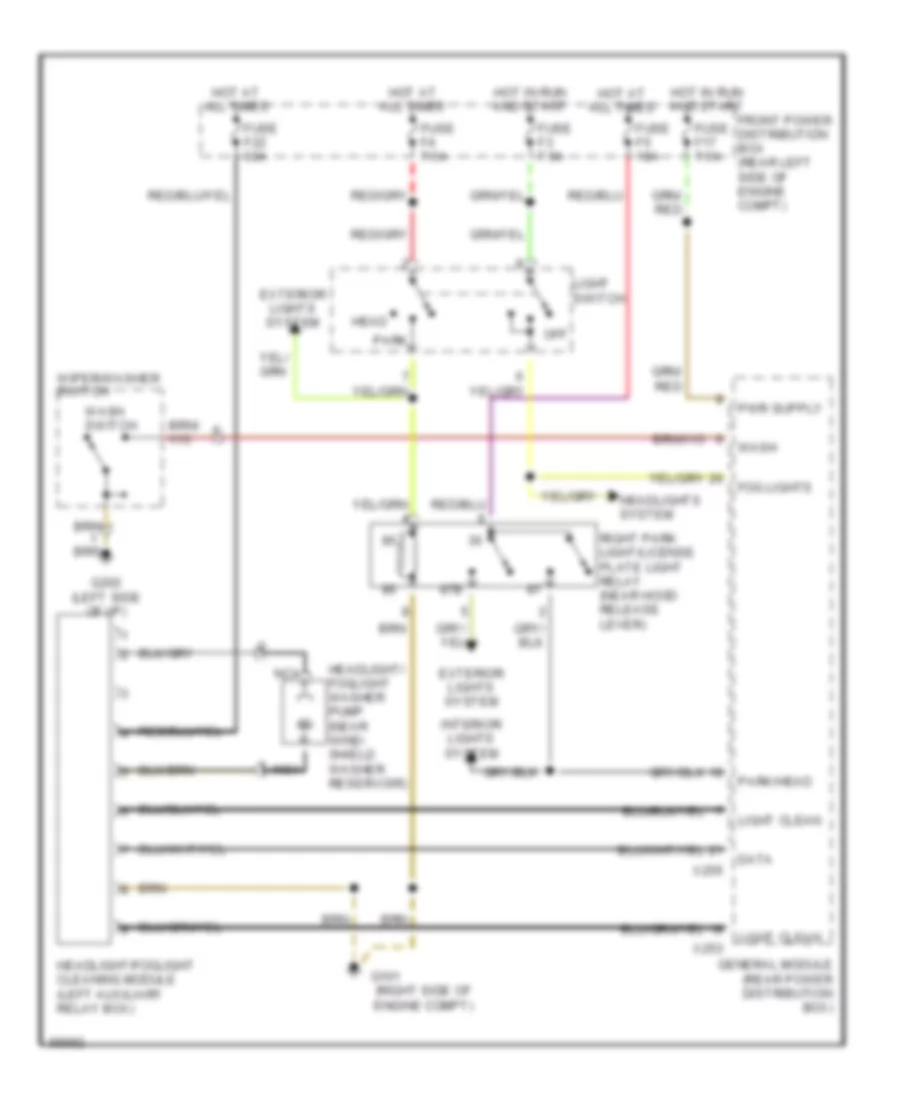 https://portal-diagnostov.com/license.html
Automotive Electricians Portal FZCO
Automotive Electricians Portal FZCO
https://portal-diagnostov.com/license.html
https://portal-diagnostov.com/license.html
Automotive Electricians Portal FZCO
Automotive Electricians Portal FZCOList of elements for Headlamp/Foglamp Washer Wiring Diagram for BMW 535i 1993:
- (right side of engine compt)
- 87b
- Data
- Exterior lights system
- Fog lights
- Front power distribution box (rear left side of engine compt)
- Fuse f17 7.5a
- Fuse f22 30a
- Fuse f3 7.5a
- Fuse f4 7.5a
- Fuse f5 10a
- G101
- G202 (left side of i/p)
- General module (rear power distribution box)
- Head
- Headlight/ foglight washer pump (near wind- shield washer reservoir)
- Headlight/foglight cleaning module (left auxiliary relay box)
- Headlights system
- Hot at all times
- Hot in run and start
- Interior lights system
- Light clean
- Light switch
- Nca
- Off
- Park
- Park/head
- Right park light/license plate light relay (near hood release lever)
- Wash
- Wash switch
- Wiper/washer switch
- X253
- X255
Jet Heater Wiring Diagram for BMW 535i 1993
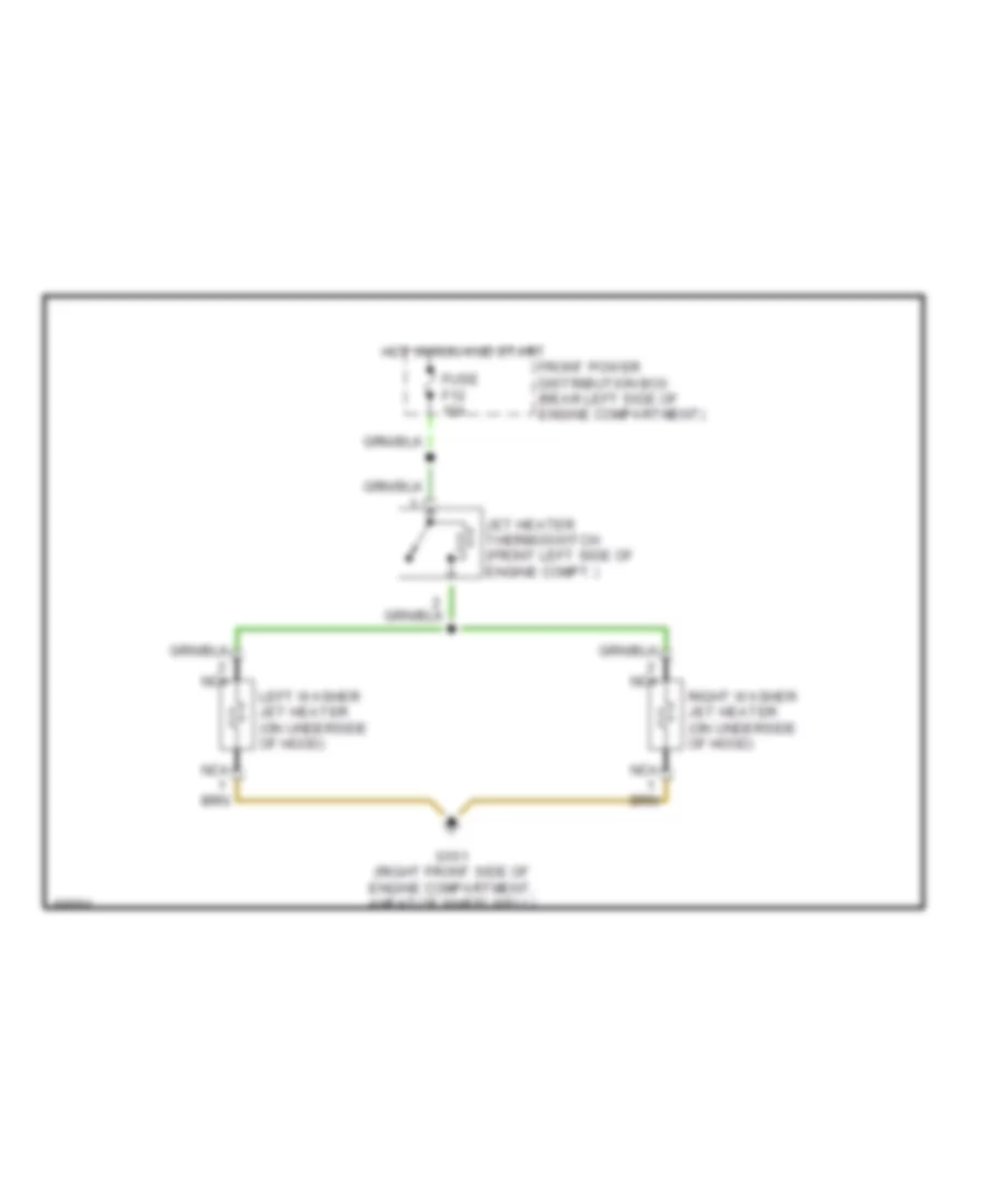 https://portal-diagnostov.com/license.html
Automotive Electricians Portal FZCO
Automotive Electricians Portal FZCO
https://portal-diagnostov.com/license.html
https://portal-diagnostov.com/license.html
Automotive Electricians Portal FZCO
Automotive Electricians Portal FZCOList of elements for Jet Heater Wiring Diagram for BMW 535i 1993:
- Front power distribution box (rear left side of engine compartment)
- Fuse f12 15a
- G101 (right front side of engine compartment, ahead of wheelwell)
- Hot in run and start
- Jet heater thermoswitch (front left side of engine compt.)
- Left washer jet heater (on underside of hood)
- Nca
- Right washer jet heater (on underside of hood)
Wiper/Washer Wiring Diagram for BMW 535i 1993
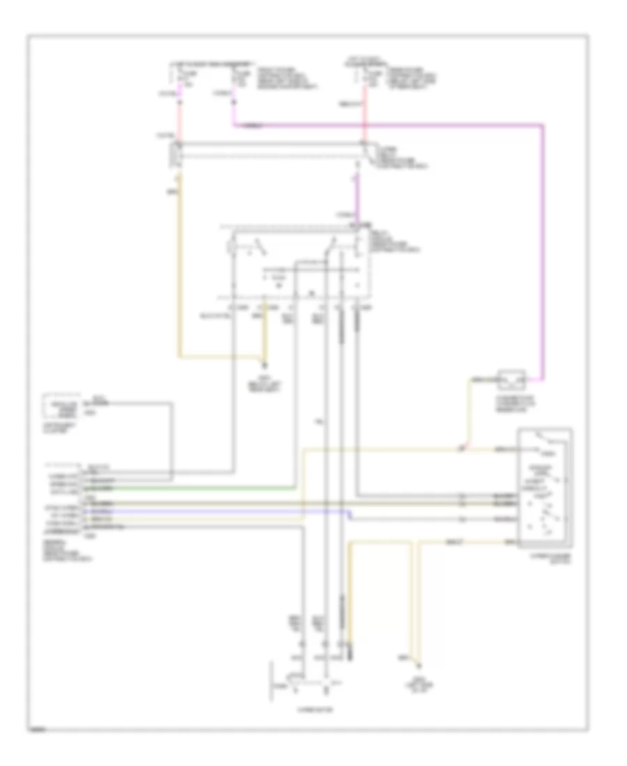 https://portal-diagnostov.com/license.html
Automotive Electricians Portal FZCO
Automotive Electricians Portal FZCO
https://portal-diagnostov.com/license.html
https://portal-diagnostov.com/license.html
Automotive Electricians Portal FZCO
Automotive Electricians Portal FZCOList of elements for Wiper/Washer Wiring Diagram for BMW 535i 1993:
- Data line
- Fast
- Front power distribution box (rear left side of engine compartment)
- Fuse f1 15a
- Fuse f24 10a
- Fuse f34 30a
- G202 (left side of i/p)
- G303 (below left rear seat)
- General module (rear power distribution box)
- Hot in accy, run and start
- Instrument cluster
- Int wiper
- Inter
- Nca
- Normal
- Off
- Park
- Rear power distribution box (below left side of rear seat)
- Relay module (rear power distribution box)
- Run
- Single
- Speed sig
- Stnd wiper
- Vehiclwe speed signal
- Wash
- Wash signl
- Washer pump (washer fluid reservoir)
- Wiper motor
- Wiper mtr
- Wiper relay (rear power distribution box)
- Wiper/washer switch
- Wipers run
- X253
- X255
- X258
- X259
- X502

 Čeština
 Dansk
Dansk Deutsch
 Ελληνικά
 English
 English
 Español
 Suomi
Suomi Français
 Français
 עברית
עברית Hrvatski
 Magyar
 Italiano
 한국어
한국어 Nederlands
 Polski
 Português
 Português
 Română
 Русский
 Slovenčina
 Slovenščina
 Svenska
 Türkçe
 中文 (中国)
