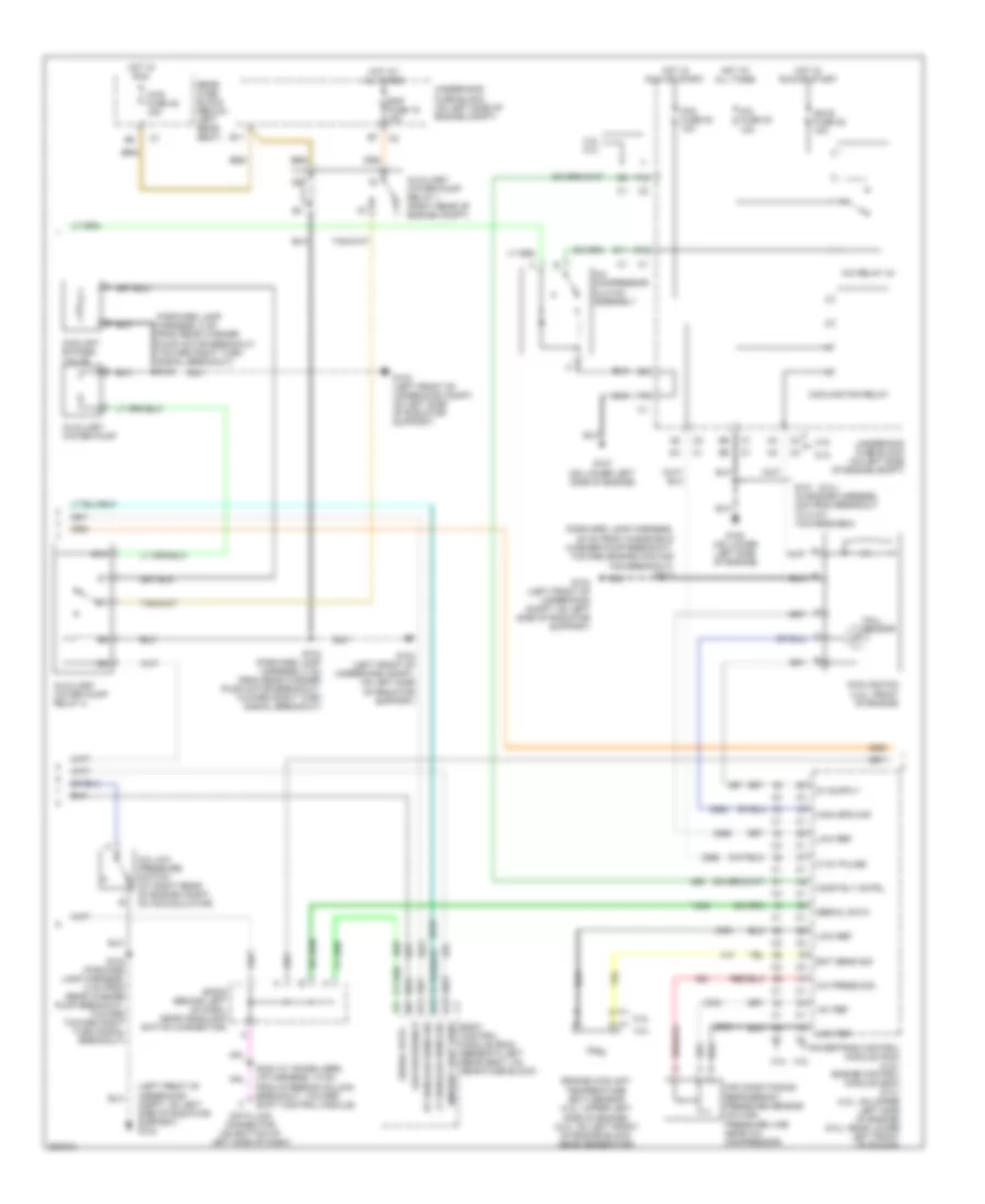
AIR CONDITIONING
Automatic A/C Wiring Diagram, Long Wheel Base (1 of 3) for Chevrolet TrailBlazer 2005
 https://portal-diagnostov.com/license.html
Automotive Electricians Portal FZCO
Automotive Electricians Portal FZCO
https://portal-diagnostov.com/license.html
https://portal-diagnostov.com/license.html
Automotive Electricians Portal FZCO
Automotive Electricians Portal FZCO
List of elements for Automatic A/C Wiring Diagram, Long Wheel Base (1 of 3) for Chevrolet TrailBlazer 2005:
- (i/p harness, 15.5 cm from reci- rculation actuator connector)
- (i/p harness, 16 cm from sp201 breakout, toward dlc) s211
- (i/p harness, 5 cm from mode motor breakout, toward instrument cluster breakout)
- 5v ref
- A/c comp status
- A/c low press sw
- A10
- A11
- A12
- Air temp door ctrl
- Air temp dr pos sig
- Air temperature actuator (left) (behind left center of dash)
- Air temperature actuator (right) (behind right center of dash)
- Ambient air temp sig
- Ambient air temperature sensor (on left center of radiator support)
- Ambient light
- Ambient light/ sun load sensor assembly (on top center of dash, near base of windshield)
- B10
- B11
- B12
- Batt pos volt
- Battery
- Blower fuse 35 40a
- Blower motor (below right side of dash)
- Blower motor control module (lower right side of dash)
- Blwr mtr spd ctrl
- Class 2
- Coolant bypass ctrl
- Def door pos sig
- Defrost actuator (behind upper left center of dash)
- Defrost door ctrl
- G102 (left side of underhood compt, near rear of underhood fuse block)
- G201
- G302 (on lower left "b" pillar)
- Ground
- Hot at all times
- Hot in run
- Hvac control module (center of dash)
- Hvac i fuse 39 10a
- Hvac-b fuse 36 10a
- Ign 3
- Inside air temp ctrl
- Inside air temp sig
- Inside air temperature sensor assembly (at top of left "b" pillar, behind trim)
- Interior lights system
- Left sensor
- Logic
- Low ref
- Low reference
- Lower left air temperature sensor (behind lower left center of dash, on air duct)
- Lower right air temperature sensor (behind lower right side of dash, on air duct)
- Lps dimming ctrl
- Lwr lt air temp sig
- Lwr rt air temp sig
- Mode actuator (behind upper left center of dash)
- Mode door ctrl
- Mode door pos sig
- Nca
- Rear fuse block (below left rear seat)
- Recirc door cntrl
- Recirc dr pos sig
- Recirculation actuator (behind upper right side of dash)
- Red
- Right sensor
- S202 (i/p harness, 16.5 cm from steering column connector breakout, toward dlc breakout)
- S216
- S217
- S271 (i/p harness, 14.5 cm from dash compt, lamp breakout, toward center of dash)
- S302 (5 cm from main harness breakout for c700, toward g302)
- Solid state
- Sp201 (at lower right front of lower console)
- Tan
- Under- hood fuse block (on left side of engine compt)
- Upper left air temperature sensor (behind upper left center of dash)
- Upper right air temperature sensor (behind upper right center of dash)
- Uppr lt air temp sig
- Uppr rt air temp sig
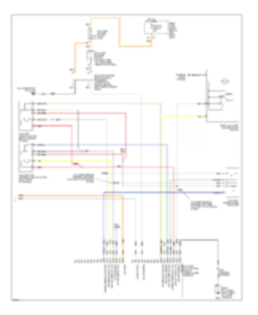
Automatic A/C Wiring Diagram, Long Wheel Base (2 of 3) for Chevrolet TrailBlazer 2005
 https://portal-diagnostov.com/license.html
Automotive Electricians Portal FZCO
Automotive Electricians Portal FZCO
https://portal-diagnostov.com/license.html
https://portal-diagnostov.com/license.html
Automotive Electricians Portal FZCO
Automotive Electricians Portal FZCOList of elements for Automatic A/C Wiring Diagram, Long Wheel Base (2 of 3) for Chevrolet TrailBlazer 2005:
- (5.3l)
- (forward lamp harness, 20 cm from windshield washer pump breakout, toward engine cooling fan breakout) s113
- (forward lamp harness, 8 cm from rear washer pump motor breakout, toward right turn signal breakout) s103
- (left front of underhood compt, on left side of radiator support) g103
- +5v ref
- 0-12v pulse
- 4.2l
- 4.2l 5.3l
- 4wd fuse 48 15a
- 5.3l
- 5.3l 4.2l
- 87a
- A/c compressor clutch assembly
- A/c fuse 30 10a
- A/c low pressure switch (at right rear of engine compt, on accumulator)
- A/c press sig
- A/c relay 44
- A12
- Air conditioning refrigerant pressure sensor (on high pressure line near a/c compressor)
- Ambient light sens
- Auxiliary water pump
- Auxiliary water pump relay 1 (right rear of engine compt)
- Auxiliary water pump relay 2
- B11
- B12
- Body control module (bcm) (beneath left rear seat, on rear fuse block)
- Comp rly cntrl
- Coolant bypass valve
- Cooling fan (4.2l: front of engine)
- Cooling fan relay
- D11
- Data link connector (on bottom of left side of dash)
- E12
- Eap fuse 15 15a
- Ect sens sig
- Engine coolant temperature (ect) sensor (4.2l: upper left side of engine) (5.3l: on left front of engine block, near generator)
- F12
- Fan fuse 20 10a
- G103 (left front of underhood compt, on left side of radiator support)
- G107 (on lower left side of engine)
- G108 (on lower left side of engine)
- Hall sensor
- High spd maf
- Hot at all times
- Hot in run
- Hot in run or start
- Ign e fuse 22 10a
- Low ref
- Low reference
- Lt sunload sens sig
- Powertrain control module (pcm) (4.2l) engine control module (ecm) (5.3l) (4.2l: on upper left side of engine) (5.3l: near lower left front of engine)
- Rear fuse block (below left rear seat)
- Rt sunload sens sig
- S101 (in engine harness, 4cm from breakout to c107, towards ecm)
- S103 (forward lamp harness, 8 cm from rear washer pump breakout, toward toward right turn signal breakout)
- S103 (forward lamp harness, 8 cm from rear washer pump motor breakout, toward right turn signal breakout)
- S232 (w/ immobilizer) (i/p harness, 10 cm from steering column breakout, toward shift control module)
- Serial data
- Sp205 (behind left of dash, near headlamp switch connector)
- Underhood fuse block (on left side of engine compt)
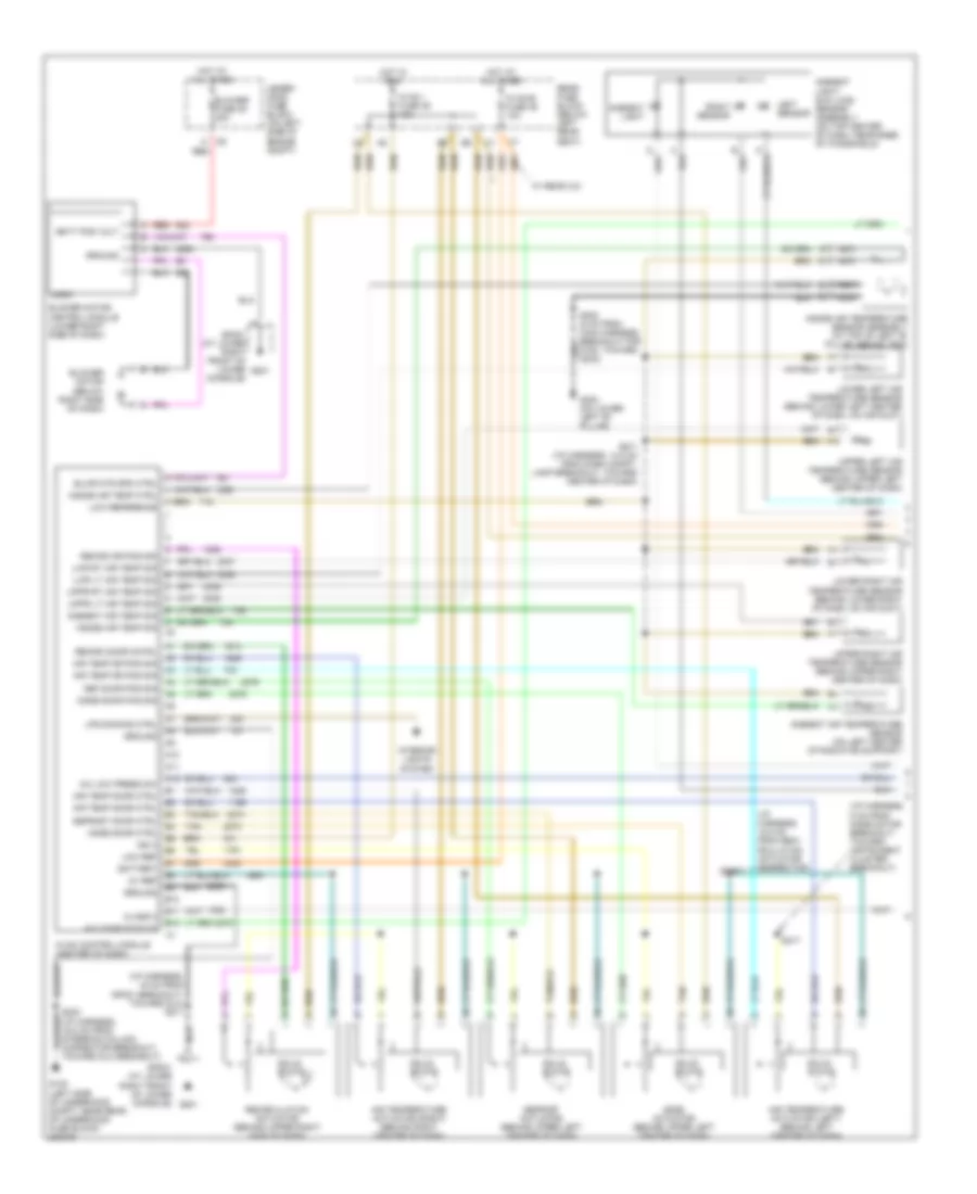
Automatic A/C Wiring Diagram, Long Wheel Base (3 of 3) for Chevrolet TrailBlazer 2005
 https://portal-diagnostov.com/license.html
Automotive Electricians Portal FZCO
Automotive Electricians Portal FZCO
https://portal-diagnostov.com/license.html
https://portal-diagnostov.com/license.html
Automotive Electricians Portal FZCO
Automotive Electricians Portal FZCOList of elements for Automatic A/C Wiring Diagram, Long Wheel Base (3 of 3) for Chevrolet TrailBlazer 2005:
- (in lower console harness, between auxiliary hvac module & c309)
- (in lower console harness, between auxiliary hvac module) & c309)
- (not used)
- (on lower right "d" pillar) g402
- 30a
- 5v reference
- A10
- A11
- A12
- A13
- A14
- A15
- A16
- Auc hvac enable
- Aux act door ctlr
- Aux air temp dr ctlr
- Aux air temp dr pos
- Aux blwr mtr
- Aux mode door ctrl
- Aux mode dr pos sig
- Auxiliary air temperature actuator (right rear of vehicle)
- Auxiliary blower motor (on right side of cargo area, behind trim panel)
- Auxiliary blower motor control processor (in rear hvac module, behind right rear interior panel)
- Auxiliary blower motor fuse
- Auxiliary console mode actuator
- Auxiliary mode actuator (below center of dash)
- B10
- B11
- B12
- B13
- B14
- B15
- B16
- Battery
- Class 2 data
- Console mode dr ctrl
- Console mode dr pos sig
- Front auxiliary blower motor switch
- G201
- Ground auxiliary hvac control module (under lower console)
- Hot at all times
- Interior lights system
- Low reference
- Off
- Rear
- Rear fuse block (below left rear seat)
- Red
- Rr hvac fuse 13 30a
- S307 (console harness)
- S324
- S325
- S326
- S402
- Sp201 (at lower right front of lower console)
- Txv solenoid ctrl
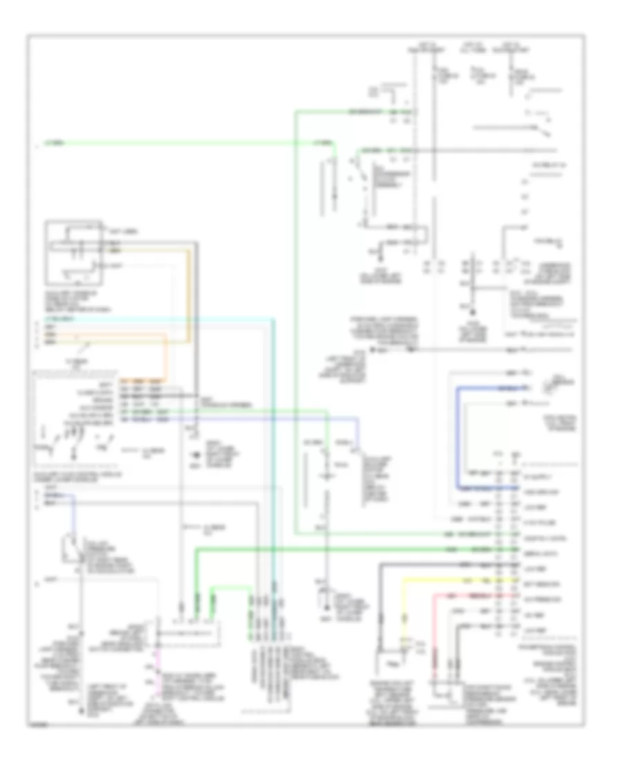
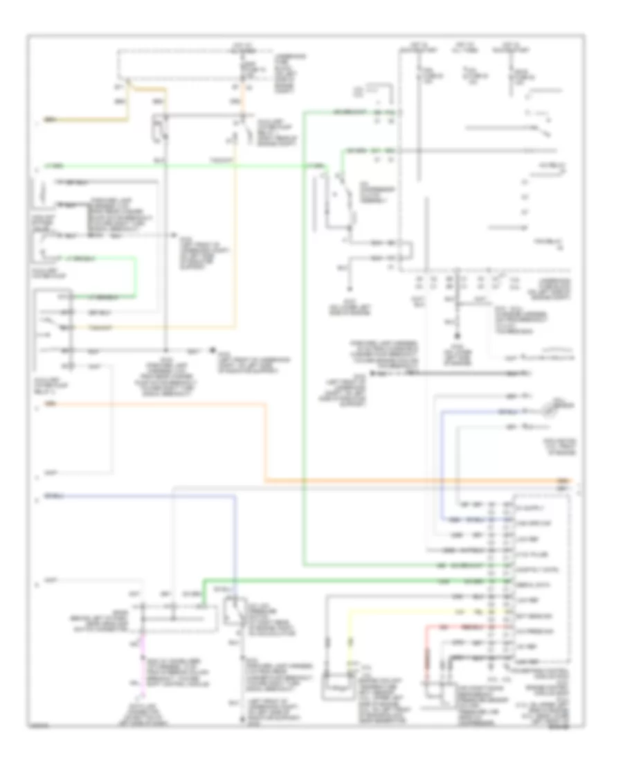
Automatic A/C Wiring Diagram, Short Wheel Base (1 of 2) for Chevrolet TrailBlazer 2005
 https://portal-diagnostov.com/license.html
Automotive Electricians Portal FZCO
Automotive Electricians Portal FZCO
https://portal-diagnostov.com/license.html
https://portal-diagnostov.com/license.html
Automotive Electricians Portal FZCO
Automotive Electricians Portal FZCOList of elements for Automatic A/C Wiring Diagram, Short Wheel Base (1 of 2) for Chevrolet TrailBlazer 2005:
- (i/p harness, 15.5 cm from reci- rculation actuator connector)
- (i/p harness, 16 cm from sp201 breakout, toward dlc) s211
- (i/p harness, 5 cm from mode motor breakout, toward instrument cluster breakout)
- 5v ref
- A/c comp status
- A/c low press sw
- A10
- A11
- A12
- Air temp door ctrl
- Air temp dr pos sig
- Air temperature actuator (left) (behind left center of dash)
- Air temperature actuator (right) (behind right center of dash)
- Ambient air temp sig
- Ambient air temperature sensor (on left center of radiator support)
- Ambient light
- Ambient light/ sun load sensor assembly (on top center of dash, near base of windshield)
- B10
- B11
- B12
- Batt pos volt
- Battery
- Blower fuse 35 40a
- Blower motor (below right side of dash)
- Blower motor control module (lower right side of dash)
- Blwr mtr spd ctrl
- Class 2
- Def door pos sig
- Defrost actuator (behind upper left center of dash)
- Defrost door ctrl
- G102 (left side of underhood compt, near rear of underhood fuse block)
- G201
- G302 (on lower left "b" pillar)
- Ground
- Hot at all times
- Hot in run
- Hvac control module (center of dash)
- Hvac i fuse 39 10a
- Hvac-b fuse 36 10a
- Ign 3
- Inside air temp ctrl
- Inside air temp sig
- Inside air temperature sensor assembly (at top of left "b" pillar, behind trim)
- Interior lights system
- Left sensor
- Logic
- Low ref
- Low reference
- Lower left air temperature sensor (behind lower left center of dash, on air duct)
- Lower right air temperature sensor (behind lower right of dash, on air duct)
- Lps dimming ctrl
- Lwr lt air temp sig
- Lwr rt air temp sig
- Mode actuator (behind upper left center of dash)
- Mode door ctrl
- Mode door pos sig
- Nca
- Rear fuse block (below left rear seat)
- Recirc door cntrl
- Recirc dr pos sig
- Recirculation actuator (behind upper right side of dash)
- Red
- Right sensor
- S216
- S217
- S271 (i/p harness, 14.5 cm from dash compt, lamp breakout, toward center of dash)
- Solid state
- Sp201 (at lower right front of lower console)
- Tan
- Toward dlc breakout)
- Under- hood fuse block (on left side of engine compt)
- Upper left air temperature sensor (behind upper left center of dash)
- Upper right air temperature sensor (behind upper right center of dash)
- Uppr lt air temp sig
- Uppr rt air temp sig
- W/ rear a/c
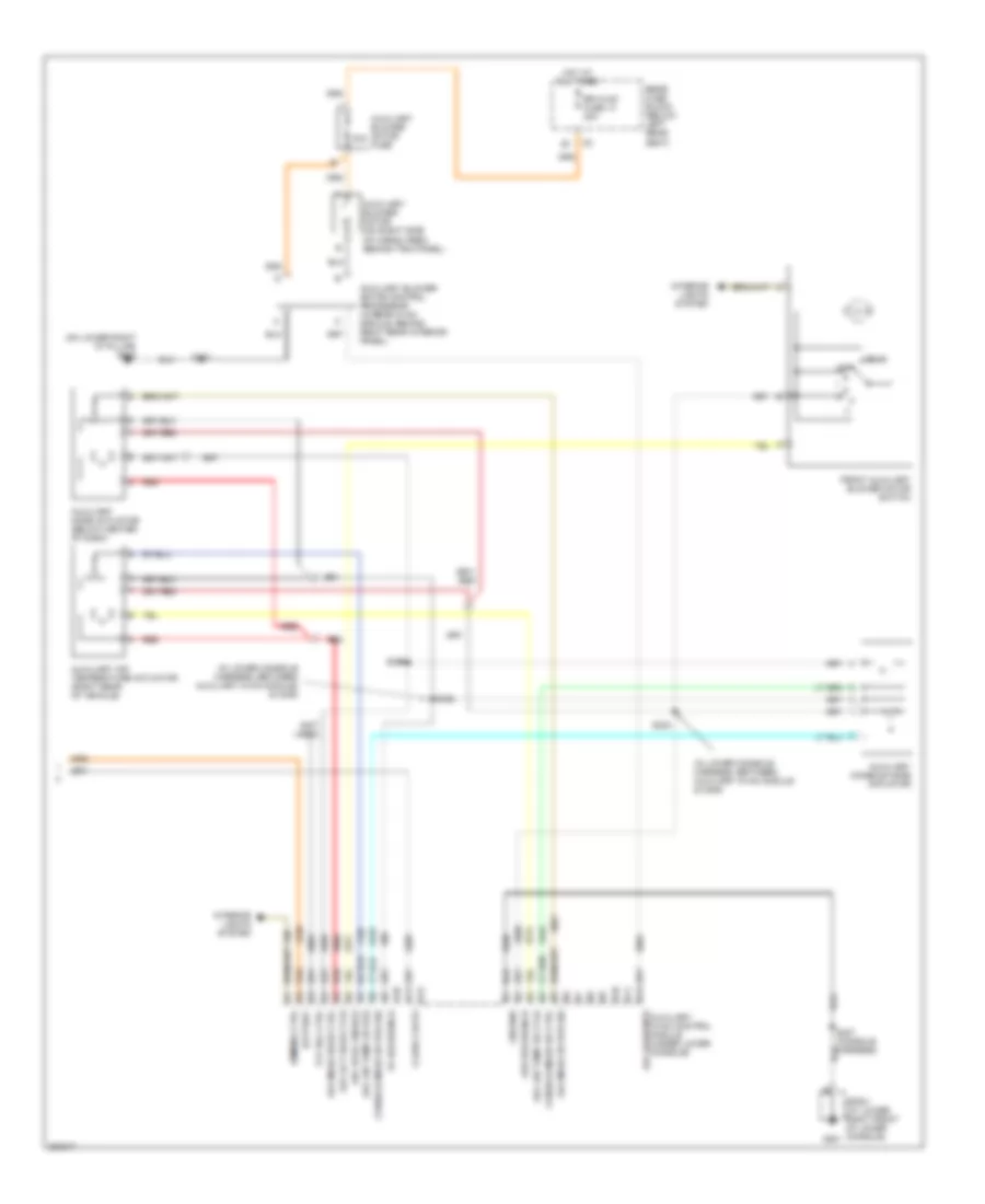
Automatic A/C Wiring Diagram, Short Wheel Base (2 of 2) for Chevrolet TrailBlazer 2005
 https://portal-diagnostov.com/license.html
Automotive Electricians Portal FZCO
Automotive Electricians Portal FZCO
https://portal-diagnostov.com/license.html
https://portal-diagnostov.com/license.html
Automotive Electricians Portal FZCO
Automotive Electricians Portal FZCOList of elements for Automatic A/C Wiring Diagram, Short Wheel Base (2 of 2) for Chevrolet TrailBlazer 2005:
- (5.3l)
- (forward lamp harness, 20 cm from windshield washer pump breakout, toward engine cooling fan breakout) s113
- (left front of underhood compt, on left side of radiator support) g103
- (not used)
- +5v ref
- 0-12v pulse
- 4.2l
- 4.2l 5.3l
- 5.3l
- A/c compressor clutch assembly
- A/c fuse 30 10a
- A/c low pressure switch (at right rear of engine compt, on accumulator)
- A/c press sig
- A/c relay 44
- A12
- Air conditioning refrigerant pressure sensor (on high pressure line near a/c compressor)
- Ambient light sens
- Aux blwr hi spd
- Aux blwr med spd
- Aux mode dr
- Auxiliary blower motor (w/ rear a/c) (below center of dash)
- Auxiliary console mode actuator (w/ rear a/c) (below center of dash)
- Auxiliary hvac control module (under lower console)
- B11
- B12
- Batt
- Body control module (bcm) (beneath left rear seat, on rear fuse block)
- Class 2 data
- Comp rly cntrl
- Cooling fan (4.2l: front of engine)
- D11
- Data link connector (on bottom of left side of dash)
- E12
- Ect sens sig
- Engine coolant temperature (ect) sensor (4.2l: upper left side of engine) (5.3l: on left front of engine block, near generator)
- F12
- Fan fuse 20 10a
- Fan relay
- G103 (left front of underhood compt, on left side of radiator support)
- G107 (on lower left side of engine)
- G108 (on lower left side of engine)
- G201
- Ground
- Hall sensor
- High spd maf
- Hot at all times
- Hot in run or start
- Ign e fuse 22 10a
- Low ref
- Low reference
- Lt sunload sens sig
- Mode
- Off
- Powertrain control module (pcm) (4.2l) engine control module (ecm) (5.3l) (4.2l: on upper left side of engine) (5.3l: near lower left front of engine)
- Rt sunload sens sig
- S101 (in engine harness, 4cm from breakout to c107, towards ecm)
- S103 (forward lamp harness, 8 cm from rear washer pump breakout, toward toward right turn signal breakout)
- S232 (w/ immobilizer) (i/p harness, 10 cm from steering column breakout, toward shift control module)
- S307 (console harness)
- Serial data
- Sp201 (at lower right front of lower console)
- Sp205 (behind left of dash, near headlamp switch connector)
- Underhood fuse block (on left side of engine compt)
- W/ rear a/c
Compressor Wiring Diagram for Chevrolet TrailBlazer 2005
 https://portal-diagnostov.com/license.html
Automotive Electricians Portal FZCO
Automotive Electricians Portal FZCO
https://portal-diagnostov.com/license.html
https://portal-diagnostov.com/license.html
Automotive Electricians Portal FZCO
Automotive Electricians Portal FZCOList of elements for Compressor Wiring Diagram for Chevrolet TrailBlazer 2005:
- (i/p harness, 10 cm from steering column breakout, toward shift control module) (w/ immobilizer) s232
- (left front of underhood compt, on left side of radiator support) g103
- +5v ref
- 4.2l 5.3l
- 5.3l 4.2l
- A/c compressor clutch assembly
- A/c comp status
- A/c fuse 30 10a
- A/c low press sw
- A/c low pressure switch (at right rear of engine compt, on accumulator)
- A/c press sig
- A/c relay 44
- A12
- Air conditioning refrigerant pressure sensor (on high pressure line near a/c compressor)
- B11
- B12
- Class 2
- Comp rly cntrl
- D11
- Data link connector (on bottom left side of dash)
- E12
- F12
- G102 (left side of underhood compt, near rear of underhood fuse block)
- G107 (on lower left side of engine)
- G201
- Ground
- Hot at all times
- Hot in run
- Hot in run or start
- Hvac 1 fuse 39 10a
- Hvac control module (center of dash)
- Hvac-b fuse 36 10a
- Ign 3
- Ign e fuse 22 10a
- Low ref
- Power
- Powertrain control module (pcm) (4.2l) engine control module (ecm) (5.3l) (4.2l: on upper left side of engine) (5.3l: near lower left front of engine)
- Rear fuse block (below left rear seat)
- S103 (forword lamp harness, 8 cm from rear washer pump breakout, toward right turn signal breakout)
- S202 (i/p harness, 16.5 cm from steering column connector breakout, toward dlc breakout)
- S211 (i/p harness, 16 cm from sp201 breakout, toward dlc)
- Serial data
- Sp201 (at lower right front of lower console)
- Sp205 (behind left of dash, near headlamp switch connector)
- Underhood fuse block (on left side of engine compt)
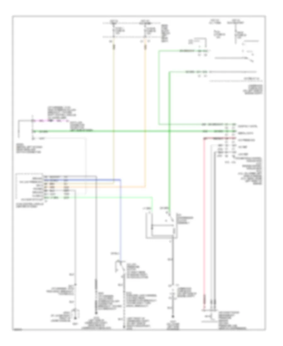
Manual A/C Wiring Diagram, Long Wheel Base (1 of 3) for Chevrolet TrailBlazer 2005
 https://portal-diagnostov.com/license.html
Automotive Electricians Portal FZCO
Automotive Electricians Portal FZCO
https://portal-diagnostov.com/license.html
https://portal-diagnostov.com/license.html
Automotive Electricians Portal FZCO
Automotive Electricians Portal FZCOList of elements for Manual A/C Wiring Diagram, Long Wheel Base (1 of 3) for Chevrolet TrailBlazer 2005:
- (below right side of dash) blower motor resistor assembly
- (i/p harness, 15.5 cm from reci- rculation actuator connector)
- (i/p harness, 16 cm from sp201 breakout, toward dlc) s211
- (i/p harness, 5 cm from mode motor breakout, toward instrument cluster breakout)
- (in the i/p harness, 4 cm from breakout to inflatable restraint i/p module toward blower motor resistor assembly)
- (not used)
- 4wd fuse 48 15a
- 5v ref
- A/c comp status
- A/c low press sw
- A10
- A11
- A12
- Air temp door ctrl
- Air temp dr pos sig
- Air temperature actuator (left) (behind left center of dash)
- Air temperature actuator (right) (behind right center of dash)
- B10
- B11
- B12
- Battery
- Blower fuse 35 40a
- Blower motor (below right side of dash)
- Blower motor relay
- Class 2
- Cool by pass sol ctrl
- Def door pos sig
- Defrost actuator (behind upper left center of dash)
- Defrost door ctrl
- G102 (left side of underhood compt, near rear of underhood fuse block)
- G201
- Ground
- High
- Hot at all times
- Hot in run
- Hvac control module (center of dash)
- Hvac fuse 44 30a
- Hvac i fuse 39 10a
- Hvac-b fuse 36 10a
- Ign 3
- Interior lights system
- Low
- Low ref
- Lps dimming ctrl
- Med1
- Med2
- Med3
- Mode actuator (behind upper left center of dash)
- Mode door ctrl
- Mode door pos sig
- Off
- Off blwr mtr cntrl
- Rear fuse block (below left rear seat)
- Recirc door cntrl
- Recirculation actuator (behind upper right side of dash)
- Red
- S201
- S202 (i/p harness, 16.5 cm from steering column connector breakout, toward dlc breakout)
- S216
- S217
- S250
- Solid state
- Sp201 (at lower right front of lower console)
- Tan
- Under- hood fuse block (on left side of engine compt)
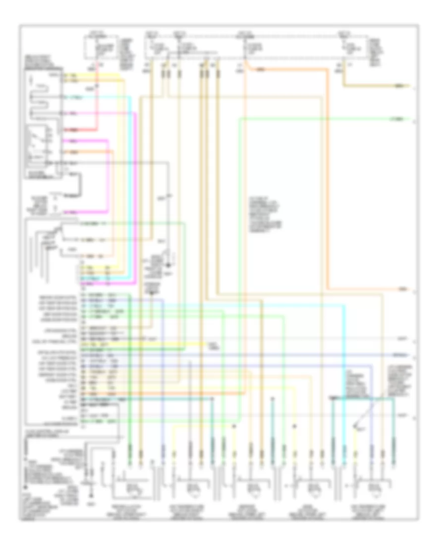
Manual A/C Wiring Diagram, Long Wheel Base (2 of 3) for Chevrolet TrailBlazer 2005
 https://portal-diagnostov.com/license.html
Automotive Electricians Portal FZCO
Automotive Electricians Portal FZCO
https://portal-diagnostov.com/license.html
https://portal-diagnostov.com/license.html
Automotive Electricians Portal FZCO
Automotive Electricians Portal FZCOList of elements for Manual A/C Wiring Diagram, Long Wheel Base (2 of 3) for Chevrolet TrailBlazer 2005:
- (5.3l)
- (forward lamp harness, 20 cm from windshield washer pump breakout, toward engine cooling fan breakout) s113
- (forward lamp harness, 8 cm from rear washer pump motor breakout, toward right turn signal breakout) s103
- (left front of underhood compt, on left side of radiator support) g103
- +5v ref
- 0-12v pulse
- 4.2l
- 4.2l 5.3l
- 5.3l
- 5.3l 4.2l
- 87a
- A/c compressor clutch assembly
- A/c fuse 30 10a
- A/c low pressure switch (at right rear of engine compt, on accumulator)
- A/c press sig
- A/c relay
- Air conditioning refrigerant pressure sensor (on high pressure line near a/c compressor)
- Auxiliary water pump
- Auxiliary water pump relay 1 (right rear of engine compt)
- Auxiliary water pump relay 2
- B11
- Comp rly cntrl
- Coolant bypass valve
- Cooling fan (4.2l: front of engine)
- D11
- Data link connector (on bottom of left side of dash)
- E12
- Eap fuse 15 15a
- Ect sens sig
- Engine coolant temperature (ect) sensor (4.2l: upper left side of engine) (5.3l: on left front of engine block, near generator)
- F12
- Fan fuse 20 10a
- Fan relay
- G103 (left front of underhood compt, on left side of radiator support)
- G107 (on lower left side of engine)
- G108 (on lower left side of engine)
- Hall sensor
- High spd maf
- Hot at all times
- Hot in run or start
- Ign e fuse 22 10a
- Low ref
- Powertrain control module (pcm) (4.2l) engine control module (ecm) (5.3l) (4.2l: on upper left side of engine) (5.3l: near lower left front of engine)
- S101 (in engine harness, 4cm from breakout to c107, towards ecm)
- S103 (forward lamp harness, 8 cm from rear washer pump breakout, toward right turn signal breakout)
- S103 (forward lamp harness, 8 cm from rear washer pump motor breakout, toward right turn signal breakout)
- S232 (w/ immobilizer) (i/p harness, 10 cm from steering column breakout, toward shift control module)
- Serial data
- Sp205 (behind left of dash, near headlamp switch connector)
- Underhood fuse block (on left side of engine compt)
Manual A/C Wiring Diagram, Long Wheel Base (3 of 3) for Chevrolet TrailBlazer 2005
 https://portal-diagnostov.com/license.html
Automotive Electricians Portal FZCO
Automotive Electricians Portal FZCO
https://portal-diagnostov.com/license.html
https://portal-diagnostov.com/license.html
Automotive Electricians Portal FZCO
Automotive Electricians Portal FZCOList of elements for Manual A/C Wiring Diagram, Long Wheel Base (3 of 3) for Chevrolet TrailBlazer 2005:
- (in lower console harness, between auxiliary hvac module & c309)
- (in lower console harness, between auxiliary hvac module) & c309)
- (not used)
- (on lower right "d" pillar) g402
- 30a
- 5v reference
- A10
- A11
- A12
- Auc hvac enable
- Aux act door ctlr
- Aux air temp dr ctlr
- Aux air temp dr pos
- Aux blwr mtr auxiliary hvac control module (under lower console)
- Aux mode door ctrl
- Aux mode dr pos sig
- Auxiliary air temperature actuator (right rear of vehicle)
- Auxiliary blower motor (on right side of cargo area, behind trim panel)
- Auxiliary blower motor control processor (in rear hvac module, behind right rear interior panel)
- Auxiliary blower motor fuse
- Auxiliary console mode actuator
- Auxiliary mode actuator (below center of dash)
- B10
- B11
- B12
- Battery
- Class 2 data
- Console mode dr ctrl
- Console mode dr pos sig
- Dimming ctrl
- Front auxiliary blower motor switch
- G201
- Ground
- Hot at all times
- Interior lights system
- Low reference
- Off
- Rear
- Rear fuse block (below left rear seat)
- Red
- Rr hvac fuse 13 30a
- S307 (console harness)
- S324
- S325
- S326
- S402
- Sp201 (at lower right front of lower console)
- Txv sol ctrl
Manual A/C Wiring Diagram, Short Wheel Base (1 of 2) for Chevrolet TrailBlazer 2005
 https://portal-diagnostov.com/license.html
Automotive Electricians Portal FZCO
Automotive Electricians Portal FZCO
https://portal-diagnostov.com/license.html
https://portal-diagnostov.com/license.html
Automotive Electricians Portal FZCO
Automotive Electricians Portal FZCOList of elements for Manual A/C Wiring Diagram, Short Wheel Base (1 of 2) for Chevrolet TrailBlazer 2005:
- (below right side of dash) blower motor resistor assembly
- (i/p harness, 15.5 cm from reci- rculation actuator connector)
- (i/p harness, 16 cm from sp201 breakout, toward dlc) s211
- (i/p harness, 5 cm from mode motor breakout, toward instrument cluster breakout)
- (in the i/p harness, 4 cm from breakout to inflatable restraint i/p module toward blower motor resistor assembly)
- (not used)
- 5v ref
- A/c comp status
- A/c low press sw
- A10
- A11
- A12
- Air temp door ctrl
- Air temp dr pos sig
- Air temperature actuator (left) (behind left center of dash)
- Air temperature actuator (right) (behind right center of dash)
- Aux hvac enable
- B10
- B11
- B12
- Battery
- Blower fuse 35 40a
- Blower motor (below right side of dash)
- Blower motor relay
- Class 2
- Def door pos sig
- Defrost actuator (behind upper left center of dash)
- Defrost door ctrl
- G102 (left side of underhood compt, near rear of underhood fuse block)
- G201
- Ground
- High
- Hot at all times
- Hot in run
- Hvac control module (center of dash)
- Hvac fuse 44 30a
- Hvac i fuse 39 10a
- Hvac-b fuse 36 10a
- Ign 3
- Interior lights system
- Low
- Low ref
- Lps dimming ctrl
- Med1
- Med2
- Med3
- Mode actuator (behind upper left center of dash)
- Mode door ctrl
- Mode door pos sig
- Off
- Off blwr mtr cntrl
- Rear fuse block (below left rear seat)
- Recirc door cntrl
- Recirculation actuator (behind upper right side of dash)
- Red
- S201
- S202 (i/p harness, 16.5 cm from steering column connector breakout, toward dlc breakout)
- S216
- S217
- S250
- Solid state
- Sp201 (at lower right front of lower console)
- Tan
- Under- hood fuse block (on left side of engine compt)
- W/ rear a/c
Manual A/C Wiring Diagram, Short Wheel Base (2 of 2) for Chevrolet TrailBlazer 2005
 https://portal-diagnostov.com/license.html
Automotive Electricians Portal FZCO
Automotive Electricians Portal FZCO
https://portal-diagnostov.com/license.html
https://portal-diagnostov.com/license.html
Automotive Electricians Portal FZCO
Automotive Electricians Portal FZCOList of elements for Manual A/C Wiring Diagram, Short Wheel Base (2 of 2) for Chevrolet TrailBlazer 2005:
- (5.3l)
- (forward lamp harness, 20 cm from windshield washer pump breakout, toward engine cooling fan breakout) s113
- (left front of underhood compt, on left side of radiator support) g103
- (not used)
- +5v ref
- 0-12v pulse
- 4.2l
- 4.2l 5.3l
- 5.3l
- 5.3l 4.2l
- A/c compressor clutch assembly
- A/c fuse 30 10a
- A/c low pressure switch (at right rear of engine compt, on accumulator)
- A/c press sig
- A/c relay 44
- Air conditioning refrigerant pressure sensor (on high pressure line near a/c compressor)
- Aux dr mtr cntrl
- Aux hvac enable
- Auxiliary console mode actuator (w/ rear a/c) (below center of dash)
- Auxiliary hvac control module (under lower console)
- Bi lvl
- Comp rly cntrl
- Cooling fan (4.2l: front of engine)
- D11
- Data link connector (on bottom of left side of dash)
- E12
- Ect sens sig
- Engine coolant temperature (ect) sensor (4.2l: upper left side of engine) (5.3l: on left front of engine block, near generator)
- F12
- Fan fuse 20 10a
- Fan relay
- Floor
- G103 (left front of underhood compt, on left side of radiator support)
- G107 (on lower left side of engine)
- G108 (on lower left side of engine)
- G201
- Ground
- Hall sensor
- High spd maf
- Hot at all times
- Hot in run or start
- Ign e fuse 22 10a
- Ign voltage
- Lo ref
- Logic
- Low ref
- Power ind sig
- Powertrain control module (pcm) (4.2l) engine control module (ecm) (5.3l) (4.2l: on upper left side of engine) (5.3l: near lower left front of engine)
- Pwr ind
- S101 (in engine harness, 4cm from breakout to c107, towards ecm)
- S103 (forward lamp harness, 8 cm from rear washer pump breakout, toward right turn signal breakout)
- S232 (w/ immobilizer) (i/p harness, 10 cm from steering column breakout, toward shift control module)
- S307 (console harness)
- Serial data
- Sp201 (at lower right front of lower console)
- Sp205 (behind left of dash, near headlamp switch connector)
- Underhood fuse block (on left side of engine compt)
- Upper
- W/ rear a/c
ANTI-LOCK BRAKES
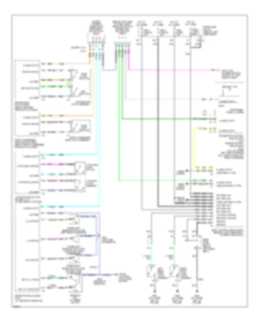
Anti-lock Brakes Wiring Diagram, with Traction Control for Chevrolet TrailBlazer 2005
 https://portal-diagnostov.com/license.html
Automotive Electricians Portal FZCO
Automotive Electricians Portal FZCO
https://portal-diagnostov.com/license.html
https://portal-diagnostov.com/license.html
Automotive Electricians Portal FZCO
Automotive Electricians Portal FZCOList of elements for Anti-lock Brakes Wiring Diagram, with Traction Control for Chevrolet TrailBlazer 2005:
- (4.2l)
- (5.3l)
- (on bottom left side of dash) data link connector (dlc)
- 2wd
- 4.2l
- 5.3l
- Abs fuse 33 60a
- Abs pump
- Anti-lock brake indicator
- Automatic a/c
- B10
- Body control module (bcm) (beneath left rear seat, on rear fuse block)
- Brake fluid level switch (on brake master cylinder fluid reservoir)
- Brake fluid lvl sig
- Brake fuse 51 10a
- Brake indicator
- C11
- Cruise control system
- Delivered torque sig
- Delivered torque signal
- Electronic brake control module (ebcm) (on inner left frame rail, beside transmission)
- G107 (on lower left side of engine)
- G201
- G304 (on outside of left frame rail, near electronic brake control module)
- Hot at all times
- Hot in run
- Hot in run or start
- Hvac 1 fuse 39 10a
- Ign e fuse 22 10a
- Ignition 3
- Instrument panel cluster
- Interior lights system
- Ipc/dic fuse 24 10a
- Left front wheel speed sensor (on left front spindle/hub assembly)
- Lf whl spd sens ref
- Lf whl spd sens sig
- Logic
- Low traction indicator
- Manual a/c
- Nca
- Pnk
- Powertrain control module (pcm) (4.2l) engine control module (ecm) (5.3l) (4.2l: on upper left side of engine) (5.3l: near lower left front of engine)
- Rear fuse block (below left rear seat)
- Red
- Requested torque sig
- Requested torque signal
- Rf whl spd sens ref
- Rf whl spd sens sig
- Right front wheel speed sensor (on right front spindle/hub assembly)
- S211
- S239
- Serial data
- Sp201 (at lower right front of lower console)
- Sp205 (behind left of dash, near headlamp switch connector)
- Stop lamp switch (on brake pedal assembly)
- Tan
- Tcc brake switch sig
- Trac active telltale
- Trac disable telltale
- Traction control switch
- Traction disable sw
- Traction disable switch
- Traction off indicator
- Underhood fuse block (on left side of engine compt)
- Vehicle speed signal
- Vss
Anti-lock Brakes Wiring Diagram, without Traction Control for Chevrolet TrailBlazer 2005
 https://portal-diagnostov.com/license.html
Automotive Electricians Portal FZCO
Automotive Electricians Portal FZCO
https://portal-diagnostov.com/license.html
https://portal-diagnostov.com/license.html
Automotive Electricians Portal FZCO
Automotive Electricians Portal FZCOList of elements for Anti-lock Brakes Wiring Diagram, without Traction Control for Chevrolet TrailBlazer 2005:
- (on bottom left side of dash) data link connector (dlc)
- 4.2l
- 5.3l
- A10
- Abs fuse 33 60a
- Abs pump
- Anti-lock brake indicator
- B10
- Body control module (bcm) (beneath left rear seat, on rear fuse block)
- Brake fluid level switch (on brake master cylinder fluid reservoir)
- Brake fuse 51 10a
- Brake indicator
- C11
- Cruise control system
- Electronic brake control module (ebcm) (on inner left frame rail, beside transmission)
- G107 (on lower left side of engine)
- G304 (on outside of left frame rail, near electronic brake control module)
- Hot at all times
- Hot in run
- Hot in run or start
- Ign 3
- Ign e fuse 22 10a
- Instrument panel cluster
- Ipc/dic fuse 24 10a
- Left front wheel speed sensor (on left front spindle/hub assembly)
- Lf sens low ref
- Lf sens sig
- Lvl sens sig
- Nca
- Pnk
- Powertrain control module (pcm) (4.2l) engine control module (ecm) (5.3l) (4.2l: on upper left side of engine) (5.3l: near lower left front of engine)
- Rear fuse block (below left rear seat)
- Red
- Rf sen low ref
- Rf sens sig
- Right front wheel speed sensor (on right front spindle/hub assembly)
- S239
- Serial data
- Sp205 (behind left of dash, near headlamp switch connector)
- Stop lamp switch (above brake pedal, on bracket)
- Tan
- Tcc brake sw
- Underhood fuse block (on left side of engine compt)
- Vehicle speed signal
- Vss
ANTI-THEFT
Forced Entry Wiring Diagram for Chevrolet TrailBlazer 2005
 https://portal-diagnostov.com/license.html
Automotive Electricians Portal FZCO
Automotive Electricians Portal FZCO
https://portal-diagnostov.com/license.html
https://portal-diagnostov.com/license.html
Automotive Electricians Portal FZCO
Automotive Electricians Portal FZCOList of elements for Forced Entry Wiring Diagram for Chevrolet TrailBlazer 2005:
- (behind left side of dash, near headlamp switch connector) splice pack sp205
- (in body harness,
- 4.2l
- 5.3l
- A10
- A11
- A12
- A14
- Ajar
- B c1
- B10
- B11
- B13
- B17
- Battery b(+)
- Body control module (bcm) (beneath left rear seat, on rear fuse block)
- C (xuv)
- C c1
- C1 a
- C1 d
- C4 b11
- Class 2 data
- Data link connector (dlc) (on bottom left side of dash)
- Door ajar sig
- Door ajar switch
- Down
- Driver door latch assembly
- Driver door module (ddm) (below driver's door switch panel)
- E12
- Endgate key cylinder switch
- Endgate module (egm) (xuv) (at center of endgate)
- Exterior lights system
- F10
- F14
- F8 c2
- Front passenger door latch assembly
- Front passenger door module (fpdm) (below front passenger door switch panel)
- G302 (on lower
- G303 (on lower
- Ground
- Head- lights system
- Headlamp relay ctrl
- Horn relay ctrl
- Horns system
- Hot at all times
- Instrument panel cluster
- K (except xuv)
- Key cyl down sig
- Key cyl up sig
- Key switch
- Key switch sig
- Left "b" pillar)
- Left rear door latch assembly
- Liftgate ajar sig
- Liftgate latch assembly
- Liftgate module (lgm) (except xuv) (in center of liftgate)
- Liftglass ajar sig
- Liftglass ajar switch
- Ll ajar sig
- Logic
- Low ref
- Lower left endgate actuator (lower left side of endgate)
- Lr door ajar sig
- Nca
- Parklamp relay ctrl
- Powertrain control module (pcm) (4.2l) engine control module (ecm) (5.3l) (4.2l: on upper left side of engine) (5.3l: near lower left front of engine)
- Rear fuse block (below left rear seat)
- Right "b" pillar)
- Right rear door latch assembly
- Rr door ajar sig
- S302
- S914 (left side of endgate)
- S915 (center of endgate)
- Security ind
- Tan
- Tbc 2 fuse 7 10a
- Tbc 3 fuse 4 10a
- Tbc 4 fuse 40 10a
- Tbc 5 fuse 32 10a
- Trunk, tailgate, fuel doors system
- Ul ajar sig
- Under right rear seat) splice pack sp306
- Upper left endgate actuator (left side of endgate)
- Upper right endgate actuator (at right side of endgate)
- Ur ajar sig
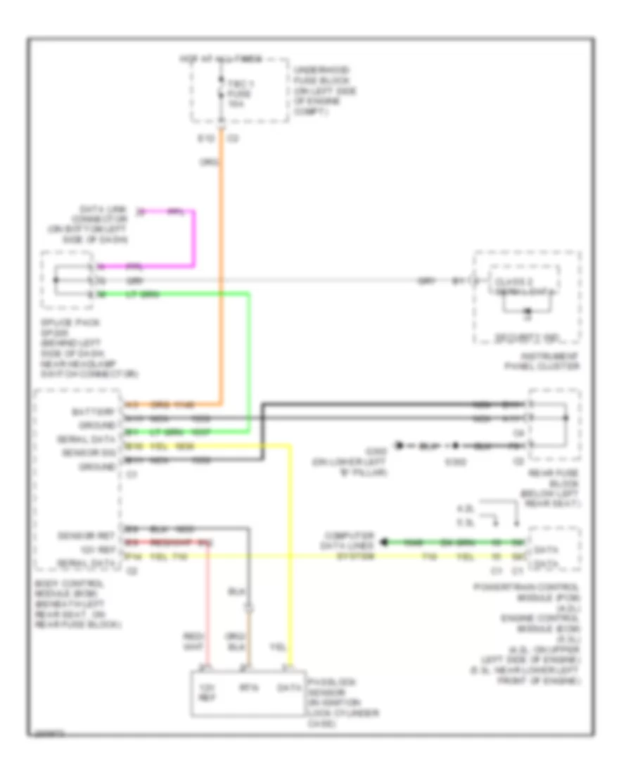
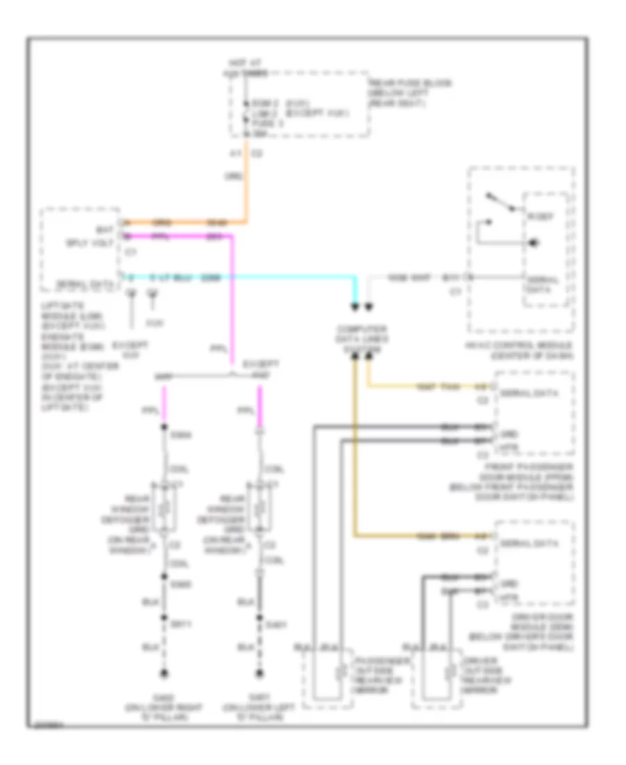
Passlock Wiring Diagram for Chevrolet TrailBlazer 2005
 https://portal-diagnostov.com/license.html
Automotive Electricians Portal FZCO
Automotive Electricians Portal FZCO
https://portal-diagnostov.com/license.html
https://portal-diagnostov.com/license.html
Automotive Electricians Portal FZCO
Automotive Electricians Portal FZCOList of elements for Passlock Wiring Diagram for Chevrolet TrailBlazer 2005:
- 12v ref
- 4.2l
- 5.3l
- A11
- B10
- B11
- Battery
- Body control module (bcm) (beneath left rear seat, on rear fuse block)
- Class 2 serial data
- Computer data lines system
- Data
- Data link connector (on bottom left side of dash)
- E12
- F14
- G302 (on lower left "b" pillar)
- Ground
- Hot at all times
- Instrument panel cluster
- Nca
- Passlock sensor (in ignition lock cylinder case)
- Powertrain control module (pcm) (4.2l) engine control module (ecm) (5.3l) (4.2l: on upper left side of engine) (5.3l: near lower left front of engine)
- Rear fuse block (below left rear seat)
- Rtn
- S302
- Security ind
- Sensor ret
- Sensor sig
- Serial data
- Splice pack sp205 (behind left side of dash, near headlamp switch connector)
- Tbc 1 fuse 10a
- Underhood fuse block (on left side of engine compt)
BODY CONTROL MODULES
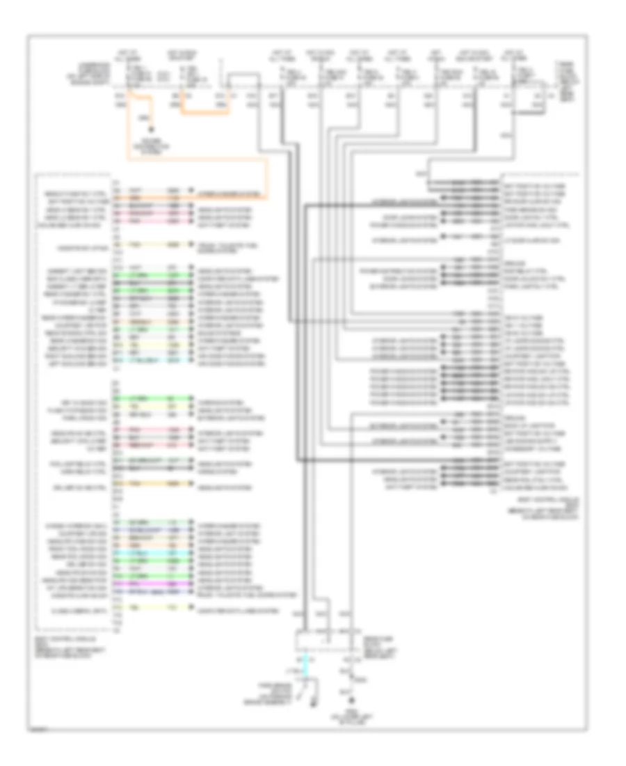
Body Control Modules Wiring Diagram for Chevrolet TrailBlazer 2005
 https://portal-diagnostov.com/license.html
Automotive Electricians Portal FZCO
Automotive Electricians Portal FZCO
https://portal-diagnostov.com/license.html
https://portal-diagnostov.com/license.html
Automotive Electricians Portal FZCO
Automotive Electricians Portal FZCOList of elements for Body Control Modules Wiring Diagram for Chevrolet TrailBlazer 2005:
- (4.2l) (5.3l)
- (gmc)
- 12v ref
- 5v ref
- A10
- A11
- A12
- A13
- A14
- A15
- A16
- A17
- A18
- A19
- A20
- A3 bat positive voltage a4
- Accessory voltage
- Air conditioning system
- Ambient light sen sig
- Ambient lt sen lo ref
- Anti-theft system
- B1 c1
- B10
- B11
- B12
- B13
- B14
- B15
- B16
- B17
- B18
- B19
- B20
- Back up lamp pwr
- Bat positive voltage
- Bcm class 2 ser data
- Body control module (bcm) (beneath left rear seat, on rear fuse block)
- C4 b11
- Class 2 serial data
- Computer data lines system
- Courtesy lamp pwr
- Courtesy lps pwr
- Courtesy lps sig
- D12
- Door lock rly ctrl
- Door locks system
- Door unlock rly ctrl
- Drl def on ind ctrl
- Drl def sw sig
- E10
- E11
- E12
- E13
- E14
- E15
- E16
- E5 c2
- Exterior lights system
- F10
- F11
- F12
- F13
- F14
- F15
- F16
- F8 c2
- Flash-to-pass sw sig
- Fog lamp relay ctrl
- Front fog lps sw sig
- G302 (on lower left "b" pillar)
- Ground
- Head hi beam rly ctrl
- Head lo beam rly ctrl
- Headlights system
- Headlp wash rly ctrl
- Headlps high beam pwr
- Headlps on ind ctrl
- Headlps sw on sig
- Headlps wash sw sig
- Horn relay ctrl
- Horns system
- Hot at all times
- Hot in acc or run
- Hot in acc, run or start
- Hot in run
- Hot in run or start
- I/p dimmer sw lo ref
- I/p lamps dimming ctrl
- Ign 1 voltage
- Ign b voltage
- Ign d voltage
- Inclne sen alrm on sig
- Int lps defeat sw sig
- Interior light system
- Interior lights system
- Key in ign sw sig
- Left sunload sen sig
- Lf door ajar sw sig
- Lr pwr wnd lkout ctrl
- Lr pwr wnd sw dn ctrl
- Lr pwr wnd sw up ctrl
- Midgate ajar ind sw
- Midgate sw up sig
- Nca
- Park brake sw sig
- Park brake switch (on parking brake assembly)
- Park lamp rly ctrl
- Park lps sw sig
- Pnk
- Power distribution system
- Power windows system
- Rap relay ctrl
- Rear fog lp rly ctrl
- Rear fog lps sw sig
- Rear fuse block (below left rear seat)
- Rear washer rly ctrl
- Rear washer sw sig
- Rear wiper/washer sw
- Remote radio ctrl sig
- Right sunload sen sig
- Rr door ajar sw sig
- Rr pwr wnd lkout ctrl
- Rr pwr wnd sw dn ctrl
- Rr pwr wnd sw up ctrl
- S302
- Security sys lo ref
- Security sys sen sig
- Sound systems
- Tan
- Tbc 1 fuse 31 fuse 58 10a
- Tbc 2 fuse 7 10a
- Tbc 3 fuse 4 10a
- Tbc 4 fuse 40 10a
- Tbc 5 fuse 32 10a
- Tbc acc fuse 31 3a
- Tbc ig fuse 50 3a
- Tbc ign 1 fuse 16 10a
- Tbc run fuse 52 3a
- Trunk, tailgate, fuel doors system
- Underhood fuse block (on left side of engine compt)
- Warning system
- Windsh wiper sw sig 2
- Wiper/washer system
COMPUTER DATA LINES
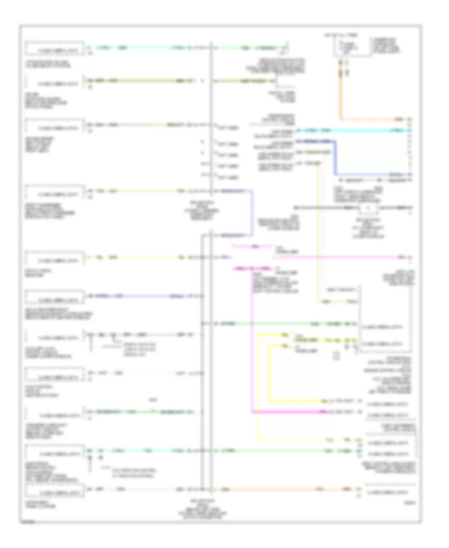
Computer Data Lines Wiring Diagram for Chevrolet TrailBlazer 2005
 https://portal-diagnostov.com/license.html
Automotive Electricians Portal FZCO
Automotive Electricians Portal FZCO
https://portal-diagnostov.com/license.html
https://portal-diagnostov.com/license.html
Automotive Electricians Portal FZCO
Automotive Electricians Portal FZCOList of elements for Computer Data Lines Wiring Diagram for Chevrolet TrailBlazer 2005:
- (5.3l: near lower left front of engine)
- 4.2l
- 4wd
- 5.3l
- A11
- Auxiliary hvac control module (under lower console)
- B11
- Body control module (bcm) (beneath left rear seat, on rear fuse block)
- Cigar fuse 13 20a
- Class 2 serial data
- D (not used)
- Data link connector (dlc) (on bottom left side of dash)
- Digital radio receiver
- Digital video disc (dvd) player
- Driver door module (ddm) (below driver's door switch panel)
- Driver memory seat module (below left front seat)
- E (not used)
- Electronic brake control module (ebcm) (on inner left frame rail, beside transmission)
- F14
- Front passenger door module (fpdm) (below front passenger door switch panel)
- G (not used)
- G102 (left side of underhood compt, near rear of underhood fuse block)
- G201 (ground splice pack, near right front of lower console)
- H (not used)
- High speed gmlan serial data +
- High speed gmlan serial data -
- High speed gmlan serial data bus +
- High speed gmlan serial data bus -
- Hot at all times
- Hvac control module (center of dash)
- Inflatable restraint sensing & diagnostic module (sdm) (below rear of center console)
- Instrument panel cluster
- L (not used)
- Liftgate module (lgm) (in center of liftgate)
- Lwb w/ auto a/c
- Manual a/c
- Powertrain control module (pcm) (4.2l) engine control module (5.3l) (4.2l: on upper left side of engine)
- Radio
- S202
- S232 (i/p harness, 10 cm from steering column breakout, toward shift control module)
- Splice pack sp201 (at lower right front of lower console)
- Splice pack sp205 (behind left side of dash, near headlamp switch connector)
- Splice pack sp306 (in body harness, under right rear seat)
- Swb w/ auto a/c
- Tan
- Theft deterrent control module
- Transfer case shift control module (behind lower left side of dash)
- Transmission control module (tcm)
- Underhood fuse block (on left side of eng compt)
- Vehicle communication interface module (vcim) (swb; under right rear seat) (lwb; right rear floor pan)
- W/ immobilizer
- W/ traction control
- W/o immobilizer
- W/o traction control
COOLING FAN
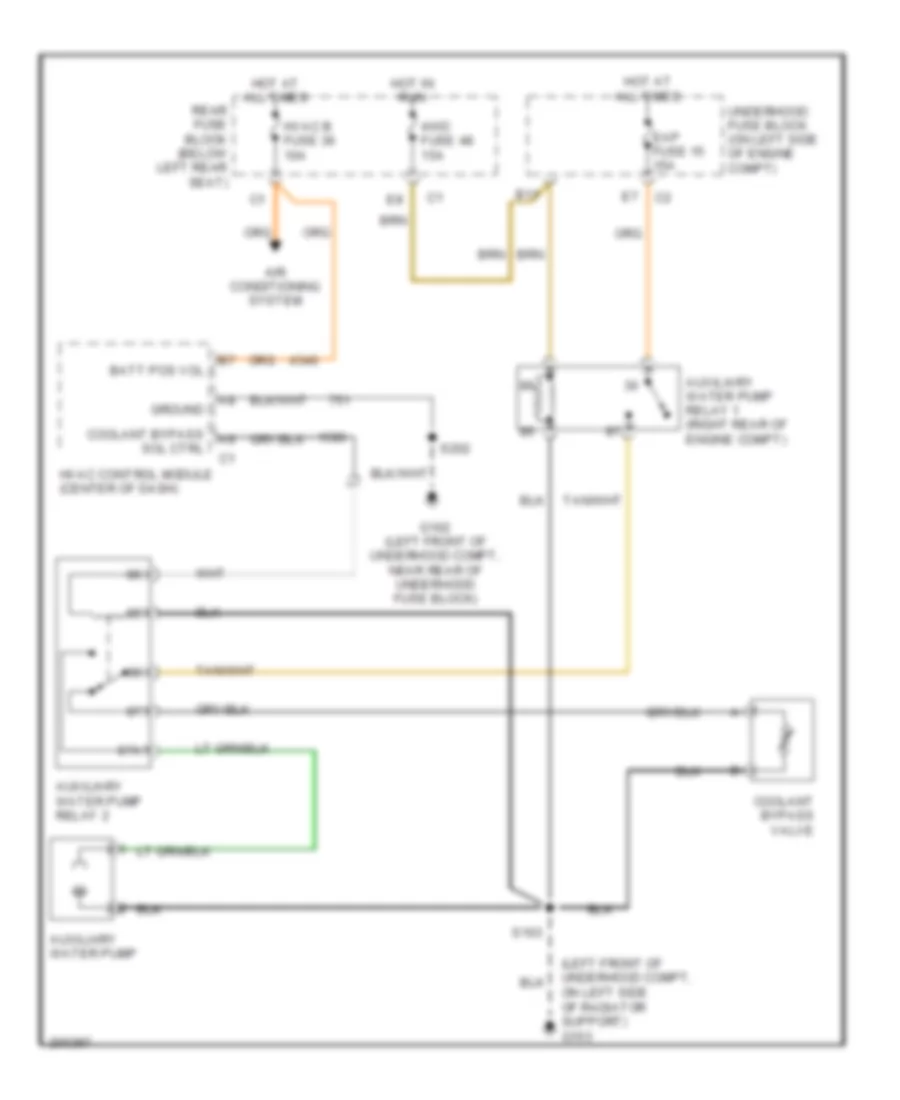
Auxiliary Cooling Fan Wiring Diagram for Chevrolet TrailBlazer 2005
 https://portal-diagnostov.com/license.html
Automotive Electricians Portal FZCO
Automotive Electricians Portal FZCO
https://portal-diagnostov.com/license.html
https://portal-diagnostov.com/license.html
Automotive Electricians Portal FZCO
Automotive Electricians Portal FZCOList of elements for Auxiliary Cooling Fan Wiring Diagram for Chevrolet TrailBlazer 2005:
- (left front of underhood compt, on left side of radiator support) g103
- 4wd fuse 48 15a
- 87a
- Air conditioning system
- Auxiliary water pump
- Auxiliary water pump relay 1 (right rear of engine compt)
- Auxiliary water pump relay 2
- B11
- Batt pos vol
- Coolant bypass sol ctrl
- Coolant bypass valve
- Eap fuse 15 15a
- G102 (left front of underhood compt, near rear of underhood fuse block)
- Ground
- Hot at all times
- Hot in run
- Hvac b fuse 36 10a
- Hvac control module (center of dash)
- Rear fuse block (below left rear seat)
- S103
- S202
- Underhood fuse block (on left side of engine compt)
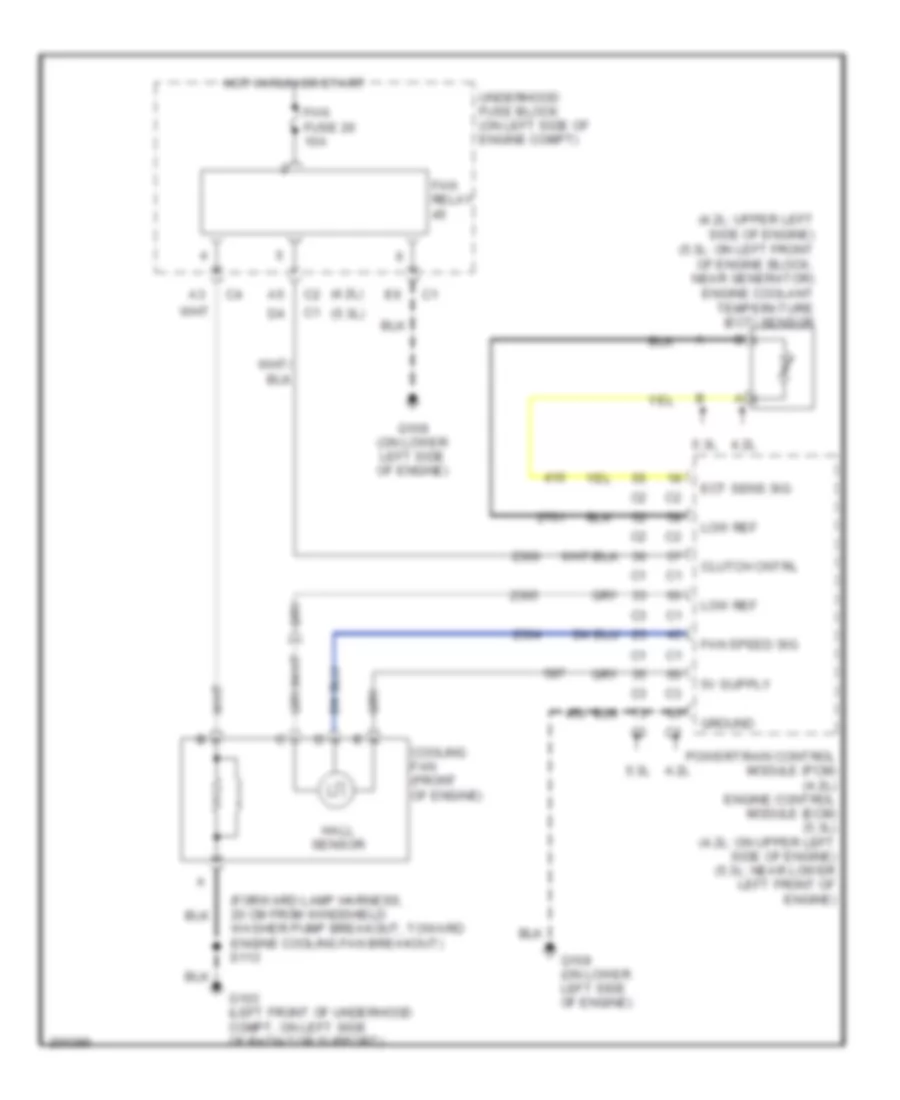
Cooling Fan Wiring Diagram for Chevrolet TrailBlazer 2005
 https://portal-diagnostov.com/license.html
Automotive Electricians Portal FZCO
Automotive Electricians Portal FZCO
https://portal-diagnostov.com/license.html
https://portal-diagnostov.com/license.html
Automotive Electricians Portal FZCO
Automotive Electricians Portal FZCOList of elements for Cooling Fan Wiring Diagram for Chevrolet TrailBlazer 2005:
- (4.2l)
- (4.2l: upper left side of engine) (5.3l: on left front of engine block, near generator) engine coolant temperature (ect) sensor
- (5.3l)
- (forward lamp harness, 20 cm from windshield washer pump breakout, toward engine cooling fan breakout) s113
- 4.2l
- 5.3l
- Clutch cntrl
- Cooling fan (front of engine)
- Ect sens sig
- Fan fuse 20 10a
- Fan relay
- Fan speed sig
- G103 (left front of underhood compt, on left side of radiator support)
- G108 (on lower left side of engine)
- Ground
- Hall sensor
- Hot in run or start
- Low ref
- Powertrain control module (pcm) (4.2l) engine control module (ecm) (5.3l) (4.2l: on upper left side of engine) (5.3l: near lower left front of engine)
- Underhood fuse block (on left side of engine compt)
CRUISE CONTROL
4.2L VIN S
4.2L VIN S, Cruise Control Wiring Diagram for Chevrolet TrailBlazer 2005
 https://portal-diagnostov.com/license.html
Automotive Electricians Portal FZCO
Automotive Electricians Portal FZCO
https://portal-diagnostov.com/license.html
https://portal-diagnostov.com/license.html
Automotive Electricians Portal FZCO
Automotive Electricians Portal FZCOList of elements for 4.2L VIN S, Cruise Control Wiring Diagram for Chevrolet TrailBlazer 2005:
- 5 volt ref
- Accelerator pedal position (app) sensor (above accelerator pedal, on bracket)
- App sensor 1
- App sensor 2
- B10
- B4 c1
- C9 c2
- Close
- Cruise ind
- Cruise release
- E3 c3
- Electronic brake control module (ebcm) (on inner left frame rail, beside transmission)
- Exterior lights system
- Hot at all times
- Hot in run
- Hot in run or start
- Hvac i fuse 39 10a
- Ign
- Ign e fuse 22 10a
- Instrument panel cluster (ipc)
- Ipc class 2 serial data
- Logic
- Low ref
- On sw
- On/off switch
- Open
- Pnk
- Power distribution system
- Powertrain control module (on upper left side of engine)
- Rear fuse block (below left rear seat)
- Res/accel sw
- Res/accel switch
- S239
- Serial data
- Set/coast sw
- Set/coast switch
- Sp205 (behind left of dash, near headlamp switch connector)
- St/lp fuse 12 25a
- Stop lamp input
- Stop lamp switch (on brake pedal assembly)
- Tac motor ctrl 1
- Tac motor ctrl 2
- Tan
- Throttle body
- Tp sensor 1
- Tp sensor 2
- Turn signal/ multifunction switch
- Underhood fuse block (on left side of engine compartment)
- Veh stop fuse 34 15a
- Vehicle speed sensor (vss) (on left rear of transfer case)
- Vehicle speed sig
- Vss hi
- Vss lo
- W/ traction control
- W/o traction control
5.3L VIN M
5.3L VIN M, Cruise Control Wiring Diagram for Chevrolet TrailBlazer 2005
 https://portal-diagnostov.com/license.html
Automotive Electricians Portal FZCO
Automotive Electricians Portal FZCO
https://portal-diagnostov.com/license.html
https://portal-diagnostov.com/license.html
Automotive Electricians Portal FZCO
Automotive Electricians Portal FZCOList of elements for 5.3L VIN M, Cruise Control Wiring Diagram for Chevrolet TrailBlazer 2005:
- (behind left of dash, near headlamp switch connector) sp205
- 5 volt ref
- Accelerator pedal position (app) sensor (above accelerator pedal, on bracket)
- App sensor 1
- App sensor 2
- B10
- Batt
- C9 c2
- Close
- Cruise ind
- Cruise release
- E3 c3
- Electronic brake control module (ebcm) (on inner left frame rail, beside transmission)
- Engine control module (ecm) (near lower left front of engine)
- Exterior lights system
- G108 (on lower left side of engine)
- Gnd
- Hot at all times
- Hot in run
- Hot in run or start
- Hvac i fuse 39 10a
- Ign
- Ign e fuse 22 10a
- Instrument panel cluster (ipc)
- Ipc class 2 serial
- Logic
- Low ref
- On sw
- On/off switch
- Open
- Pnk
- Power distribution system
- Rear fuse block (below left rear seat)
- Res/accel sw
- Res/accel switch
- S101
- S105
- S239
- Serial data
- Serial data bus +
- Serial data bus -
- Set/coast sw
- Set/coast switch
- St/lp fuse 12 25a
- Stop lamp in stop lamp in stop lamp in
- Stop lamp input
- Stop lamp switch (on brake pedal assembly)
- Tac motor ctrl 1
- Tac motor ctrl 2
- Tan
- Throttle body
- Tp sensor 1
- Tp sensor 2
- Transmission control module (tcm)
- Turn signal/ multifunction switch
- Underhood fuse block (on left side of engine compartment)
- Veh stop fuse 34 15a
- Vehicle speed sensor (vss) (on left rear of transfer case)
- Vehicle speed sig
- Vss hi
- Vss lo
- W/ traction control
- W/o traction control
DEFOGGERS
Defoggers Wiring Diagram for Chevrolet TrailBlazer 2005
 https://portal-diagnostov.com/license.html
Automotive Electricians Portal FZCO
Automotive Electricians Portal FZCO
https://portal-diagnostov.com/license.html
https://portal-diagnostov.com/license.html
Automotive Electricians Portal FZCO
Automotive Electricians Portal FZCOList of elements for Defoggers Wiring Diagram for Chevrolet TrailBlazer 2005:
- (except xuv: in center of liftgate)
- (xuv) (except xuv)
- A1 c2
- B11
- Bat
- Coil
- Computer data lines system
- Driver door module (ddm) (below driver's door switch panel)
- Driver outside rearview mirror
- Egm 2 lgm 2 fuse 3 30a
- Except xuv
- Front passenger door module (fpdm) (below front passenger door switch panel)
- G401 (on lower left "d" pillar)
- G402 (on lower right "d" pillar)
- Grd
- Hot at all times
- Htr
- Hvac control module (center of dash)
- Liftgate module (lgm) (except xuv) endgate module (egm) (xuv) (xuv: at center of endgate)
- Passenger outside rearview mirror
- R def
- Rear fuse block (below left rear seat)
- Rear window defogger grid (on rear a window)
- S401
- S904
- S905
- S911
- Serial data
- Sply volt
- Tan
- Xuv
ELECTRONIC SUSPENSION
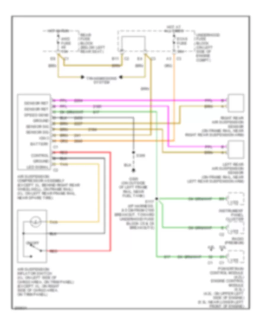
Electronic Suspension Wiring Diagram for Chevrolet TrailBlazer 2005
 https://portal-diagnostov.com/license.html
Automotive Electricians Portal FZCO
Automotive Electricians Portal FZCO
https://portal-diagnostov.com/license.html
https://portal-diagnostov.com/license.html
Automotive Electricians Portal FZCO
Automotive Electricians Portal FZCOList of elements for Electronic Suspension Wiring Diagram for Chevrolet TrailBlazer 2005:
- 4.2l
- 4wd fuse 15a
- 5.3l
- Air suspension compressor assembly (except xl: behind right rear wheelwell, on frame rail) (xl: on left rear frame rail, near spare tire)
- Air suspension inflator switch (xl: on left side of cargo area, on trim panel) (except xl: on right side of cargo area, on trim panel)
- B11
- Battery
- Control
- Ecas fuse 30a
- G305 (on outside of left frame rail, near fuel tank)
- Ground
- Hot at all times
- Hot in run
- Ign 3
- Instrument panel cluster
- Led signal
- Left rear air suspension sensor (on frame rail, near left rear suspension arm)
- On/off
- Powertrain control module (4.2l) engine control module (5.3l) (4.2l: on upper left side of engine) (5.3l: near lower left front of engine)
- Radio (premium)
- Rear fuse block (below left rear seat)
- Red
- Right rear air suspension sensor (on frame rail, near right rear suspension arm)
- S117 (i/p harness, 8.5 cm from c100 breakout, toward underhood fuse block c5 & c6 breakouts)
- S306
- Sensor ret
- Sensor sig
- Speed sens
- Tan
- Transmissions system
- Underhood fuse block (on left side of engine compt)
- Vss
ENGINE PERFORMANCE
4.2L VIN S
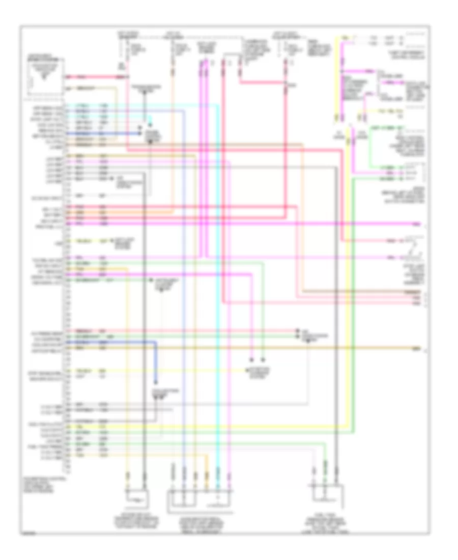
4.2L VIN S, Engine Performance Wiring Diagram (1 of 5) for Chevrolet TrailBlazer 2005
 https://portal-diagnostov.com/license.html
Automotive Electricians Portal FZCO
Automotive Electricians Portal FZCO
https://portal-diagnostov.com/license.html
https://portal-diagnostov.com/license.html
Automotive Electricians Portal FZCO
Automotive Electricians Portal FZCOList of elements for 4.2L VIN S, Engine Performance Wiring Diagram (1 of 5) for Chevrolet TrailBlazer 2005:
- 4wd low sig
- 5 volt ref
- A/c compr rel
- A/c press sens
- Accelerator pedal position (app) sensor (above accelerator pedal, on bracket)
- Air conditioning system
- Air pump relay
- Anti-lock brakes system
- App sens 1 sig
- App sens 2 sig
- B10
- Battery
- Body control module (bcm) (under left rear seat, on rear fuse block)
- Cc on sw input
- Cls 2 data
- Cool fan clutch
- Cooling fan sp
- Cooling fans system
- Crank voltage
- Cruise control system
- Data link connector (bottom left side of dash)
- Eng spd sig out
- F14
- Fuel tank press
- Fuel tank pressure sensor (swb: top left rear of fuel tank) (lwb: top of fuel tank)
- Hot at all times
- Hot in accy, run or start
- Hot in run or start
- Iat sens sig
- Ign 0 fuse 47 10a
- Ign 0 input
- Ign 1 volt
- Ign e fuse 22 10a
- Instrument cluster system
- Instrument panel cluster
- Intake air (iat) temperature sensor (in air intake duct, on top right of engine)
- Lo ref
- Low ref
- Malfunction indicator lamp
- Mil ctrl
- Pcm b fuse 10 20a
- Pnk
- Pnp sw input
- Powertrain control module (pcm) (on upper left side of engine)
- Prim fuel lvl
- Rear fuse block (below left rear seat)
- Res/acc sw
- S232 (i/p harness, 10 cm from steering column breakout)
- S239
- S320
- Set/cruise sw
- Sp205 (behind left of dash, near headlamp switch connector)
- Starting/ charging system
- Stop lamp switch (on brake pedal assembly)
- Stop lamp volt
- Strt enable rel
- Tan
- Tcc rel sw sig
- Theft deterrent control module
- Transmissions system
- Underhood fuse block (on left side of engine compt) c2
- Vss
- Vss signal out
- W/ immob
- W/ immobilizer
- W/o immob
- W/o immobilizer
4.2L VIN S, Engine Performance Wiring Diagram (2 of 5) for Chevrolet TrailBlazer 2005
 https://portal-diagnostov.com/license.html
Automotive Electricians Portal FZCO
Automotive Electricians Portal FZCO
https://portal-diagnostov.com/license.html
https://portal-diagnostov.com/license.html
Automotive Electricians Portal FZCO
Automotive Electricians Portal FZCOList of elements for 4.2L VIN S, Engine Performance Wiring Diagram (2 of 5) for Chevrolet TrailBlazer 2005:
- A11
- Air fuse 56 60a
- Air sol fuse 54 15a
- Air sol relay
- D11
- E11
- Eng i fuse 26 10a
- Engine oil pressure switch (right side of engine block)
- Evaporative emission (evap) canister purge solenoid (lower left side of engine)
- Evaporative emission (evap) canister vent solenoid (lwb: rear of fuel tank) (swb: top of fuel tank)
- F/pmp relay
- Fuel pump/ & sender assembly (swb: inside fuel tank) (lwb: top of fuel tank)
- G107 (lower left side of engine)
- G107 (on lower left side of engine)
- G305 (outside of left frame rail, near fuel tank)
- Hot at all times
- Hot in run or start
- Nca
- Pcm b fuse 10 20a
- Pnk
- Power distribution system
- Red
- S306
- Secondary air injection pump (left front of chassis)
- Secondary air injection pump relay (left front of chassis)
- Secondary air injection solenoid (upper right side of engine)
- Underhood fuse block (on left side of engine compt)
- Underhood fuse block (on left side of engine compt) c1
- Vehicle speed sensor (vss) (left rear of transfer case)
4.2L VIN S, Engine Performance Wiring Diagram (3 of 5) for Chevrolet TrailBlazer 2005
 https://portal-diagnostov.com/license.html
Automotive Electricians Portal FZCO
Automotive Electricians Portal FZCO
https://portal-diagnostov.com/license.html
https://portal-diagnostov.com/license.html
Automotive Electricians Portal FZCO
Automotive Electricians Portal FZCOList of elements for 4.2L VIN S, Engine Performance Wiring Diagram (3 of 5) for Chevrolet TrailBlazer 2005:
- 1310
- (left rear of engine block, below starter) crankshaft (ckp) position sensor
- (top of engine) injectors
- 1-2 shift sol ctrl
- 2-3 shift sol ctrl
- 3-2 shift sol
- 5v ref
- Anti-lock brakes system
- Cam pos sol hi
- Camshaft actuator solenoid assembly (right front of cylinder head)
- Ckp sens sig
- Deliv torque sig
- Ect sens sig
- Engine coolant temperature (ect) sensor (upper left side of engine)
- Evap can prg ctl
- Evap can vent
- Fuel inj 1
- Fuel inj 2
- Fuel inj 3
- Fuel inj 4
- Fuel inj 5
- Fuel inj 6
- G108 (on lower left side of engine)
- Gfd cyc sig
- Ground powertrain control module (pcm) (on upper left side of engine)
- H02s hi sig sens 1
- H02s hi sig sens 2
- H02s lo sig sens 2
- Heated oxygen sensor 1 (on exhaust manifold, on right side of engine)
- Heated oxygen sensor 2 (downstream of catalytic converter)
- Ho2s htr lo s1
- Ho2s htr lo s2
- Ho2s lo sig s1
- Hot in run or start
- Ic 1 ctrl
- Ic 2 ctrl
- Ic 3 ctrl
- Ic 4 ctrl
- Ic 5 ctrl
- Ic 6 ctrl
- Low ref
- Manifold absolute pressure sensor (on upper left side of engine)
- Map sens sig
- Nca
- O2 fuse 29
- Oil pres sw sig
- Pc sol high ctrl
- Pc sol low ctrl
- Pcm i fuse 28 15a
- Pnk
- Powertrain control module (pcm) (on upper left side of engine)
- Prim fuel pmp rel
- Req torque sig
- S111
- Starting/ charging system
- Tan
- Tcc pwm sol
- Tcc sol vlv ctrl
- Trns rg sw sig a
- Underhood fuse block (on left side of engine compt)
- Vss high sig
- Vss low signal
4.2L VIN S, Engine Performance Wiring Diagram (4 of 5) for Chevrolet TrailBlazer 2005
 https://portal-diagnostov.com/license.html
Automotive Electricians Portal FZCO
Automotive Electricians Portal FZCO
https://portal-diagnostov.com/license.html
https://portal-diagnostov.com/license.html
Automotive Electricians Portal FZCO
Automotive Electricians Portal FZCOList of elements for 4.2L VIN S, Engine Performance Wiring Diagram (4 of 5) for Chevrolet TrailBlazer 2005:
- (on lower left side of transmission) park/neutral position switch
- 1-2 shift solenoid s133
- 2-3 shift solenoid
- 3-2 shift solenoid
- Automatic transmission
- Automatic transmission fluid
- C10
- Ctrl
- D10
- D2 sw
- D3 sw
- D4 sw
- E10
- F10
- G108 (on lower left side of engine)
- G109 (on lower left side of engine)
- Gnd
- Ign
- Ignition coils
- Lo sw
- Nca
- Pnk
- Pnk a
- Pressure control solenoid
- Red
- Rev sw
- Solenoid tcc pmw red
- Spark plug
- Tan
- Tcc solenoid red
- Temperature sensor
- Underhood fuse block (on left side of engine compt)
- Valve
4.2L VIN S, Engine Performance Wiring Diagram (5 of 5) for Chevrolet TrailBlazer 2005
 https://portal-diagnostov.com/license.html
Automotive Electricians Portal FZCO
Automotive Electricians Portal FZCO
https://portal-diagnostov.com/license.html
https://portal-diagnostov.com/license.html
Automotive Electricians Portal FZCO
Automotive Electricians Portal FZCOList of elements for 4.2L VIN S, Engine Performance Wiring Diagram (5 of 5) for Chevrolet TrailBlazer 2005:
- 839
- 12v ref
- 5v ref
- Air sol relay
- Camshaft position (cmp) sensor (right front of cylinder
- Cooling fans system
- Cpm sens sig
- Gen turn on sig
- Hot in run or start
- Ign 1 voltage
- Knock sensor 1 (front) (lower left front of engine block)
- Knock sensor 2 (rear) (lower left rear of engine block)
- Ks 1 sig
- Ks 2 sig
- Low oil press sw
- Low ref
- Pnk
- Powertrain control module (pcm) (upper left side of engine)
- Red
- Starting/charging system
- Tac fuse 23 10a
- Tac motor
- Tac mtr ctrl 1
- Tac mtr ctrl 2
- Tfp sw sig a
- Tfp sw sig b
- Tfp sw sig c
- Tft sens sig
- Throttle body
- Tp sens 1 sig
- Tp sens 2 sig
- Trs sig b
- Trs sig c
- Trs sig p
- Underhood fuse block (on left side of engine compt)
5.3L VIN M
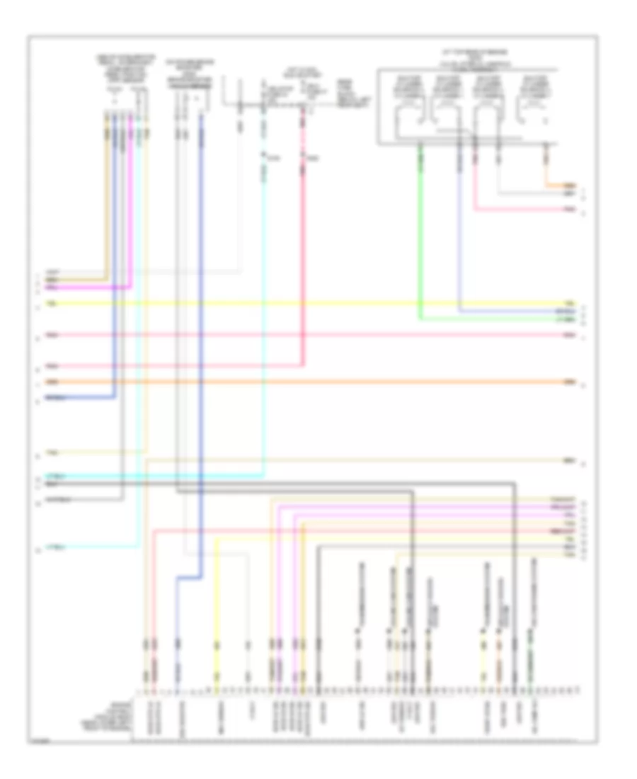
5.3L VIN M, Engine Performance Wiring Diagram (1 of 5) for Chevrolet TrailBlazer 2005
 https://portal-diagnostov.com/license.html
Automotive Electricians Portal FZCO
Automotive Electricians Portal FZCO
https://portal-diagnostov.com/license.html
https://portal-diagnostov.com/license.html
Automotive Electricians Portal FZCO
Automotive Electricians Portal FZCOList of elements for 5.3L VIN M, Engine Performance Wiring Diagram (1 of 5) for Chevrolet TrailBlazer 2005:
- 5 volt
- A/c ref pre sen
- A/c refrigerant pressure sensor (on high pressure line, near a/c compressor)
- A12
- Anti-lock brakes system
- App sens 1
- App sens 2
- Battery
- Computer data lines system
- Coo fan speed sig
- Cool fan clu ctrl
- Cooling fans system
- Crank fuse 17 10a
- Crank volt
- Cruise control system
- Cruise on sw sig
- Ecm i fuse 15a
- Eng speed sig
- Engine control module (ecm) (near lower left front of engine)
- Engine speed
- Evap can
- Evaporative emission (evap) canister vent solenoid (swb: at rear of fuel tank) (lwb: top of fuel tank)
- Exterior lights system
- Ftp sens
- Fuel lvl sens sig
- Fuel pump & sender assembly (swb: inside fuel tank) (lwb: top of fuel tank)
- Fuel pump rly
- Fuel tank pressure (ftp) sensor (swb: at top left rear of fuel tank) (lwb: top of fuel tank)
- Fuel/ pmp relay
- G107 (on lower left side of engine)
- G305 (on outside of left frame rail, near fuel tank)
- Hot at all times
- Hot in run or start
- Hot in start
- Ign 0 volt
- Ign 1 volt
- Ign e fuse 10a
- Instrument cluster system
- Instrument panel cluster
- Logic
- Low ref
- Malfunction indicator lamp
- Mil ctrl
- Pcm b fuse 10 20a
- Pnk
- Pnp sw
- Pwr diag
- Res/acc sw sig
- S239
- S306
- S359
- Serial data
- Set/coast sw sig
- St/lp fuse 12 25a
- Start relay
- Starting/charging system
- Stop lamp switch (on brake pedal assembly)
- Tan
- Tcc brake sw
- Tcm/ canister fuse 15 10a
- Underhood fuse block (on left side of engine compt)
- Vss
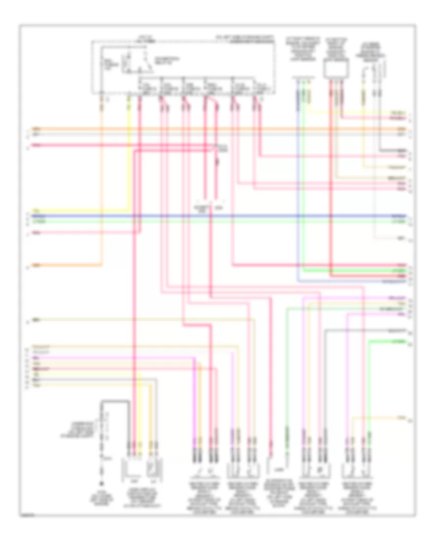
5.3L VIN M, Engine Performance Wiring Diagram (2 of 5) for Chevrolet TrailBlazer 2005
 https://portal-diagnostov.com/license.html
Automotive Electricians Portal FZCO
Automotive Electricians Portal FZCO
https://portal-diagnostov.com/license.html
https://portal-diagnostov.com/license.html
Automotive Electricians Portal FZCO
Automotive Electricians Portal FZCOList of elements for 5.3L VIN M, Engine Performance Wiring Diagram (2 of 5) for Chevrolet TrailBlazer 2005:
- (above accelerator pedal, on bracket) accelerator pedal position (app) sensor
- (at top rear of engine) (dod) valve lifter oil manifold (vlom) assembly
- (on power brake booster) (dod) brake booster vacuum sensor
- 4wd lo sig
- 5 volt
- A/c comp rly
- Air conditioning system
- Anti-lock brakes system
- Brk booster
- Cooling fans system
- Del torque
- Engine control module (ecm) (near lower left front of engine)
- Front hi sig
- Ho2s hi sig
- Ho2s htr lo
- Ho2s htr sig
- Ho2s lo sig
- Hot in acc, run or start
- Iat sensor
- Ign 0 fuse 47 10a
- Low ref
- Maf sensor
- Pnk
- Rear fuse block (below left rear seat)
- Req torq
- S105
- S320
- Shutoff cylinder solenoid 1, cylinder 1
- Shutoff cylinder solenoid 2, cylinder 4
- Shutoff cylinder solenoid 3, cylinder 6
- Shutoff cylinder solenoid 4, cylinder 7
- Tan
- Transmissions system
- Veh stop fuse 34 15a
5.3L VIN M, Engine Performance Wiring Diagram (3 of 5) for Chevrolet TrailBlazer 2005
 https://portal-diagnostov.com/license.html
Automotive Electricians Portal FZCO
Automotive Electricians Portal FZCO
https://portal-diagnostov.com/license.html
https://portal-diagnostov.com/license.html
Automotive Electricians Portal FZCO
Automotive Electricians Portal FZCOList of elements for 5.3L VIN M, Engine Performance Wiring Diagram (3 of 5) for Chevrolet TrailBlazer 2005:
- (at bottom front of engine) camshaft position (cmp) sensor
- (at rear of engine) engine oil pressure (eop) sensor
- (at right rear of engine, adjacent to starter) crankshaft position (ckp) sensor
- (on left side of engine block)
- (on left side of engine compt) underhood fuse block
- A11
- C1 c1
- C11
- Dod
- Ecm fuse 29 10a
- Eng i fuse 26 15a
- Evaporative emission (evap) canister purge solenoid
- Except dod
- F10
- F11 f11
- G108 (on lower left side of engine)
- Heated oxygen sensor (ho2s) bank 1 sensor 1 (in left bank exhaust pipe, ahead of catalytic converter)
- Heated oxygen sensor (ho2s) bank 1 sensor 2 (in left bank exhaust pipe, behind catalytic converter)
- Heated oxygen sensor (ho2s) bank 2 sensor 1 (in right bank of exhaust pipe, ahead of catalytic converter)
- Heated oxygen sensor (ho2s) bank 2 sensor 2 (in right bank of exhaust pipe, behind catalytic converter)
- Hot at all times
- Iat
- Inj a fuse 31 20a
- Inj b fuse 56 20a
- Maf
- Mass airflow (maf)/intake air temperature (iat) sensor (in air intake duct)
- Nca
- O2a fuse 55 10a
- O2b fuse 54 10a
- Pnk
- Pnk pnk
- Powertrain relay 60
- Red
- S101
- S112 (dod)
- Tac fuse 23 15a
- Tan
- Underhood fuse block (on left side of engine compt)
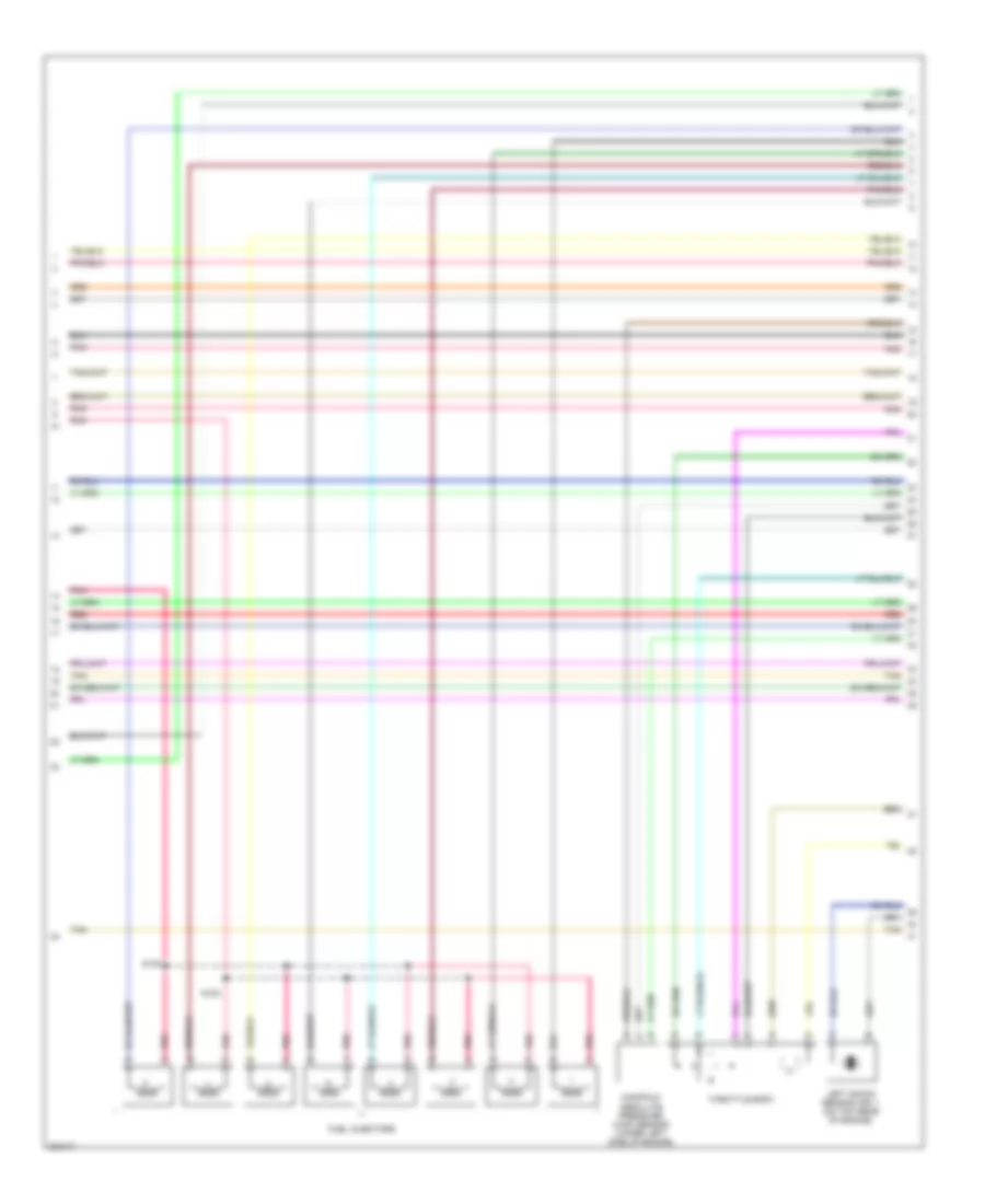
5.3L VIN M, Engine Performance Wiring Diagram (4 of 5) for Chevrolet TrailBlazer 2005
 https://portal-diagnostov.com/license.html
Automotive Electricians Portal FZCO
Automotive Electricians Portal FZCO
https://portal-diagnostov.com/license.html
https://portal-diagnostov.com/license.html
Automotive Electricians Portal FZCO
Automotive Electricians Portal FZCOList of elements for 5.3L VIN M, Engine Performance Wiring Diagram (4 of 5) for Chevrolet TrailBlazer 2005:
- Fuel injectors
- Left knock sensor (ks) 1 (on top rear of engine)
- Manifold absolute pressure (map) sensor (upper left side of engine)
- Pnk
- Red
- S100
- S102
- Tan
- Throttle body
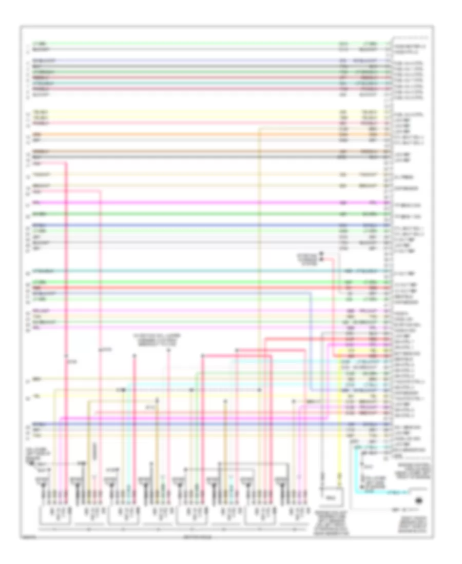
5.3L VIN M, Engine Performance Wiring Diagram (5 of 5) for Chevrolet TrailBlazer 2005
 https://portal-diagnostov.com/license.html
Automotive Electricians Portal FZCO
Automotive Electricians Portal FZCO
https://portal-diagnostov.com/license.html
https://portal-diagnostov.com/license.html
Automotive Electricians Portal FZCO
Automotive Electricians Portal FZCOList of elements for 5.3L VIN M, Engine Performance Wiring Diagram (5 of 5) for Chevrolet TrailBlazer 2005:
- (in ignition coil jumper
- (on lower left side of engine) g109
- 12 volt ref
- 5 volt ref
- Ckp sensor
- Cmp sensor
- Ctrl
- Cyl shut sol 1
- Cyl shut sol 2
- Cyl shut sol 3
- Cyl shut sol 4
- Ect sens sig
- Engine control module (ecm) (near lower left front of engine)
- Engine coolant temperature (ect) sensor (on left front of engine block, near generator)
- Evap can sol
- Fuel inj 1 ctrl
- Fuel inj 2 ctrl
- Fuel inj 3 ctrl
- Fuel inj 4 ctrl
- Fuel inj 5 ctrl
- Fuel inj 6 ctrl
- Fuel inj 7 ctrl
- Fuel inj 8 ctrl
- Gen field
- Gnd
- Harness, 5 cm from breakout to c108)
- Ho2s heater lo
- Ho2s hi
- Ho2s hi sig
- Ho2s htr lo
- Ho2s low
- Ho2s low sig
- Ign
- Ign ctrl 1
- Ign ctrl 2
- Ign ctrl 3
- Ign ctrl 4
- Ign ctrl 5
- Ign ctrl 6
- Ign ctrl 7
- Ign ctrl 8
- Ignition coils
- Ks 1 sens sig
- Ks 2 sensor sig
- Low ref
- Map sensor
- Nca
- Nca nca
- Oil press
- Pnk
- Red
- Ref lo
- Right knock sensor (ks) 2 (right side of engine block)
- S101
- S108
- S109
- S118
- S119
- S128
- S129
- Spark plug
- Starting/ charging system
- Tac mtr ctrl 1
- Tac mtr ctrl 2
- Tan
- Tp sens 1 sig
- Tp sens 2 sig
EXTERIOR LIGHTS
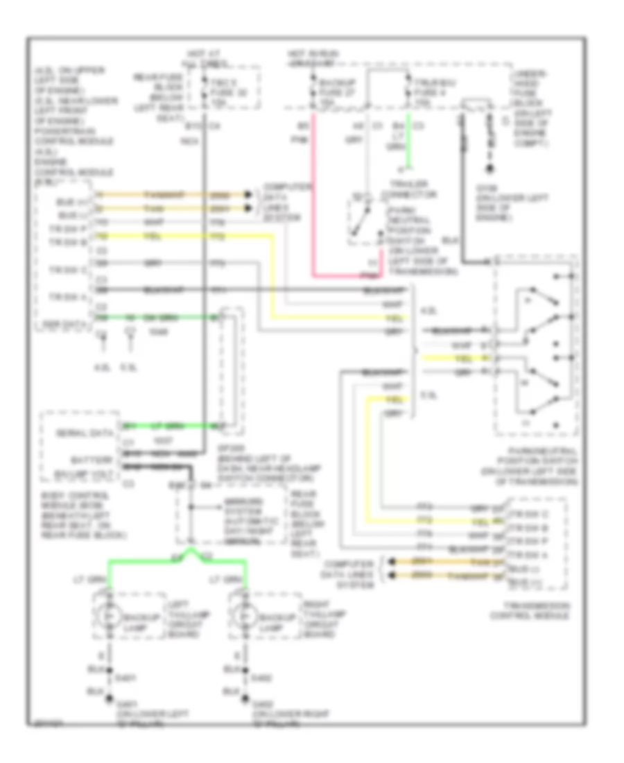
Back-up Lamps Wiring Diagram for Chevrolet TrailBlazer 2005
 https://portal-diagnostov.com/license.html
Automotive Electricians Portal FZCO
Automotive Electricians Portal FZCO
https://portal-diagnostov.com/license.html
https://portal-diagnostov.com/license.html
Automotive Electricians Portal FZCO
Automotive Electricians Portal FZCOList of elements for Back-up Lamps Wiring Diagram for Chevrolet TrailBlazer 2005:
- (4.2l: on upper left side of engine) (5.3l: near lower left front of engine) powertrain control module (4.2l) engine control module (5.3l)
- 4.2l
- 5.3l
- A9 c1
- B/u lmp volt
- B12
- B13
- B13 c4
- Backup fuse 27 15a
- Backup lamp
- Battery
- Body control module (bcm) (beneath left rear seat, on rear fuse block)
- Bus (+)
- Bus (-)
- C3 b4
- Computer data lines system
- G108 (on lower left side of engine)
- G401 (on lower left "d" pillar)
- G402 (on lower right "d" pillar)
- Hot at all times
- Hot in run or start
- Left taillamp circuit board
- Mirrors system (automatic day/ night mirror)
- Nca
- Park/ neutral position switch (on lower left side of transmission)
- Park/neutral position switch (on lower left side of transmission)
- Pnk
- Rear fuse block (below left rear seat)
- Right taillamp circuit board
- S401
- S402
- Ser data
- Serial data
- Sp205 (behind left of dash, near headlamp switch connector)
- Tan
- Tbc 5 fuse 32 10a
- Tr sw a
- Tr sw b
- Tr sw c
- Tr sw p
- Trailer connector
- Transmission control module
- Trlr b/u fuse 4 10a
- Under- hood fuse block (on left side of engine compt)
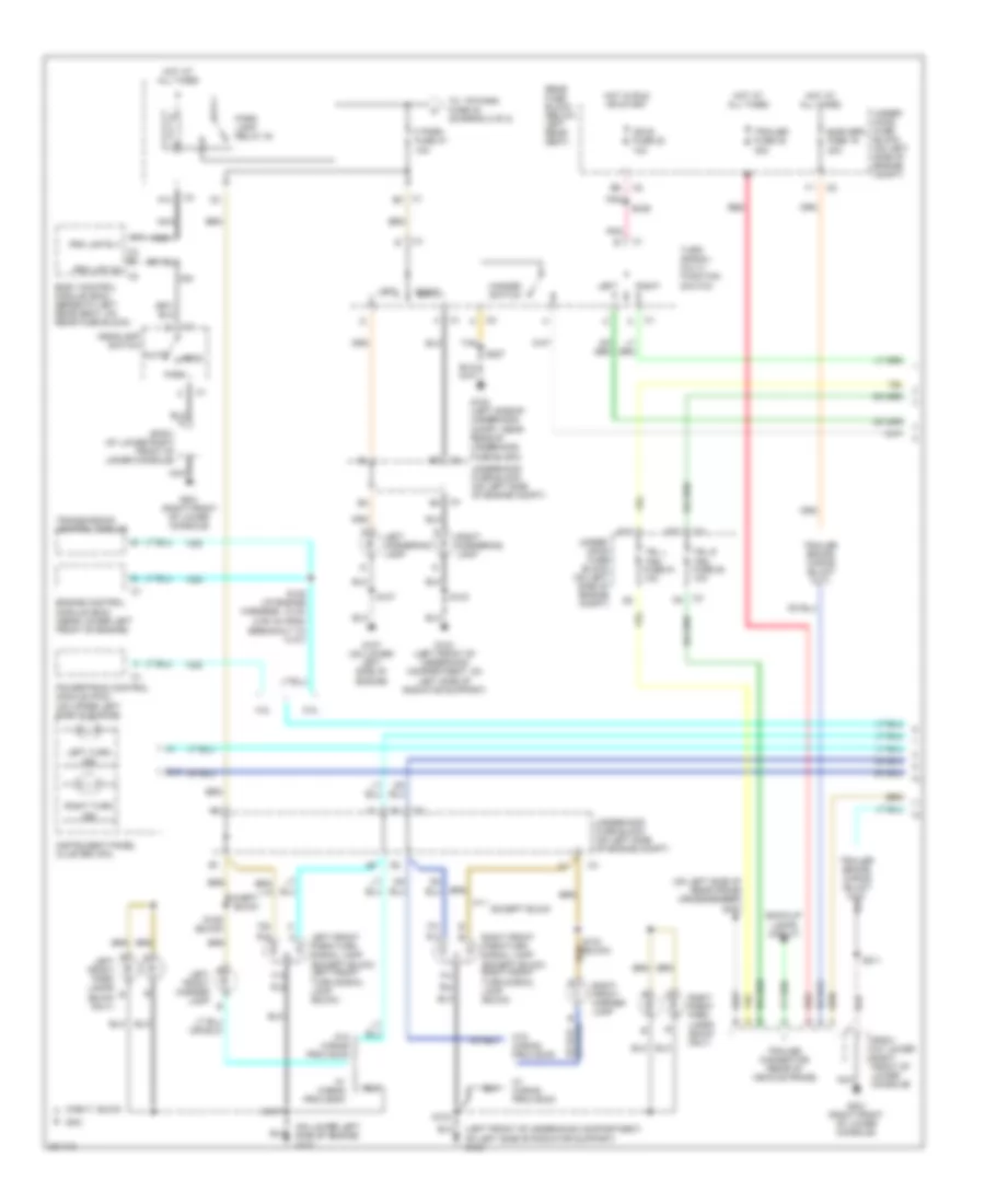
Exterior Lamps Wiring Diagram (1 of 2) for Chevrolet TrailBlazer 2005
 https://portal-diagnostov.com/license.html
Automotive Electricians Portal FZCO
Automotive Electricians Portal FZCO
https://portal-diagnostov.com/license.html
https://portal-diagnostov.com/license.html
Automotive Electricians Portal FZCO
Automotive Electricians Portal FZCOList of elements for Exterior Lamps Wiring Diagram (1 of 2) for Chevrolet TrailBlazer 2005:
- (3.94 in) from breakout to c107)
- (left front of underhood compartment, on left side of radiator support) g103
- (on left side of rear frame crossmember) g403
- (on lower left side of engine) g107
- 4.2l
- 5.3l
- A a
- A10
- A14
- Auto
- B g
- B gmc
- Back-up lamps circuit
- Body control module (bcm) (beneath left rear seat, on rear fuse block)
- C3 e5
- Chevy, buick a
- D10
- Elek brk fuse 19 30a
- Engine control module (ecm) (near lower left front of engine)
- Except buick
- F park fuse 37 10a
- G102 (left side of underhood compt, near rear of underhood fuse block)
- G103 (left front of underhood compartment, on left side of radiator support)
- G107 (on lower left side of engine)
- G201 (right front of lower console)
- Hazard switch
- Head
- Headlamp switch
- Hot at all times
- Hot in run or start
- Ign e fuse 22 10a
- Instrument panel cluster (ipc)
- Left
- Left cornering lamp
- Left front marker lamp
- Left front park lamps (buick only)
- Left front park/turn signal lamp (except buick) left front turn signal lamp (buick)
- Left turn ind
- Nca
- Park
- Park lamp relay 30
- Pnk
- Powertrain control module (pcm) (on upper left side of engine)
- Prk lmp on
- Prk lmp rly
- Rear fuse block (below left rear seat)
- Red
- Right
- Right cornering lamp
- Right front marker lamp
- Right front park lamps (buick only)
- Right front park/turn signal lamp (except buick) right front turn signal lamp (buick)
- Right turn ind
- S103
- S104 (buick)
- S105 (i/p engine harness, 10 cm
- S106 (buick)
- S107
- S211
- S227
- S239
- Sp201 (at lower right front of lower console)
- Tan
- To tr park fuse 42 (diagram 2 0f 2)
- Trailer connector (rear of vehicle frame)
- Trailer fuse 32 30a
- Transmission control module
- Trl l trn fuse 51 10a
- Trl r trn fuse 50 10a
- Turn signal/ multi- function switch
- Under- hood fuse block (on left side of engine compt)
- Underhood fuse block (on left side of engine compt)
- W/ wiring provision
- W/o wiring provision
Exterior Lamps Wiring Diagram (2 of 2) for Chevrolet TrailBlazer 2005
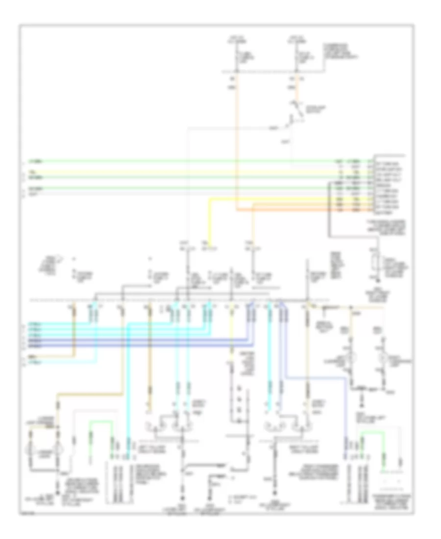 https://portal-diagnostov.com/license.html
Automotive Electricians Portal FZCO
Automotive Electricians Portal FZCO
https://portal-diagnostov.com/license.html
https://portal-diagnostov.com/license.html
Automotive Electricians Portal FZCO
Automotive Electricians Portal FZCOList of elements for Exterior Lamps Wiring Diagram (2 of 2) for Chevrolet TrailBlazer 2005:
- (chevy, buick)
- (gmc)
- (license lamp harness) s909
- Battery
- C3 e6
- Center high mount stop lamp (chmsl)
- D xuv
- Driver door module (ddm) (below driver's door switch panel)
- Driver outside rearview mirror (w/ mirror turn signal indicator)
- Except xuv c
- Flash fuse 52 25a
- From a f park fuse 37 (diagram 1 0f 2)
- Front passenger door module (fpdm) (below front passenger door switch panel)
- G201 (right front of lower console)
- G302 (on lower left "b" pillar)
- G401 (lower left "d" pillar)
- G401 (on lower left "d" pillar)
- G402 (on lower right "d" pillar)
- Ground
- Hazard sw
- Hot at all times
- Left clearance lamp
- Left taillamp circuit board
- License lamps
- Lr lamp volt
- Lr park fuse 14 10a
- Lt trn sig voltage
- Lt turn fuse 38 10a
- Lt turn sig
- Mirror lt turn sig
- Mirror rt turn sig
- Nca
- Passenger outside rearview mirror (w/ mirror turn signal indicator)
- Rear fuse block (below left rear seat)
- Right clearance lamp
- Right taillamp circuit board
- Rr lamp volt
- Rr park fuse 17 10a
- Rt trn sig voltage
- Rt turn fuse 43 10a
- Rt turn sig
- S312
- S322
- S360
- S401
- S402
- S902
- S912
- Sp201 (at lower right front of lower console)
- Special editions only
- St/lp fuse 12 25a
- Stoplamp sw
- Stoplamp switch
- Tan
- Tr park fuse 42 10a
- Turn signal/hazard flasher module (behind lower left side of dash)
- Underhood fuse block (on left side of engine compt)
- Veh chmsl fuse 16 10a
- Veh stop fuse 34 15a
GROUND DISTRIBUTION
Ground Distribution Wiring Diagram (1 of 6) for Chevrolet TrailBlazer 2005
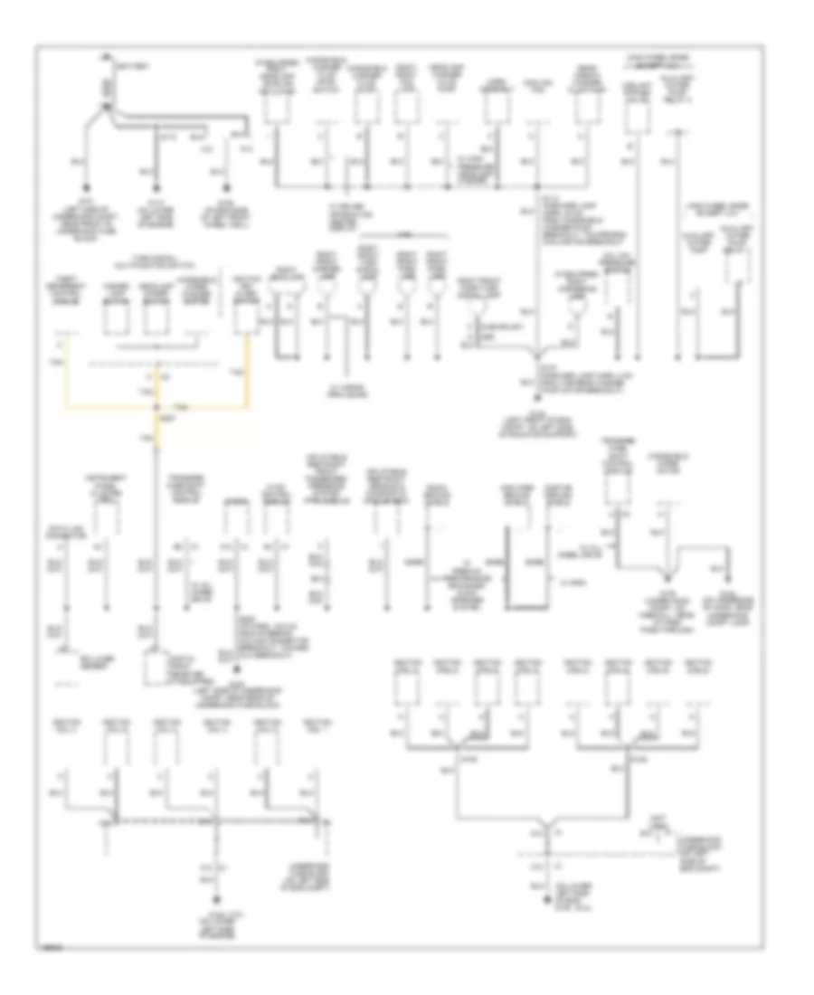 https://portal-diagnostov.com/license.html
Automotive Electricians Portal FZCO
Automotive Electricians Portal FZCO
https://portal-diagnostov.com/license.html
https://portal-diagnostov.com/license.html
Automotive Electricians Portal FZCO
Automotive Electricians Portal FZCOList of elements for Ground Distribution Wiring Diagram (1 of 6) for Chevrolet TrailBlazer 2005:
- (4.2l)
- (5.3l)
- (chevrolet)
- (if equipped) right cornering lamp
- (if equipped) right headlamp leveling actuator
- (not used)
- (on lower left side of eng) g109
- (z89)
- 4.2l
- 5.3l
- A/c low pressure switch
- A12
- Amplifier ground shield
- Auxiliary water pump
- Auxiliary water pump relay 1
- Auxiliary water pump relay 2
- Bare
- Battery
- C10
- Coolant bypass valve
- Cooling fan
- D10
- Data link connector
- Digital radio receiver (if equipped)
- E10
- F10
- G101 (left side of underhood compt, near front of underhood fuse block)
- G102 (left side of underhood compt, near rear of underhood fuse block)
- G103 (left front of eng compt, on left side of radiator support)
- G104 (on underside of hood, near underhood compt lamp)
- G105 (under hood compt, on firewall, near i/p harn pass-through)
- G106 (on eng side of left front wheel well)
- G109 (on lower left side of engine)
- G110 (on lower left side of engine)
- Hazard lamp switch
- Headlamp dimmer switch
- Headlamp washer fluid pump
- Horn assembly
- Hvac control module
- Ignition coil 1
- Ignition coil 2
- Ignition coil 3
- Ignition coil 4
- Ignition coil 5
- Ignition coil 6
- Ignition coil 7
- Ignition coil 8
- Ignition key alarm switch
- Inflatable restraint front passenger presence system (pps) module
- Inflatable restraint sensing & diagnostic module (sdm)
- Instrument panel cluster (ipc)
- Long wheel base, except xuv
- Onstar ground shield
- Radio
- Radio ground shield
- Rear window washer fluid pump
- Right front fog lamp
- Right front marker lamp
- Right front park lamp
- Right front park/turn signal lamp
- Right front turn signal lamp
- Right headlamp
- Rollover sensor
- S103 (forward lamp harn, 8 cm from the rear washer pump motor breakout)
- S110
- S113 (forward lamp harn, 20 cm from windshield washer pump breakout, toward eng cooling fan breakout
- S128
- S129
- S202 (i/p harn, 16.5 cm from steering column connector breakout, toward dlc breakout)
- S227
- Tan
- Theft deterrent control module
- Transfer case shift control module
- Turn signal/ multifunction switch
- Underhood fuse block (on left side of eng compt)
- W/ all wheel drive
- W/ driver information center display
- W/ gps1
- W/ high pressure headlamp washer
- W/ premium performance enhanced audio speaker system
- W/ wiring provisions
- W49
- Windshield washer fluid level switch
- Windshield washer fluid pump
- Windshield wiper motor
- Windshield wiper/ washer switch
Ground Distribution Wiring Diagram (2 of 6) for Chevrolet TrailBlazer 2005
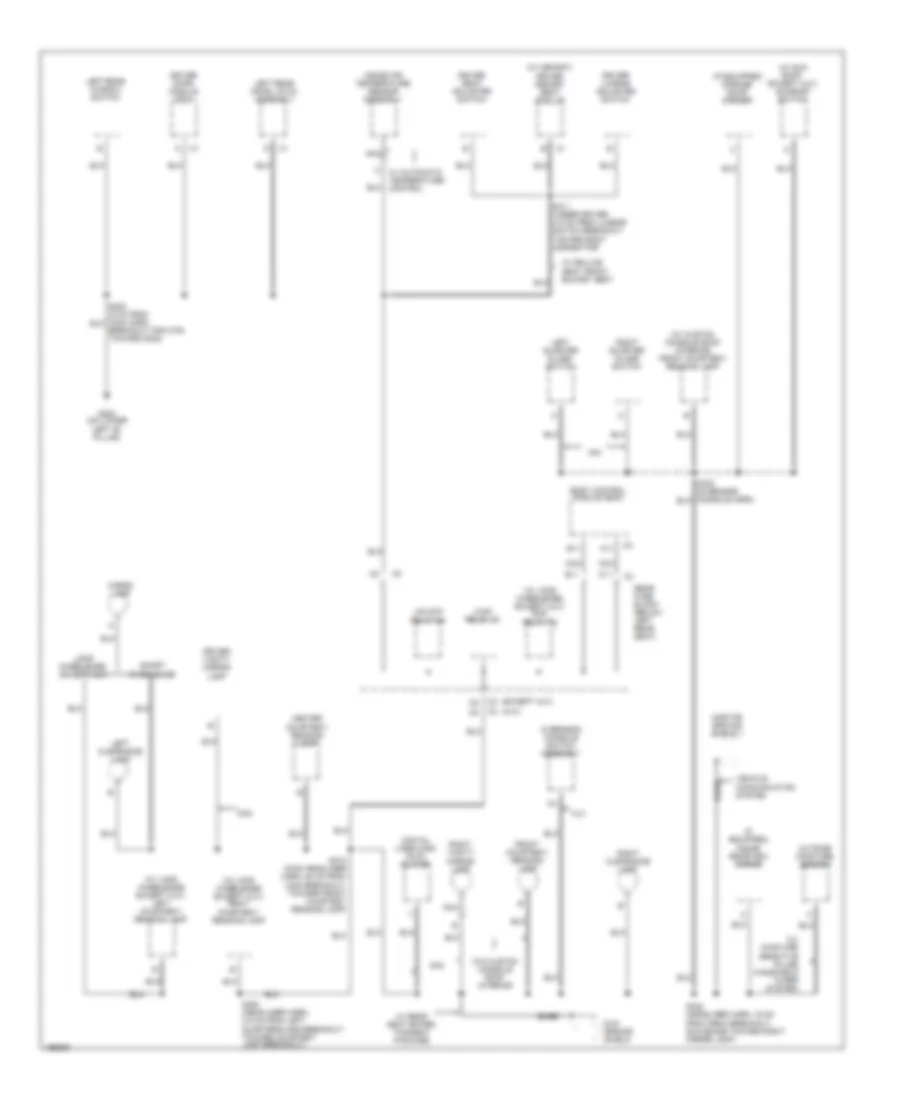 https://portal-diagnostov.com/license.html
Automotive Electricians Portal FZCO
Automotive Electricians Portal FZCO
https://portal-diagnostov.com/license.html
https://portal-diagnostov.com/license.html
Automotive Electricians Portal FZCO
Automotive Electricians Portal FZCOList of elements for Ground Distribution Wiring Diagram (2 of 6) for Chevrolet TrailBlazer 2005:
- (except xuv) c3
- (if equipped) garage door opener
- (if equipped) inside rearview mirror
- (w/ custom console roof interior) front courtesy/ reading lamp
- (w/ long wheelbase except xuv) left courtesy/ reading lamp
- (w/ long wheelbase except xuv) right courtesy/ reading lamp
- (w/ long wheelbase, except xuv) rap relay 22
- (w/ memory) driver memory seat module
- (w/ moisture sensitive pulse windshield wiper system)
- (w/ sun roof, except xuv) sunroof switch
- (xuv) c3
- A11
- A34
- B11
- Bare
- Body control module (bcm)
- Breakout for c700 toward g302)
- Cargo lamp
- Center courtesy/ reading lamp
- Dh2
- Digital video disc (dvd) player
- Driver door module (ddm)
- Driver lumbar adjuster switch
- Driver seat adjuster switch
- Driver vanity mirror lamp
- Dvd ground shield
- Front courtesy/ reading lamp
- G302 (on lower
- Inside air temperature sensor assembly
- Left "b" pillar)
- Left clearance lamp
- Left quarter glass switch
- Left rear door latch assembly
- Left rear window switch
- Lock relay 18
- Long wheelbase, except xuv
- Nca
- Onstar ground shield 1
- Outside moisture sensor
- Overhead console switch assembly
- Rear fuse block (below left rear seat)
- Right clearance lamp
- Right quarter glass switch
- Right vanity mirror lamp
- S311 (under driver 4.5 cm from lumbar switch breakout toward body connector)
- S312 (main headliner harn, 80 cm from c308 breakout, toward front courtesy reading lamp)
- S322 (headliner harn, 16 cm from isrvm breakout, sun shade toward right mirror lamp)
- S350 (headliner harn, 3.5 cm from left quarterglass breakout, toward courtesy lamp breakout)
- Short wheelbase
- Unlock relay 24
- Vehicle communication system
- W/ automatic temperature control
- W/ deluxe seat front bucket seat
- W/ rear seat enter- tainment package
- W/o custom console roof interior
- Xuv
Ground Distribution Wiring Diagram (3 of 6) for Chevrolet TrailBlazer 2005
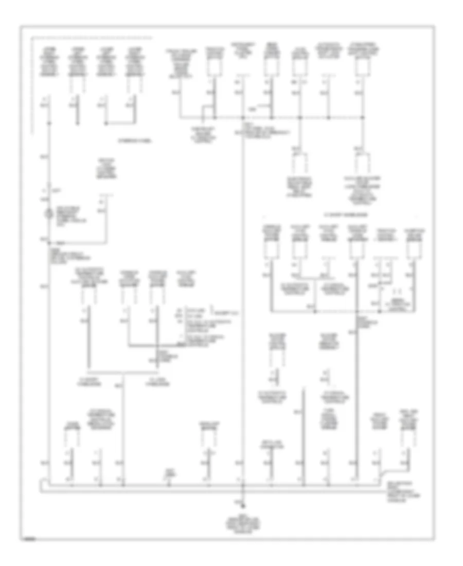 https://portal-diagnostov.com/license.html
Automotive Electricians Portal FZCO
Automotive Electricians Portal FZCO
https://portal-diagnostov.com/license.html
https://portal-diagnostov.com/license.html
Automotive Electricians Portal FZCO
Automotive Electricians Portal FZCOList of elements for Ground Distribution Wiring Diagram (3 of 6) for Chevrolet TrailBlazer 2005:
- (gmc, z89)
- (if equipped) transfer case shift control switch
- (not used)
- (truck trailer hd wiring harness)
- (w/ automatic temperature controls) auxiliary blower motor
- (w/ manual temperature controls) recirulation actuator
- (w/ uk6)
- (w/ xuv, w/ automatic temperature controls)
- (w/ xuv, w/ manual temperature controls)
- (w/o uk6)
- Automatic transmission shift lock actuator
- Auxiliary blower motor (long wheelbase & xuv w/ automatic temperature control)
- Auxiliary console mode actuator
- Auxiliary hvac control module
- B16
- Blower motor control module
- Blower motor resistor assembly
- C277
- Cd6
- Chevrolet/ gmc/z89 w/ traction control
- Cigar lighter
- Console auxiliary power outlet
- Console mode actuator auxiliary
- Data link connector
- Electronic adjustable pedal (eap) relay (if equipped)
- Except xuv
- Front auxiliary power outlet
- G201 (ground splice pack, near right front of lower console)
- Headlamp switch
- Hvac control module
- Ignition lock cylinder control actuator
- Inflatable restraint steering wheel module coil
- Instrument panel cluster (ipc)
- Inverting driver module
- Lower left steering wheel control switch assembly
- Lower right steering wheel control switch assembly
- Nca
- Rear wiper/ washer switch
- S211 (i/p harn, 16 cm from sp 201 breakout, toward dlc)
- S226 (ground circuit splice, in steering column)
- S307 (console harn)
- S309
- Sedan w/ traction control
- Splice pack sp201 (lower right front of lower console)
- Steering wheel
- Traction control switch
- Turn signal/ hazard flasher module
- Upper left steering wheel control switch assembly
- Upper right steering wheel control switch assembly
- W/ automatic temperature controls
- W/ long wheelbase
- W/ manual temperature controls
- W/ short wheelbase
Ground Distribution Wiring Diagram (4 of 6) for Chevrolet TrailBlazer 2005
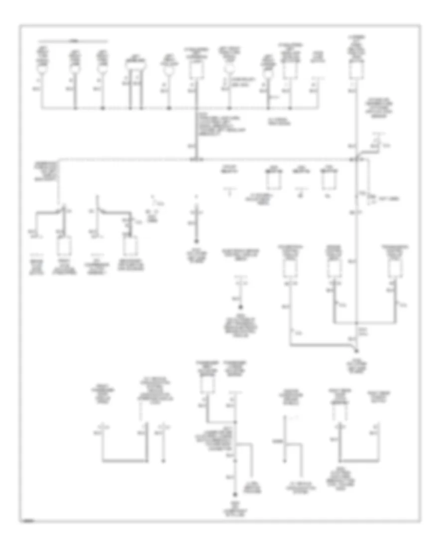 https://portal-diagnostov.com/license.html
Automotive Electricians Portal FZCO
Automotive Electricians Portal FZCO
https://portal-diagnostov.com/license.html
https://portal-diagnostov.com/license.html
Automotive Electricians Portal FZCO
Automotive Electricians Portal FZCOList of elements for Ground Distribution Wiring Diagram (4 of 6) for Chevrolet TrailBlazer 2005:
- (4 speed a/t) park/ neutral position (pnp) switch
- (chevrolet)
- (if equipped) left cornering lamp
- (if equipped) left headlamp leveling actuator
- (not used)
- (w/ vehicle communication system) vehicle communication interface module (vcim)
- (z89, gmc)
- 4.2l
- 5.3l
- A c1
- A/c compressor clutch assembly
- Bare
- Brake fluid level switch
- E5 (not used) c1
- Eap relay 49
- Electronic brake control module (ebcm)
- Engine control module (ecm)
- F/pump relay 41
- Fan relay 45
- Front axle actuator (if equipped)
- Front passenger door module (fpdm)
- G107 (on lower left side of eng)
- G108 (on lower left side of eng)
- G303 (on lower right "b" pillar)
- G304 (on outside of left frame rail, near electronic brake control module)
- Hdm relay 46
- Hood ajar switch
- Intake air temperature (iat)/mass air flow (maf) sensor
- Left front fog lamp
- Left front marker lamp
- Left front park lamp
- Left front park/turn signal lamp
- Left front turn signal lamp
- Left headlamp
- Nca
- Onstar microphone ground shield 2
- Passenger lumbar adjuster switch
- Passenger seat adjuster switch
- Powertrain control module (pcm)
- Right rear door latch assembly
- Right rear window switch
- S101 (5.3l)
- S107 (forward lamp harn, 4.5 cm from left signal breakout, toward left headlamp breakout)
- S303 (5 cm from main harn, breakout for c700, toward g302)
- S317 (under driver 4.5 cm from lumbar switch breakout toward body connector)
- Secondary air injection (air) solenoid
- Transmission control module (tcm)
- Ultra seating package
- Underhood fuse block (on left side of eng compt)
- W/ power adjustable pedal
- W/ vehicle communication system
- W/ wiring provisions
- W49
Ground Distribution Wiring Diagram (5 of 6) for Chevrolet TrailBlazer 2005
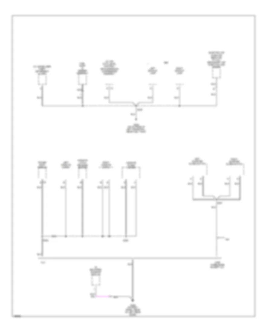 https://portal-diagnostov.com/license.html
Automotive Electricians Portal FZCO
Automotive Electricians Portal FZCO
https://portal-diagnostov.com/license.html
https://portal-diagnostov.com/license.html
Automotive Electricians Portal FZCO
Automotive Electricians Portal FZCOList of elements for Ground Distribution Wiring Diagram (5 of 6) for Chevrolet TrailBlazer 2005:
- (electric air injector reactor w/ 4.2l) secondary air injection (air) pump
- (if equipped) sunroof module
- (w/ air auto level control) air suspension compressor assembly
- (w/ immobilizer) theft deterrent alarm
- A34
- C2 d
- Fuel pump & sender assembly
- G305 (on outside of left frame rail, near fuel tank)
- G306 (on body panel, rear of left rear door)
- Gmc
- Left backup lamp
- Left midgate latch
- Left quarter glass switch
- Long wheelbase except xuv
- Midgate glass motor
- Midgate latch release switch
- Nca
- Power roof module
- Right backup lamp
- Right midgate latch
- Right quarter glass switch
- S306
- S351
- S354
- S355
- Xuv
Ground Distribution Wiring Diagram (6 of 6) for Chevrolet TrailBlazer 2005
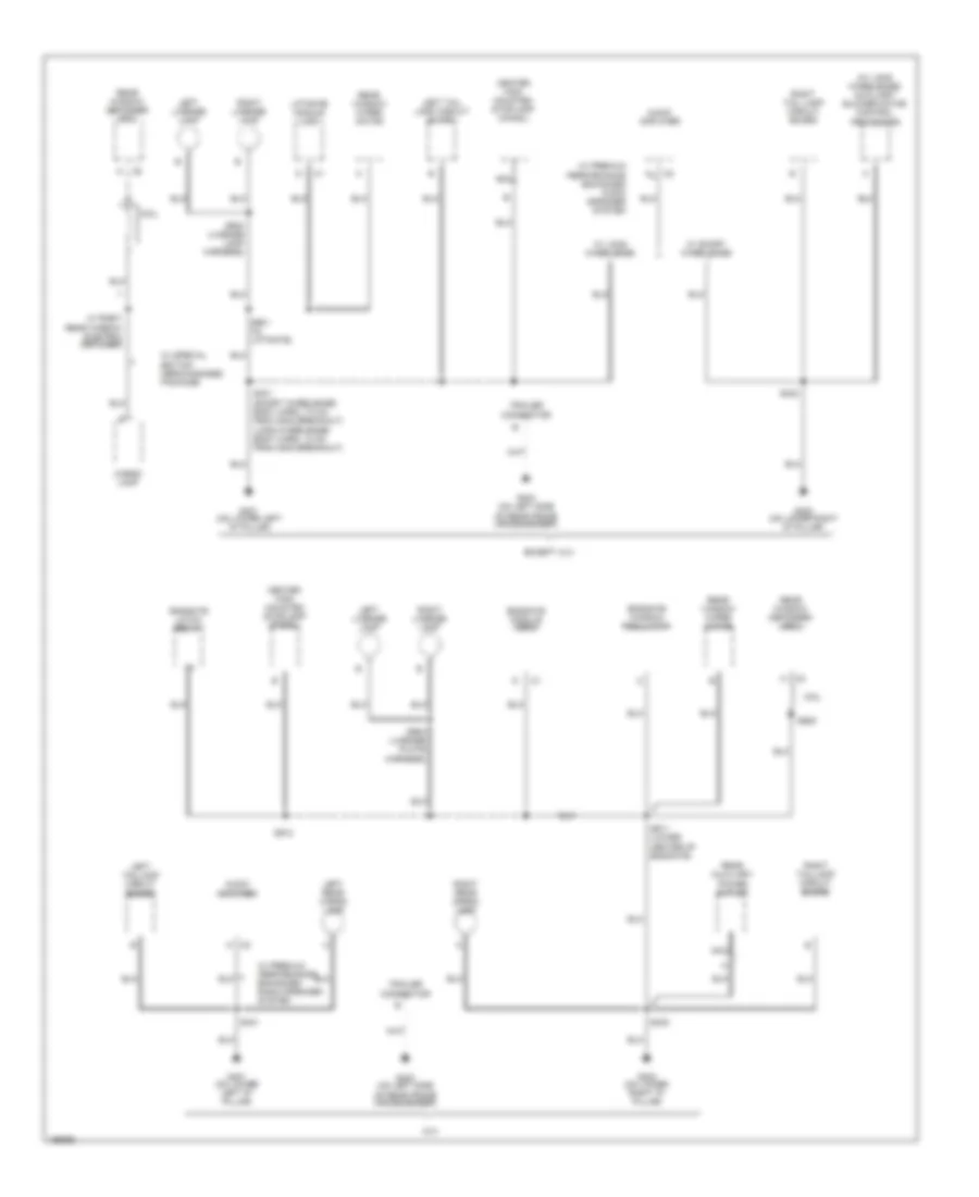 https://portal-diagnostov.com/license.html
Automotive Electricians Portal FZCO
Automotive Electricians Portal FZCO
https://portal-diagnostov.com/license.html
https://portal-diagnostov.com/license.html
Automotive Electricians Portal FZCO
Automotive Electricians Portal FZCOList of elements for Ground Distribution Wiring Diagram (6 of 6) for Chevrolet TrailBlazer 2005:
- xuv
- (w/ long wheelbase) auxiliary blower motor control processor
- Audio amplifier
- Cargo lamp
- Center high mounted stoplamp (chmsl)
- Coil
- Endgate latch relay
- Endgate module (egm)
- Endgate window regulator
- Except xuv
- G401 (on lower left "d" pillar)
- G402 (on lower right "d" pillar)
- G403 (on left side of rear frame crossmember)
- Left license lamp
- Left rear cargo lamp
- Left tail lamp circuit board
- Left taillamp circuit board
- Liftgate module (lgm)
- Nca
- Rear auxiliary power outlet
- Rear window defogger grid
- Rear window wiper motor
- Right license lamp
- Right rear cargo lamp
- Right tail lamp circuit board
- Right taillamp circuit board
- S401
- S401 (short wheelbase: body harn, 7.5 cm from g402 breakout) (long wheelbase: body harn, 13 cm from g402 breakout)
- S402
- S901 (in liftgate)
- S902 (license lamp harness)
- S902 (license plate harness)
- S905
- S911 (lower center of endgate)
- S912
- Trailer connector
- W/ long wheelbase
- W/ premium performance enhanced audio speaker system
- W/ premium performance enhanced radio speaker system
- W/ right rear window electric defogger
- W/ short wheelbase
- W/ special edition merchandised package
HEADLIGHTS
Headlights Wiring Diagram for Chevrolet TrailBlazer 2005
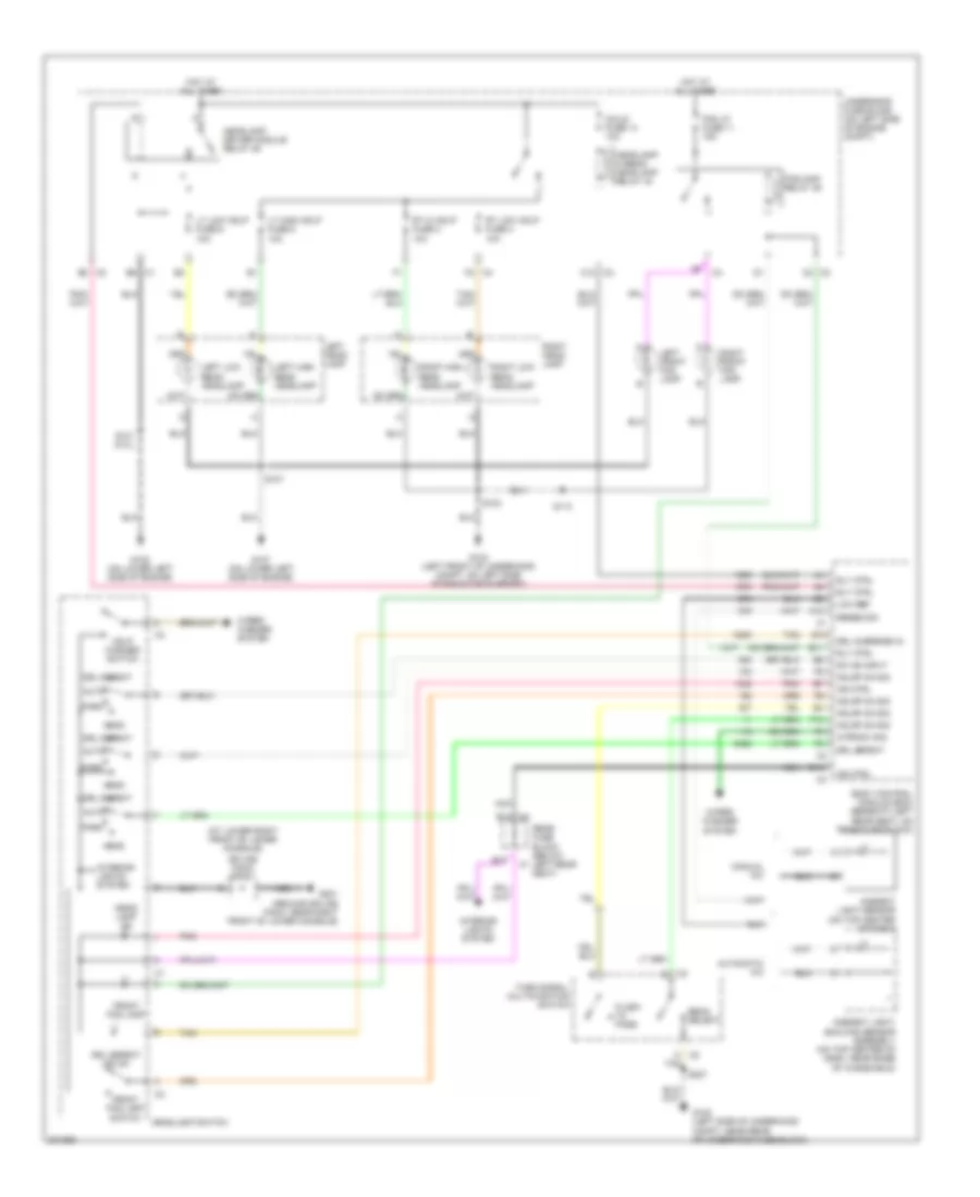 https://portal-diagnostov.com/license.html
Automotive Electricians Portal FZCO
Automotive Electricians Portal FZCO
https://portal-diagnostov.com/license.html
https://portal-diagnostov.com/license.html
Automotive Electricians Portal FZCO
Automotive Electricians Portal FZCOList of elements for Headlights Wiring Diagram for Chevrolet TrailBlazer 2005:
- (at lower right front of lower console)
- A c2
- A12
- Ambient light sensor (on top center of dash)
- Ambient light/ sunload sensor assembly (on top center of dash, near base of windshield)
- Auto
- Automatic a/c
- B10
- B14
- B14 c4
- B3 c2
- Beam select
- Body control module (bcm) (beneath left rear seat, on rear fuse block)
- C12 c2
- C2 c2
- C4 f2
- Coils fuse 14 10a
- Drl defeat
- Drl defeat ind on
- Drl override in.
- E11
- E14
- E6 c1
- F10
- Flash to pass
- Fog lp fuse 11 15a
- Foglamp relay 39
- Front fog lamp
- Front fog lamp switch
- G102 (left side of underhood compt, near rear of underhood fuse block)
- G103 (left front of underhood compt, on left side of radiator support)
- G107 (on lower left side of engine)
- G108 (on lower left side of engine)
- G201 (ground splice pack, near right front of lower console)
- Hdlmp on sig
- Hdlp washer switch
- Head
- Head- lamp on
- Headlamp driver module relay 46
- Headlamp hi-beam headlamp relay 43
- Headlamp switch
- Hot at all times
- Ind ctrl
- Interior lights system
- Left front fog lamp
- Left head- lamp
- Left high beam headlamp
- Left low beam headlamp
- Low ref
- Lt high hdlp fuse 5 10a
- Lt low hdlp fuse 6 10a
- Manual a/c
- Nca
- Park
- Pnk
- Rear fuse block (below left rear seat)
- Right front fog lamp
- Right head- lamp
- Right high beam headlamp
- Right low beam headlamp
- Rly ctrl
- Rt hi hdlp fuse 2 10a
- Rt low hdlp fuse 3 10a
- S101 (5.3l)
- S103
- S107
- S113
- S227
- Sense sig
- Splice pack sp201
- Sw on input
- Tan
- Turn signal/ multifunction switch
- Underhood fuse block (on left side of engine compt)
- Wipe sw sig
- Wiper/ washer system
HORN
Horn Wiring Diagram for Chevrolet TrailBlazer 2005
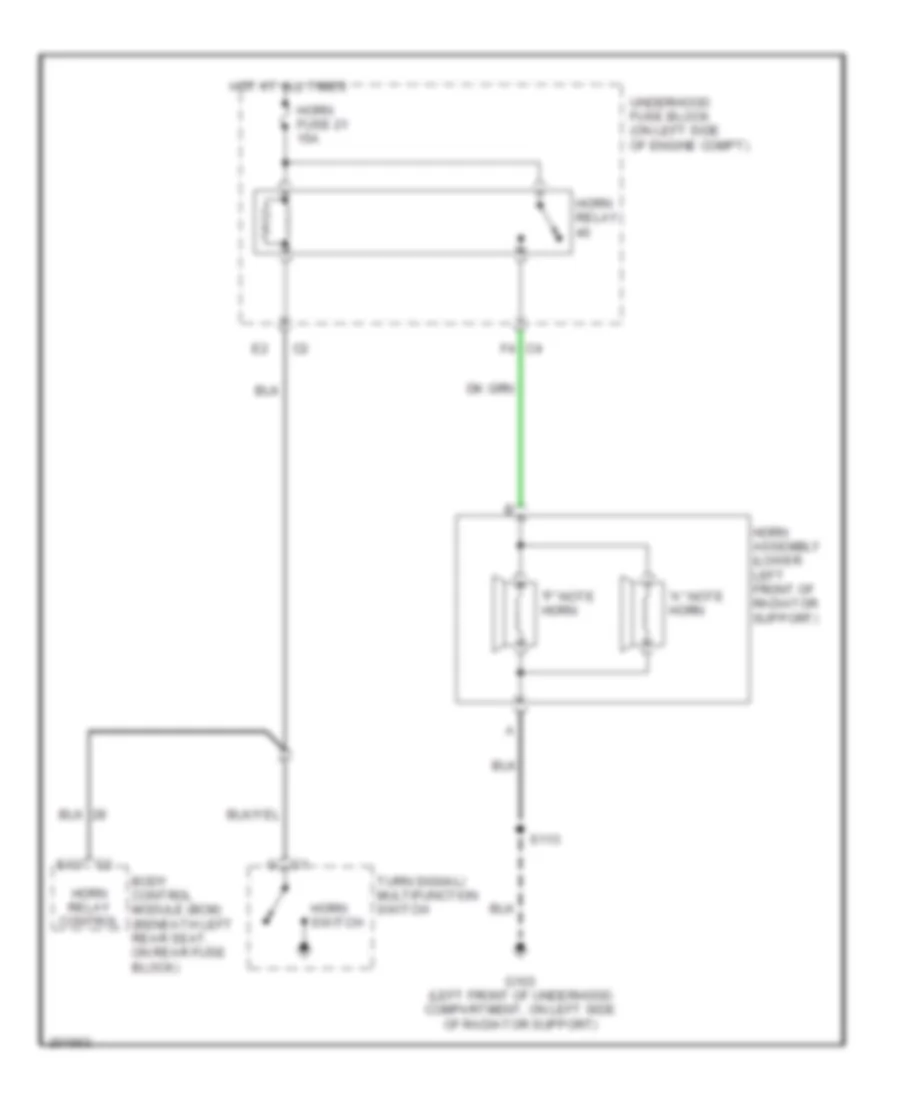 https://portal-diagnostov.com/license.html
Automotive Electricians Portal FZCO
Automotive Electricians Portal FZCO
https://portal-diagnostov.com/license.html
https://portal-diagnostov.com/license.html
Automotive Electricians Portal FZCO
Automotive Electricians Portal FZCOList of elements for Horn Wiring Diagram for Chevrolet TrailBlazer 2005:
- "a" note horn
- "f" note horn
- Body control module (bcm) (beneath left rear seat, on rear fuse block)
- E12
- F4 c4
- G103 (left front of underhood compartment, on left side of radiator support)
- Horn assembly (lower left front of radiator support)
- Horn fuse 21 15a
- Horn relay
- Horn relay control
- Horn switch
- Hot at all times
- S113
- Turn signal/ multifunction switch
- Underhood fuse block (on left side of engine compt)
INSTRUMENT CLUSTER
Instrument Cluster Wiring Diagram for Chevrolet TrailBlazer 2005
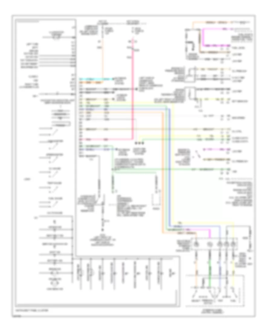 https://portal-diagnostov.com/license.html
Automotive Electricians Portal FZCO
Automotive Electricians Portal FZCO
https://portal-diagnostov.com/license.html
https://portal-diagnostov.com/license.html
Automotive Electricians Portal FZCO
Automotive Electricians Portal FZCOList of elements for Instrument Cluster Wiring Diagram for Chevrolet TrailBlazer 2005:
- (i/p harness, 8.5 cm from c100 breakout, toward underhood fuse block c5 & c6 breakouts) s117
- (left side of underhood compt, near rear of underhood fuse block) g102
- 12v
- 4.2l
- 5 volt ref
- 5.3l
- A10
- A11
- A12
- Abs ind
- Air bag ind
- Air suspension compressor assembly (except xl: behind right rear wheelwell, on frame rail) (xl: on left rear frame rail, near spare tire)
- B10
- B11
- B12
- Batt
- Battery ind
- Brake ind
- Change eng oil ind
- Check gauges ind
- Class 2
- Class 2 data
- Computer data lines system
- Cruise ind
- Dic
- Dic fuel sig
- Dic set/reset
- Dic sw sig
- Dic toggle sw
- Ect sens sig
- Eng speed
- Eng speed sig
- Engine controls system
- Engine coolant temperature (ect) sensor (on left front of engine block, near generator)
- Engine oil pressure (eop) sensor (5.3l) (at rear of engine)
- Engine oil pressure (eop) switch (4.2l) (lower right front of block)
- Exterior lights system
- Fuel
- Fuel gauge
- Fuel level
- Fuel pump & sender assembly (inside fuel tank)
- G103 (left front of underhood compt, on left side of radiator support)
- G201
- Ground
- High beam ind
- Hot at all times
- Hot in run or start
- Ign 1
- Ign e fuse 22 10a
- Illumination (8 bulbs)
- Inflatable restraint steering wheel module coil
- Instrument panel cluster
- Interior lights system
- Ipc/dic fuse 24 10a
- Left turn
- Left turn ind
- Lo washer fluid
- Logic
- Low fuel ind
- Low ref
- Malfunction indicator lamp (service engine soon)
- Mil ctrl
- Nca
- Odometer
- Oil gauge
- Oil pres sig
- Oil press sw
- Personal- ization
- Pnk
- Powertrain control module (pcm) (4.2l) engine control module (ecm) (5.3l) (4.2l: on upper left side of engine) (5.3l: near lower left front of engine)
- Prnd321
- Radio
- Reduce eng power ind
- Right turn
- Right turn ind
- S113
- S202
- S226
- S239
- S359
- Seat belt ind
- Security ind
- Select
- Service 4wd/awd ind
- Shift ind
- Sp201 (at lower right front of lower console)
- Speedometer
- Steering wheel control assembly
- Tachometer
- Tailgate ajar ind
- Temp gauge
- Trip
- Underhood fuse block (on left side of engine compt)
- Volts gauge
- Vss
- Windshield washer fluid level switch (in windshield washer fluid reservoir)
INTERIOR LIGHTS
Courtesy Lamps Wiring Diagram (1 of 2) for Chevrolet TrailBlazer 2005
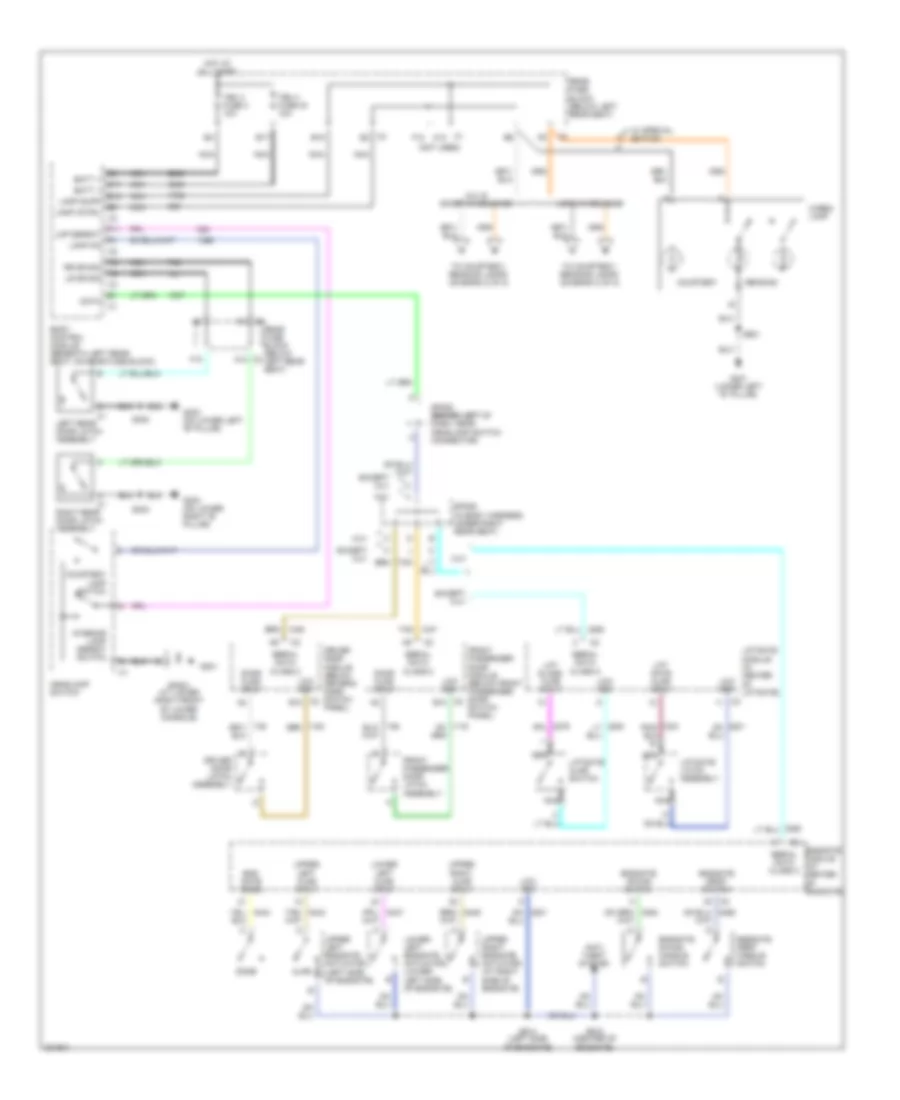 https://portal-diagnostov.com/license.html
Automotive Electricians Portal FZCO
Automotive Electricians Portal FZCO
https://portal-diagnostov.com/license.html
https://portal-diagnostov.com/license.html
Automotive Electricians Portal FZCO
Automotive Electricians Portal FZCOList of elements for Courtesy Lamps Wiring Diagram (1 of 2) for Chevrolet TrailBlazer 2005:
- (not used)
- A12 c2
- Ajar
- Anti- theft system
- B17
- B18
- Batt +
- Body control module (beneath left rear seat, on rear fuse block)
- C1 a12
- C2 b10
- C4 b3
- Cargo lamp
- Courtesy
- Courtesy lamp switch
- Data
- Dome
- Door ajar input
- Driver door latch assembly
- Driver door module (below driver's door switch panel)
- End gate dome
- Endgate drop handle switch
- Endgate drop switch
- Endgate module (at center of endgate)
- Endgate swing handle switch
- Endgate swing switch
- Except xuv
- F10
- F11
- F12
- Front passenger door latch assembly
- Front passenger door module (below front passenger door switch panel)
- G201
- G302 (on lower left "b" pillar)
- G303 (on lower right "b" pillar)
- G401 (lower left "d" pillar)
- Headlamp switch
- Hot at all times
- Interior lamp defeat switch
- Lamp cntrl
- Lamp on
- Lamp supp
- Left rear door latch assembly
- Lift gate ajar input
- Lift glass ajar input
- Liftgate ajar switch
- Liftgate latch assembly
- Liftgate module (in center of liftgate)
- Lmp defeat
- Long wheelbase
- Low ref
- Lower left ajar input
- Lower left endgate actuator (lower left side of endgate)
- Lr dr sig
- Nca
- Reading
- Rear fuse block (below left rear seat)
- Right rear door latch assembly
- Rr dr sig
- S302
- S303
- S901
- S914 (left side of endgate)
- S915 (center of endgate)
- Serial data class 2
- Sp201 (at lower right front of lower console)
- Sp205 (behind left (behind left of dash, near headlamp switch connector)
- Sp306 (in body harness, under right rear seat)
- Tan
- Tbc 3 fuse 4 10a
- Tbc 4 fuse 40 10a
- To courtesy/ reading lamps (diagram 2 of 2)
- Upper left ajar input
- Upper left endgate actuator (left side of endgate)
- Upper right ajar input
- Upper right endgate actuator (at right side of endgate)
- W/ special edition
- Xuv
- Xuv & short wheelbase
Courtesy Lamps Wiring Diagram (2 of 2) for Chevrolet TrailBlazer 2005
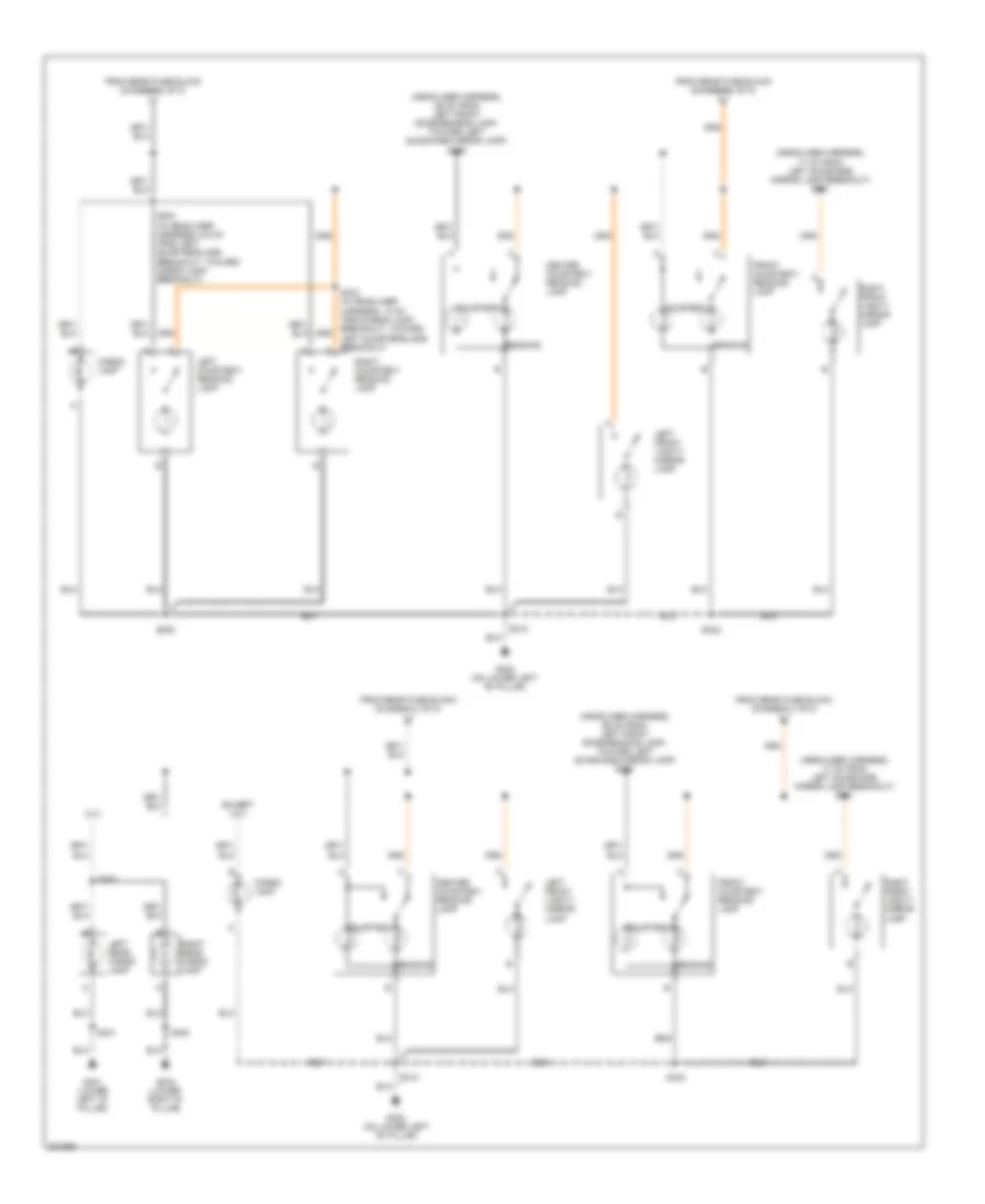 https://portal-diagnostov.com/license.html
Automotive Electricians Portal FZCO
Automotive Electricians Portal FZCO
https://portal-diagnostov.com/license.html
https://portal-diagnostov.com/license.html
Automotive Electricians Portal FZCO
Automotive Electricians Portal FZCOList of elements for Courtesy Lamps Wiring Diagram (2 of 2) for Chevrolet TrailBlazer 2005:
- (headliner harness, 17 cm from left sunshade mirror lamp breakout) s331
- (headliner harness, 26 cm from left front dome/reading lamp, toward left sunshade mirror lamp) s390
- Cargo lamp
- Center courtesy/ reading lamp
- Courtesy
- Except xuv
- From rear fuse block (diagram 1 of 2)
- Front courtesy/ reading lamp
- G302 (on lower left "b" pillar)
- G401 (lower left "d" pillar)
- G402 (lower right "d" pillar)
- Left courtesy/ reading lamp
- Left front vanity mirror lamp
- Left rear cargo lamp
- Reading
- Right courtesy/ reading lamp
- Right front vanity mirror lamp
- Right rear cargo lamp
- S312
- S332
- S333 (in headliner harness, 13 cm from cargo lamp breakout, toward left quarterglass breakout)
- S350
- S353
- S391 (in headliner harness, 6.5 cm from left quarterglass breakout, toward cargo lamp breakout)
- S401
- S402
- Xuv
Instrument Illumination Wiring Diagram (1 of 2) for Chevrolet TrailBlazer 2005
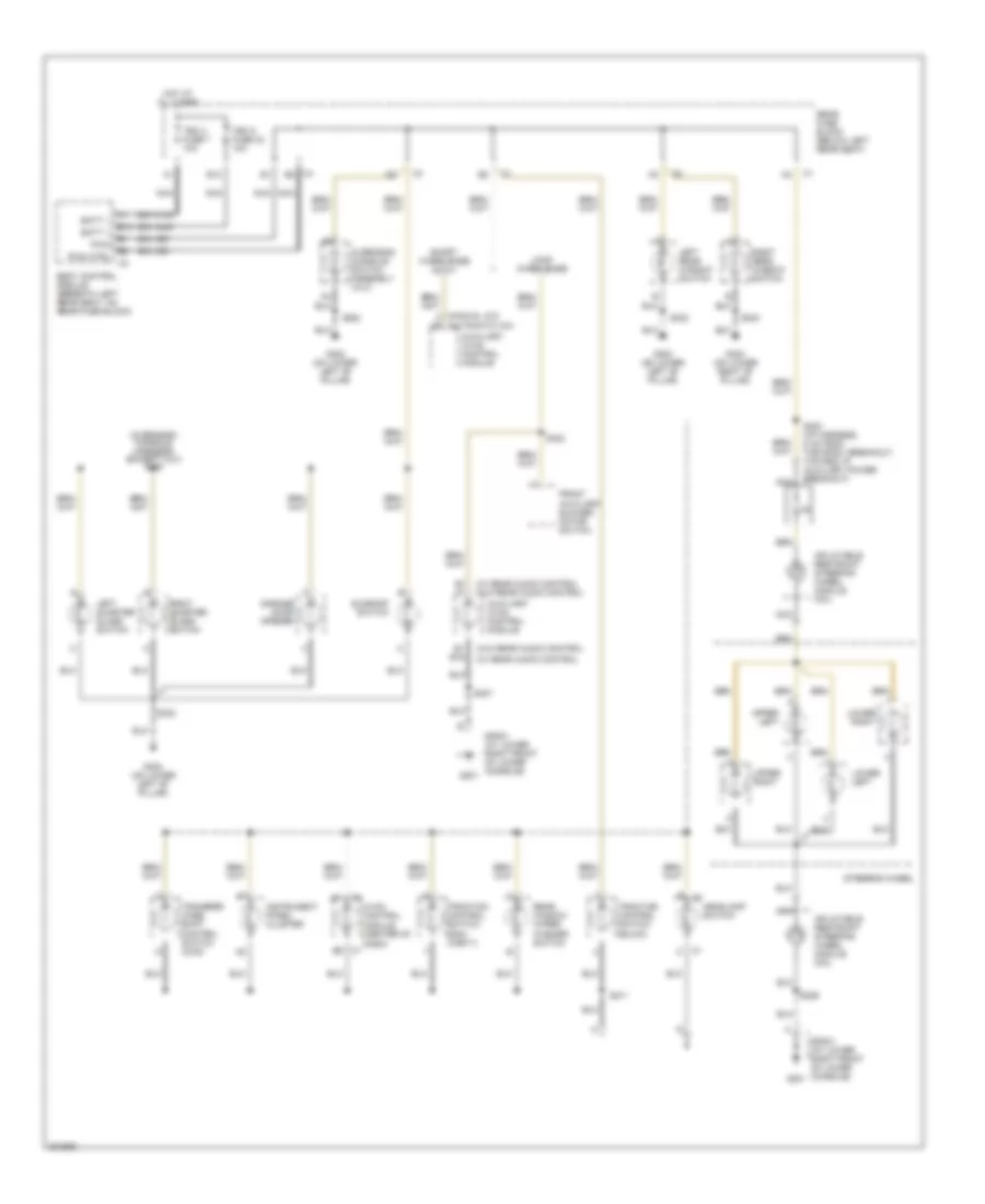 https://portal-diagnostov.com/license.html
Automotive Electricians Portal FZCO
Automotive Electricians Portal FZCO
https://portal-diagnostov.com/license.html
https://portal-diagnostov.com/license.html
Automotive Electricians Portal FZCO
Automotive Electricians Portal FZCOList of elements for Instrument Illumination Wiring Diagram (1 of 2) for Chevrolet TrailBlazer 2005:
- (automatic a/c)
- (manual a/c) a5
- (overhead console harness) (except xuv) s330
- (w/ rear audio control
- (w/ rear audio control (w/o rear audio control
- (w/o rear audio control
- Auxiliary hvac control module
- B c1
- B1 a1
- B1 b16
- B13
- B9 c1
- Batt +
- Body control module (beneath left rear seat, on rear fuse block)
- C1 c
- C4 b2
- Front auxiliary blower motor switch
- G201
- G302 (on lower left "b" pillar)
- G303 (on lower right "b" pillar)
- Garage door opener
- Headlamp switch
- Hot at all times
- Hvac control module (center of dash)
- Inflatable restraint steering wheel module coil
- Instrument panel cluster
- Left quarter glass switch
- Left rear window switch
- Long wheelbase
- Lower left
- Lower right
- Nca
- Overhead console switch assembly (xuv)
- Pwm
- Pwm ctrl
- Rear fuse block (below left rear seat)
- Rear window wiper/ washer switch
- Right quarter glass switch
- Right rear window switch
- S211
- S226
- S230 (i/p harness, 5 cm from the sp201 breakout, toward i/p auxiliary power breakout)
- S302
- S303
- S307
- S322
- S323
- S332
- Short wheelbase & xuv
- Sp201 (at lower right front of lower console)
- Steering wheel
- Sunroof switch
- Tbc 2 fuse 7 10a
- Tbc 5 fuse 32 10a
- Traction control switch (buick)
- Traction control switch (gmc, chevy)
- Transfer case shift control switch (4wd)
- Upper left
- Upper right
Instrument Illumination Wiring Diagram (2 of 2) for Chevrolet TrailBlazer 2005
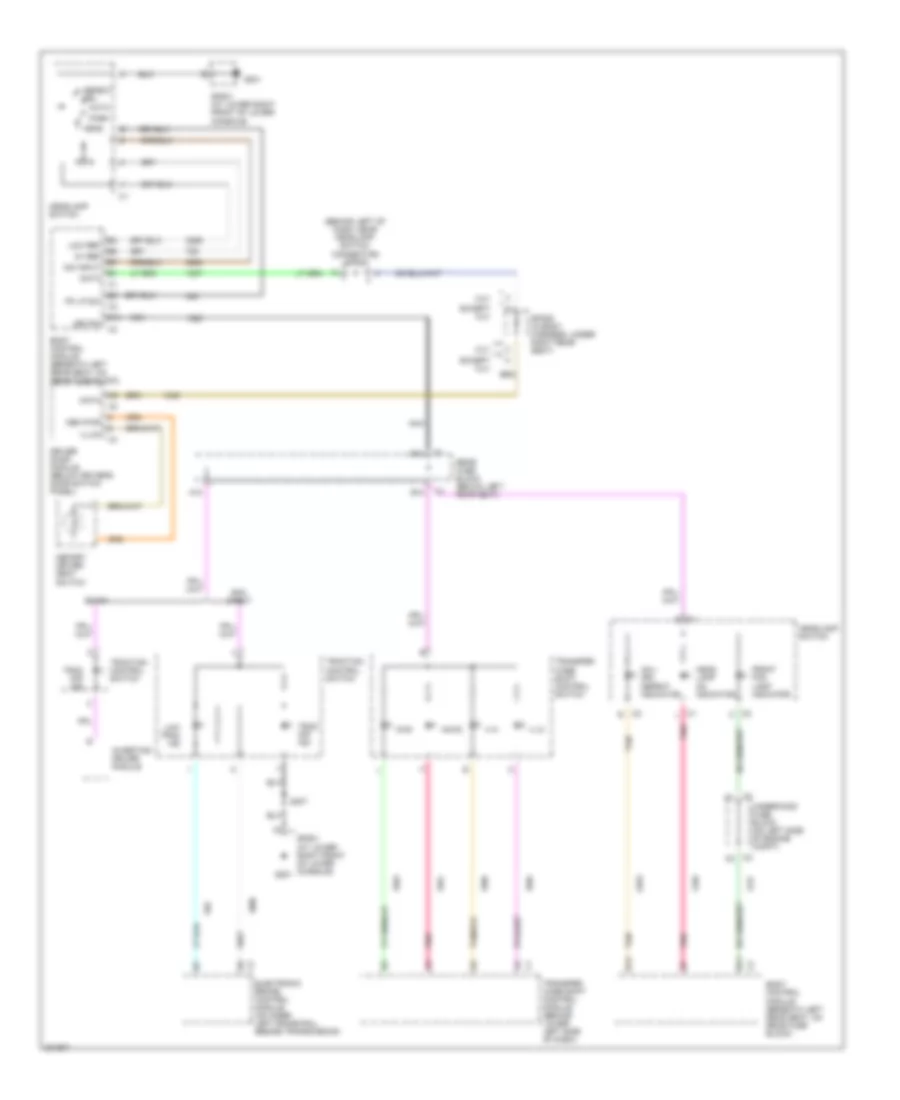 https://portal-diagnostov.com/license.html
Automotive Electricians Portal FZCO
Automotive Electricians Portal FZCO
https://portal-diagnostov.com/license.html
https://portal-diagnostov.com/license.html
Automotive Electricians Portal FZCO
Automotive Electricians Portal FZCOList of elements for Instrument Illumination Wiring Diagram (2 of 2) for Chevrolet TrailBlazer 2005:
- (behind left of dash, near headlamp switch connector) sp205
- 2wd
- 4 hi
- 4 lo
- 5v ref
- A10
- A4wd
- Ahl/ drl defeat indicator
- Auto
- B10
- B14
- Body control module (beneath left rear seat, on rear fuse block)
- Buick
- C1 l
- C2 c
- C2 c2
- C2 e
- Data
- Defeat drl
- Dim input
- Driver door module (below driver's door switch panel)
- E11
- E14
- Electronic brake control module (on inner left frame rail, beside transmission)
- Except xuv
- Front fog lamp indicator
- G201
- Gmc, chevy
- Head
- Head lamp on indicator
- Headlamp switch
- Illum
- Inverting driver module
- K c1
- Led dim
- Low ref
- Low trac ind
- Mem pwr
- Memory driver seat switch
- Nca
- Park
- Pk lp sw
- Pnk
- Rear fuse block (below left rear seat)
- S307
- Sp201 (at lower right front of lower console)
- Sp201 (at lower right front of lower console)
- Sp306 (in body harness, under right rear seat)
- Tan
- Trac off ind
- Traction control switch
- Transfer case shift control module (behind lower left side of dash)
- Transfer case shift control switch
- Underhood fuse block (on left side of engine compt)
- Xuv
MEMORY SYSTEMS
Adjustable Pedal Wiring Diagram for Chevrolet TrailBlazer 2005
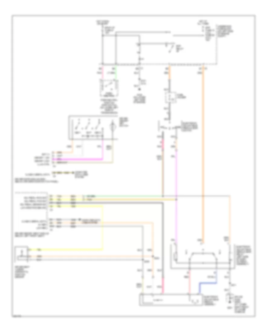 https://portal-diagnostov.com/license.html
Automotive Electricians Portal FZCO
Automotive Electricians Portal FZCO
https://portal-diagnostov.com/license.html
https://portal-diagnostov.com/license.html
Automotive Electricians Portal FZCO
Automotive Electricians Portal FZCOList of elements for Adjustable Pedal Wiring Diagram for Chevrolet TrailBlazer 2005:
- 5v ref
- Adj pedal fwd sig
- Adj pedal rwd sig
- Adj pedal sensor sig
- Aft
- B10
- Back up fuse 27 15a
- Bat (+)
- C1 e6
- C2 e7
- Class 2 serial data
- Computer data lines system
- Driver door module (ddm) (below driver's door switch panel)
- Driver memory seat module (below left front seat)
- Driver memory set switch
- Driver seat lumbar horizontal position sensor
- Eap fuse 15 (4.2l) fuse 59 (5.3l) 15a
- Eap relay
- Electronic adjustable pedals (eap) relay (left side of dash, on pedal assembly)
- Electronic adjustable pedals (eap) switch
- Electronic adjustable pedals assembly
- Exit
- Fore
- Fuse holder
- G108 (on lower left side of engine)
- G201
- Hot at all times
- Hot in run or start
- Illum ctrl
- Low ref
- Lum horiz pos sen sig
- Mem 1
- Mem 2
- Memory 1 sw
- Memory 2 sw
- Nca
- Park/ neutral
- Park/neutral position (pnp) switch (on lower left side of transmission)
- Pnk
- Red
- S101 (5.3l)
- S211
- S304
- S305
- Splice pack sp201 (at lower right front of lower console)
- Tan
- Underhood fuse block (on left side of engine compt)
Driver"s Memory Seat Wiring Diagram for Chevrolet TrailBlazer 2005
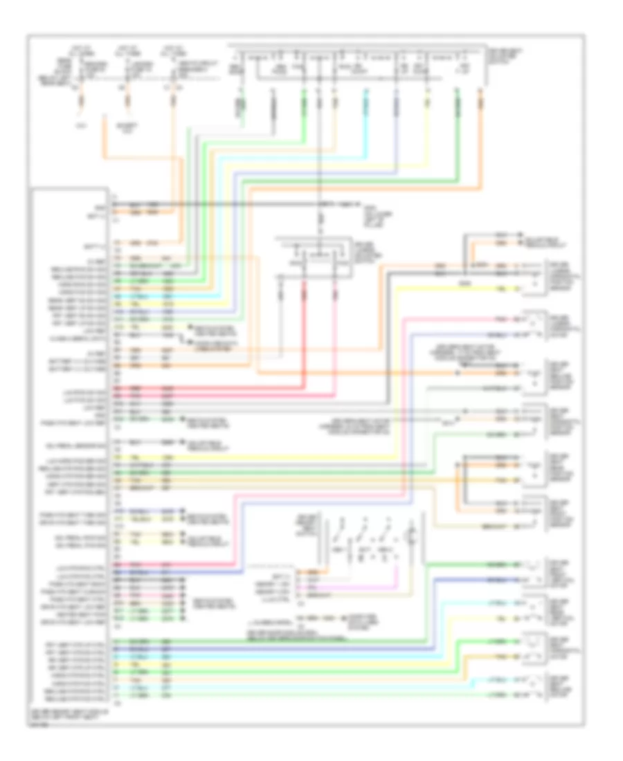 https://portal-diagnostov.com/license.html
Automotive Electricians Portal FZCO
Automotive Electricians Portal FZCO
https://portal-diagnostov.com/license.html
https://portal-diagnostov.com/license.html
Automotive Electricians Portal FZCO
Automotive Electricians Portal FZCOList of elements for Driver"s Memory Seat Wiring Diagram for Chevrolet TrailBlazer 2005:
- (driver's seat motor harness, 17 cm from seat module connector c2) s313
- (driver's seat motor harness, 24 cm from seat module connector c2)
- 5v ref
- A10
- A11
- A12
- Adj pedal fwd sig
- Adj pedal rwd sig
- Adj pedal sensor sig
- Adjustable pedals circuit
- B10
- B11
- B12
- Bat (+)
- Batt (+)
- Battery (+) voltage
- C2 c1
- Class 2 data
- Class 2 serial data
- Computer data lines system
- D tan
- Driver door module (ddm) (below driver's door switch panel)
- Driver lumbar adjuster switch
- Driver lumbar horizontal motor
- Driver lumbar horizontal position sensor
- Driver memory seat module (below left front seat)
- Driver memory seat switch
- Driver seat adjuster switch
- Driver seat front position sensor
- Driver seat front vertical motor
- Driver seat horizontal motor
- Driver seat horizontal position sensor
- Driver seat rear position sensor
- Driver seat rear vertical motor
- Driver seat recline motor
- Driver seat recline position sensor
- Drvr htd seat low ref
- Drvr htd seat them sig
- Egm/dsm fuse 23 10a
- Except xuv
- Exit
- F red
- Frt dwn
- Frt up
- Frt vert dn sw sig
- Frt vert mtr dn ctrl
- Frt vert mtr pos sen
- Frt vert mtr up ctrl
- Frt vert up sw sig
- Fwd
- G302 (on lower left "b" pillar)
- Gnd
- Heated seat pwr
- Horiz fwd sw sig
- Horiz mtr fwd ctrl
- Horiz mtr pos sen sig
- Horiz mtr rwd ctrl
- Horiz rwd sw sig
- Hot at all times
- Illum ctrl
- Lgm/dsm fuse 19 10a
- Low ref
- Lum fwd sw sig
- Lum horiz pos sen sig
- Lum mtr fwd ctrl
- Lum mtr rwd ctrl
- Lum rwd sw sig
- Mem 1
- Mem 2
- Memory 1 sw
- Memory 2 sw
- Pass htd seat back
- Pass htd seat ctrl
- Pass htd seat cushion
- Pass htd seat low ref
- Pass htd seat them sig
- Pnk
- Rear fuse block (below left rear seat)
- Rear vert dn sw sig
- Rear vert up sw sig
- Rec fwd
- Rec rwd
- Recline fwd sw sig
- Recline mtr fwd ctrl
- Recline mtr pos sen sig
- Recline mtr rwd ctrl
- Recline rwd sw sig
- Red
- Rr dwn
- Rr up
- Rr vert mtr dn ctrl
- Rr vert mtr up ctrl
- Rwd
- S304
- S305
- S311
- S314
- Seats circuit breaker 8 30a
- Seats system (heated seats)
- Tan
- Vert mtr pos sen sig
- Xuv
Memory Mirrors Wiring Diagram for Chevrolet TrailBlazer 2005
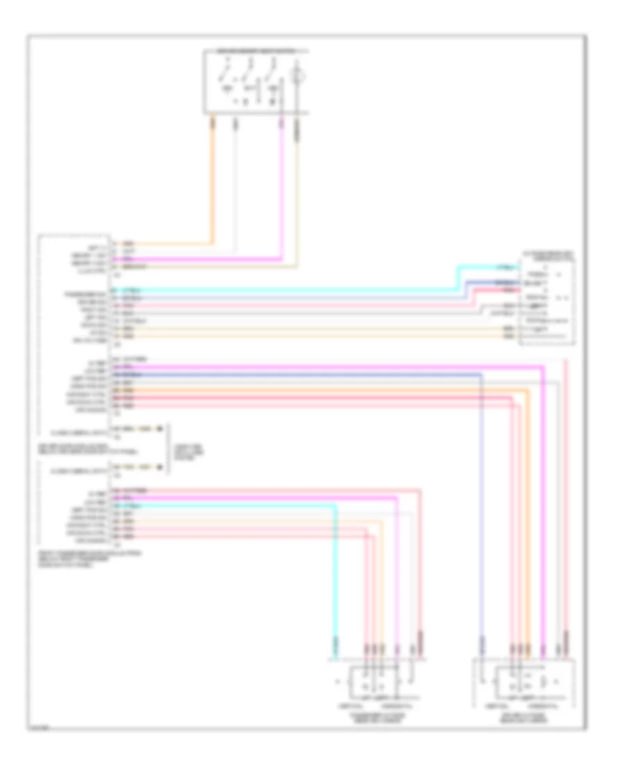 https://portal-diagnostov.com/license.html
Automotive Electricians Portal FZCO
Automotive Electricians Portal FZCO
https://portal-diagnostov.com/license.html
https://portal-diagnostov.com/license.html
Automotive Electricians Portal FZCO
Automotive Electricians Portal FZCOList of elements for Memory Mirrors Wiring Diagram for Chevrolet TrailBlazer 2005:
- 5v ref
- Bat (+)
- Class 2 serial data
- Computer data lines system
- Down
- Down sig
- Driver
- Driver door module (ddm) (below driver's door switch panel)
- Driver memory seat switch
- Driver outside rearview mirror
- Driver sig
- Exit
- Front passenger door module (fpdm) (below front passenger door switch panel)
- Horiz pos sig
- Horizontal
- Ign voltage
- Illum ctrl
- Left
- Left sig
- Low ref
- Mem
- Memory 1 sw
- Memory 2 sw
- Mir common
- Mir down ctrl
- Mir right ctrl
- Outside rearview mirror switch
- Pass
- Passenger outside rearview mirror
- Passenger sig
- Pnk
- Red
- Right
- Right sig
- Tan
- Up sig
- Vert pos sig
- Vertical
POWER DISTRIBUTION
Power Distribution Wiring Diagram (1 of 6) for Chevrolet TrailBlazer 2005
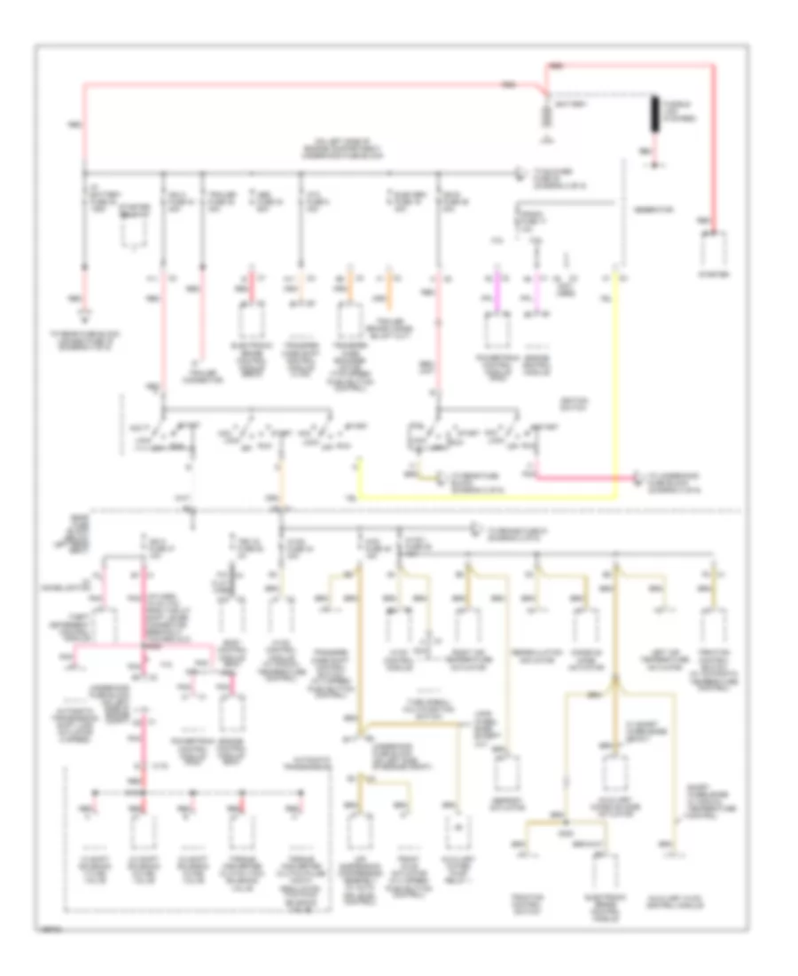 https://portal-diagnostov.com/license.html
Automotive Electricians Portal FZCO
Automotive Electricians Portal FZCO
https://portal-diagnostov.com/license.html
https://portal-diagnostov.com/license.html
Automotive Electricians Portal FZCO
Automotive Electricians Portal FZCOList of elements for Power Distribution Wiring Diagram (1 of 6) for Chevrolet TrailBlazer 2005:
- (i/p harn, pnk 18 cm (7in) from the a/t shift lever connector breakout, toward dlc) s320
- (not used)
- (on left side of engine compartment) underhood fuse block
- 1-2 shift solenoid (1-2 ss) valve
- 2-3 shift solenoid (2-3 ss) valve
- 3-2 shift solenoid 3-2 ss) valve
- 4.2l
- 4wd fuse 48 15a
- 5.3l
- A11
- A18
- Abs fuse 33 60a
- Acc
- Air suspension compressor assembly (w/ auto air level control)
- Atc fuse 8 30a
- Automatic transmission
- Automatic transmission shift lock actuator (4 speed)
- Auxiliary console mode actuator
- Auxiliary hvac control module
- Auxiliary water pump relay 1
- B11
- Battery
- Body control module (bcm)
- C175
- C2 underhood fuse block (on left side of engine compt)
- Console mode actuator
- Crank fuse 17 10a
- D9 c1
- Defrost actuator
- Electronic brake control module
- Electronic brake control module (ebcm)
- Elek brk fuse 19 30a
- Engine control module
- Engine control module (ecm)
- F11
- Flat- wire
- Front axle actuator (w/ 2 speed push button control)
- Fusible link (8 ga-red)
- Generator
- Hvac control module
- Hvac control module (w/ manual temperature control)
- Hvac fuse 44 30a
- Hvac i fuse 39 10a
- I/p battery fuse 48 125a
- Ign a fuse 34 40a
- Ign b fuse 36 40a
- Ign o fuse 47 10a
- Ignition switch
- Left air temperature actuator
- Lock
- Long wheel base except xuv
- Nca
- Off
- Pnk
- Powertrain control module (pcm)
- Rear fuse block (below left rear seat)
- Recirculation actuator
- Red
- Red f
- Right air temperature actuator
- Run
- S133
- S300
- Short wheelbase w/ manual temperature control
- Start
- Starter
- Starter relay 47
- Tbc ig fuse 50 3a
- Theft deterrent control module
- To blower fuse 35 (diagram 2 of 6)
- To brake fuse 51 (diagram 2 of 6)
- To rear fuse block (diagram 2 of 6)
- To rear fuse block lgm/dsm fuse 19 (diagram 4 of 6)
- To underhood fuse block (diagram 3 of 6)
- Torque converter clutch (tcc) solenoid valve
- Torque converter clutch pulse width modulation (tcc pwm) solenoid valve
- Traction control switch
- Traction control switch (w/ automatic temperature control)
- Trailer connector
- Trailer fuse 32 30a
- Transfer case encoder motor (two speed push button control)
- Transfer case shift control module (4 wd)
- Transfer case shift control switch (w/ 2 speed push button control)
- Turn signal/ multifunction switch
- Underhood fuse block (on left side of engine compt)
- W/ immobilization
- W/ short wheelbase or xuv
Power Distribution Wiring Diagram (2 of 6) for Chevrolet TrailBlazer 2005
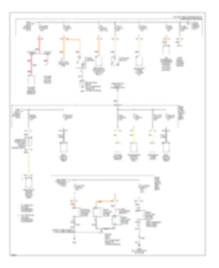 https://portal-diagnostov.com/license.html
Automotive Electricians Portal FZCO
Automotive Electricians Portal FZCO
https://portal-diagnostov.com/license.html
https://portal-diagnostov.com/license.html
Automotive Electricians Portal FZCO
Automotive Electricians Portal FZCOList of elements for Power Distribution Wiring Diagram (2 of 6) for Chevrolet TrailBlazer 2005:
- (4.2l)
- (long wheel base)
- (on left side of engine compt) underhood fuse block
- (short wheel base) m e
- A20
- Air fuse 56 60a
- Air suspension compressor assembly (w/ auto air level control)
- Aux pwr 1 fuse 46 20a
- Aux pwr 2 fuse 15 20a (xuv)
- B10
- B15
- Blower fuse 35 40a
- Blower motor control module
- Blower motor resistor assembly
- Body control module (bcm)
- Brake fuse 51 10a
- C11
- Cigar fuse 13 20a
- Cigar lighter
- Console auxiliary power outlet
- Data link connector (dlc)
- E10
- Ecas fuse 1 30a
- Electronic brake control module (bcm)
- Flash fuse 52 25a
- Flat- wire
- From b ign b fuse 36 (diagram 1 of 6)
- From c hvac i fuse 39 (diagram 1 of 6)
- From ignition switch (diagram 1 of 6)
- From rear l fuse block (diagram 4 of 6)
- Front auxiliary power outlet
- Frt wpr fuse 33 25a
- G201
- G402 (on lower right "d" pillar)
- Instrument panel cluster (ipc)
- Ipc/dic fuse 24 10a
- Nca
- Outside moisture sensor
- Rain fuse 29 10a
- Rear auxiliary power outlet (xuv) (left rear body side lower trim panel)
- Rear fuse block (below left rear seat)
- Red
- S250
- S307
- S402
- Secondary air injection (air) pump relay
- Splice pack sp201 (at lower right front of lower console)
- St/lp fuse 12 25a
- Stoplamp switch
- Tbc acc fuse 31 3a
- Tbc run fuse 52 3a
- Tcm fuse 35 10a
- To ecm fuse 29 (diagram 3 of 6)
- Transmission control module (5.3l)
- Turn signal/ hazard flasher module
- Underhood fuse block (on left side of engine compt)
- W/ auto hvac
- W/ gmc conversion name plt
- W/ manual hvac
- W/ traction control powertrain management
- W/o traction control powertrain management
- Windshield wiper motor
Power Distribution Wiring Diagram (3 of 6) for Chevrolet TrailBlazer 2005
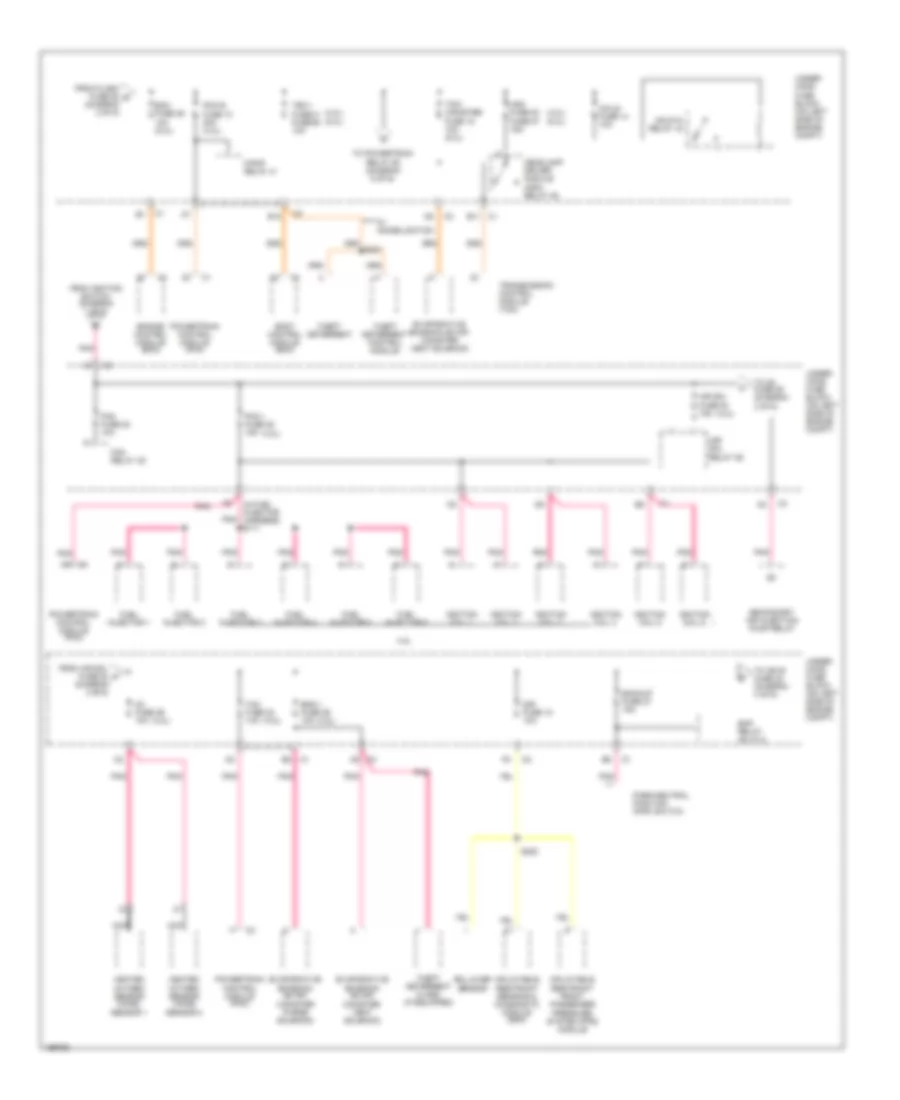 https://portal-diagnostov.com/license.html
Automotive Electricians Portal FZCO
Automotive Electricians Portal FZCO
https://portal-diagnostov.com/license.html
https://portal-diagnostov.com/license.html
Automotive Electricians Portal FZCO
Automotive Electricians Portal FZCOList of elements for Power Distribution Wiring Diagram (3 of 6) for Chevrolet TrailBlazer 2005:
- (4.2l)
- (4.2l) (5.3l)
- (in fuel injector harness) s111
- (jf 4)
- 4.2l
- Air sol fuse 54 15a
- Air sol relay 55
- B11
- Backup fuse 27 15a
- Body control module (bcm)
- Coils fuse 14 10a
- E12
- Eap relay
- Ecm fuse 29 10a (5.3l)
- Eng 1 fuse 26 10a
- Engine control module (ecm)
- Evaporative emission (evap) canister purge solenoid
- Evaporative emission (evap) canister vent solenoid
- F/pmp relay 41
- Fan fuse 20 10a
- Fan relay 45
- From air sol fuse 54 f (diagram 3 of 6)
- From flash fuse 52 d (diagram 2 of 6)
- From ignition switch (diagram 1 of 6)
- Fuel injector 1
- Fuel injector 2
- Fuel injector 3
- Fuel injector 4
- Fuel injector 5
- Fuel injector 6
- Hdlp-hi relay 43
- Hdm fuse 53 fuse 57 15a
- Headlamp driver module (hdm) relay 46
- Heated oxygen sensor (ho2s) sensor 1
- Heated oxygen sensor (ho2s) sensor 2
- Ignition coil 1
- Ignition coil 2
- Ignition coil 3
- Ignition coil 4
- Ignition coil 5
- Ignition coil 6
- Inflatable restraint front passenger pressure system (pps) module
- Inflatable restraint sensing & diagnostic module (sdm)
- Nca
- O2 fuse 29 10a
- Park/neutral position (pnp) switch
- Pcm b fuse 10 20a (4.2l)
- Pcm i fuse 28 15a
- Pnk
- Powertrain control module (pcm)
- Rollover sensor
- S220
- S321
- Secondary air injection pump relay
- Sir fuse 18 10a
- Tac fuse 23 10a
- Tbc 1 fuse 31 fuse 58 10a
- Tcm/ canister fuse 15 10a (5.3l)
- Theft deterrent
- Theft deterrent alarm (if equipped)
- Theft deterrent control module
- To ign e fuse 22 (diagram 4 of 6)
- To o2 fuse 29 (diagram 3 of 6)
- To powertrain relay 60 (diagram 6 of 6)
- Transmission control module (tcm)
- Under- hood fuse block (on left side of engine compt)
- W/ immobilization
Power Distribution Wiring Diagram (4 of 6) for Chevrolet TrailBlazer 2005
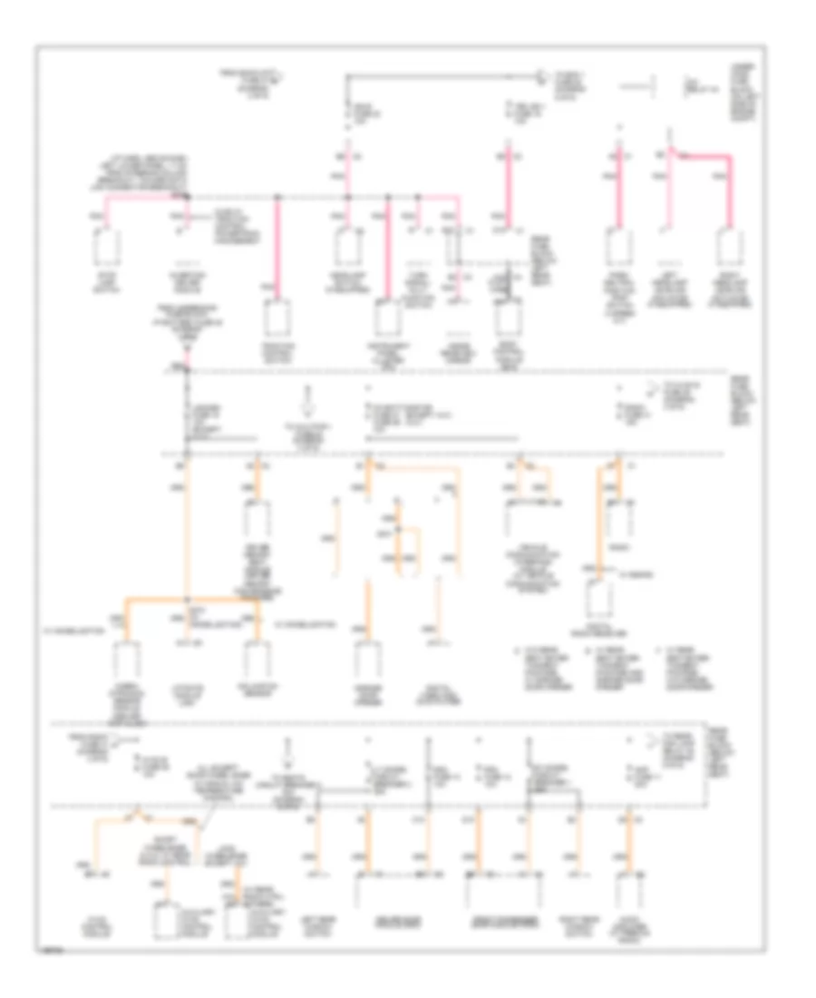 https://portal-diagnostov.com/license.html
Automotive Electricians Portal FZCO
Automotive Electricians Portal FZCO
https://portal-diagnostov.com/license.html
https://portal-diagnostov.com/license.html
Automotive Electricians Portal FZCO
Automotive Electricians Portal FZCOList of elements for Power Distribution Wiring Diagram (4 of 6) for Chevrolet TrailBlazer 2005:
- (except xuv) (xuv)
- (i/p harn, above dash left lower panel, 11 cm from steering column breakout, toward data link connector breakout) s239
- (w/ rear radio ctrl) (others)
- A/c relay 44
- A16 a2
- A19
- A19 flat- wire
- All except shor wheel base w/ manual a/c temperature control
- Amp fuse 11 20a
- Audio amplifier (w/ premium radio)
- Auxiliary hvac control module
- Body control module (bcm)
- C10
- Cobra intrusion sensor module (dealer installed)
- Communication system)
- D10
- D12
- Ddm fuse 10 10a
- Digital radio receiver
- Digital video disc (dvd) player
- Driver door module (ddm)
- Driver memory seat module (driver memory convenience package)
- E12
- From back-up fuse 27 g (diagram 3 of 6)
- From radio fuse 41 h (diagram 4 of 6)
- From underhood fuse block, i/p battery fuse 48 (diagram 1 of 6)
- Front passenger door module (fpdm)
- Garage door opener
- Headlamp switch (if equipped)
- Hvac b fuse 36 10a
- Hvac control module
- Ign e fuse 22 10a
- Immobilization)
- Inclination sensor
- Inside rearview mirror
- Instrument panel cluster (ipc)
- Inverting driver module
- Left headlamp leveling actuator (if equipped)
- Left rear window switch
- Lgm/dsm fuse 19 10a (except xuv)
- Liftgate module (lgm)
- Long wheelbase except xuv
- Lt doors circuit breaker 2 25a
- Oh batt/onstar fuse 27 fuse 26 10a
- Olds w/ traction control powertrain management
- Park/ neutral position (pnp) switch (4 speed a/t)
- Pdm fuse 12 10a
- Pnk
- Radio
- Radio fuse 41 15a
- Rear fuse block (below left rear seat)
- Red
- Right headlamp leveling actuator (if equipped)
- Right rear window switch
- Rt doors circuit breaker 1 25a
- S341
- Seat enter- tainment package and garage door opener
- Seat enter- tainment package, w/ garage door opener
- Seat enter- tainment package, w/o garage door opener
- Short wheelbase & xuv w/ rear radio control
- Stop lamp switch
- Tbc ign 1 fuse 16 10a
- To aux pwr 1 fuse 46 (diagram 2 of 6)
- To ecm 1 fuse 28 (diagram 5 of 6)
- To hvac b fuse 36 (diagram 4 of 6)
- To rear fog lamp relay 45 (diagram 5 of 6)
- To seats circuit breaker 8 30a (diagram 6 of 6)
- Traction control switch
- Turn signal/ mult- function switch
- Under- hood fuse block (on left side of engine compt)
- Vehicle communication interface module (w/ vehicle
- W/ immobilization
- W/ rear e
- W/ rear f
- W/ s-band
- W/o rear d
Power Distribution Wiring Diagram (5 of 6) for Chevrolet TrailBlazer 2005
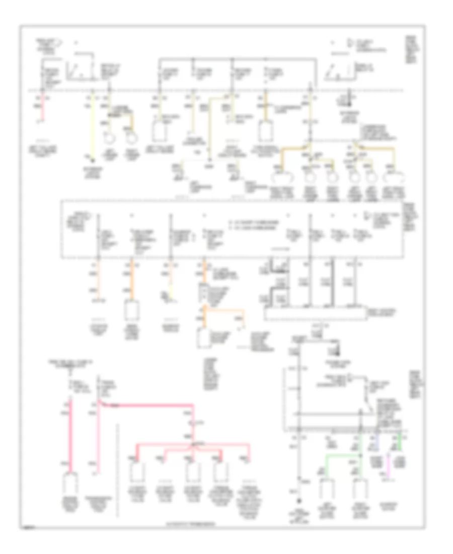 https://portal-diagnostov.com/license.html
Automotive Electricians Portal FZCO
Automotive Electricians Portal FZCO
https://portal-diagnostov.com/license.html
https://portal-diagnostov.com/license.html
Automotive Electricians Portal FZCO
Automotive Electricians Portal FZCOList of elements for Power Distribution Wiring Diagram (5 of 6) for Chevrolet TrailBlazer 2005:
- (5.3l)
- (diagram 4 of 6)
- (exc gmc)
- (gmc)
- (license lamp harn) s909
- (not used)
- (w/ long wheelbase) h
- (w/ short wheelbase) g
- 1-2 shift solenoid (1-2 ss) valve
- 2-3 shift solenoid (2-3 ss) valve
- 3-2 shift solenoid (3-2 ss) valve
- A12
- A14 flat- wire
- Automatic transmission
- Auxiliary blower motor
- Auxiliary blower motor control processor
- Auxiliary blower motor fuse 30a
- B13
- B17
- Body control module (bcm)
- C175 e
- Ecm 1 fuse 28 15a
- Engine control module (pcm)
- Except xuv
- Exterior lights system
- F park fuse 37 10a
- Flat wire
- From amp fuse 11 i
- From park lp j
- From tbc 5 fuse 32 (diagram 5 of 6)
- From tbc ign 1 fuse 16 (diagram 4 of 6)
- G h
- G302 (on lower left "b" pillar)
- Left clearance lamp
- Left front marker lamp
- Left front park lamps
- Left front park/turn signal lamp
- Left license lamp
- Left quarter glass switch
- Left taillamp circuit board
- Left taillamp circuit board (chevy)
- Lgm 2 fuse 3 30a (except xuv)
- Liftgate module (lgm)
- Long wheel base
- Lr park fuse 14 10a
- Nca
- Park lp relay 30
- Pnk
- Power tops system
- Rear fuse block (below left rear seat)
- Rear window wiper motor
- Red
- Red a
- Red b
- Relay 30 (diagram 5 of 6)
- Retained accessory power (rap) relay 22 (w/ long wheel base except xuv)
- Right clearance lamp
- Right front marker lamp
- Right front park lamps
- Right front park/turn signal lamp
- Right license lamp
- Right quarter glass switch
- Right taillamp circuit board
- Rr fog fuse 5 10a (except xuv)
- Rr fog lp relay 45 (except xuv)
- Rr hvac fuse 13 30a (except xuv)
- Rr park fuse 17 10a
- Rr wiper circuit breaker 9 15a (except xuv)
- S104
- S106
- S133
- S301
- S302
- S360
- Short wheel base
- Sunroof fuse 20 fuse 28 20a
- Sunroof module
- Sunroof motor
- Tbc 2 fuse 7 10a
- Tbc 3 fuse 4 10a
- Tbc 4 fuse 40 10a
- Tbc 5 fuse 32 10a
- To lgm 2 fuse 3 (diagram 5 of 6)
- To vent wdo fuse 20 (diagram 5 of 6)
- Torque converter clutch (tcc) solenoid valve
- Torque converter clutch pulse width modulation (tcc pwm) solenoid valve
- Tr park fuse 42 10a
- Trailer connector
- Trans fuse 53 15a (5.3l)
- Transmission control module (tcm)
- Turn signal/ multifunction switch
- Under- hood fuse block (on left side of engine compt)
- Underhood fuse block (on left side of engine compt)
- Vent wdo fuse 20 20a
- W/ cornering lamps
- W/ long wheelbase (except xuv)
- W49
- Xuv
- Y92
Power Distribution Wiring Diagram (6 of 6) for Chevrolet TrailBlazer 2005
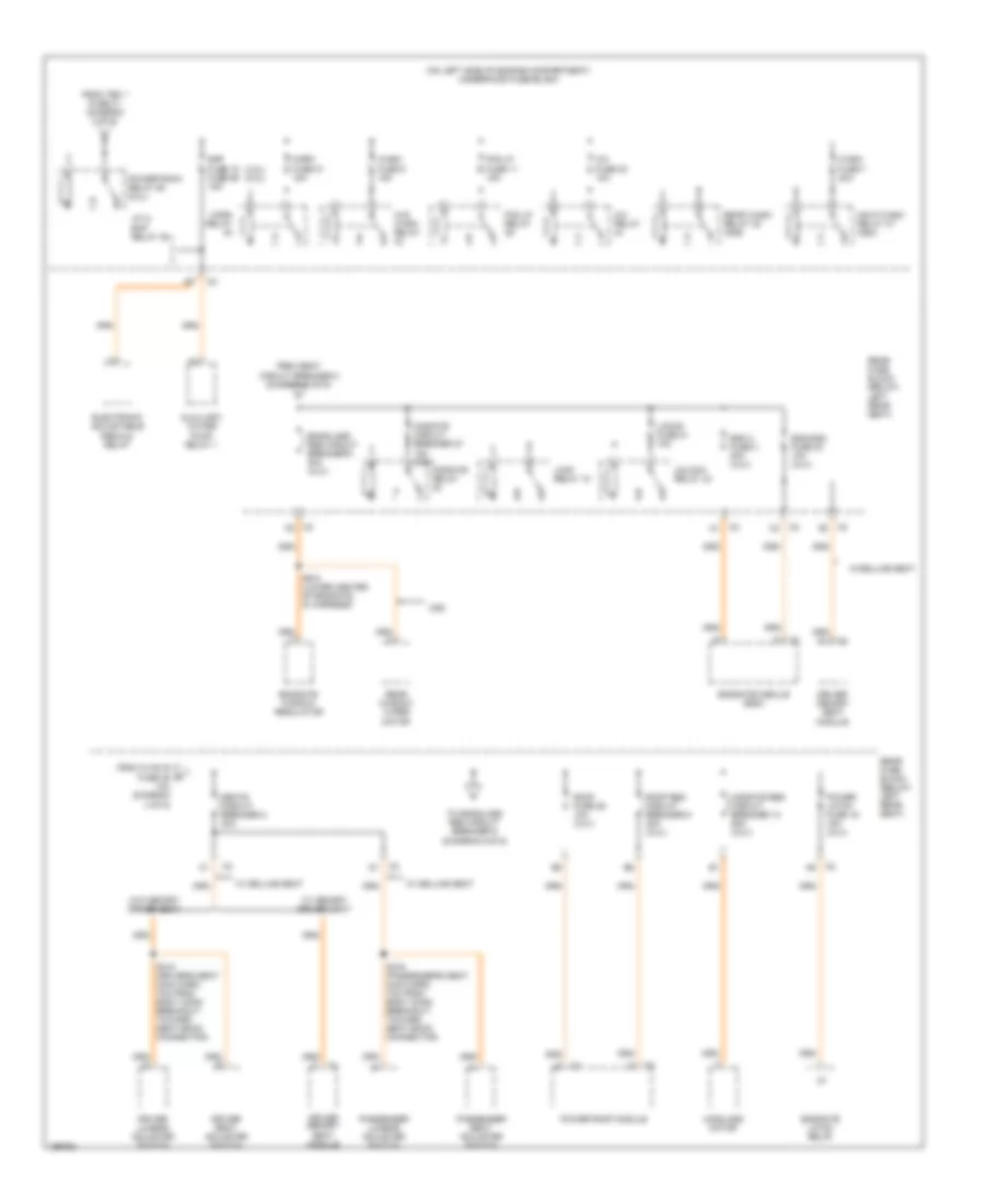 https://portal-diagnostov.com/license.html
Automotive Electricians Portal FZCO
Automotive Electricians Portal FZCO
https://portal-diagnostov.com/license.html
https://portal-diagnostov.com/license.html
Automotive Electricians Portal FZCO
Automotive Electricians Portal FZCOList of elements for Power Distribution Wiring Diagram (6 of 6) for Chevrolet TrailBlazer 2005:
- (4.2l) (5.3l)
- (jf 4) eap relay 49
- (on left side of engine compartment) underhood fuse block
- 10a (diagram 4 of 6)
- A/c fuse 30 10a
- A/c relay
- Auxiliary water pump relay 1
- Cd6
- Driver lumbar adjuster switch
- Driver memory seat module
- Driver seat adjuster switch
- Eap fuse 15 fuse 59 15a
- Egm 2 fuse 3 30a (xuv)
- Egm/dsm fuse 23 10a (xuv)
- Electronic adjustable pedals relay
- Endgate latch relay
- Endgate module (egm)
- Endgate window regulator
- Endglass reg circuit breaker 9 30a (xuv)
- Fog lp fuse 11 15a
- Fog lp relay
- From hvac b fuse 36 p
- From seat circuit breaker 8 (diagram 6 of 6)
- From tbc 1 fuse 31 (diagram 3 of 6)
- Hdlp wash relay 37 (ce4)
- Horn fuse 21 15a
- Horn relay
- Lock relay 18
- Locks fuse 21 10a
- Midgate circuit breaker 27 15a (xuv)
- Midgate reg circuit breaker 13 25a (xuv)
- Midgate relay
- Midglass motor
- Passenger lumbar adjuster switch
- Passenger seat adjuster switch
- Power latch fuse 19 15a (xuv)
- Power roof module
- Powertrain relay 60 (5.3l)
- Rear fuse block (below left rear seat)
- Rear wash relay 38 (cd6)
- Rear window wiper motor
- Roof fuse 25 10a (xuv)
- Roof reg circuit breaker 6 30a (xuv)
- S318 (driver's seat main harn, 7cm from body conn breakout, toward seat back connector)
- S319 (passenger's seat main harn, 7cm from body conn breakout, toward seat back connector)
- S910 (lower center of endgate, in harness)
- Seats circuit breaker 8 30a
- To endglass reg circuit breaker 9 (diagram 6 of 6)
- Unlock relay 24
- W/ deluxe seat
- W/ memory driver seat
- W/deluxe seat
- W/o memory driver seat
- W/s wash relay
- Wash fuse 7 20a
- Wash fuse 9 15a
POWER DOOR LOCKS
Power Door Locks Wiring Diagram for Chevrolet TrailBlazer 2005
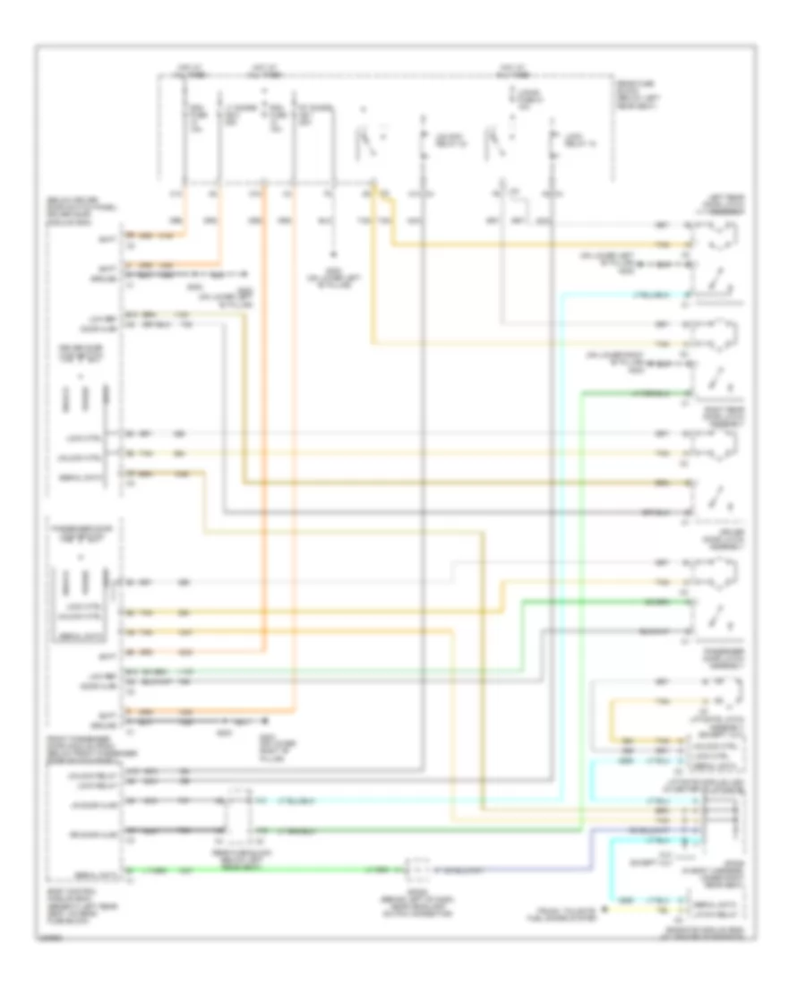 https://portal-diagnostov.com/license.html
Automotive Electricians Portal FZCO
Automotive Electricians Portal FZCO
https://portal-diagnostov.com/license.html
https://portal-diagnostov.com/license.html
Automotive Electricians Portal FZCO
Automotive Electricians Portal FZCOList of elements for Power Door Locks Wiring Diagram for Chevrolet TrailBlazer 2005:
- (below driver door switch panel) driver door module (ddm)
- (on lower left "b" pillar) g302
- (on lower right "b" pillar) g303
- A12
- A13
- B10
- Batt
- Body control module (bcm) (beneath left rear seat, on rear fuse block)
- C10
- C4 a13
- C4 a5
- D10
- Ddm fuse 10a
- Door ajar
- Driver door latch assembly
- Driver door lock switch
- Endgate module (egm) (at center of endgate)
- F10
- Front passenger door module (fpdm) (below front passenger door switch panel)
- G302 (on lower left "b" pillar)
- G303 (on lower right "b" pillar)
- Ground
- Hot at all times
- Latch relay
- Left rear door latch assembly
- Liftgate latch assembly (except xuv)
- Liftgate module (lgm) (in center of liftgate)
- Lock
- Lock ctrl
- Lock relay
- Lock relay 18
- Locks fuse 21 10a
- Low ref
- Lr door ajar
- Lt doors cb 2 25a
- Nca
- Passenger door latch assembly
- Passenger door lock switch
- Pdm fuse 10a
- Power
- Rear fuse block (below left rear seat)
- Right rear door latch assembly
- Rr door ajar
- Rt doors cb 1 25a
- S302
- S303
- Serial data
- Sp205 (behind left of dash, near headlamp switch connector)
- Sp306 (in body harness, under right rear seat)
- Tan
- Trunk, tailgate, fuel doors system
- Unlock
- Unlock ctrl
- Unlock relay
- Unlock relay 24
- Xuv except xuv
POWER MIRRORS
Automatic Day/Night Mirror Wiring Diagram for Chevrolet TrailBlazer 2005
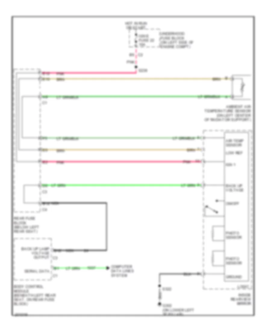 https://portal-diagnostov.com/license.html
Automotive Electricians Portal FZCO
Automotive Electricians Portal FZCO
https://portal-diagnostov.com/license.html
https://portal-diagnostov.com/license.html
Automotive Electricians Portal FZCO
Automotive Electricians Portal FZCOList of elements for Automatic Day/Night Mirror Wiring Diagram for Chevrolet TrailBlazer 2005:
- Air temp sensor
- Ambient air temperature sensor (on left center of radiator support)
- B12
- B6 c2
- Back up lamp voltage output c3
- Back up voltage
- Body control module (beneath left rear seat, on rear fuse block)
- Computer data lines system
- E10
- E12
- G302 (on lower left "b" pillar)
- Ground
- Hot in run or start
- Ign 1
- Ign e fuse 22 10a
- Inside rearview mirror
- Logic
- Low ref
- Nca
- On/off
- Photo sensor
- Pnk
- Rear fuse block (below left rear seat)
- S239
- S322
- Serial data
- Underhood fuse block (on left side of engine compt)
Power Mirrors Wiring Diagram for Chevrolet TrailBlazer 2005
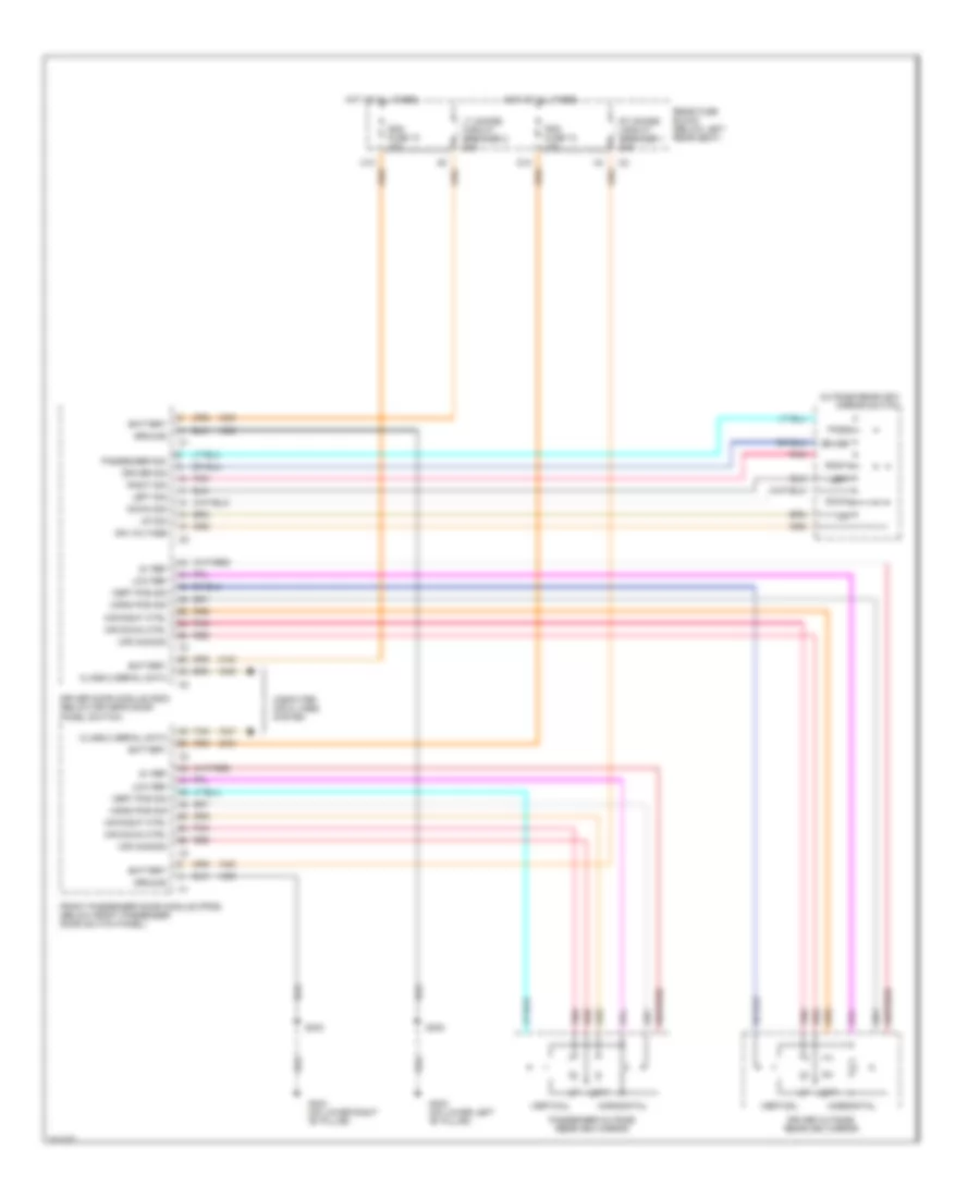 https://portal-diagnostov.com/license.html
Automotive Electricians Portal FZCO
Automotive Electricians Portal FZCO
https://portal-diagnostov.com/license.html
https://portal-diagnostov.com/license.html
Automotive Electricians Portal FZCO
Automotive Electricians Portal FZCOList of elements for Power Mirrors Wiring Diagram for Chevrolet TrailBlazer 2005:
- 5v ref
- Battery
- C10
- Class 2 serial data
- Computer data lines system
- D10
- Ddm fuse 10 10a
- Down
- Down sig
- Driver
- Driver door module (ddm) (below driver's door panel switch)
- Driver outside rearview mirror
- Driver sig
- Front passenger door module (fpdm) (below front passenger door switch panel)
- G302 (on lower left "b" pillar)
- G303 (on lower right "b" pillar)
- Ground
- Horiz pos sig
- Horizontal
- Hot at all times
- Ign voltage
- Left
- Left sig
- Low ref
- Lt doors circuit breaker 2 25a
- Mir common
- Mir down ctrl
- Mir right ctrl
- Outside rearview mirror switch
- Pass
- Passenger outside rearview mirror
- Passenger sig
- Pdm fuse 12 10a
- Pnk
- Rear fuse block (below left rear seat)
- Red
- Right
- Right sig
- Rt doors circuit breaker 1 25a
- S302
- S303
- Tan
- Up sig
- Vert pos sig
- Vertical
POWER SEATS
8-Way Adjustable Power Seat Wiring Diagram for Chevrolet TrailBlazer 2005
 https://portal-diagnostov.com/license.html
Automotive Electricians Portal FZCO
Automotive Electricians Portal FZCO
https://portal-diagnostov.com/license.html
https://portal-diagnostov.com/license.html
Automotive Electricians Portal FZCO
Automotive Electricians Portal FZCOList of elements for 8-Way Adjustable Power Seat Wiring Diagram for Chevrolet TrailBlazer 2005:
- Driver seat adjuster switch
- Driver seat front vertical motor
- Driver seat horizontal motor
- Driver seat rear vertical motor
- Driver seat recline motor
- Front passenger seat adjuster switch
- Fwd
- G302 (on lower left "b" pillar)
- G303 (on lower right "b" pillar)
- Hot at all times
- Passenger seat front vertical motor
- Passenger seat horizontal motor
- Passenger seat rear vertical motor
- Passenger seat recline motor
- Rear fuse block (below left rear seat)
- Rwd
- S311
- S317
- S318
- S319
- Seats circuit breaker 30a
- Tan
Driver Heated Seat Wiring Diagram for Chevrolet TrailBlazer 2005
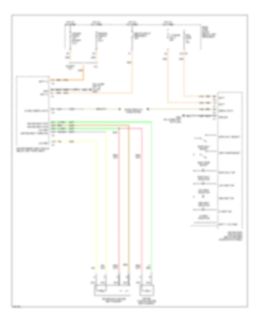 https://portal-diagnostov.com/license.html
Automotive Electricians Portal FZCO
Automotive Electricians Portal FZCO
https://portal-diagnostov.com/license.html
https://portal-diagnostov.com/license.html
Automotive Electricians Portal FZCO
Automotive Electricians Portal FZCOList of elements for Driver Heated Seat Wiring Diagram for Chevrolet TrailBlazer 2005:
- (on lower left "b" pillar) g302
- A11
- A12
- B10
- B11
- B12
- Back only ind
- Back only indicator
- Back only select
- Bat (+)
- Batt
- Batt (+)
- Batt + voltage
- C2 c10
- Class 2 serial data
- Computer data lines system
- Ddm fuse 10a
- Driver back heated seat element
- Driver cushion heated seat element
- Driver door module (ddm) (below driver's door switch panel)
- Driver memory seat module (below left front seat)
- Egm/dsm fuse 23 10a (xuv)
- Except xuv
- G302 (on lower left "b" pillar)
- Gnd
- Ground
- Heat mode select
- Heated seat pwr
- Heated seat therm sig
- Hi heat ind
- Hi heat indicator
- Hot at all times
- Lgm/dsm fuse 6 10a (except xuv)
- Low heat ind
- Low heat indicator
- Low ref
- Lt doors c.b. 2 25a
- Med heat ind
- Med heat indicator
- Nca
- Rear fuse block (below left rear seat)
- S311
- S327
- Seats circuit breaker 8 30a
- Serial data
- Xuv
Lumbar Wiring Diagram for Chevrolet TrailBlazer 2005
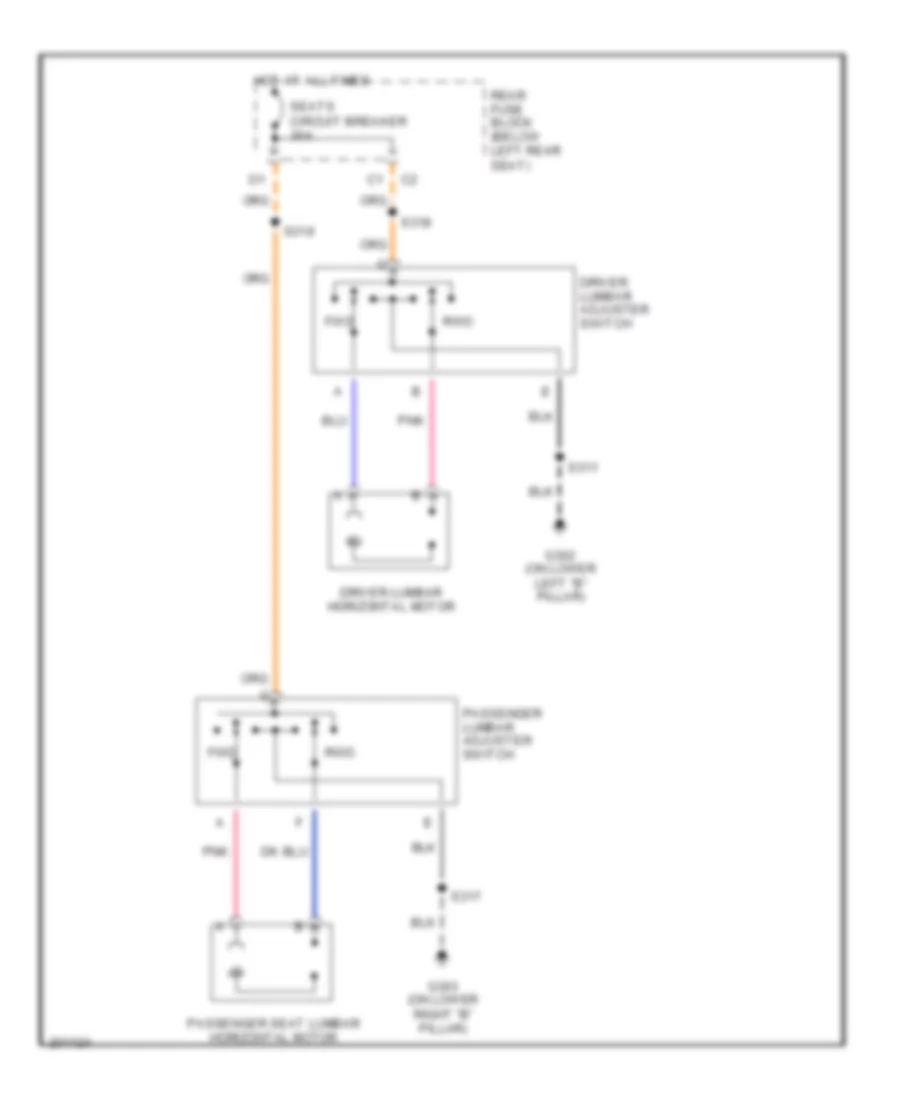 https://portal-diagnostov.com/license.html
Automotive Electricians Portal FZCO
Automotive Electricians Portal FZCO
https://portal-diagnostov.com/license.html
https://portal-diagnostov.com/license.html
Automotive Electricians Portal FZCO
Automotive Electricians Portal FZCOList of elements for Lumbar Wiring Diagram for Chevrolet TrailBlazer 2005:
- Driver lumbar adjuster switch
- Driver lumbar horizontal motor
- Fwd
- G302 (on lower left "b" pillar)
- G303 (on lower right "b" pillar)
- Hot at all times
- Passenger lumbar adjuster switch
- Passenger seat lumbar horizontal motor
- Pnk
- Rear fuse block (below left rear seat)
- Rwd
- S311
- S317
- S318
- S319
- Seats circuit breaker 30a
Passenger"s Heated Seat Wiring Diagram for Chevrolet TrailBlazer 2005
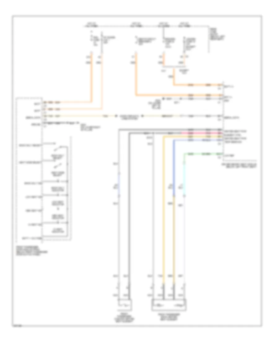 https://portal-diagnostov.com/license.html
Automotive Electricians Portal FZCO
Automotive Electricians Portal FZCO
https://portal-diagnostov.com/license.html
https://portal-diagnostov.com/license.html
Automotive Electricians Portal FZCO
Automotive Electricians Portal FZCOList of elements for Passenger"s Heated Seat Wiring Diagram for Chevrolet TrailBlazer 2005:
- A10
- B12
- Back only ind
- Back only indicator
- Back only select
- Bat (+)
- Batt
- Batt (+)
- Batt + voltage
- C2 a5
- Computer data lines system
- D10
- Driver memory seat module (below left front seat)
- Egm/dsm fuse 23 10a (xuv)
- Element ctrl
- Except xuv
- Front passenger back heated seat element
- Front passenger cushion heated seat element
- Front passenger door module (fpdm) (below front passenger door switch panel)
- G302 (on lower left "b" pillar)
- G303 (on lower right "b" pillar)
- Gnd
- Ground
- Heat mode select
- Heated seat pwr
- Hi heat ind
- Hi heat indicator
- Hot at all times
- Lgm/dsm fuse 19 10a (except xuv)
- Low heat ind
- Low heat indicator
- Low ref
- Med heat ind
- Med heat indicator
- Nca
- Pdm fuse 10a
- Pnk
- Rear fuse block (below left rear seat)
- Rt doors c.b. 1 25a
- S311
- S316
- Seats circuit breaker 8 30a
- Serial data
- Tan
- Temp sens sig
- Xuv
POWER TOP/SUNROOF
Power Top/Sunroof Wiring Diagram for Chevrolet TrailBlazer 2005
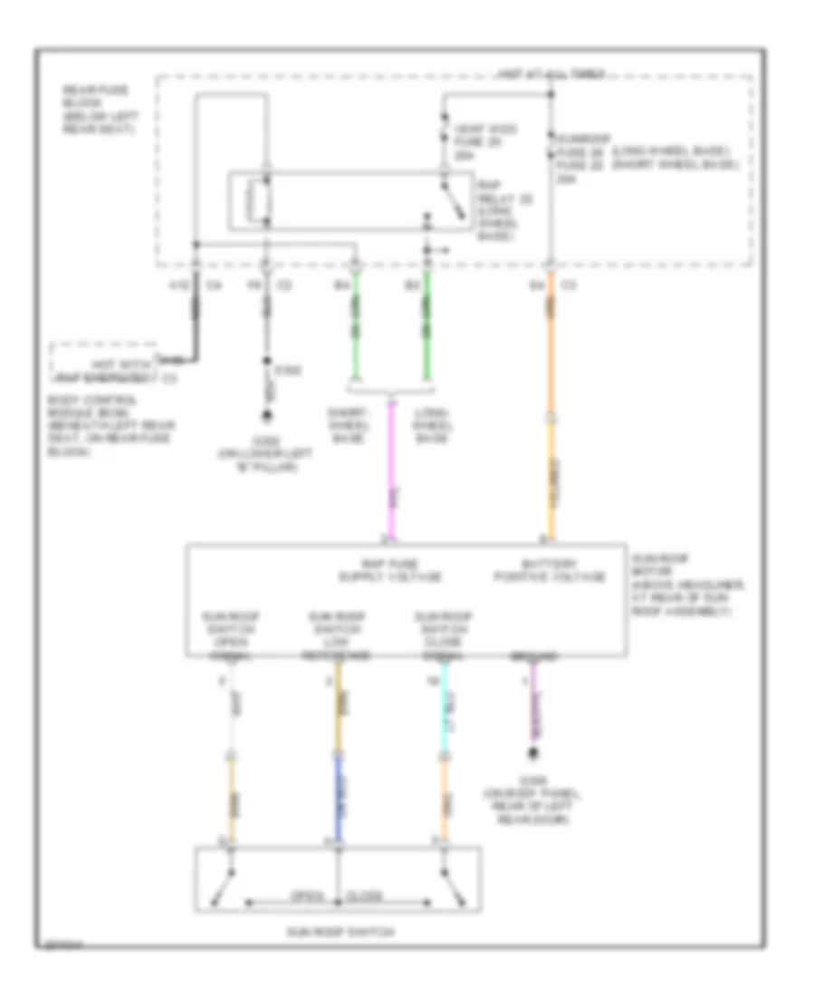 https://portal-diagnostov.com/license.html
Automotive Electricians Portal FZCO
Automotive Electricians Portal FZCO
https://portal-diagnostov.com/license.html
https://portal-diagnostov.com/license.html
Automotive Electricians Portal FZCO
Automotive Electricians Portal FZCOList of elements for Power Top/Sunroof Wiring Diagram for Chevrolet TrailBlazer 2005:
- (long wheel base) (short wheel base)
- A12
- Battery positive voltage
- Body control module (bcm) (beneath left rear seat, on rear fuse block)
- Close
- G302 (on lower left "b" pillar)
- G306 (on body panel, rear of left rear door)
- Ground
- Hot at all times
- Hot with rap energized c3
- Long- wheel base
- Nca
- Open
- Rap relay 22 (long wheel base)
- Rear fuse block (below left rear seat)
- S302
- Short- wheel base
- Sun roof motor (above headliner, at rear of sun roof assembly)
- Sun roof switch
- Sun roof switch close signal
- Sun roof switch low reference
- Sun roof switch open signal
- Sunroof fuse 28 fuse 20 20a
- Vent wdo fuse 20 20a
POWER WINDOWS
Power Windows Wiring Diagram for Chevrolet TrailBlazer 2005
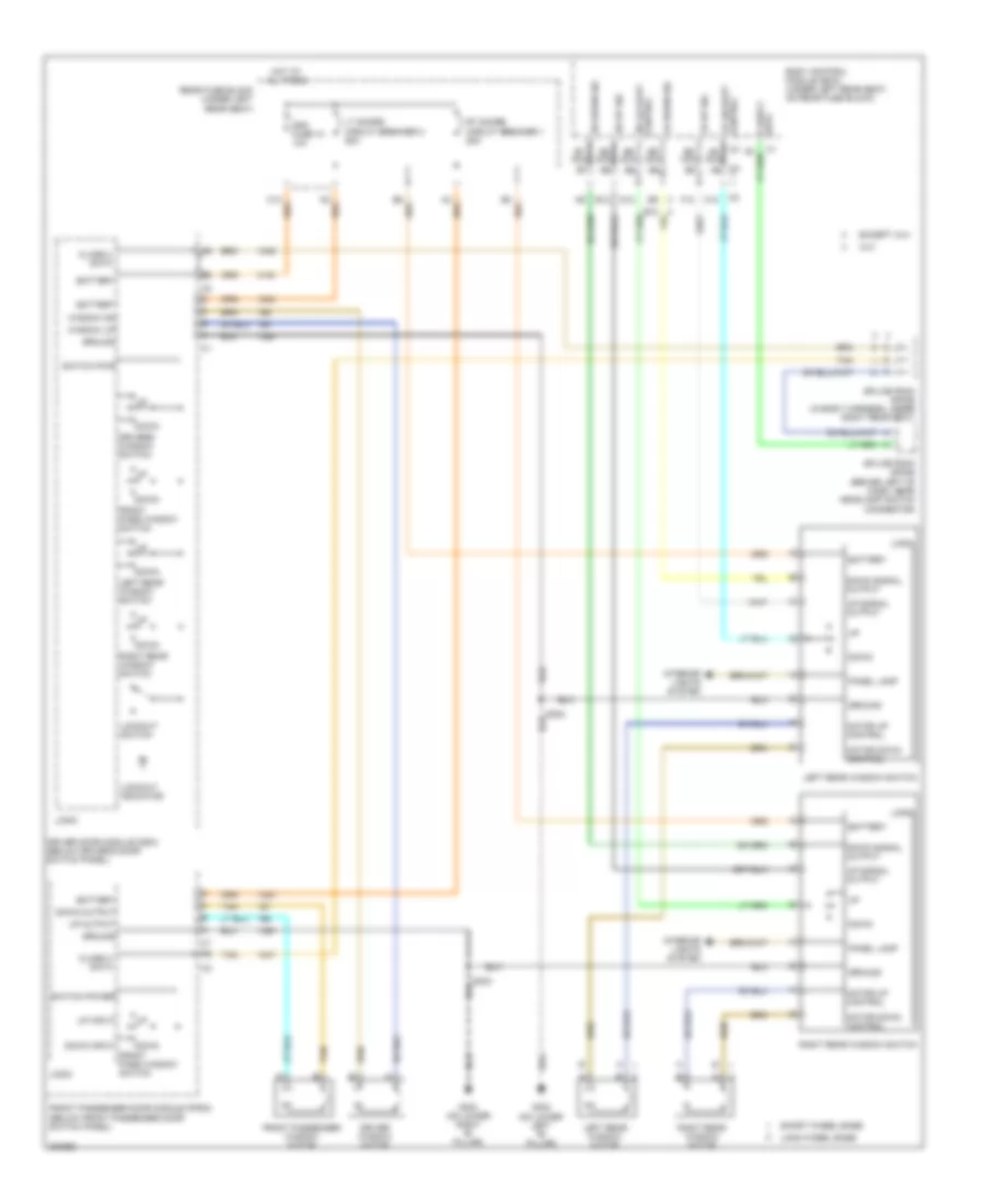 https://portal-diagnostov.com/license.html
Automotive Electricians Portal FZCO
Automotive Electricians Portal FZCO
https://portal-diagnostov.com/license.html
https://portal-diagnostov.com/license.html
Automotive Electricians Portal FZCO
Automotive Electricians Portal FZCOList of elements for Power Windows Wiring Diagram for Chevrolet TrailBlazer 2005:
- (on lower left "b" pillar)
- A6 nca
- B5 nca
- B6 nca
- B7 nca
- B8 nca
- B9 nca
- Battery
- Body control module (bcm) (under left rear seat, on rear fuse block)
- C12
- Class 2 data
- D12
- Ddm fuse 10 10a
- Down
- Down input
- Down output
- Down signal output
- Driver door module (ddm) (below driver's door switch panel)
- Driver window motor
- Drivers window switch
- E12
- Except xuv
- F12
- Front pass window switch
- Front passenger door module (fpdm) (below front passenger door switch panel)
- Front passenger window motor
- G302
- G303 (on lower right "b" pillar)
- Ground
- Hot at all times
- Interior lights system
- Left rear window motor
- Left rear window switch
- Lockout indicator
- Lockout switch
- Logic
- Long wheel base
- Lr down sig
- Lr lockout control
- Lr up sig
- Lt doors circuit breaker 2 25a
- Motor down control
- Motor up control
- Panel lamp
- Rear fuse block (under left rear seat)
- Right rear window motor
- Right rear window switch
- Rr down sig
- Rr lockout control
- Rr up sig
- Rt doors circuit breaker 1 25a
- Short wheel base
- Splice pack sp205 (behind left of dash, near headlamp switch connector)
- Splice pack sp306 (in body harness, under right rear seat)
- Switch power
- Switch pwr
- Tan
- Up input
- Up output
- Up signal output
- Window dn
- Window up
- Xuv
Rear Quarter Windows Wiring Diagram, Long Wheel Base for Chevrolet TrailBlazer 2005
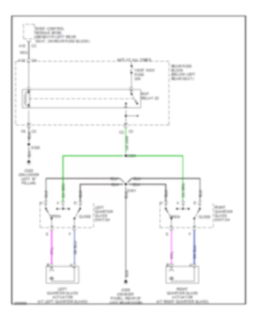 https://portal-diagnostov.com/license.html
Automotive Electricians Portal FZCO
Automotive Electricians Portal FZCO
https://portal-diagnostov.com/license.html
https://portal-diagnostov.com/license.html
Automotive Electricians Portal FZCO
Automotive Electricians Portal FZCOList of elements for Rear Quarter Windows Wiring Diagram, Long Wheel Base for Chevrolet TrailBlazer 2005:
- A12
- Body control module (bcm) (beneath left rear seat, on rear fuse block)
- Close
- G302 (on lower left "b" pillar)
- G306 (on body panel, rear of left rear door)
- Hot at all times
- Left quarter glass actuator (at left quarter glass)
- Left quarter glass switch
- Nca
- Open
- Rap relay 22
- Rear fuse block (below left rear seat)
- Right quarter glass actuator (at right quarter glass)
- Right quarter glass switch
- S301
- S302
- Vent wdo fuse 20a
RADIO
Base Radio Wiring Diagram, with Rear Seat Audio (1 of 2) for Chevrolet TrailBlazer 2005
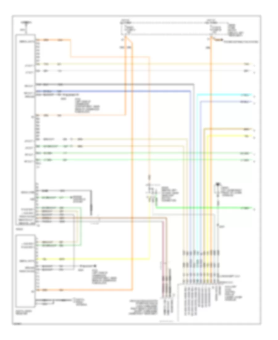 https://portal-diagnostov.com/license.html
Automotive Electricians Portal FZCO
Automotive Electricians Portal FZCO
https://portal-diagnostov.com/license.html
https://portal-diagnostov.com/license.html
Automotive Electricians Portal FZCO
Automotive Electricians Portal FZCOList of elements for Base Radio Wiring Diagram, with Rear Seat Audio (1 of 2) for Chevrolet TrailBlazer 2005:
- A10
- A11
- A12
- A16
- A4 (swb & xuv)
- Antenna
- Auxiliary hvac control module (under lower console)
- B10
- B11
- B12
- B16 (lwb except xuv)
- B6 b6
- Bare
- Digital radio antenna
- Digital radio receiver
- Drain wire
- Engine controls system
- G102 (left side of underhood compartment, near rear of underhood fuse block)
- G201
- Ground
- Hot at all times
- Hvac b fuse 36 10a
- L aud sig +
- Lf out +
- Lf out -
- Lr low level audio sig +
- Lr low level audio sig -
- Lr out +
- Lr out -
- Lr speaker out +
- Lr speaker out -
- Nca
- Power distribution system
- R aud sig +
- Radio
- Radio fuse 41 15a
- Radio on sig
- Rear fuse block (below left rear seat)
- Remote l sig
- Remote out -
- Rf out +
- Rf out -
- Rr low level audio sig +
- Rr low level audio sig -
- Rr out +
- Rr out -
- Rr speaker out +
- Rr speaker out -
- S202
- S307
- Serial data
- Sp201 (at lower right front of lower console)
- Sp205 (behind left of dash, near headlamp switch connector)
- Tan
- Vehicle communication interface module (long wheelbase: right rear floor pan) (short wheelbase: under right rear seat)
- Vss
Base Radio Wiring Diagram, with Rear Seat Audio (2 of 2) for Chevrolet TrailBlazer 2005
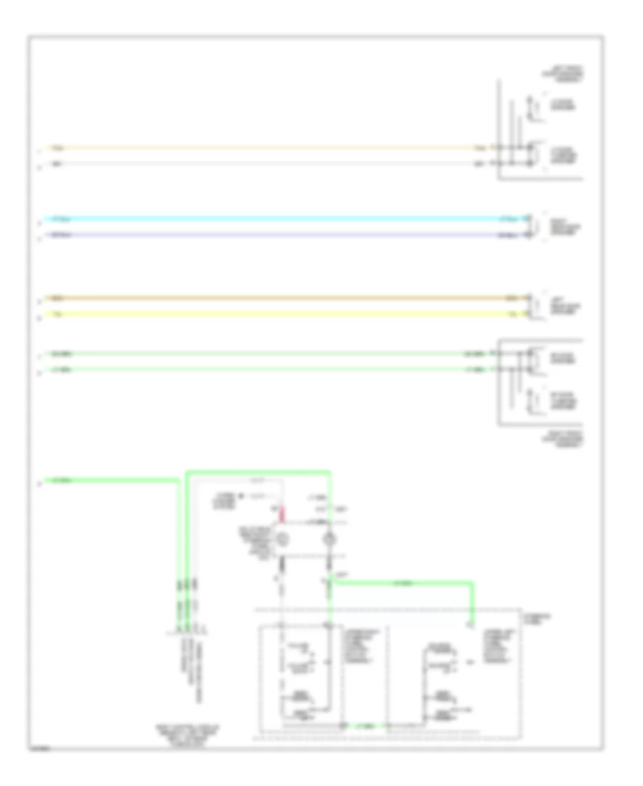 https://portal-diagnostov.com/license.html
Automotive Electricians Portal FZCO
Automotive Electricians Portal FZCO
https://portal-diagnostov.com/license.html
https://portal-diagnostov.com/license.html
Automotive Electricians Portal FZCO
Automotive Electricians Portal FZCOList of elements for Base Radio Wiring Diagram, with Rear Seat Audio (2 of 2) for Chevrolet TrailBlazer 2005:
- A12
- Body control module (beneath left rear seat, on rear fuse block)
- C201
- C277
- Inflatable restraint steering wheel module coil
- Left front door speaker assembly
- Left rear door speaker
- Lf door speaker
- Lf door tweeter speaker
- Nca
- Pnk
- Radio control signal
- Rf door speaker
- Rf door tweeter speaker
- Right front door speaker assembly
- Right rear door speaker
- Seek down
- Seek prog
- Seek up
- Seek voice
- Serial data
- Source down
- Source up
- Steering wheel
- Tan
- Upper left steering wheel control switch assembly
- Upper right steering wheel control switch assembly
- Volume down
- Volume up
- Wiper/ washer system
Base Radio Wiring Diagram, without Rear Seat Audio for Chevrolet TrailBlazer 2005
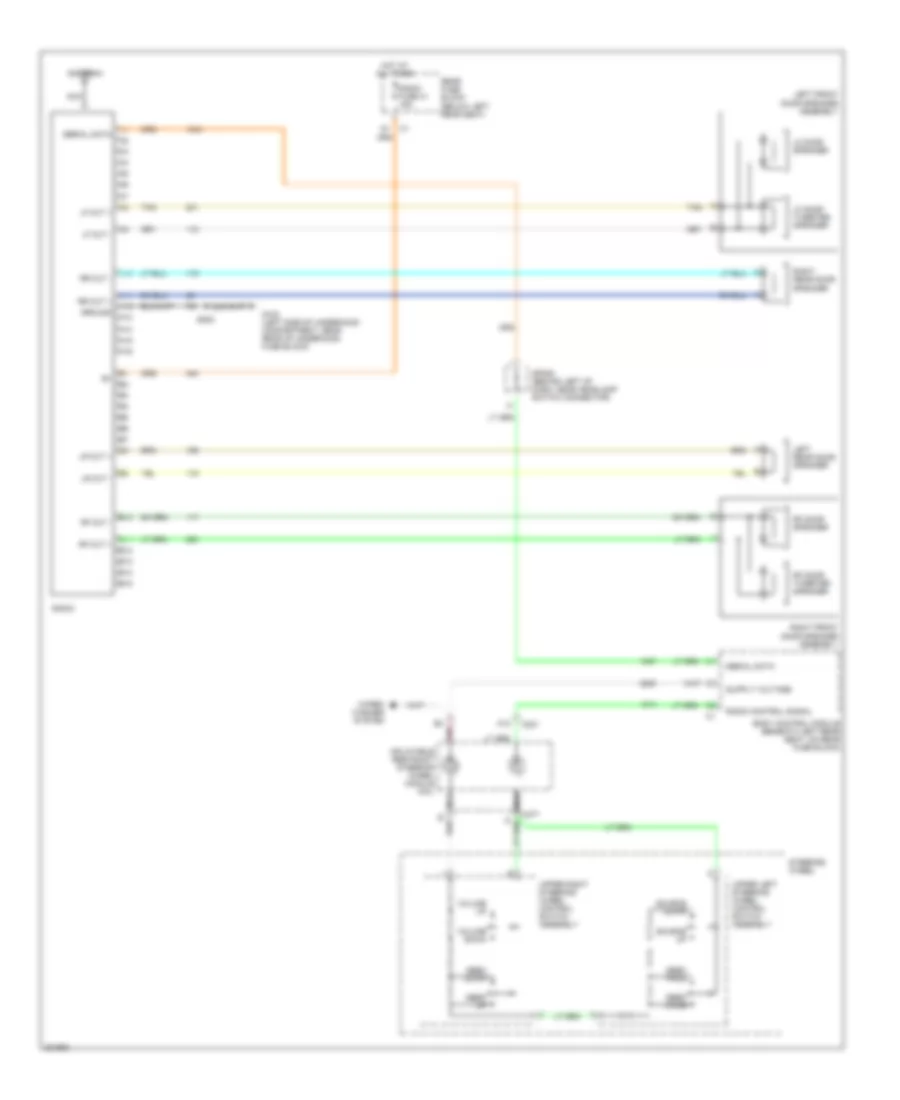 https://portal-diagnostov.com/license.html
Automotive Electricians Portal FZCO
Automotive Electricians Portal FZCO
https://portal-diagnostov.com/license.html
https://portal-diagnostov.com/license.html
Automotive Electricians Portal FZCO
Automotive Electricians Portal FZCOList of elements for Base Radio Wiring Diagram, without Rear Seat Audio for Chevrolet TrailBlazer 2005:
- A10
- A11
- A12
- A13
- A14
- A15
- A16
- Antenna
- B10
- B11
- B12
- B13
- B14
- B15
- Body control module (beneath left rear seat, on rear fuse block)
- C201
- C277
- G102 (left side of underhood compartment, near rear of underhood fuse block)
- Ground
- Hot at all times
- Inflatable restraint steering wheel module coil
- Left front door speaker assembly
- Left rear door speaker
- Lf door speaker
- Lf door tweeter speaker
- Lf out +
- Lf out -
- Lr out +
- Lr out -
- Nca
- Pnk
- Radio
- Radio control signal
- Radio fuse 41 15a
- Rear fuse block (below left rear seat)
- Rf door speaker
- Rf door tweeter speaker
- Rf out +
- Rf out -
- Right front door speaker assembly
- Right rear door speaker
- Rr out +
- Rr out -
- S202
- Seek down
- Seek prog
- Seek up
- Seek voice
- Serial data
- Source down
- Source up
- Sp205 (behind left of dash, near headlamp switch connector)
- Steering wheel
- Tan
- Upper left steering wheel control switch assembly
- Upper right steering wheel control switch assembly
- Volume down
- Volume up
- Wiper/ washer system
DVD Player Wiring Diagram for Chevrolet TrailBlazer 2005
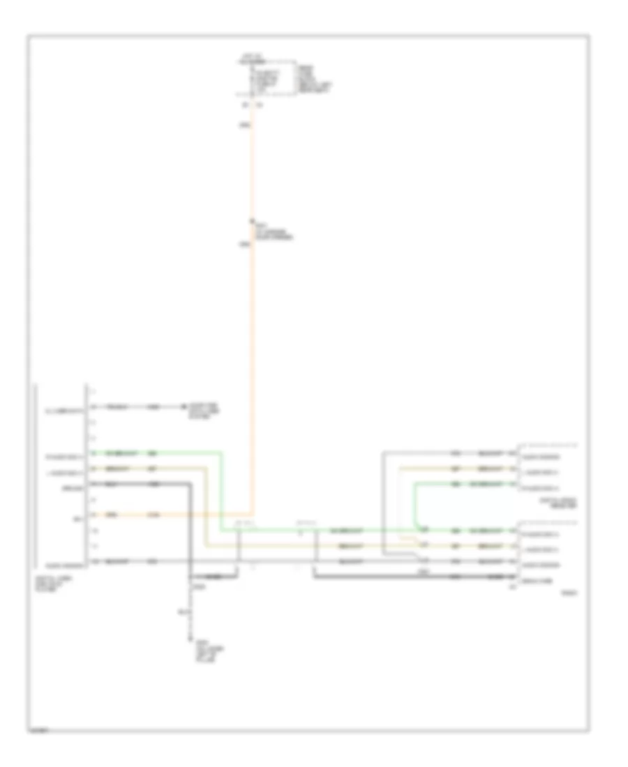 https://portal-diagnostov.com/license.html
Automotive Electricians Portal FZCO
Automotive Electricians Portal FZCO
https://portal-diagnostov.com/license.html
https://portal-diagnostov.com/license.html
Automotive Electricians Portal FZCO
Automotive Electricians Portal FZCOList of elements for DVD Player Wiring Diagram for Chevrolet TrailBlazer 2005:
- Audio common
- B(+)
- Bare
- C221
- Cl 2 ser data
- Computer data lines system
- Digital radio receiver
- Digital video disk (dvd) player
- Drain wire
- G302 (on lower left "b" pillar)
- Ground
- Hot at all times
- L audio sig (+)
- Oh batt/ onstar fuse 27 10a
- R audio sig (+)
- Radio
- Rear fuse block (below left rear seat)
- S322
- S341 (w/ garage door opener)
Premium Sound Radio Wiring Diagram, with Rear Seat Audio (1 of 2) for Chevrolet TrailBlazer 2005
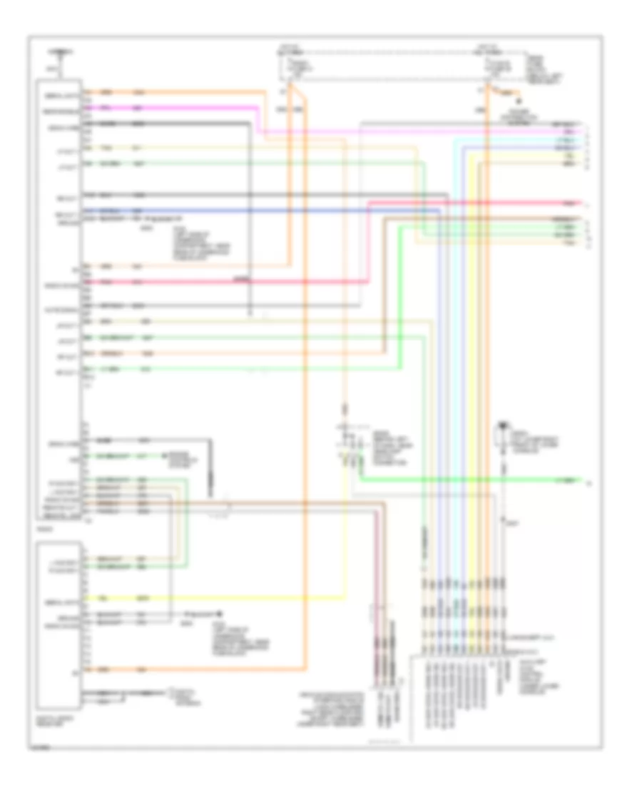 https://portal-diagnostov.com/license.html
Automotive Electricians Portal FZCO
Automotive Electricians Portal FZCO
https://portal-diagnostov.com/license.html
https://portal-diagnostov.com/license.html
Automotive Electricians Portal FZCO
Automotive Electricians Portal FZCOList of elements for Premium Sound Radio Wiring Diagram, with Rear Seat Audio (1 of 2) for Chevrolet TrailBlazer 2005:
- A10
- A11
- A12
- A16
- A4 (swb & xuv)
- Antenna
- Auxiliary hvac control module (under lower console)
- B10
- B11
- B12
- B16 (lwb except xuv)
- B6 b6
- Bare
- Digital radio antenna
- Digital radio receiver
- Drain wire
- Engine controls system
- G102 (left side of underhood compartment, near rear of underhood fuse block)
- G201
- Ground
- Hot at all times
- Hvac b fuse 36 10a
- L aud sig +
- Lf out +
- Lf out -
- Lr low level audio sig +
- Lr low level audio sig -
- Lr out +
- Lr out -
- Lr speaker out +
- Lr speaker out -
- Mute signal
- Nca
- Pnk
- Power distribution system
- R aud sig +
- Radio
- Radio fuse 41 15a
- Radio on sig
- Rear enable
- Rear fuse block (below left rear seat)
- Remote l sig
- Remote out -
- Rf out +
- Rf out -
- Rr low level audio sig +
- Rr low level audio sig -
- Rr out +
- Rr out -
- Rr speaker out +
- Rr speaker out -
- S202
- S307
- Serial data
- Sp201 (at lower right front of lower console)
- Sp205 (behind left of dash, near headlamp switch connector)
- Tan
- Vehicle communication interface module (long wheelbase: right rear floor pan) (short wheelbase: under right rear seat)
- Vss
Premium Sound Radio Wiring Diagram, with Rear Seat Audio (2 of 2) for Chevrolet TrailBlazer 2005
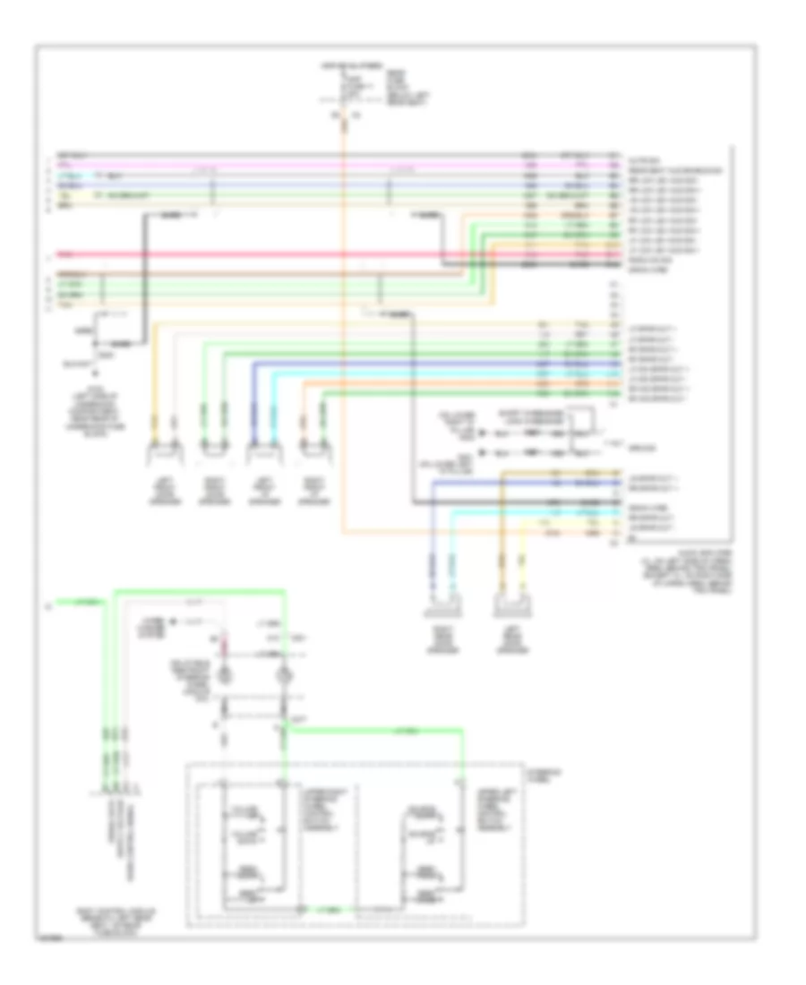 https://portal-diagnostov.com/license.html
Automotive Electricians Portal FZCO
Automotive Electricians Portal FZCO
https://portal-diagnostov.com/license.html
https://portal-diagnostov.com/license.html
Automotive Electricians Portal FZCO
Automotive Electricians Portal FZCOList of elements for Premium Sound Radio Wiring Diagram, with Rear Seat Audio (2 of 2) for Chevrolet TrailBlazer 2005:
- (on lower right "d" pillar) g402
- A a
- A10
- A11
- A12
- Amp fuse 11 20a
- Audio amplifier (xl: on left side of cargo area, behind trim panel) (except xl: on right side of cargo area, behind trim panel)
- B10
- B11
- B12
- Bare
- Body control module (beneath left rear seat, on rear fuse block)
- C201
- C277
- Drain wire
- G102 (left side of underhood compartment, near rear of underhood fuse block)
- G401 (on lower left "d" pillar)
- Ground
- Hot at all times
- Inflatable restraint steering wheel module coil
- Left front door speaker
- Left front i/p speaker
- Left rear door speaker
- Lf low lev aud sig +
- Lf low lev aud sig -
- Lf mid spkr out +
- Lf mid spkr out -
- Lf spkr out +
- Lf spkr out -
- Long wheelbase
- Lr low lev aud sig +
- Lr low lev aud sig -
- Lr spkr out +
- Lr spkr out -
- Mute sig
- Nca
- Pnk
- Radio control signal
- Radio on sig
- Rear fuse block (below left rear seat)
- Rear seat aud enable sig
- Rf low lev aud sig +
- Rf low lev aud sig -
- Rf mid spkr out +
- Rf mid spkr out -
- Rf spkr out +
- Rf spkr out -
- Right front door speaker
- Right front i/p speaker
- Right rear door speaker
- Rr low lev aud sig +
- Rr low lev aud sig -
- Rr spkr out +
- Rr spkr out -
- S202
- S401
- S402
- Seek down
- Seek prog
- Seek up
- Seek voice
- Serial data
- Short wheelbase
- Source down
- Source up
- Steering wheel
- Tan
- Upper left steering wheel control switch assembly
- Upper right steering wheel control switch assembly
- Volume down
- Volume up
- Wiper/ washer system
Premium Sound Radio Wiring Diagram, without Rear Seat Audio (1 of 2) for Chevrolet TrailBlazer 2005
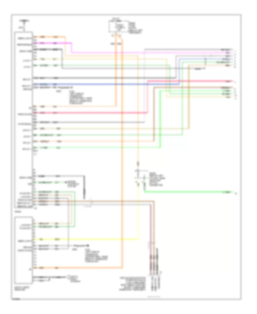 https://portal-diagnostov.com/license.html
Automotive Electricians Portal FZCO
Automotive Electricians Portal FZCO
https://portal-diagnostov.com/license.html
https://portal-diagnostov.com/license.html
Automotive Electricians Portal FZCO
Automotive Electricians Portal FZCOList of elements for Premium Sound Radio Wiring Diagram, without Rear Seat Audio (1 of 2) for Chevrolet TrailBlazer 2005:
- A10
- A11
- A12
- Antenna
- B10
- B11
- B12
- Bare
- Digital radio antenna
- Digital radio receiver
- Drain wire
- Engine controls system
- G102 (left side of underhood compartment, near rear of underhood fuse block)
- Ground
- Hot at all times
- L aud sig +
- Lf out +
- Lf out -
- Lr out +
- Lr out -
- Mute signal
- Nca
- Pnk
- R aud sig +
- Radio
- Radio fuse 41 15a
- Radio on sig
- Rear enable
- Rear fuse block (below left rear seat)
- Remote l sig
- Remote out -
- Rf out +
- Rf out -
- Rr out +
- Rr out -
- S202
- Serial data
- Sp205 (behind left of dash, near headlamp switch connector)
- Tan
- Vehicle communication interface module (long wheelbase: right rear floor pan) (short wheelbase: under right rear seat)
- Vss
Premium Sound Radio Wiring Diagram, without Rear Seat Audio (2 of 2) for Chevrolet TrailBlazer 2005
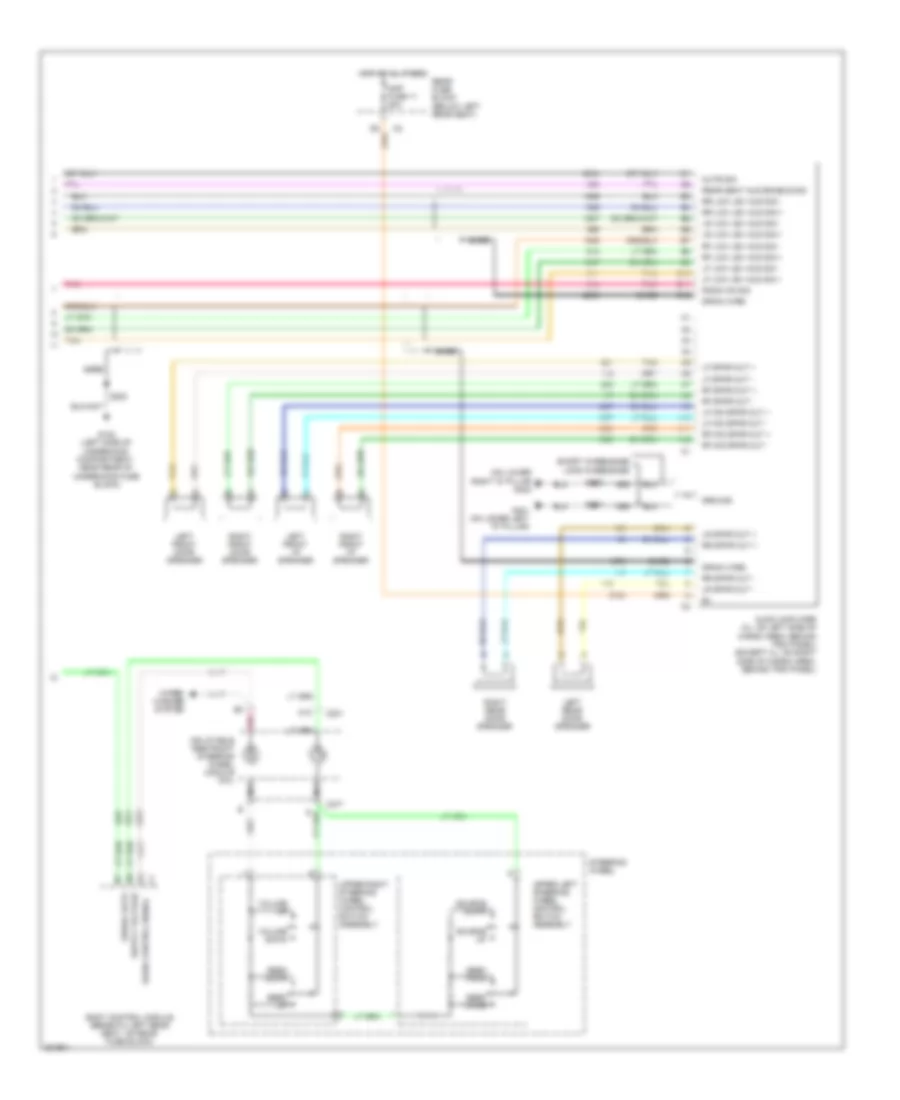 https://portal-diagnostov.com/license.html
Automotive Electricians Portal FZCO
Automotive Electricians Portal FZCO
https://portal-diagnostov.com/license.html
https://portal-diagnostov.com/license.html
Automotive Electricians Portal FZCO
Automotive Electricians Portal FZCOList of elements for Premium Sound Radio Wiring Diagram, without Rear Seat Audio (2 of 2) for Chevrolet TrailBlazer 2005:
- (on lower right "d" pillar g402
- A a
- A10
- A11
- A12
- Amp fuse 11 20a
- Audio amplifier (xl: on left side of cargo area, behind trim panel) (except xl: on right side of cargo area, behind trim panel)
- B10
- B11
- B12
- Bare
- Body control module (beneath left rear seat, on rear fuse block)
- C201
- C277
- Drain wire
- G102 (left side of underhood compartment, near rear of underhood fuse block)
- G401 (on lower left "d" pillar)
- Ground
- Hot at all times
- Inflatable restraint steering wheel module coil
- Left front door speaker
- Left front i/p speaker
- Left rear door speaker
- Lf low lev aud sig +
- Lf low lev aud sig -
- Lf mid spkr out +
- Lf mid spkr out -
- Lf spkr out +
- Lf spkr out -
- Long wheelbase
- Lr low lev aud sig +
- Lr low lev aud sig -
- Lr spkr out +
- Lr spkr out -
- Mute sig
- Nca
- Pnk
- Radio control signal
- Radio on sig
- Rear fuse block (below left rear seat)
- Rear seat aud enable sig
- Rf low lev aud sig +
- Rf low lev aud sig -
- Rf mid spkr out +
- Rf mid spkr out -
- Rf spkr out +
- Rf spkr out -
- Right front door speaker
- Right front i/p speaker
- Right rear door speaker
- Rr low lev aud sig +
- Rr low lev aud sig -
- Rr spkr out +
- Rr spkr out -
- S202
- S401
- S402
- Seek down
- Seek prog
- Seek up
- Seek voice
- Serial data
- Short wheelbase
- Source down
- Source up
- Steering wheel
- Tan
- Upper left steering wheel control switch assembly
- Upper right steering wheel control switch assembly
- Volume down
- Volume up
- Wiper/ washer system
SHIFT INTERLOCK
Ignition Lock Solenoid Wiring Diagram for Chevrolet TrailBlazer 2005
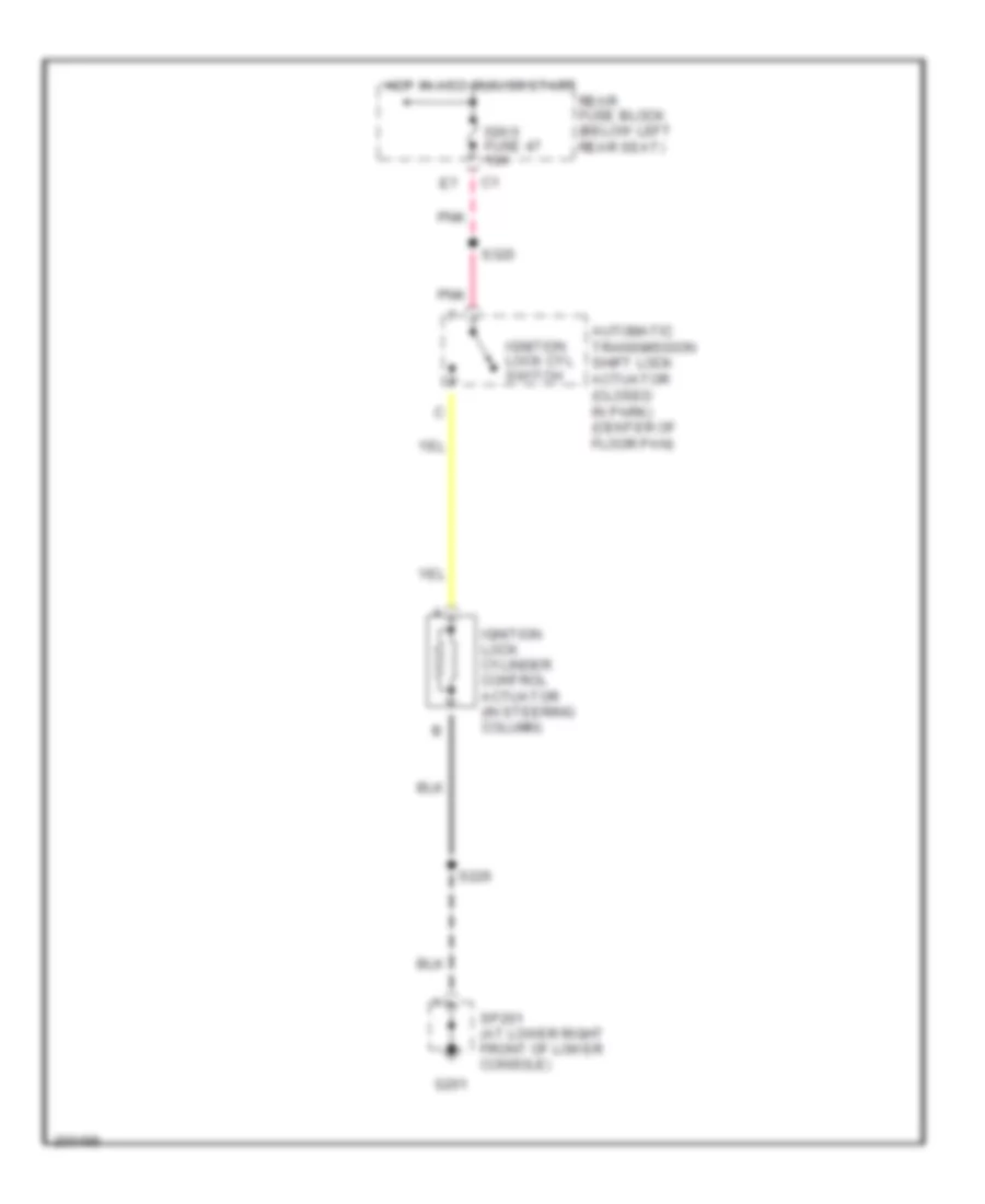 https://portal-diagnostov.com/license.html
Automotive Electricians Portal FZCO
Automotive Electricians Portal FZCO
https://portal-diagnostov.com/license.html
https://portal-diagnostov.com/license.html
Automotive Electricians Portal FZCO
Automotive Electricians Portal FZCOList of elements for Ignition Lock Solenoid Wiring Diagram for Chevrolet TrailBlazer 2005:
- Automatic transmission shift lock actuator (closed in park) (center of floor pan)
- G201
- Hot in acc, run or start
- Ign 0 fuse 47 10a
- Ignition lock cyl switch
- Ignition lock cylinder control actuator (in steering column)
- Pnk
- Rear fuse block (below left rear seat)
- S226
- S320
- Sp201 (at lower right front of lower console)
Shift Interlock Wiring Diagram for Chevrolet TrailBlazer 2005
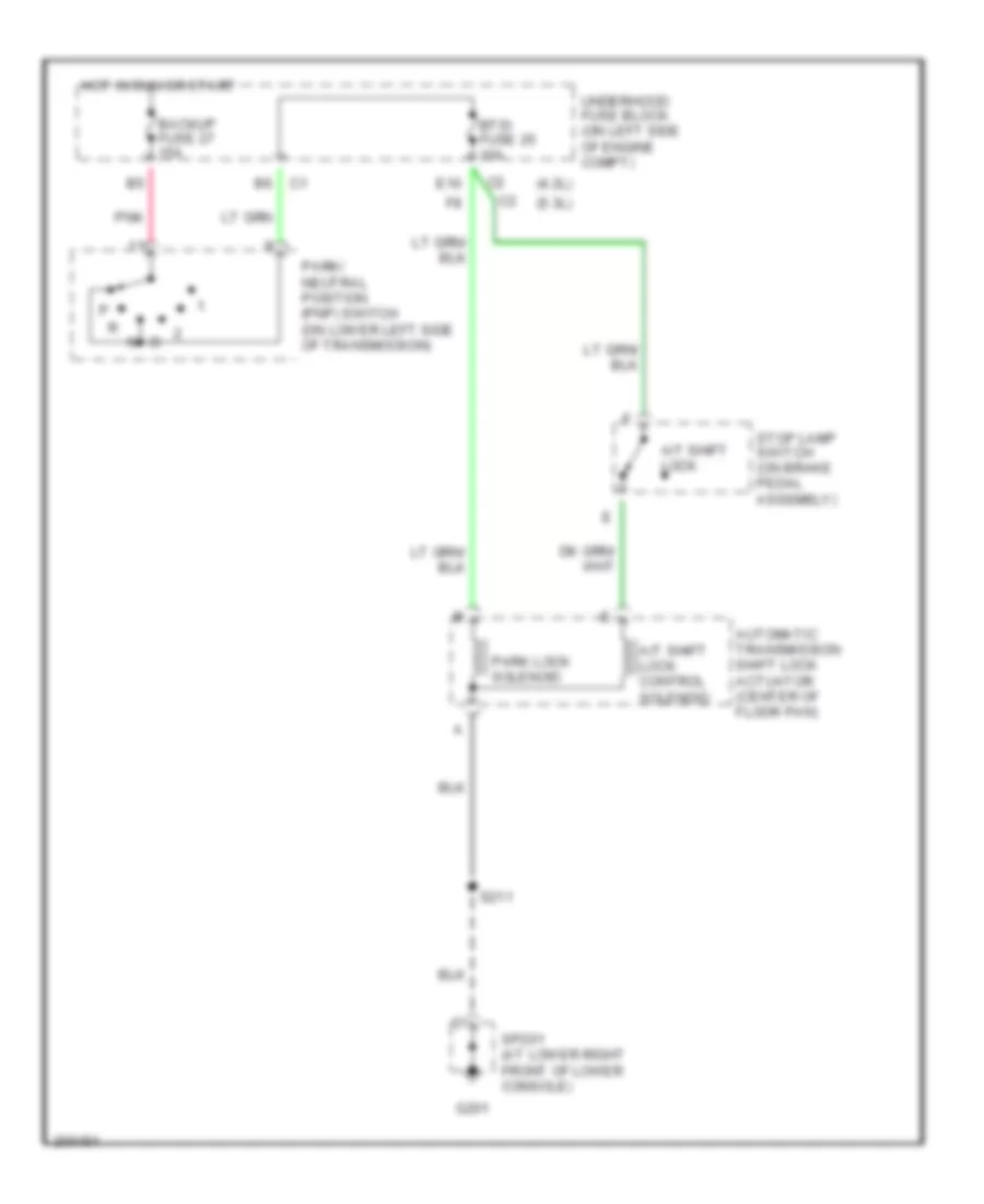 https://portal-diagnostov.com/license.html
Automotive Electricians Portal FZCO
Automotive Electricians Portal FZCO
https://portal-diagnostov.com/license.html
https://portal-diagnostov.com/license.html
Automotive Electricians Portal FZCO
Automotive Electricians Portal FZCOList of elements for Shift Interlock Wiring Diagram for Chevrolet TrailBlazer 2005:
- (4.2l)
- (5.3l)
- A/t shift lock
- A/t shift lock control solenoid
- Automatic transmission shift lock actuator (center of floor pan)
- Backup fuse 27 15a
- Btsi fuse 25 10a
- E10
- G201
- Hot in run or start
- Park lock solenoid
- Park/ neutral position (pnp) switch (on lower left side of transmission)
- Pnk
- S211
- Sp201 (at lower right front of lower console)
- Stop lamp switch (on brake pedal assembly)
- Underhood fuse block (on left side of engine compt)
STARTING/CHARGING
Charging Wiring Diagram for Chevrolet TrailBlazer 2005
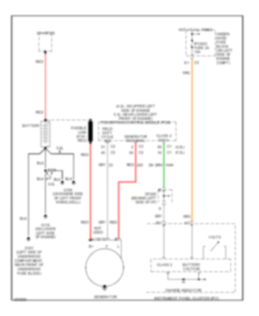 https://portal-diagnostov.com/license.html
Automotive Electricians Portal FZCO
Automotive Electricians Portal FZCO
https://portal-diagnostov.com/license.html
https://portal-diagnostov.com/license.html
Automotive Electricians Portal FZCO
Automotive Electricians Portal FZCOList of elements for Charging Wiring Diagram for Chevrolet TrailBlazer 2005:
- (4.2l)
- (4.2l: on upper left side of engine 5.3l: near lower left front of engine) powertrain control module (pcm)
- (5.3l)
- 4.2l
- 5.3l
- Battery
- Battery voltage
- Charge indicator
- Class 2
- Class 2 data
- Field duty cycle sig
- Fusible link (8 ga- red)
- G101 (left side of underhood compartment, near front of underhood fuse block)
- G106 (on engine side of left front wheelwell)
- G110 (on lower left side of engine)
- Generator
- Generator on signal
- Hot at all times
- Instrument panel cluster (ipc)
- Ipc/dic fuse 24 10a
- Not used
- Red
- S110
- Sp205 (behind left side of i/p)
- Starter
- Under- hood fuse block (on left side of engine compt)
- Volts
Starting Wiring Diagram for Chevrolet TrailBlazer 2005
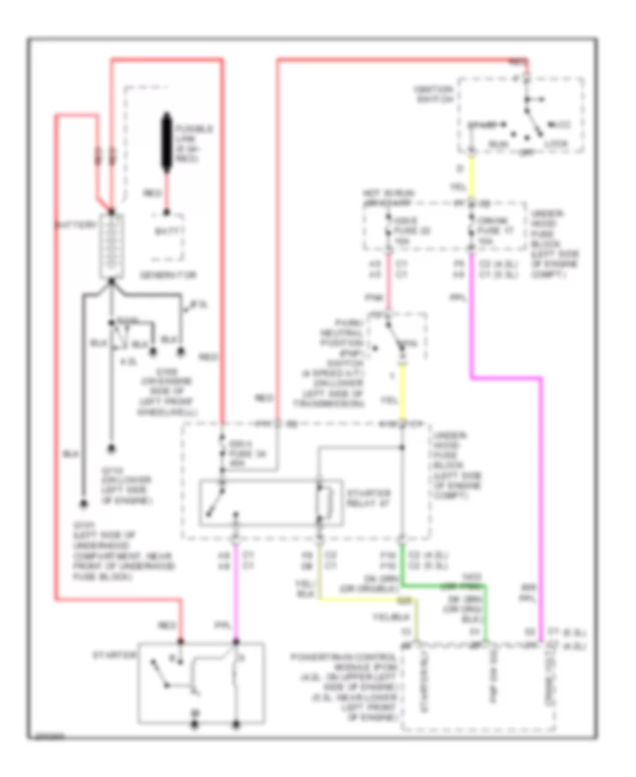 https://portal-diagnostov.com/license.html
Automotive Electricians Portal FZCO
Automotive Electricians Portal FZCO
https://portal-diagnostov.com/license.html
https://portal-diagnostov.com/license.html
Automotive Electricians Portal FZCO
Automotive Electricians Portal FZCOList of elements for Starting Wiring Diagram for Chevrolet TrailBlazer 2005:
- (4.2l)
- (4.2l) (5.3l)
- (5.3l)
- (or 1786)
- 4.2l
- 5.3l
- A10
- A5 a5
- A8 a8
- Acc
- Batt
- Battery
- C1 c1
- C1 crank volt
- C2 c1
- C2 c2
- Crank fuse 17 10a
- F10 f10
- F11
- F6 a6
- F8 d8
- Fusible link (8 ga- red)
- G101 (left side of underhood compartment, near front of underhood fuse block)
- G106 (on engine side of left front wheelwell)
- G110 (on lower left side of engine)
- Generator
- Hot in run or start
- Ign a fuse 34 40a
- Ign e fuse 22 10a
- Ignition switch
- Lock
- Off
- P/n
- Park/ neutral position (pnp) switch (4 speed a/t) (on lower left side of transmission)
- Pnk
- Pnp sw sig
- Powertrain control module (pcm) (4.2l: on upper left side of engine) (5.3l: near lower left front of engine)
- Red
- Run
- S110
- Start
- Starter
- Starter relay 47
- Starter rly
- Under- hood fuse block (left side of engine compt)
SUPPLEMENTAL RESTRAINTS
Supplemental Restraints Wiring Diagram (1 of 2) for Chevrolet TrailBlazer 2005
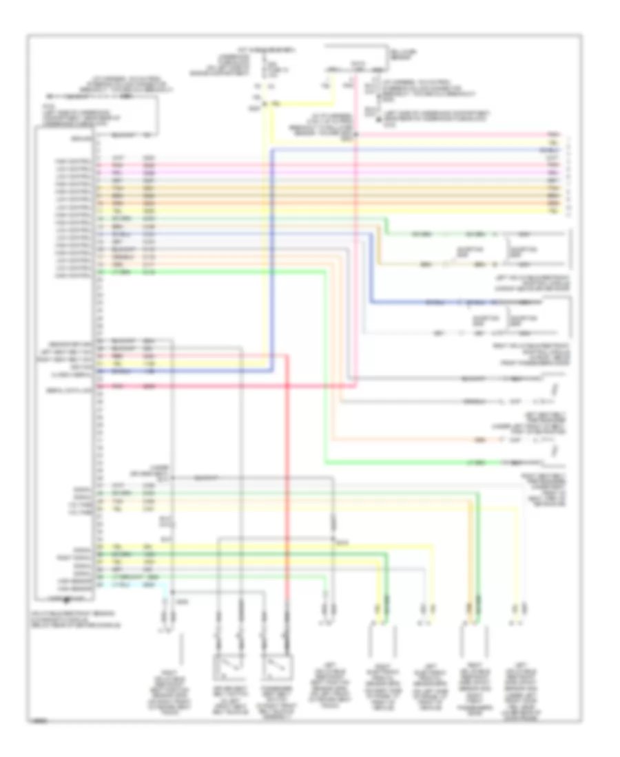 https://portal-diagnostov.com/license.html
Automotive Electricians Portal FZCO
Automotive Electricians Portal FZCO
https://portal-diagnostov.com/license.html
https://portal-diagnostov.com/license.html
Automotive Electricians Portal FZCO
Automotive Electricians Portal FZCOList of elements for Supplemental Restraints Wiring Diagram (1 of 2) for Chevrolet TrailBlazer 2005:
- (i/p harness, 16.5 cm from steering column connector breakout, toward dlc breakout) s202
- (in i/p harness, 5 cm (1.97 in) from breakout to rollover sensor, toward sdm) s203
- (in left front seat belt buckle)
- (left side of underhood compartment, near rear of underhood fuse block) g102
- (on left side of frame, at front of vehicle)
- (on right side of frame, at front of vehicle)
- (right front
- (under drivers seat) s310
- (under left front door trim, near lower rear of door frame)
- Bar
- Case ground
- Class 2 serial
- Data link
- Driver seat belt switch
- G102 (left side of underhood compartment, near rear of underhood fuse block)
- Gnd
- Ground
- High control
- High sensor
- Hot in run or start
- Ign 1
- Ignition
- Inflatable restraint sensing & diagnostic module (below rear of center console)
- Left electronic frontal sensor (efs)
- Left inflatable restraint roof rail module (in roof above driver door)
- Left inflatable restraint seat position sensor (sps) (on left front outboard seat track)
- Left inflatable restraint side impact sensor (sis)
- Left seat belt pretensioner (under left front of seat, part of retractor)
- Left seat belt sw
- Low control
- Nca
- Passenger seat belt switch (in right front belt buckle assembly)
- Passenger's door)
- Pnk
- Red
- Right electronic frontal sensor (efs)
- Right inflatable restraint roof rail module (in roof, above front passenger's door)
- Right inflatable restraint seat position sensor (sps) (on right front outboard seat track)
- Right inflatable restraint side impact sensor (sis)
- Right seat belt pretensioner (under right front of seat, part of retractor)
- Right seat belt sw
- Right signal
- Rollover sensor
- S220
- S308
- S315
- Sensor return
- Serial data link
- Shorting
- Shorting bar
- Signal
- Sir fuse 18 10a
- Tan
- Underhood fuse block (on left side of engine compartment)
- Voltage
Supplemental Restraints Wiring Diagram (2 of 2) for Chevrolet TrailBlazer 2005
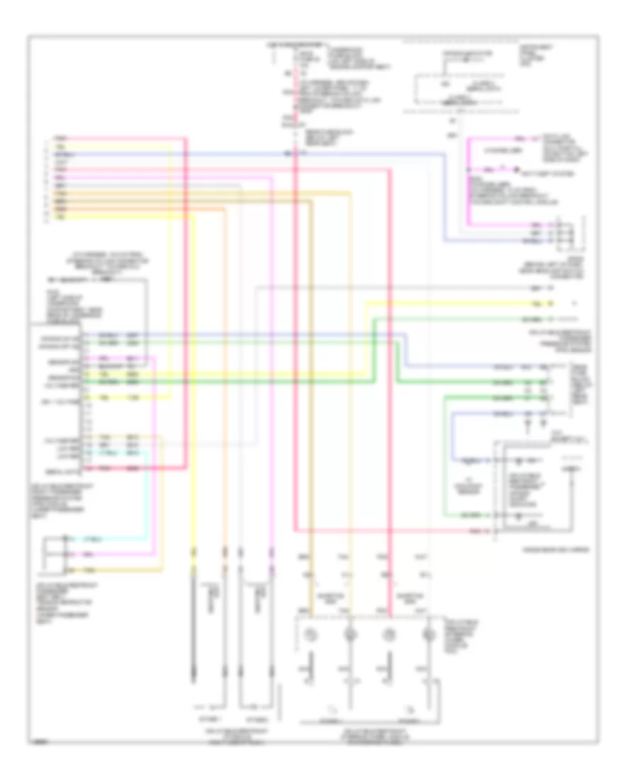 https://portal-diagnostov.com/license.html
Automotive Electricians Portal FZCO
Automotive Electricians Portal FZCO
https://portal-diagnostov.com/license.html
https://portal-diagnostov.com/license.html
Automotive Electricians Portal FZCO
Automotive Electricians Portal FZCOList of elements for Supplemental Restraints Wiring Diagram (2 of 2) for Chevrolet TrailBlazer 2005:
- (i/p harness, 16.5 cm from steering column connector breakout, toward dlc breakout) s202
- (i/p harness, above dash left lower panel, 11 cm from steering column breakout, toward data link connector breakout)
- (under passenger
- Air bag indicator
- Air bag off ind
- Air bag on ind
- Anti-theft system
- B12
- Bar shorting
- Class 2 serial data
- Data link connector (dlc) (partial) (on bottom left side of dash)
- E12
- Except xuv
- G102 (left side of underhood compartment, near rear of underhood fuse block)
- Gnd
- Hot in run or start
- Ign
- Ign 1 voltage
- Ign e fuse 22 10a
- Inflatable restraint front passenger presence system (pps) module (under passenger seat)
- Inflatable restraint i/p module (right side of dash)
- Inflatable restraint passenger air bag on/off indicator
- Inflatable restraint passenger presence system (pps) sensor
- Inflatable restraint passenger seat belt tension retractor
- Inflatable restraint steering wheel module (in steering wheel)
- Inflatable restraint steering wheel module coil
- Inside rearview mirror
- Instrument panel cluster (ipc)
- Logic
- Low ref
- Nca
- Off
- Pnk
- Rear fuse block (below left rear seat)
- S232 (w/immobilizer) (i/p harness, 10 cm from steering column breakout, toward shift control module)
- S239
- Seat)
- Sensor
- Sensor sig
- Serial data
- Shorting bar
- Sp205 (behind left of dash, near headlamp switch connector)
- Stage 1
- Stage 2
- Tan
- Underhood fuse block (on left side of engine compartment)
- Voltage ref
- W/ occupant sensor
- W/immobilizer
- Xuv
TRANSMISSION
Transfer Case Wiring Diagram, 2 Speed for Chevrolet TrailBlazer 2005
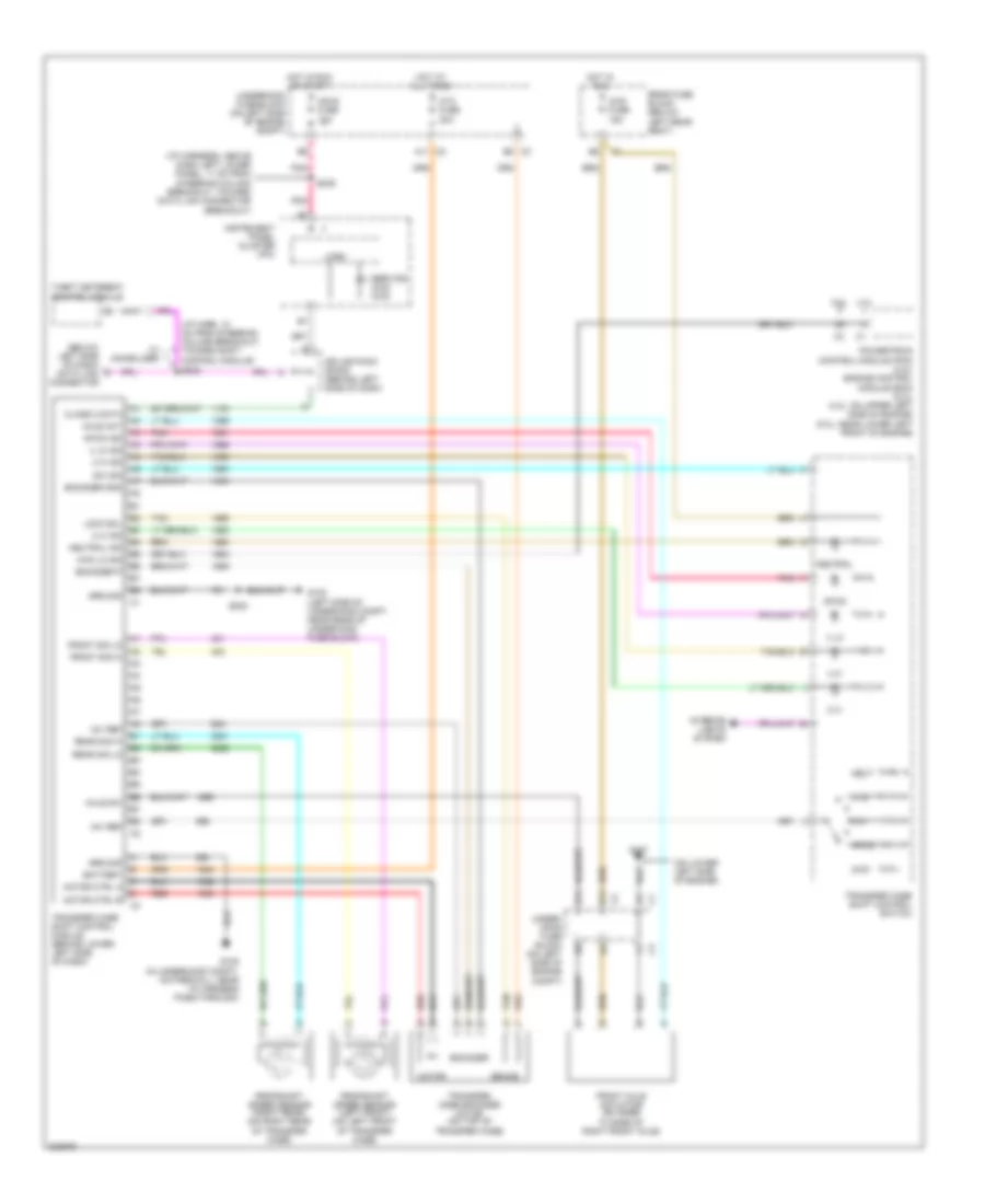 https://portal-diagnostov.com/license.html
Automotive Electricians Portal FZCO
Automotive Electricians Portal FZCO
https://portal-diagnostov.com/license.html
https://portal-diagnostov.com/license.html
Automotive Electricians Portal FZCO
Automotive Electricians Portal FZCOList of elements for Transfer Case Wiring Diagram, 2 Speed for Chevrolet TrailBlazer 2005:
- (below left side of dash) data link connector
- (i/p harn, 10 cm from steering column breakout, toward shift control module)
- (i/p harness, above dash left lower panel, 11 cm from steering column breakout, toward data link connector breakout)
- (on lower left side of engine)
- +5v ref
- 2 hi
- 2 hi ind
- 2wd
- 4 hi
- 4 hi ind
- 4 lo
- 4 lo ind
- 4.2l
- 4wd fuse 15a
- 4wd lo sig
- 5.3l
- Afwd
- Afwd ind
- Atc fuse 30a
- Axle act
- Axle sw
- B11
- Battery
- Brake
- C2 a11
- Class 2 data
- E11
- E5 c3
- Encoder
- Encoder gnd
- Encoder p
- Front axle actuator (on inner flange of right front axle)
- Front sig hi
- Front sig lo
- G102 (left side of underhood compt, near rear of underhood fuse block)
- G105 (in underhood compt, on firewall, near i/p harness pass-through)
- G107
- Ground
- Hot at all times
- Hot in run
- Hot in run or start
- Ing e fuse 10a
- Instrument panel cluster (ipc)
- Interior lights system
- Lock sol
- Logic
- Motor
- Motor ctrl a
- Motor ctrl b
- Neut
- Neutral
- Neutral ind
- Pnk
- Powertrain control module (pcm) (4.2l) engine control module (ecm) (5.3l) (4.2l: on upper left side of engine) (5.3l: near lower left front of engine)
- Propshaft speed sensor (left front) (on left front of transfer case)
- Propshaft speed sensor (right rear) (on right rear of transfer case)
- Rear fuse block (below left rear seat)
- Rear sig hi
- Rear sig lo
- Red
- S202
- S232
- S239
- Service 4wd/ awd
- Splice pack sp205 (behind left side of dash)
- Sw sig
- Tan
- Theft deterent control module
- Transfer case encoder motor (on top of transfer case)
- Transfer case shift control module (behind lower left side of dash)
- Transfer case shift control switch
- Under- hood fuse block (on left side of engine compt)
- Underhood fuse block (on left side of engine compt)
- W/ immobilizer
Transfer Case Wiring Diagram, Single Speed for Chevrolet TrailBlazer 2005
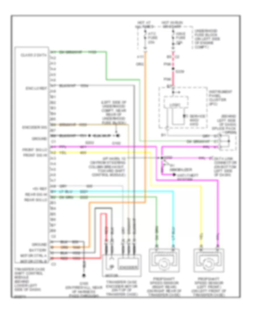 https://portal-diagnostov.com/license.html
Automotive Electricians Portal FZCO
Automotive Electricians Portal FZCO
https://portal-diagnostov.com/license.html
https://portal-diagnostov.com/license.html
Automotive Electricians Portal FZCO
Automotive Electricians Portal FZCOList of elements for Transfer Case Wiring Diagram, Single Speed for Chevrolet TrailBlazer 2005:
- (behind left side of dash) splice pack sp205
- (i/p harn, 10 cm from steering column breakout, toward shift control module)
- (left side of underhood compt, near rear of underhood fuse block)
- +5v ref
- A11
- Anti-theft system
- Atc fuse 25a
- B6 c2
- Battery
- Class 2 data
- Data link connector (on bottom left side of dash)
- Enc lo ref
- Encoder
- Encoder sig
- Front sig hi
- Front sig lo
- G102
- G105 (on firewall, near i/p harness pass-through)
- Ground
- Hot at all times
- Hot in run or start
- Ign e fuse 10a
- Instrument panel cluster (ipc)
- Logic
- Motor
- Motor ctrl a
- Motor ctrl b
- Nca
- Pnk
- Propshaft speed sensor (left front) (on left front of transfer case)
- Propshaft speed sensor (right rear) (on right rear of transfer case)
- Rear sig hi
- Rear sig lo
- Red
- S202
- S232
- S239
- Service 4wd/ awd
- Transfer case encoder motor (on top of transfer case)
- Transfer case shift control module (behind lower left side of dash)
- Underhood fuse block (on left side of engine compt)
- W/ immobilizer
4.2L VIN S
4.2L VIN S, A/T Wiring Diagram for Chevrolet TrailBlazer 2005
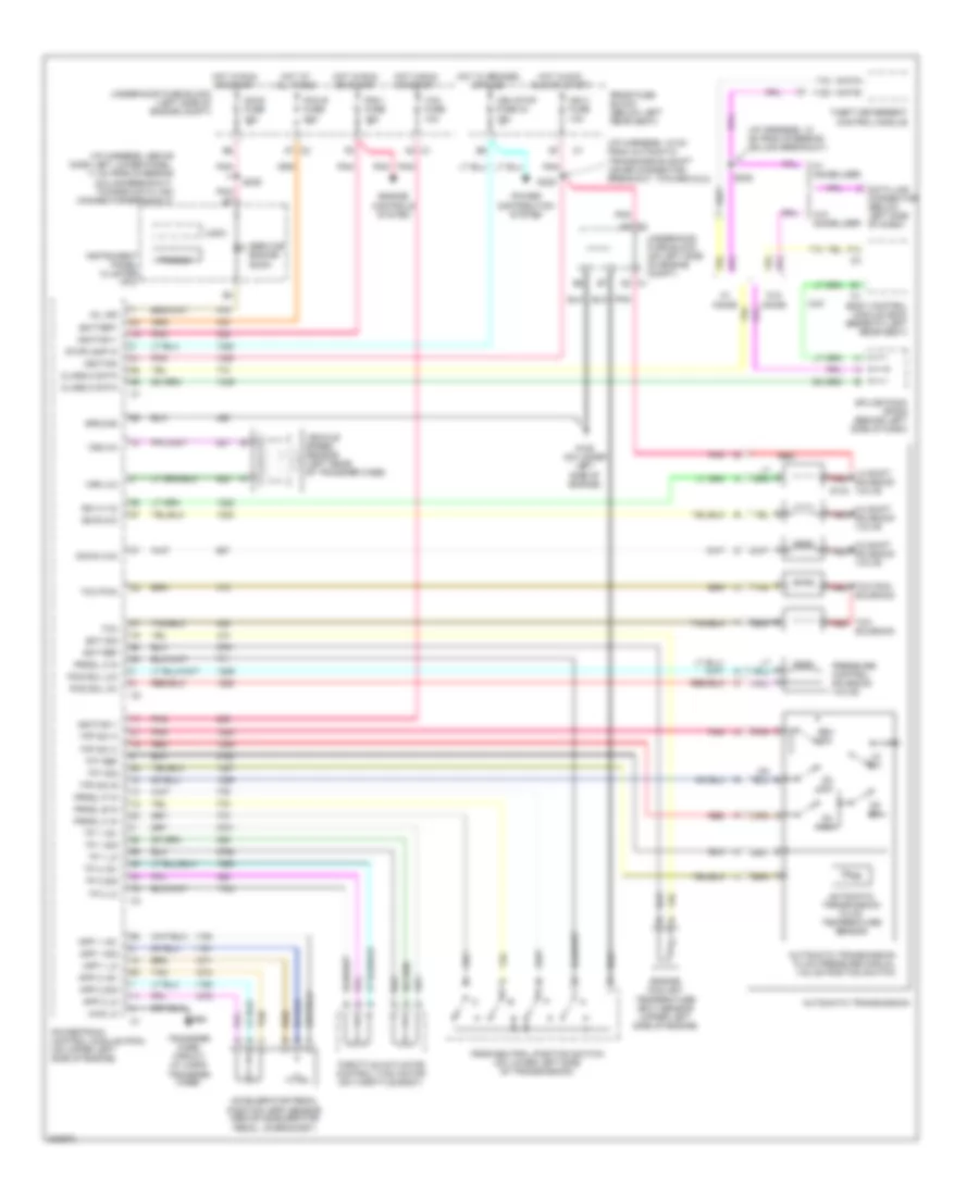 https://portal-diagnostov.com/license.html
Automotive Electricians Portal FZCO
Automotive Electricians Portal FZCO
https://portal-diagnostov.com/license.html
https://portal-diagnostov.com/license.html
Automotive Electricians Portal FZCO
Automotive Electricians Portal FZCOList of elements for 4.2L VIN S, A/T Wiring Diagram for Chevrolet TrailBlazer 2005:
- (i/p harness, 10 cm from steering column breakout)
- (i/p harness, 18 cm from automatic transmission shift lever connector breakout, toward dlc)
- (i/p harness, above dash left lower panel, 11 cm from steering column breakout, toward data link connector breakout)
- 1-2 shift red solenoid valve
- 2-3 shift red solenoid valve
- 3-2 shift red solenoid valve
- 4wd lo
- A2 c1
- Accelerator pedal position (app) sensor (above accelerator pedal, on bracket)
- App 1 +5v
- App 1 lo
- App 1 sig
- App 2 +5v
- App 2 lo
- App 2 sig
- Automatic transmission
- Automatic transmission fluid pressure manual valve position switch
- Automatic transmission fluid temperature sensor
- Battery
- Body control module (bcm) (beneath left rear seat)
- C2 a7
- Class 2 data
- D2 c1
- D2 sw
- D3 sw
- D4 sw
- Data link connector (below left side of dash)
- Down (3-2)
- E3 c2
- Ect ref
- Ect sig
- Engine controls system
- Engine coolant temperature (ect) sensor (upper left side of engine)
- F14
- G108 (on lower left side of engine)
- Ground
- Hot at all times
- Hot in acc run or start
- Hot in run or start
- Ign 0 fuse 10a
- Ignition
- Ignition 1
- Ing e fuse 10a
- Instrument panel cluster (ipc)
- Lo sw
- Logic
- Mil ind
- Park/neutral position switch (on lower left side of transmission)
- Pcm b fuse 20a
- Pcm i fuse 15a
- Pcs sol (hi)
- Pcs sol (lo)
- Pnk
- Power distribution system
- Powertrain control module (pcm) (on upper left side of engine)
- Pressure control solenoid valve
- Prnd321
- Prndl a in
- Prndl b in
- Prndl c in
- Prndl p in
- Rear fuse block (below left rear seat)
- Red
- Rev sw
- S133
- S232
- S239
- S320
- Service engine soon
- Solenoid
- Splice pack sp205 (behind left side of dash)
- Ss a (1-2)
- Ss b (2-3)
- Stoplamp in
- Tac fuse 10a
- Tan
- Tcc
- Tcc pmw red
- Tcc pwm
- Tcc red
- Tfp sw a
- Tfp sw b
- Tfp sw c
- Tft ref
- Tft sig
- Theft deterrent control module
- Throttle actuator control (tac) motor (on throttle body)
- Tp 1 +5v
- Tp 1 lo
- Tp 1 sig
- Tp 2 +5v
- Tp 2 lo
- Tp 2 sig
- Transfer case circuit (w/ 2-spd transfer case)
- Underhood fuse block (left side of engine compt)
- Underhood fuse block (on left side of engine compt)
- Veh stop fuse 34 15a
- Vehicle speed sensor (left rear of transfer case)
- Vss (hi)
- Vss (lo)
- W/ immob
- W/ immobilizer
- W/o immob
- W/o immobilizer
5.3L VIN M
5.3L VIN M, A/T Wiring Diagram (1 of 2) for Chevrolet TrailBlazer 2005
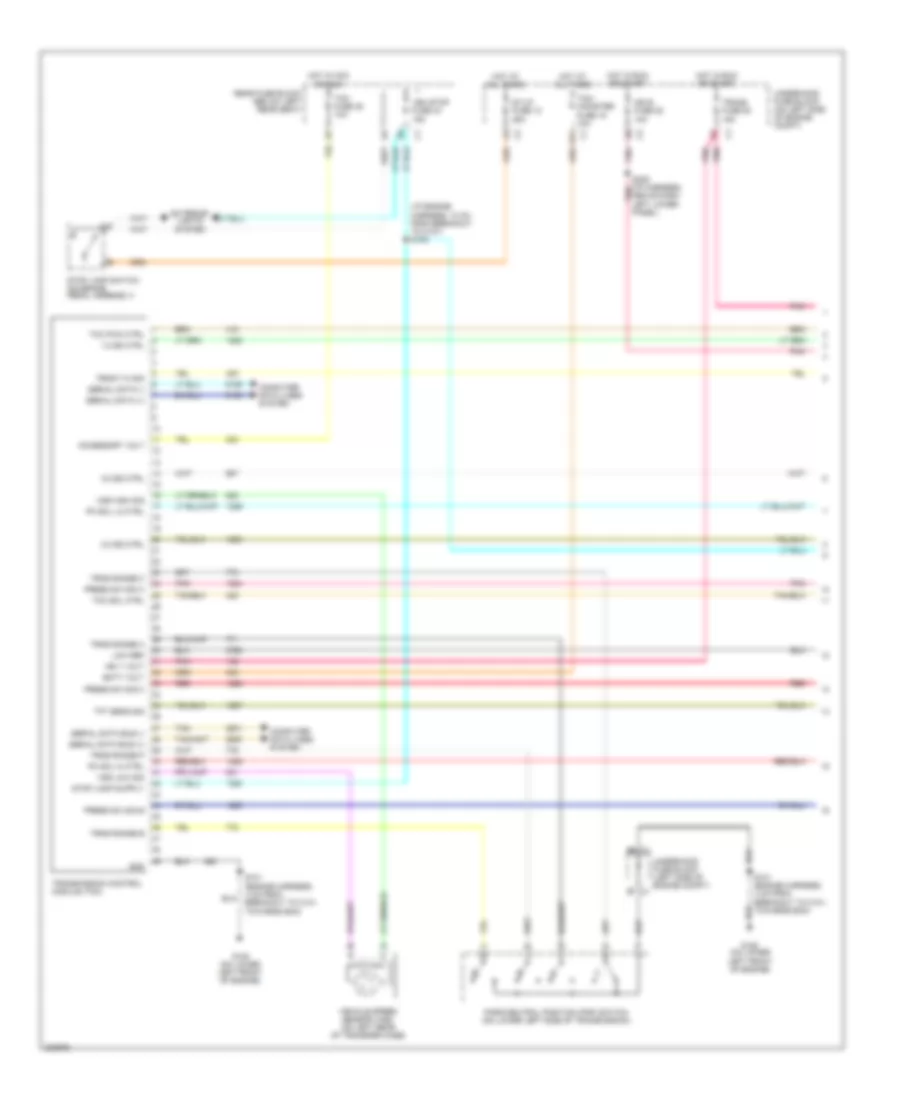 https://portal-diagnostov.com/license.html
Automotive Electricians Portal FZCO
Automotive Electricians Portal FZCO
https://portal-diagnostov.com/license.html
https://portal-diagnostov.com/license.html
Automotive Electricians Portal FZCO
Automotive Electricians Portal FZCOList of elements for 5.3L VIN M, A/T Wiring Diagram (1 of 2) for Chevrolet TrailBlazer 2005:
- (i/p engine harness, 10 cm from breakout to c107) s105
- 1-2 ss ctrl
- 2-3 ss ctrl
- 3-2 ss ctrl
- Above dash left lower panel)
- Accessory volt
- B11
- Batt volt
- Computer data lines system
- Exterior lights system
- Front hi sig
- G108 (on lower left front of engine)
- Gnd
- Hot at all times
- Hot in acc or run
- Hot in run or start
- Ign 1 volt
- Ign e fuse 22 10a
- Low ref
- Park/neutral position (pnp) switch (on lower left side of transmission)
- Pc sol hi ctrl
- Pc sol lo ctrl
- Pnk
- Pnk pnk
- Press sw sig a
- Press sw sig b
- Press sw sig c
- Rear fuse block (below left rear seat)
- Red
- S101 (engine harness, 4 cm from breakout to c101, towards ecm)
- S239 (i/p harness, pnk
- Serial data (+)
- Serial data (-)
- Serial data bus (+)
- Serial data bus (-)
- St/lp fuse 12 25a
- Stop lamp switch (on brake pedal assembly)
- Tan
- Tcc pwm ctrl
- Tcc sol ctrl
- Tcm fuse 35 10a
- Tcm/ canister fuse 15 10a
- Tft sens sig
- Trans fuse 53 15a
- Transmission control module (tcm)
- Trns range a
- Trns range b
- Trns range c
- Trns range p
- Underhood fuse block (left side of engine compt) c1
- Underhood fuse block (on left side of engine compt)
- Veh stop fuse 34 15a
- Vehicle speed sensor (vss) (on left rear of transfer case)
- Vss high sig
- Vss low sig
5.3L VIN M, A/T Wiring Diagram (2 of 2) for Chevrolet TrailBlazer 2005
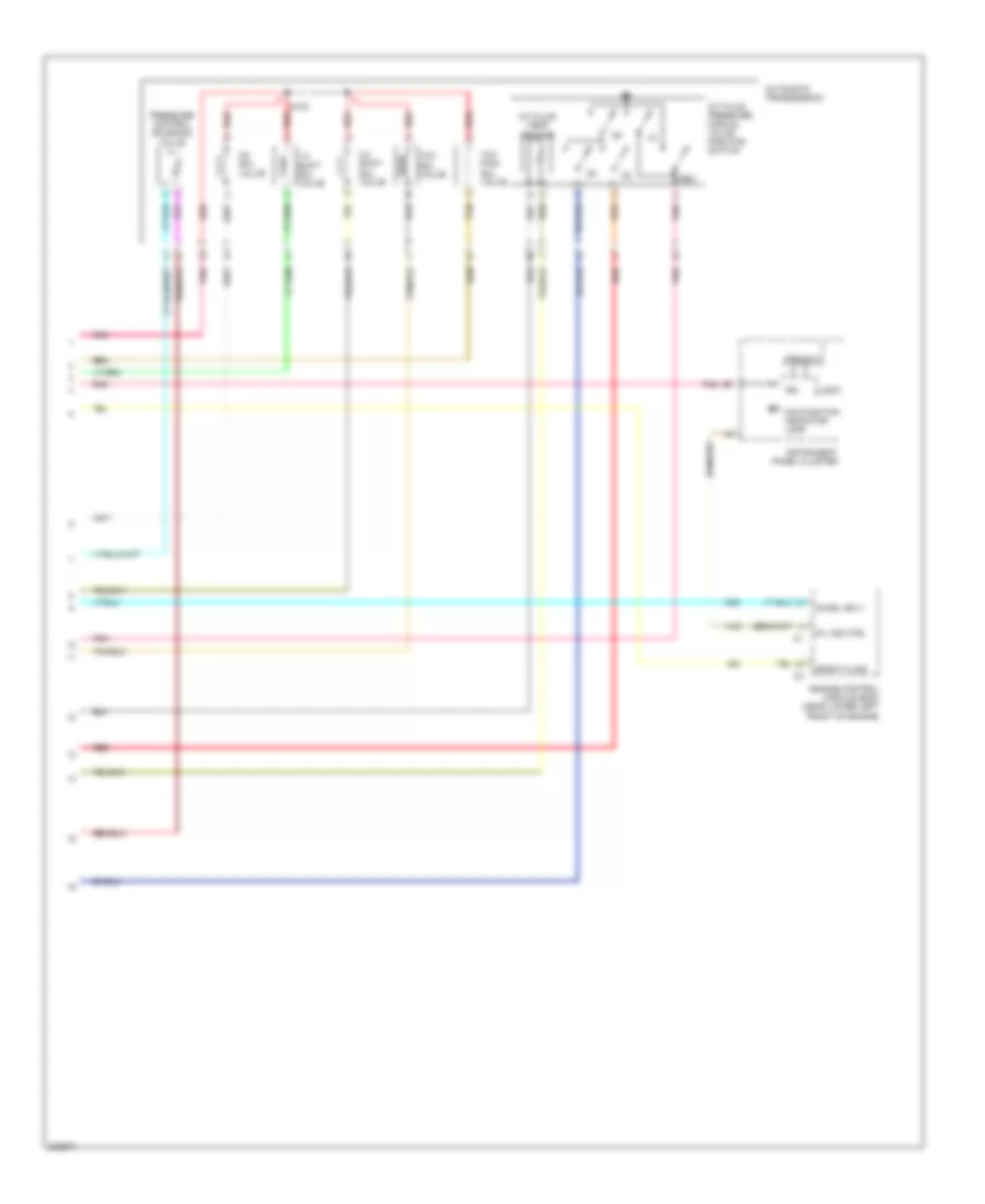 https://portal-diagnostov.com/license.html
Automotive Electricians Portal FZCO
Automotive Electricians Portal FZCO
https://portal-diagnostov.com/license.html
https://portal-diagnostov.com/license.html
Automotive Electricians Portal FZCO
Automotive Electricians Portal FZCOList of elements for 5.3L VIN M, A/T Wiring Diagram (2 of 2) for Chevrolet TrailBlazer 2005:
- 1-2 shift sol valve
- 2-3 shift sol valve
- 3-2 sol valve
- A/t fluid pressure manual valve position switch
- A/t fluid temp sensor
- Automatic transmission
- Chmsl sply
- Engine control module (ecm) (near lower left front of engine)
- Front hi sig
- Ign
- Instrument panel cluster
- Logic
- Malfunction indicator lamp
- Mil ind ctrl
- Pnk
- Pressure control solenoid valve
- Prnd321
- Red
- Rev
- S133
- Tan
- Tcc pwm sol valve
- Tcc sol valve
WARNING SYSTEMS
Warning Systems Wiring Diagram for Chevrolet TrailBlazer 2005
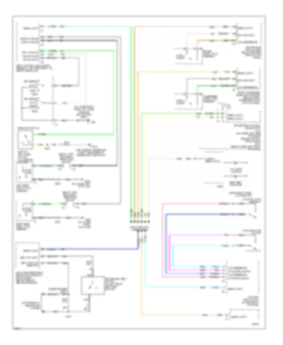 https://portal-diagnostov.com/license.html
Automotive Electricians Portal FZCO
Automotive Electricians Portal FZCO
https://portal-diagnostov.com/license.html
https://portal-diagnostov.com/license.html
Automotive Electricians Portal FZCO
Automotive Electricians Portal FZCOList of elements for Warning Systems Wiring Diagram for Chevrolet TrailBlazer 2005:
- (at lower right front of lower console) splice pack sp201
- (below left rear seat) rear fuse block
- (left side of underhood compt, near rear of underhood fuse block)
- (under drivers seat) s310
- 5.3l 4.2l
- A12
- Auto
- B10
- Belt sw input
- Body control module (bcm) (beneath left rear seat, on rear fuse block)
- Class 2 serial data
- Computer data lines system
- Door ajar
- Dr ajar input
- Driver door latch assembly
- Driver door module (ddm) (below driver's door switch panel)
- Driver seat belt switch (in left front seat belt buckle)
- Drl defeat
- F10
- Front passenger door module (fpdm) (below front passenger door switch panel)
- G102
- G201
- G302 (on lower left "b" pillar)
- G303 (on lower right "b" pillar)
- Hdlmp on sig
- Head
- Headlamp switch
- Ignition key alarm switch (in steering column)
- Inflatable restraint sensing & diagnostic module (sdm) (below rear of center console)
- Instrument panel cluster (ipc)
- Key in ign sw
- Left rear door latch assembly
- Liftgate ajar sw
- Liftgate latch assembly
- Liftgate module (lgm) (in center of liftgate)
- Liftglass ajar sw
- Liftglass ajar switch
- Logic
- Low reference
- Lr dr ajar sig
- Nca
- Park
- Passenger door latch assembly
- Powertrain control module (pcm) (4.2l) (on upper left side of engine) engine control module (ecm) (5.3l) (near lower left front of engine)
- Radio
- Right rear door latch assembly
- Rr dr ajar sig
- S227
- S302
- S303
- S315
- Seat belt indicator
- Seat position sens rtn
- Serial data
- Sw on input
- Tail gate ajar ind
- Tan
WIPER/WASHER
Front Wiper/Washer Wiring Diagram for Chevrolet TrailBlazer 2005
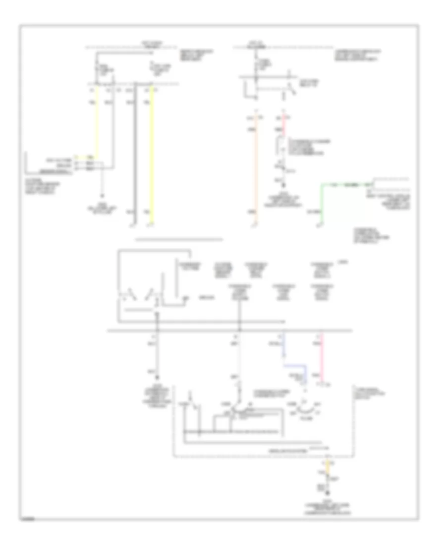 https://portal-diagnostov.com/license.html
Automotive Electricians Portal FZCO
Automotive Electricians Portal FZCO
https://portal-diagnostov.com/license.html
https://portal-diagnostov.com/license.html
Automotive Electricians Portal FZCO
Automotive Electricians Portal FZCOList of elements for Front Wiper/Washer Wiring Diagram for Chevrolet TrailBlazer 2005:
- A12
- Acc voltage
- Accessory voltage
- Body control module (under left rear seat, on fuse block)
- D10
- Frt wpr fuse 33 25a
- G102 (underhood, left side, near rear of underhood fuse block)
- G103 (underhood, on left side of radiator support)
- G105 (underhood, on firewall, near i/p harness pass through)
- G302 (on lower left "b" pillar)
- Ground
- Headlights system
- Hot at all times
- Hot in run or acc
- Logic
- Lsd
- Mist
- Off
- Outside moisture sensor (top center of front window)
- Outside moisture sensor signal 1
- Pnk
- Pulse
- Rain fuse 29 10a
- Rear fuse block (below left rear seat)
- Red
- S113
- S227
- Sensor signal 1
- Tan
- Turn signal multi-function switch
- Underhood fuse block (on left side of engine compartment)
- W/s wash relay 42
- Wash
- Wash fuse 9 15a
- Windshield washer fluid pump (on washer fluid reservoir)
- Windshield washer relay cntrl
- Windshield wiper high signal
- Windshield wiper motor (on upper center of firewall)
- Windshield wiper switch signal
- Windshield wiper switch signal 2
- Windshield wiper/ washer switch
Headlamp Washer Wiring Diagram for Chevrolet TrailBlazer 2005
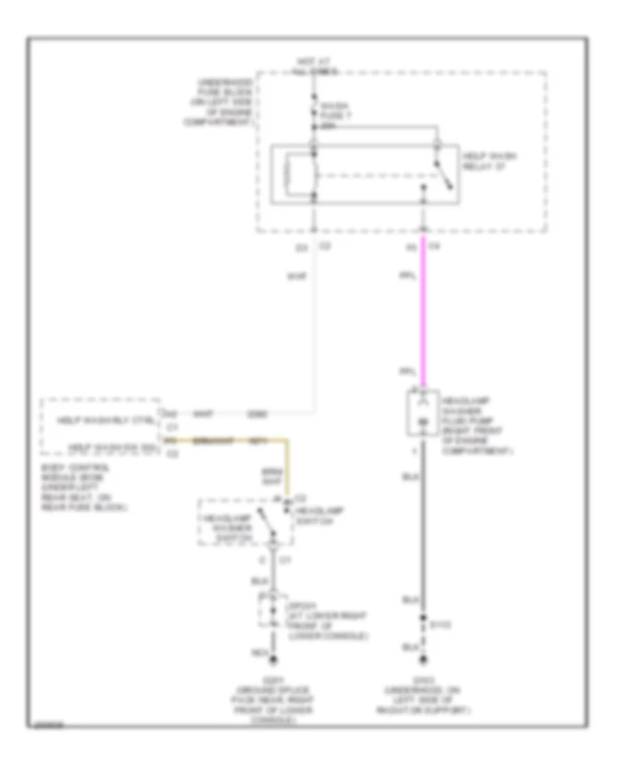 https://portal-diagnostov.com/license.html
Automotive Electricians Portal FZCO
Automotive Electricians Portal FZCO
https://portal-diagnostov.com/license.html
https://portal-diagnostov.com/license.html
Automotive Electricians Portal FZCO
Automotive Electricians Portal FZCOList of elements for Headlamp Washer Wiring Diagram for Chevrolet TrailBlazer 2005:
- Body control module (bcm) (under left rear seat, on rear fuse block)
- G103 (underhood, on left side of radiator support)
- G201 (ground splice pack near, right front of lower console)
- Hdlp wash relay 37
- Hdlp wash rly ctrl
- Hdlp wash sw sig
- Headlamp switch
- Headlamp washer fluid pump (right front of engine compartment)
- Headlamp washer switch
- Hot at all times
- Nca
- S113
- Sp201 (at lower right front of lower console)
- Underhood fuse block (on left side of engine compartment)
- Wash fuse 7 20a
Rear Wiper/Washer Wiring Diagram for Chevrolet TrailBlazer 2005
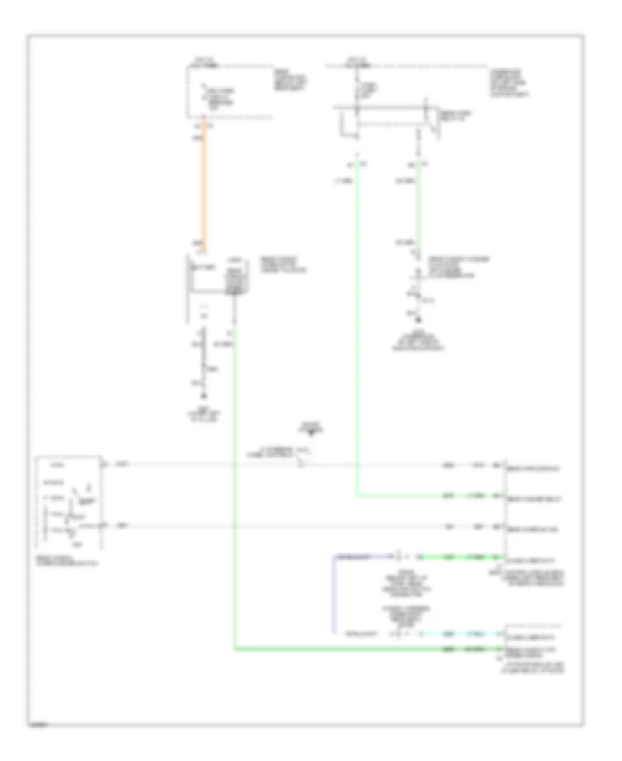 https://portal-diagnostov.com/license.html
Automotive Electricians Portal FZCO
Automotive Electricians Portal FZCO
https://portal-diagnostov.com/license.html
https://portal-diagnostov.com/license.html
Automotive Electricians Portal FZCO
Automotive Electricians Portal FZCOList of elements for Rear Wiper/Washer Wiring Diagram for Chevrolet TrailBlazer 2005:
- (in body harness, under right rear seat) sp306
- Battery
- Body control module (bcm) (under left rear seat on rear fuse block)
- Class 2 ser data
- Cont
- Dly
- G103 (underhood, on left side of radiator support)
- G401 (lower left "d" pillar)
- Hot at all times
- Liftgate module (lgm) (in center of liftgate)
- Logic
- Off
- Rear fuse block (below left rear seat)
- Rear wash relay 38
- Rear washer relay
- Rear window motor speed signal
- Rear window mtr speed signal c2
- Rear window washer fluid pump (on washer fluid reservoir)
- Rear window wiper motor (inside tailgate)
- Rear window wiper/washer switch
- Rear wiper sw sig
- Rear wpr/wshr sw
- Rr wiper circuit breaker 15a
- S113
- S901
- Sound systems
- Sp205 (behind left of dash, near headlamp switch connector)
- Underhood fuse block (on left side of engine compartment)
- W/ steering wheel controls
- Wash
- Wash fuse 7 20a

 Čeština
 Dansk
Dansk Deutsch
 Ελληνικά
 English
 English
 Español
 Suomi
Suomi Français
 Français
 עברית
עברית Hrvatski
 Magyar
 Italiano
 한국어
한국어 Nederlands
 Polski
 Português
 Português
 Română
 Русский
 Slovenčina
 Slovenščina
 Svenska
 Türkçe
 中文 (中国)
