AIR CONDITIONING
Automatic A/C Wiring Diagram for Ford Crown Victoria Police Interceptor 2002
 https://portal-diagnostov.com/license.html
Automotive Electricians Portal FZCO
Automotive Electricians Portal FZCO
https://portal-diagnostov.com/license.html
https://portal-diagnostov.com/license.html
Automotive Electricians Portal FZCO
Automotive Electricians Portal FZCO
List of elements for Automatic A/C Wiring Diagram for Ford Crown Victoria Police Interceptor 2002:
- (behind right kick panel) g201
- (bottom center right side of dash) s204
- (bottom right center of dash)
- (front of right front fender apron) g102
- (left front wheelwell)
- (not used)
- (under left side of dash) s226
- 87a
- A/c clutch cycling pressure switch (in right rear of engine compartment, on a/c accumulator)
- A/c clutch field coil (lower right front of engine)
- A/c clutch output
- A/c clutch relay
- A/c high pressure cut out switch (in right side of engine compartment, near battery junction box)
- Air bag sliding contact
- Amb temp sens input
- Ambient air temperature sensor (on front of upper radiator support)
- Audio/climate control system
- Battery
- Battery junction box (in right front of engine compartment, behind battery)
- Blend door (cool)
- Blend door (heat)
- Blend door actuator (behind right side of dash, on top of a/c plenum)
- Blend door pot gnd
- Blend dr feedback
- Blower mtr output
- Blower speed ctrl
- C220b
- C228a
- C228b
- Central junction box (below dash, left of steering column)
- Circuit breaker 17 30a
- Computer data lines system
- E/m converter
- Electronic automatic temperature control (eatc) module (behind center of dash)
- Engine control system
- Engine cooling fan motor (front of engine compt)
- Engine cooling fan relay
- English/ metric output
- Front blower motor
- Front blower motor speed controller (on right side of firewall, on evaporator assembly)
- Front panel illum
- Fuse 13 50a
- Fuse 15a
- Fuse 30a
- Ground
- High speed fan control relay
- Hot at all times
- Hot in run
- Ignition
- In car temp sens
- In-car temperature sensor (behind top center of dash)
- Instrument cluster (digital)
- Instrument illum
- Interior lights system
- Pcm power relay
- Powertrain control module (pcm) (in engine compartment, on left side of firewall)
- Red
- Reference voltage
- Relay center box 1 (left side of engine compartment)
- Relay center box 2 (right side of engine compt)
- Relay signal
- Right kick panel) g201
- S129
- S139 (left rear of engine compt)
- S157 (top right of engine)
- S204
- S227 (behind instrument cluster)
- S251 (behind center of dash)
- Scp data (-)
- Scp data bus (+)
- Sensor ground
- Sound system
- Sun load sensor (top right side of dash, above glove box)
- Sunload sens input
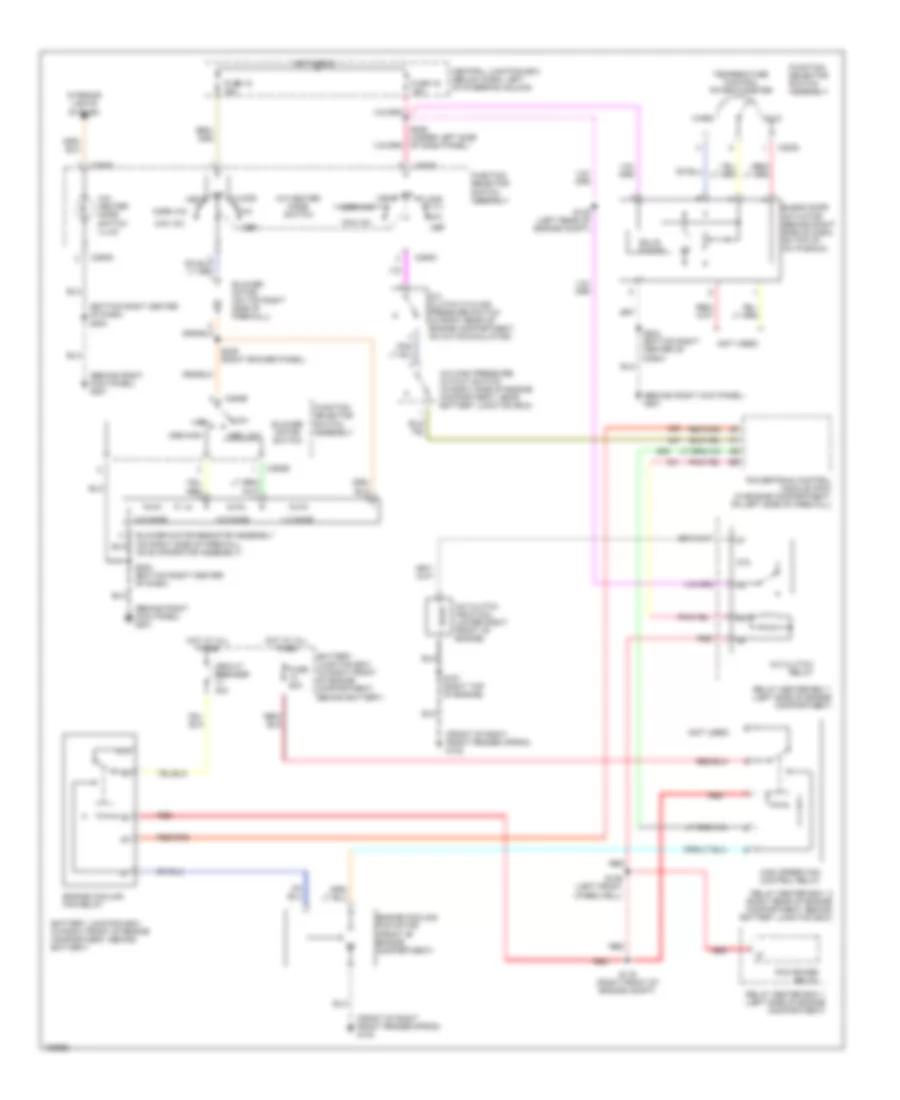
Manual A/C Wiring Diagram for Ford Crown Victoria Police Interceptor 2002
 https://portal-diagnostov.com/license.html
Automotive Electricians Portal FZCO
Automotive Electricians Portal FZCO
https://portal-diagnostov.com/license.html
https://portal-diagnostov.com/license.html
Automotive Electricians Portal FZCO
Automotive Electricians Portal FZCOList of elements for Manual A/C Wiring Diagram for Ford Crown Victoria Police Interceptor 2002:
- (behind right kick panel) g201
- (bottom right center of dash) s204
- (front of right front fender apron) g102
- (not used)
- 0.5 ohms
- 1.3 ohms
- 87a
- A/c clutch cycling pressure switch (in right rear of engine compartment, on a/c accumulator)
- A/c clutch field coil (lower right front of engine)
- A/c clutch relay
- A/c heater mode switch
- A/c high pressure cutout switch (in right side of engine compartment, near battery junction box)
- A/c- heater mode switch illum
- Battery junction box (in right front of engine compartment, behind battery)
- Blend door actuator (behind right side of dash, on top of a/c plenum)
- Blower motor (on top right side of firewall)
- Blower motor resistor assembly (on right side of firewall, on evaporator assembly)
- Blower motor switch
- C2020
- C294b
- C294c
- C294d
- Central junction box (below dash, left of steering column)
- Circuit breaker 30a
- Cold
- Def
- Engine cooling fan motor (front of engine compartment)
- Engine cooling fan relay
- Floor
- Function selector switch assembly
- Fuse 16 15a
- Fuse 18 30a
- Fuse 50a
- High
- High speed fan control relay
- Hot at all times
- Hot in run
- Interior lights system
- Low
- Max a/c
- Med high
- Med low
- Mix
- Norm a/c
- Off
- Pcm power relay
- Powertrain control module (pcm) (in engine compartment, on left side of firewall)
- Red
- Relay center box 2 (right rear of engine compartment, behind battery junction box)
- Relay center box 1 (left side of engine compartment)
- S116 (right front of engine compt)
- S129 (left front wheelwell)
- S139 (left rear of engine compt)
- S157 (right top of engine)
- S204 (bottom right center of dash)
- S226 (under left side of dash panel)
- S239 (right rocker panel)
- Solid state
- Temperature control potentiometer
- Vent
- Warm
ANTI-LOCK BRAKES
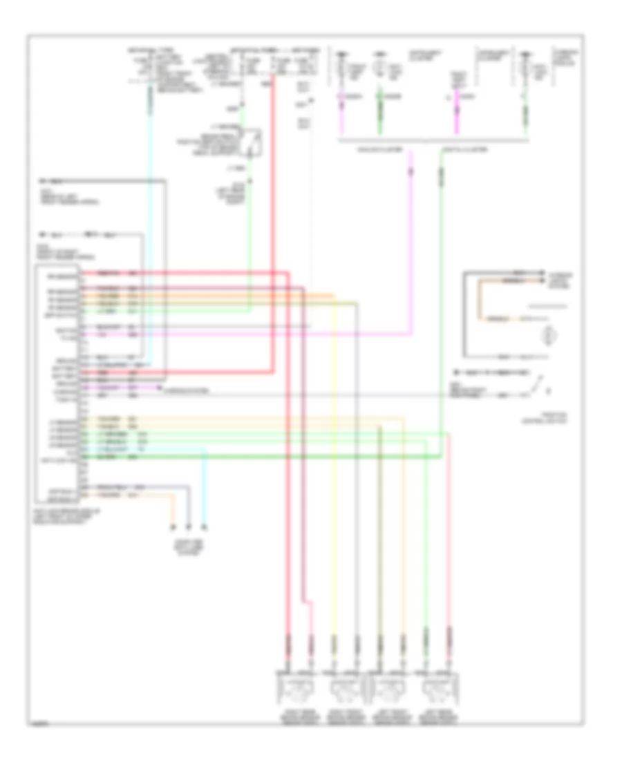
Anti-lock Brake Wiring Diagrams for Ford Crown Victoria Police Interceptor 2002
 https://portal-diagnostov.com/license.html
Automotive Electricians Portal FZCO
Automotive Electricians Portal FZCO
https://portal-diagnostov.com/license.html
https://portal-diagnostov.com/license.html
Automotive Electricians Portal FZCO
Automotive Electricians Portal FZCOList of elements for Anti-lock Brake Wiring Diagrams for Ford Crown Victoria Police Interceptor 2002:
- Analog cluster
- Anti- lock ind
- Anti-lock brake module (left front of upper radiator support)
- Anti-lock ind
- Battery
- Battery junction box (right front of engine compartment, behind battery)
- Bpp switch
- Brake pedal position (bpp) switch (top of brake pedal support)
- C220c
- C2220a
- C2220b
- Central junction box (left of steering column)
- Computer data lines system
- Digital cluster
- Dlc
- Fuse 10a
- Fuse 15a
- Fuse 30a
- Fuse 40a
- G101 (rear of left front fender apron)
- G102 (front of right front fender apron)
- G201 (behind right kick panel)
- Ground
- Hot at all times
- Hot in run
- Ign
- Ignition
- Instrument cluster
- Interior lights system
- Left front brake sensor (brake ass'y)
- Left rear brake sensor (brake ass'y)
- Lf sensor
- Lr sensor
- Nca
- Red
- Red/pnk
- Rf sensor
- Right front brake sensor (brake ass'y)
- Right rear brake sensor (brake ass'y)
- Rr sensor
- S112
- S132 (left rear of engine compt)
- S231
- S265
- Scp bus (+)
- Scp bus (-)
- Tc ind
- Tcsw in
- Tract asst ind
- Tract asst input
- Traction control switch
- Warning
- Warning lamps module
- Warning system
ANTI-THEFT
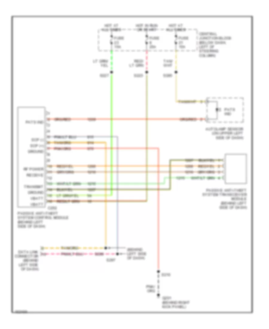
Anti-theft Wiring Diagram for Ford Crown Victoria Police Interceptor 2002
 https://portal-diagnostov.com/license.html
Automotive Electricians Portal FZCO
Automotive Electricians Portal FZCO
https://portal-diagnostov.com/license.html
https://portal-diagnostov.com/license.html
Automotive Electricians Portal FZCO
Automotive Electricians Portal FZCOList of elements for Anti-theft Wiring Diagram for Ford Crown Victoria Police Interceptor 2002:
- (behind left side of dash)
- Autolamp sensor (on upper left side of dash)
- C252
- Central junction block (below dash, left of steering column)
- Data link connector (behind left side of dash)
- Fuse 15a
- Fuse 25a
- G201 (behind right kick panel)
- Ground
- Hot at all times
- Hot in run or start
- Passive anti-theft system control module (behind left side of dash)
- Passive anti-theft system transceiver module (behind left side of dash)
- Pats ind
- Receive
- Rf power
- S210
- S223
- S227
- S285
- S296
- S297
- Scp (+)
- Scp (-)
- Transmit
- Vbatt
COMPUTER DATA LINES
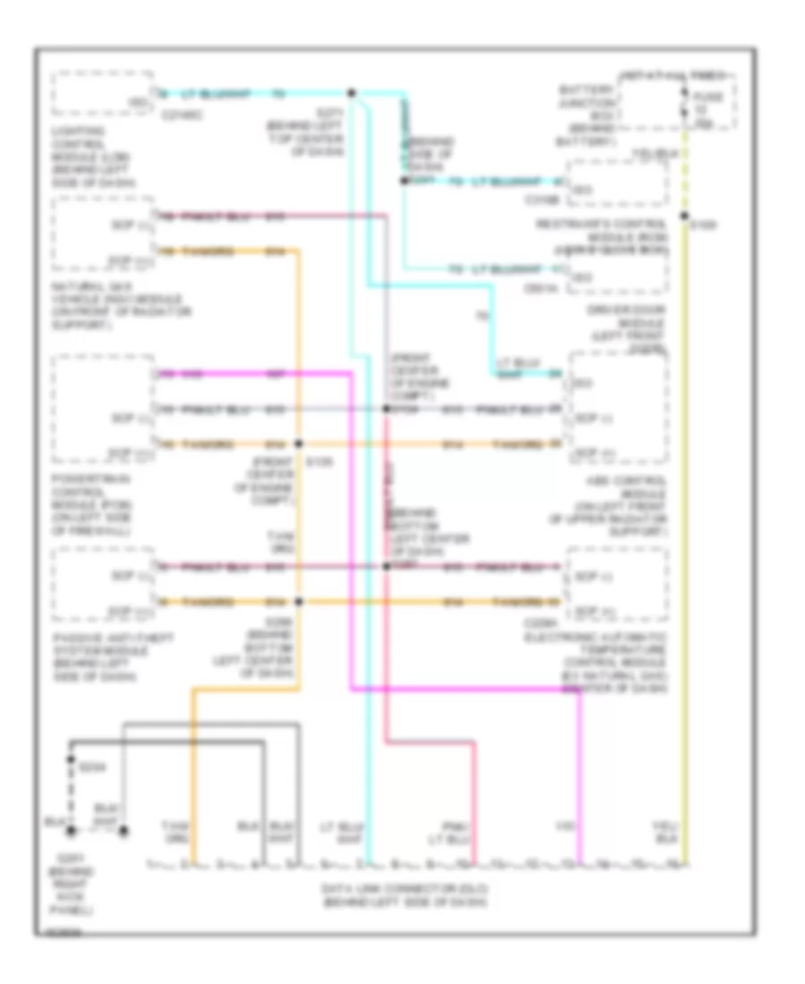
Computer Data Lines for Ford Crown Victoria Police Interceptor 2002
 https://portal-diagnostov.com/license.html
Automotive Electricians Portal FZCO
Automotive Electricians Portal FZCO
https://portal-diagnostov.com/license.html
https://portal-diagnostov.com/license.html
Automotive Electricians Portal FZCO
Automotive Electricians Portal FZCOList of elements for Computer Data Lines for Ford Crown Victoria Police Interceptor 2002:
- (behind bottom left center of dash) s297
- (behind side of dash) s241
- (front center of engine compt)
- (front center of engine compt) s134
- Abs control module (on left front of upper radiator support)
- Battery junction box (behind battery)
- C2145c
- C228a
- C310b
- C501a
- Data link connector (dlc) (behind left side of dash)
- Driver door module (left front door)
- Electronic automatic temperature control module (ex natural gas) (center of dash)
- Fuse 30a
- G201 (behind right kick panel)
- Hot at all times
- Iso
- Lighting control module (lcm) (behind left side of dash)
- Natural gas vehicle (ngv) module (on front of radiator support)
- Passive anti-theft system module (behind left side of dash)
- Powertrain control module (pcm) (on left side of firewall)
- Restraints control module (rcm) (above glove box)
- S100
- S135
- S204
- S271 (behind left top center of dash)
- S296 (behind bottom left center of dash)
- Scp (+)
- Scp (-)
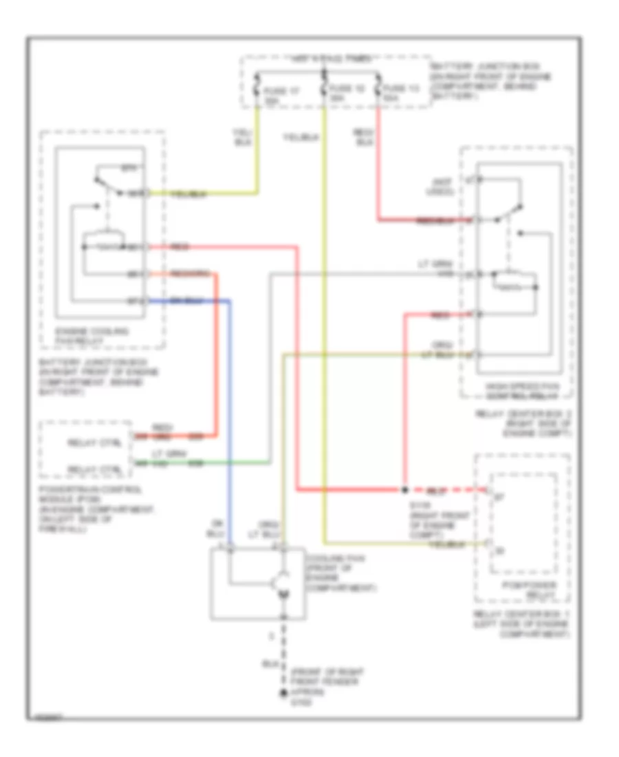
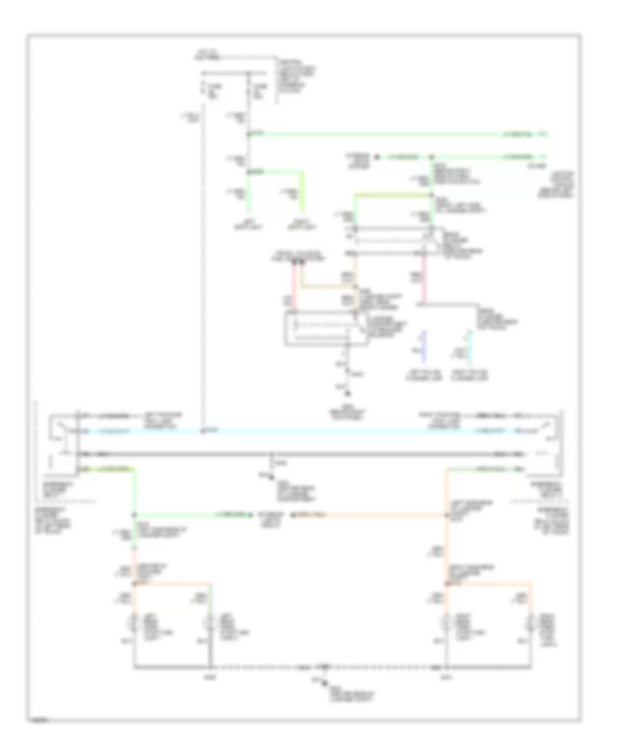
COOLING FAN
Cooling Fan Wiring Diagram for Ford Crown Victoria Police Interceptor 2002
 https://portal-diagnostov.com/license.html
Automotive Electricians Portal FZCO
Automotive Electricians Portal FZCO
https://portal-diagnostov.com/license.html
https://portal-diagnostov.com/license.html
Automotive Electricians Portal FZCO
Automotive Electricians Portal FZCOList of elements for Cooling Fan Wiring Diagram for Ford Crown Victoria Police Interceptor 2002:
- (front of right front fender apron) g102
- (not used)
- 87a
- Battery junction box (in right front of engine compartment, behind battery)
- Cooling fan (front of engine compartment)
- Engine cooling fan relay
- Fuse 12 30a
- Fuse 13 50a
- Fuse 17 30a
- High speed fan control relay
- Hot at all times
- Pcm power relay
- Powertrain control module (pcm) (in engine compartment, on left side of firewall)
- Red
- Relay center box 1 (left side of engine compartment)
- Relay center box 2 (right side of engine compt)
- Relay ctrl
- S116 (right front of engine compt)
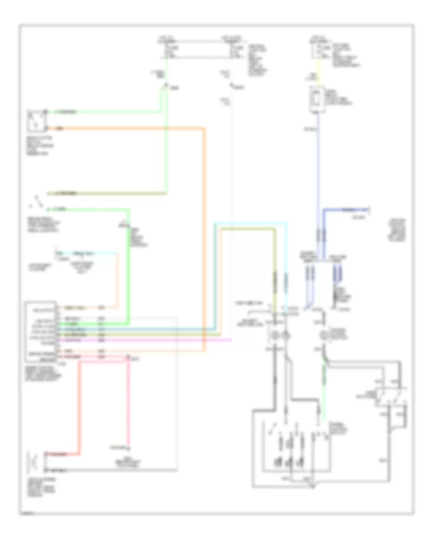
CRUISE CONTROL
Cruise Control Wiring Diagram for Ford Crown Victoria Police Interceptor 2002
 https://portal-diagnostov.com/license.html
Automotive Electricians Portal FZCO
Automotive Electricians Portal FZCO
https://portal-diagnostov.com/license.html
https://portal-diagnostov.com/license.html
Automotive Electricians Portal FZCO
Automotive Electricians Portal FZCOList of elements for Cruise Control Wiring Diagram for Ford Crown Victoria Police Interceptor 2002:
- (except feature car)
- (feature car)
- Air bag sliding contact
- Battery junction box (right front of engine compartment)
- Brake pedal position switch (top of brake pedal support)
- Brake press
- C122
- C2145a
- C218a
- C218c
- C220a
- Central junction box (below dash, left of steering column)
- Coast
- Ctrl sw rtn
- Ctrl sw sig
- Deactivator switch (below brake fluid reservoir)
- Electronic cluster only
- Except feature car
- Feature car
- Fuse 15a
- G201 (behind right kick panel)
- Ground
- Horn relay (in battery junction box)
- Horn switches
- Hot at all times
- Hot in acc or run
- Ind output
- Instrument cluster
- Lighting control module (behind left side of dash)
- Nca
- Off
- Ohms
- Power
- Resume
- S2009
- S210
- S254 (left nca rocker panel)
- S265
- S265 (on brake pedal support)
- Set/ accel
- Speed control servo assembly (left rear corner of engine compt)
- Speed control switch
- Stop lp sig
- Vehicle speed sensor (on left rear side of trans- mission)
- Vss input
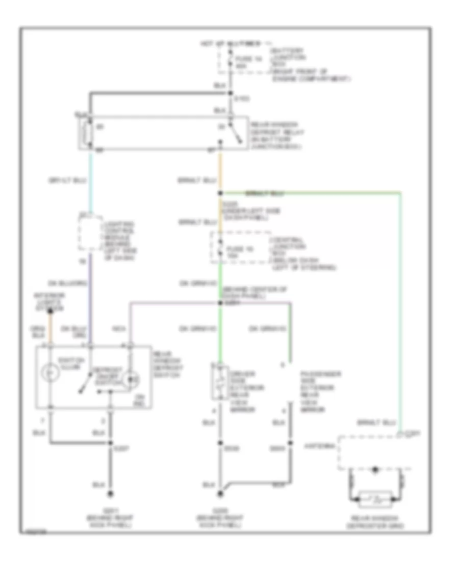
DEFOGGERS
Defogger Wiring Diagram for Ford Crown Victoria Police Interceptor 2002
 https://portal-diagnostov.com/license.html
Automotive Electricians Portal FZCO
Automotive Electricians Portal FZCO
https://portal-diagnostov.com/license.html
https://portal-diagnostov.com/license.html
Automotive Electricians Portal FZCO
Automotive Electricians Portal FZCOList of elements for Defogger Wiring Diagram for Ford Crown Victoria Police Interceptor 2002:
- (behind center of dash panel) s251
- Antenna
- Battery junction box (right front of engine compartment)
- C301
- Central junction box (below dash left of steering)
- Defrost on/off switch
- Driver side exterior rear view mirror
- Fuse 10 10a
- Fuse 14 40a
- G200 (behind right kick panel)
- G201 (behind right kick panel)
- Hot at all times
- Interior lights system
- Lighting control module (behind left side of dash)
- Nca
- On ind.
- Passenger side exterior rear view mirror
- Rear window defrost relay (in battery junction box)
- Rear window defrost switch
- Rear window defroster grid
- S153
- S207
- S225 (under left side dash panel)
- S500
- S600
- Switch illum.
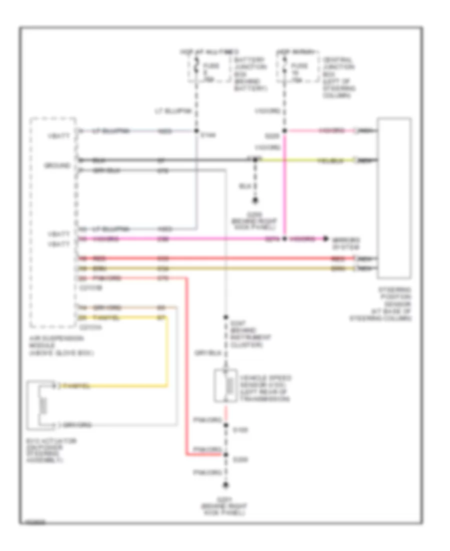
ELECTRONIC POWER STEERING
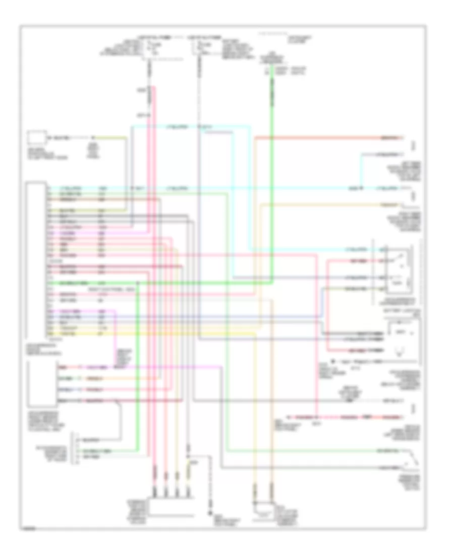
Electronic Power Steering Wiring Diagram, with Air Suspension for Ford Crown Victoria Police Interceptor 2002
 https://portal-diagnostov.com/license.html
Automotive Electricians Portal FZCO
Automotive Electricians Portal FZCO
https://portal-diagnostov.com/license.html
https://portal-diagnostov.com/license.html
Automotive Electricians Portal FZCO
Automotive Electricians Portal FZCOList of elements for Electronic Power Steering Wiring Diagram, with Air Suspension for Ford Crown Victoria Police Interceptor 2002:
- Air suspension module (above glove box)
- Battery junction box (behind battery)
- C2131a
- C2131b
- Central junction box (left of steering column)
- Evo actuator (on power steering assembly)
- Fuse 15a
- Fuse 30a
- G200 (behind right kick panel)
- G201 (behind right kick panel)
- Ground
- Hot at all times
- Hot in run
- Mirrors system
- Nca
- Red
- S105
- S144
- S200
- S208
- S226
- S247 (behind instrument cluster)
- S274
- Steering position sensor (at base of steering column)
- Vbatt
- Vehicle speed sensor (vss) (left rear of transmission)
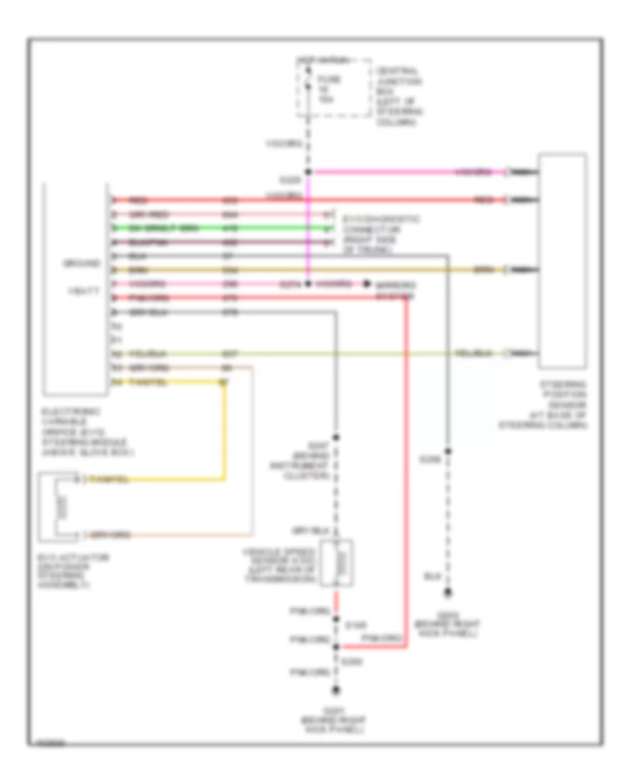
Electronic Power Steering Wiring Diagram, without Air Suspension for Ford Crown Victoria Police Interceptor 2002
 https://portal-diagnostov.com/license.html
Automotive Electricians Portal FZCO
Automotive Electricians Portal FZCO
https://portal-diagnostov.com/license.html
https://portal-diagnostov.com/license.html
Automotive Electricians Portal FZCO
Automotive Electricians Portal FZCOList of elements for Electronic Power Steering Wiring Diagram, without Air Suspension for Ford Crown Victoria Police Interceptor 2002:
- Central junction box (left of steering column)
- Electronic variable orifice (evo) steering module (above glove box)
- Evo actuator (on power steering assembly)
- Evo diagnostic connector (right side of trunk)
- Fuse 15a
- G200 (behind right kick panel)
- G201 (behind right kick panel)
- Ground
- Hot in run
- Mirrors system
- Nca
- Red
- S105
- S200
- S208
- S226
- S247 (behind instrument cluster)
- S274
- Steering position sensor (at base of steering column)
- Vbatt
- Vehicle speed sensor (vss) (left rear of transmission)
ELECTRONIC SUSPENSION
Electronic Suspension Wiring Diagram for Ford Crown Victoria Police Interceptor 2002
 https://portal-diagnostov.com/license.html
Automotive Electricians Portal FZCO
Automotive Electricians Portal FZCO
https://portal-diagnostov.com/license.html
https://portal-diagnostov.com/license.html
Automotive Electricians Portal FZCO
Automotive Electricians Portal FZCOList of elements for Electronic Suspension Wiring Diagram for Ford Crown Victoria Police Interceptor 2002:
- (behind instrument cluster) s247
- (behind right side of dash) s431
- (right kick panel)
- Air suspension compresor relay
- Air suspension compressor assembly (below air cleaner assembly)
- Air suspension height sensor (under rear of vehicle attached to control arm)
- Air suspension indicator
- Air suspension module (above glove box)
- Analog digital
- Battery junction box
- Battery junction box (right front of engine compt, behind battery)
- C2131a
- C2131b
- C2220a c220a
- Central junction box (below dash, left of steering column)
- Driver's door module (in left front door)
- Evo actuator (on power steering assembly)
- Evo diagnostic connector (right side of trunk)
- Fuse 15a
- Fuse 30a
- G102 (front of right fender apron)
- G200 (behind right kick panel)
- G201 (behind right kick panel)
- Hot at all times
- Instrument cluster
- Left rear shock absorber solenoid valve (top of left air spring)
- Nca
- Pressure reservoir control switch
- Red
- Right rear shock absorber solenoid valve (top of right air spring)
- S105
- S112
- S114
- S208
- S210
- S234
- S268 (right kick panel)
- S274
- S406
- S411
- Steering position sensor (base of steering column)
- Vehicle speed sensor (left rear side of transmission)
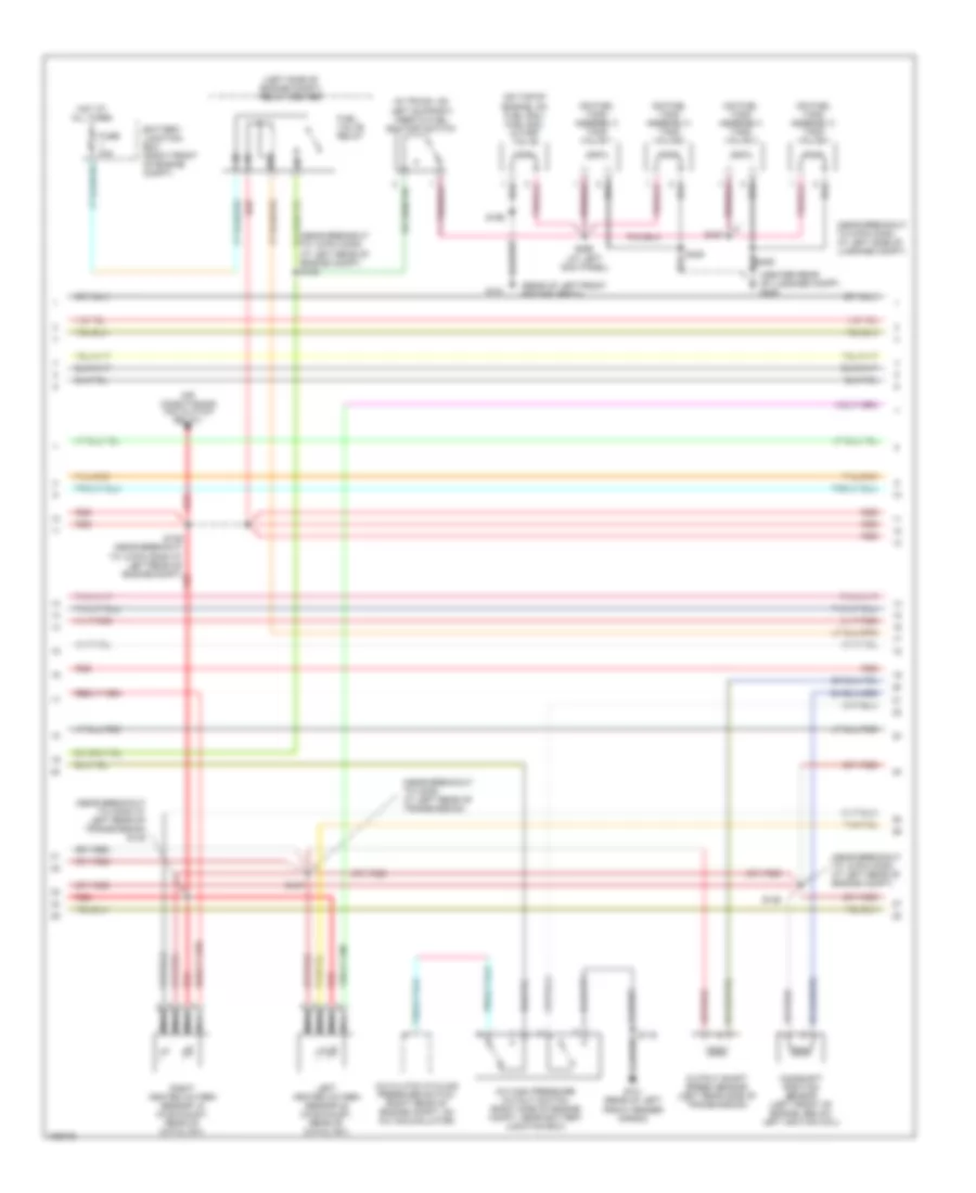
ENGINE PERFORMANCE
4.6L
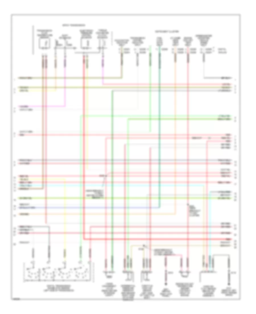
4.6L CNG, Engine Performance Wiring Diagrams (1 of 5) for Ford Crown Victoria Police Interceptor 2002
 https://portal-diagnostov.com/license.html
Automotive Electricians Portal FZCO
Automotive Electricians Portal FZCO
https://portal-diagnostov.com/license.html
https://portal-diagnostov.com/license.html
Automotive Electricians Portal FZCO
Automotive Electricians Portal FZCOList of elements for 4.6L CNG, Engine Performance Wiring Diagrams (1 of 5) for Ford Crown Victoria Police Interceptor 2002:
- (behind right kick panel) g201
- (near breakout to front crash sensor)
- (near ground at center rear of engine)
- (rear of left front fender apron)
- A/c cycling
- Battery junction box (right front of engine compt)
- Case gnd
- Central junction box (below dash, left of steering column)
- Ckp (+)
- Ckp (-)
- Coil 1
- Coil 3
- Coil 4
- Coil 5
- Coil 6
- Cooling fans (fan high rly)
- Cooling fans (fan low relay)
- Crankshaft position sensor (lower right front of engine)
- Crankshaft position sensor shield nca
- Cyl temp ind
- Data link (+)
- Data link (-)
- Data link connector (dlc) (behind left side of dash)
- Ect ind
- Egr vac reg
- Egr vacuum regulator solenoid valve (top center rear of engine)
- Eprom
- Fan high rly
- Fan low rly
- Fuel sol vlv
- Fuse 15a
- Fuse 25a
- Fuse 30a
- G101
- G101 (rear of left front fender apron)
- Hot at all times
- Hot in run or start
- Iat sens
- Ignition coils
- Intake air temperature sensor (left front of engine compt)
- Maf sig rtn
- Mil
- Nca
- Overdrive cancel switch (bottom of steering column)
- Pcm power diode
- Pcm power relay
- Powertrain control module (pcm) (in engine compt, on left side of firewall)
- Pwr gnd
- Radio noise capacitor (left front of engine, left side of left ignition coil)
- Red
- Relay center (left side of engine compt)
- Rt ho2s 12
- S100
- S103
- S119
- S134
- S135
- S151
- S223
- S276
- Shft sol a
- Shft sol b
- Tcil
- To fuel injector 8)
- Tr1
- Tr2
- Tr4
- Trans ctrl sw
- Trans temp
- Vss (+)
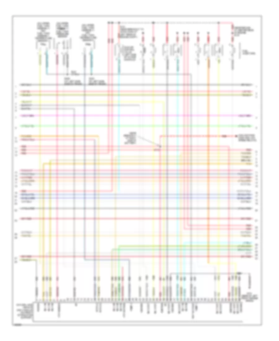
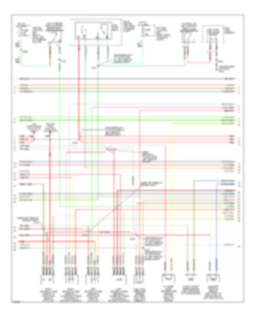
4.6L CNG, Engine Performance Wiring Diagrams (2 of 5) for Ford Crown Victoria Police Interceptor 2002
 https://portal-diagnostov.com/license.html
Automotive Electricians Portal FZCO
Automotive Electricians Portal FZCO
https://portal-diagnostov.com/license.html
https://portal-diagnostov.com/license.html
Automotive Electricians Portal FZCO
Automotive Electricians Portal FZCOList of elements for 4.6L CNG, Engine Performance Wiring Diagrams (2 of 5) for Ford Crown Victoria Police Interceptor 2002:
- 4r70w transmission
- C220a
- C220b
- Cylinder head temp input
- Digital transmission range (dtr) sensor (left side of transmission)
- Electronic pressure control solenoid
- Engine coolant temp input
- Engine coolant temperature sensor (top right front of engine)
- Fuel display input
- G101 (rear of left front fender apron)
- G201 (behind right kick panel)
- Inst cluster ground
- Instrument cluster
- Mal- function indicator input
- Mass air- flow sensor (behind air cleaner assembly)
- Power input
- R n
- Red
- S105
- S119
- S222 (near breakout to instrument cluster)
- S299 (near breakout to inst cluster)
- Shift solenoids
- Ssa
- Ssb
- Torque converter clutch solenoid
- Trans control indicator input
- Transmission fluid temperature sensor
- Vehicle speed input
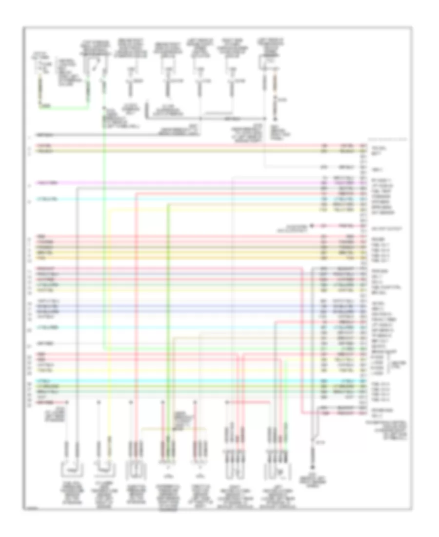
4.6L CNG, Engine Performance Wiring Diagrams (3 of 5) for Ford Crown Victoria Police Interceptor 2002
 https://portal-diagnostov.com/license.html
Automotive Electricians Portal FZCO
Automotive Electricians Portal FZCO
https://portal-diagnostov.com/license.html
https://portal-diagnostov.com/license.html
Automotive Electricians Portal FZCO
Automotive Electricians Portal FZCOList of elements for 4.6L CNG, Engine Performance Wiring Diagrams (3 of 5) for Ford Crown Victoria Police Interceptor 2002:
- (center rear of luggage compt) g400
- (in trunk, on left support) inertia fuel shutoff switch
- (left side of engine compt) relay center
- (near breakout to 12-pin conn at left rear of engine compt)
- (near breakout to 12-pin conn at left rear of engine compt) s130
- (near breakout to 2-pin conn at left side of luggage compt)
- (near breakout to conn at left rear of transmission)
- (near breakout to conn at left rear of transmission) s148
- (on fuel tank assembly) tank valve 1
- (on fuel tank assembly) tank valve 2
- (on fuel tank assembly) tank valve 3
- (on fuel tank assembly) tank valve 4
- (on top of engine, on fuel rail) fuel rail cutoff valve
- (rear of left front fender apron)
- A/c clutch cycling pressure switch (right rear of engine compt, on a/c accumulator)
- A/c high pressure cutout switch (right side of engine compt, near battery junction box)
- Air conditioning (a/c clutch relay)
- Battery junction box (right front of engine compt)
- Camshaft position sensor (left front of engine, below left ignition coil)
- Fuel valve relay
- Fuse 20a
- G101
- G101 (rear of left front fender apron)
- Hot at all times
- Left heated oxygen sensor 22 (in exhaust, rear of catalyst)
- Nca
- Output shaft speed sensor (left rear side of transmission)
- Red
- Right heated oxygen sensor 12 (in exhaust, rear of catalyst)
- S119
- S125
- S129 (near breakout to 12-pin conn at left rear of engine compt)
- S147
- S156
- S298 (at left kick panel)
- S427
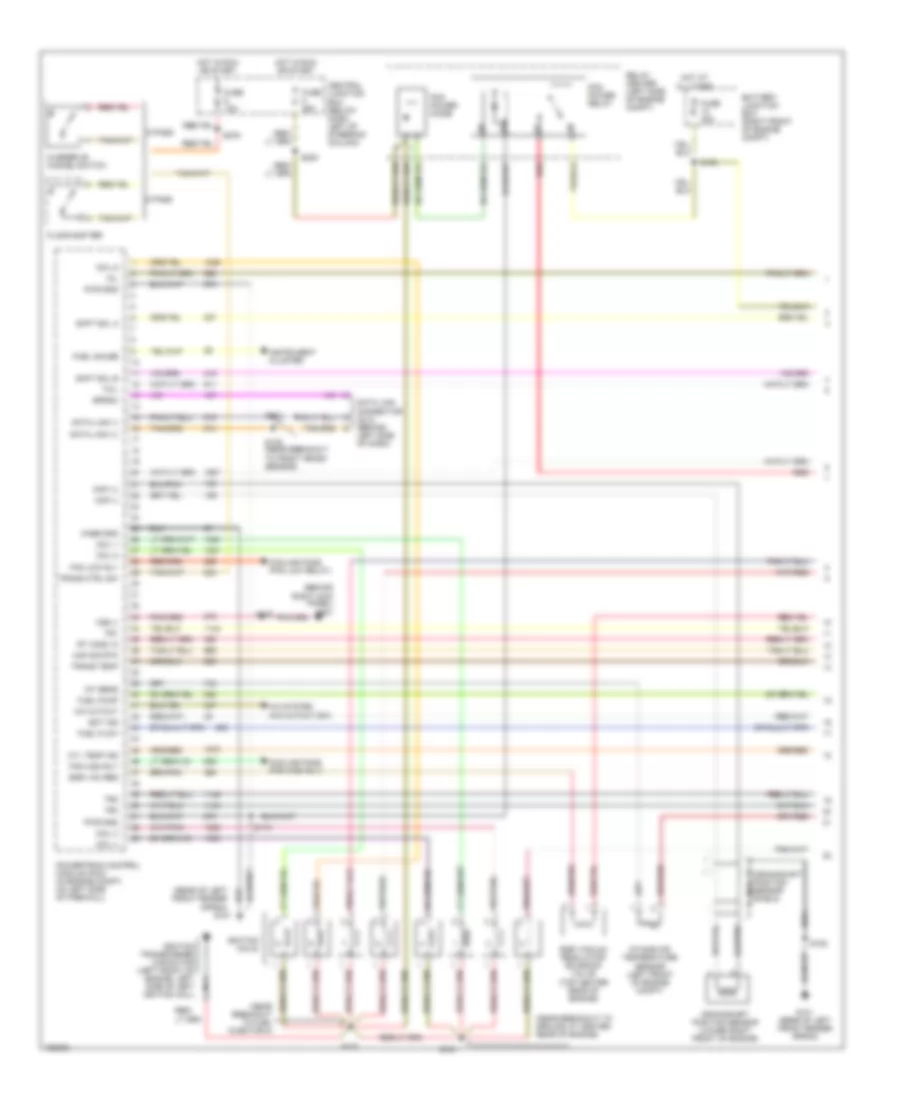
4.6L CNG, Engine Performance Wiring Diagrams (4 of 5) for Ford Crown Victoria Police Interceptor 2002
 https://portal-diagnostov.com/license.html
Automotive Electricians Portal FZCO
Automotive Electricians Portal FZCO
https://portal-diagnostov.com/license.html
https://portal-diagnostov.com/license.html
Automotive Electricians Portal FZCO
Automotive Electricians Portal FZCOList of elements for 4.6L CNG, Engine Performance Wiring Diagrams (4 of 5) for Ford Crown Victoria Police Interceptor 2002:
- (at left side side of trunk)
- (near breakout at right side of battery)
- (near ground at center rear of engine) s143
- (on upper fuel tank assembly) ngv fuel tank assembly temperature sensor 1
- (on upper fuel tank assembly) ngv fuel tank pressure sensor
- (on upper fuel tank assembly) ngv fuel tank temperature sensor 2
- Cooling fans (high and low speed relays)
- Data (+)
- Data (-)
- Ftp return
- Ftp sensor
- Fuel injectors
- G101 (rear of left front fender apron)
- Ground
- I/p
- Idle air control valve (left side of intake manifold)
- Ignition
- Inj 1 in
- Inj 1 out
- Inj 2 in
- Inj 2 out
- Inj 3 in
- Inj 3 out
- Inj 4 in
- Inj 4 out
- Inj 5 in
- Inj 5 out
- Inj 6 in
- Inj 6 out
- Inj 7 in
- Inj 7 out
- Inj 8 in
- Inj 8 out
- Natural gas vehicle (ngv) module (on front of radiator support)
- Power
- Red
- Red/pnk
- Ref voltage
- S116
- S131 (near breakout to 42-pin conn at left rear of engine compt)
- S141
- S429
- S430
- Tan
- Tan/red
- Temp 1
- Temp 2
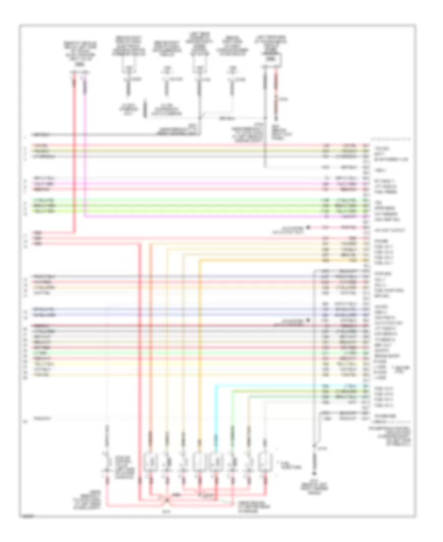
4.6L CNG, Engine Performance Wiring Diagrams (5 of 5) for Ford Crown Victoria Police Interceptor 2002
 https://portal-diagnostov.com/license.html
Automotive Electricians Portal FZCO
Automotive Electricians Portal FZCO
https://portal-diagnostov.com/license.html
https://portal-diagnostov.com/license.html
Automotive Electricians Portal FZCO
Automotive Electricians Portal FZCOList of elements for 4.6L CNG, Engine Performance Wiring Diagrams (5 of 5) for Ford Crown Victoria Police Interceptor 2002:
- (behind right side of dash) air suspension module
- (behind right side of dash) electronic variable orifice steering module
- (left rear of engine compt) speed control actuator
- (left rear of transmission) vehicle speed sensor
- (near breakout to right h2os 11) s126
- (right side of dash) warning buzzer/ chime module module
- (top of brake pedal support) brake pedal position switch
- A/c system (a/c clutch rly)
- A/c wot cutout
- Batt
- Brake on/off
- C122
- C2131b
- C2156
- C2230
- Cam pos in
- Central junction box (below dash, left of steering column)
- Cht sensor
- Coil 2
- Coil 7
- Coil 8
- Cylinder head temperature sensor (top left front of engine)
- Differential pressure feedback egr sensor (right side of intake manifold)
- Dpfe sens
- Dtr sens
- Epc sol
- Fan rly feed
- Fuel inj 1
- Fuel inj 2
- Fuel inj 3
- Fuel inj 4
- Fuel inj 5
- Fuel inj 6
- Fuel inj 7
- Fuel inj 8
- Fuel pump ctrl
- Fuel rail pressure transducer sensor (on top of engine)
- Fuel temp
- Fuse 15a
- G101 (rear of left front fender apron)
- G201 (behind right kick panel)
- Heater ctrl
- Hot at all times
- Iac sol
- Injection pressure sensor (on top of engine)
- Ip sensor
- L ho2s
- Left heated oxygen sensor 21 (lower left rear of engine, in exhaust manifold)
- Lft ho2s 21
- Lft ho2s 22
- Maf sens in
- Nca
- Oss (+)
- Power
- Power gnd
- Powertrain control module (pcm) (in engine compt, on left side of firewall)
- Pwr gnd
- R ho2s
- Red
- Red/pnk
- Ref volt
- Right heated oxygen sensor 11 (lower right rear of engine, in exhaust manifold)
- Rt ho2s 11
- S105
- S109 (near breakout to 12-pin conn at left rear of engine compt)
- S119
- S123 (at lower left rear of engine)
- S247 (near breakout to front control unit)
- S265
- Sig rtn
- Tan
- Tan/red
- Tcc sol
- Throttle position sensor (left side of throttle body)
- Tp sens in
- Vss (+)
- Vss (-)
- W/ air suspension & evo steering
- W/ evo steering only
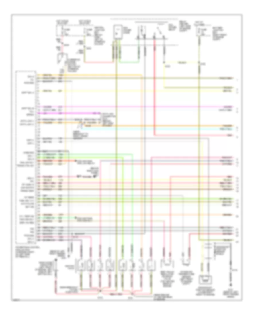
4.6L, Engine Performance Wiring Diagrams (1 of 4) for Ford Crown Victoria Police Interceptor 2002
 https://portal-diagnostov.com/license.html
Automotive Electricians Portal FZCO
Automotive Electricians Portal FZCO
https://portal-diagnostov.com/license.html
https://portal-diagnostov.com/license.html
Automotive Electricians Portal FZCO
Automotive Electricians Portal FZCOList of elements for 4.6L, Engine Performance Wiring Diagrams (1 of 4) for Ford Crown Victoria Police Interceptor 2002:
- (behind right kick panel) g201
- (near breakout to ground at center rear of engine)
- (rear of left front fender apron)
- 5 pass
- 6 pass
- A/c cutout
- A/c system (a/c cutout sw)
- Battery junction box (right front of engine compt)
- Case gnd
- Central junction box (below dash, left of steering column)
- Ckp (+)
- Ckp (-)
- Coil 1
- Coil 3
- Coil 4
- Coil 5
- Coil 6
- Cooling fans (fan high rly)
- Cooling fans (fan low relay)
- Crankshaft position sensor (lower right front of engine)
- Crankshaft position sensor shield
- Cyl temp ind
- Data link (+)
- Data link (-)
- Data link connector (dlc) (behind left side of dash)
- Ect ind
- Egr vac reg
- Egr vacuum regulator solenoid valve (top center rear of engine)
- Eprom
- Fan high rly
- Fan low rly
- Floor shifter
- Fuel flow
- Fuel gauge
- Fuel pump
- Fuse 15a
- Fuse 25a
- Fuse 30a
- G101
- G101 (rear of left front fender apron)
- Hot at all times
- Hot in run or start
- Iat sens
- Ignition coils
- Ignition transformer capacitor (left front of engine, left side of left ignition coil)
- Instrument cluster
- Intake air temperature sensor (left front of engine compt)
- Maf sig rtn
- Mil
- Nca
- Overdrive cancel switch
- Pcm power diode
- Pcm power relay
- Powertrain control module (pcm) (in engine compt, on left side of firewall)
- Pwr gnd
- Red
- Relay center (left side of engine compt)
- Rt ho2s 12
- S100
- S103
- S119
- S134
- S135 (near breakout to front crash sensor)
- S151
- S152
- S223
- S276
- Shft sol a
- Shft sol b
- Tcil
- To fuel injector 8)
- Tr1
- Tr2
- Tr4
- Trans ctrl sw
- Trans temp
- Vss (-)
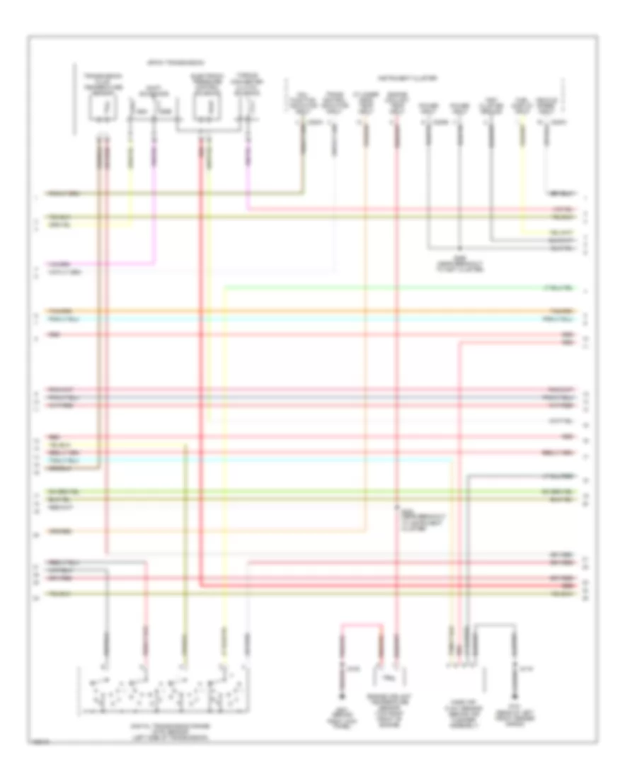
4.6L, Engine Performance Wiring Diagrams (2 of 4) for Ford Crown Victoria Police Interceptor 2002
 https://portal-diagnostov.com/license.html
Automotive Electricians Portal FZCO
Automotive Electricians Portal FZCO
https://portal-diagnostov.com/license.html
https://portal-diagnostov.com/license.html
Automotive Electricians Portal FZCO
Automotive Electricians Portal FZCOList of elements for 4.6L, Engine Performance Wiring Diagrams (2 of 4) for Ford Crown Victoria Police Interceptor 2002:
- (near breakout to right heated oxygen sensor 11)
- (speedometer/ odometer) vehicle speed input
- 4r70w transmission
- Analog
- C220a
- C220b
- C220c
- Cylinder head temp input
- Differential pressure feedback egr sensor (right side of intake manifold)
- Digital
- Digital transmission range (dtr) sensor (left side of transmission)
- Electronic pressure control solenoid
- Engine coolant temp input
- Engine coolant temperature sender (top right front of engine)
- Fuel flow rate input
- G101 (rear of left front fender apron)
- G201 (behind right kick panel)
- Instrument cluster
- Malfunction indicator input
- Mass air- flow sensor (behind air cleaner assembly)
- R n
- Red
- S105
- S119
- S126
- S150
- S222 (near breakout to inst cluster)
- Shift solenoids
- Ssa
- Ssb
- Throttle position sensor (left side of throttle body)
- Torque converter clutch solenoid
- Transmission control indicator input
- Transmission fluid temperature sensor
- Vapor management valve (rear center of engine compt)
4.6L, Engine Performance Wiring Diagrams (3 of 4) for Ford Crown Victoria Police Interceptor 2002
 https://portal-diagnostov.com/license.html
Automotive Electricians Portal FZCO
Automotive Electricians Portal FZCO
https://portal-diagnostov.com/license.html
https://portal-diagnostov.com/license.html
Automotive Electricians Portal FZCO
Automotive Electricians Portal FZCOList of elements for 4.6L, Engine Performance Wiring Diagrams (3 of 4) for Ford Crown Victoria Police Interceptor 2002:
- (center rear of trunk) g400
- (in trunk, on left support) inertia fuel shutoff switch
- (near breakout to 12-pin conn at left rear of engine compt)
- (near breakout to 8-pin conn left rear of engine)
- (near left rear of engine compt)
- (near left rear of engine compt) s148
- (top of brake pedal support) brake pedal position switch
- Air conditioning (a/c clutch relay)
- Battery junction box (right front of engine compt)
- Camshaft position sensor (left front of engine, below left ignition coil)
- Central junction box (below dash, left of steering column)
- Cooling fans (fan high low relays)
- Cylinder head temperature sensor (top left front of engine)
- Fuel pump relay
- Fuel pump/ fuel gauge sender
- Fuel tank assembly
- Fuel tank pressure sensor (on upper fuel tank assembly)
- Fuse 15a
- Fuse 20a
- Hot at all times
- Left heated oxygen sensor 21 (lower left rear of engine, in exhaust manifold)
- Left heated oxygen sensor 22 (in exhaust, rear of catalyst)
- Nca
- Output shaft speed sensor (left rear side of transmission)
- Red
- Red/pnk
- Relay center (left side of engine compt)
- Right heated oxygen sensor 11 (lower right rear of engine, in exhaust manifold)
- Right heated oxygen sensor 12 (in exhaust, rear of catalyst)
- S115 (near breakout to 16-pin conn at left rear of engine compt)
- S123
- S125
- S129
- S130
- S132
- S147
- S265
- S402
4.6L, Engine Performance Wiring Diagrams (4 of 4) for Ford Crown Victoria Police Interceptor 2002
 https://portal-diagnostov.com/license.html
Automotive Electricians Portal FZCO
Automotive Electricians Portal FZCO
https://portal-diagnostov.com/license.html
https://portal-diagnostov.com/license.html
Automotive Electricians Portal FZCO
Automotive Electricians Portal FZCOList of elements for 4.6L, Engine Performance Wiring Diagrams (4 of 4) for Ford Crown Victoria Police Interceptor 2002:
- (behind right side of dash) air suspension module
- (behind right side of dash) electronic variable orifice steering module
- (behind right side of dash) warning buzzer/ chime module
- (left rear corner of engine compt) speed control actuator
- (left rear side of transmission) vehicle speed sensor
- (near breakout to 42-pin conn at left rear of eng compt)
- (near ground at center rear of engine)
- (rear of vehicle, below left side of trunk) evap canister vent valve
- A/c cutout sw
- A/c system (a/c clutch sw)
- A/c system (a/c cutout rly)
- A/c wot cutout
- Batt
- Brake on/off
- C122
- C2131b
- C2156
- C2230
- Cam pos in
- Can vent sol
- Cht sensor
- Coil 2
- Coil 7
- Coil 8
- Dpfe sens
- Epc sol
- Evap purge vlve
- Fuel inj 1
- Fuel inj 2
- Fuel inj 3
- Fuel inj 4
- Fuel inj 5
- Fuel inj 6
- Fuel inj 7
- Fuel inj 8
- Fuel injectors
- Fuel press
- Fuel pump ctrl
- G101 (rear of left front fender apron)
- G201 (behind right kick panel)
- Heater ctrl
- Iac sol
- Idle air control valve (left side of intake manifold)
- L ho2s
- Lft ho2s 21
- Lft ho2s 22
- Maf sens in
- Oss (+)
- Power
- Power gnd
- Powertrain control module (pcm) (in engine compt, on left side of firewall)
- Pwr gnd
- R ho2s
- Red
- Red/pnk
- Ref volt
- Rt ho2s 11
- S105
- S109 (near breakout to 12-pin conn at left rear of engine compt)
- S119
- S131
- S143
- S247 (near breakout to front control unit)
- Sig rtn
- Tan
- Tan/red
- Tcc sol
- Tp sens in
- Tr3
- Vss (+)
- Vss (-)
- W/ air suspension & evo steering
- W/ evo steering only
EXTERIOR LIGHTS
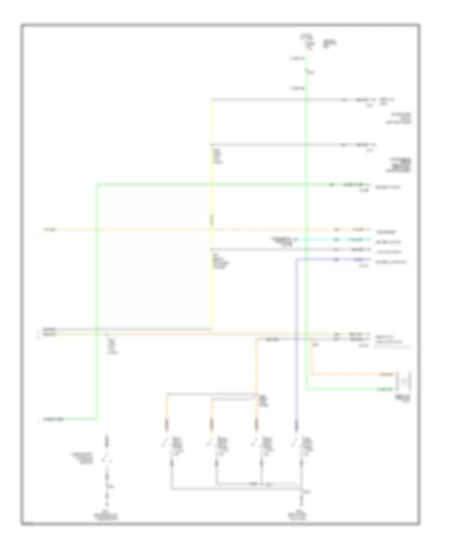
Accessory Lamps Wiring Diagram, Police Option for Ford Crown Victoria Police Interceptor 2002
 https://portal-diagnostov.com/license.html
Automotive Electricians Portal FZCO
Automotive Electricians Portal FZCO
https://portal-diagnostov.com/license.html
https://portal-diagnostov.com/license.html
Automotive Electricians Portal FZCO
Automotive Electricians Portal FZCOList of elements for Accessory Lamps Wiring Diagram, Police Option for Ford Crown Victoria Police Interceptor 2002:
- (center of package tray) s422
- (left side rear of luggage compt) s419
- (right side rear of luggage compt) s416
- C2145b
- Central junction box (below dash, left of steering column)
- Emergency flasher relay 1
- Emergency flasher relay 2
- Emergency flasher relay block (in left rear of trunk)
- Exterior lights circuit
- Fuse 20a
- G200 (behind right kick panel)
- G400 (center rear of luggage compartment)
- G400 (center rear of luggage compt)
- Harn, near rear flasher)
- Hot at all times
- Interior lights system
- Left package tray lamp connection
- Left police flasher lamp
- Left rear park/ stop/turn lamp 1
- Left rear park/ stop/turn lamp 2
- Left spotlight
- Lighting control module (behind left side of dash)
- Luggage compartment lid release solenoid
- Position switch)
- Rear flasher (center rear of trunk)
- Rear flasher relay (center rear of trunk)
- Right package tray lamp connection
- Right police flasher lamp
- Right rear park/ stop/ turn lamp 2
- Right rear park/ stop/turn lamp 1
- Right spotlight
- S227
- S228
- S400
- S401
- S402
- S403
- S418 (left side rear of luggage compt)
- S426
- S449 (front left side of luggage compt)
- Trunk, tailgate, fuel doors system
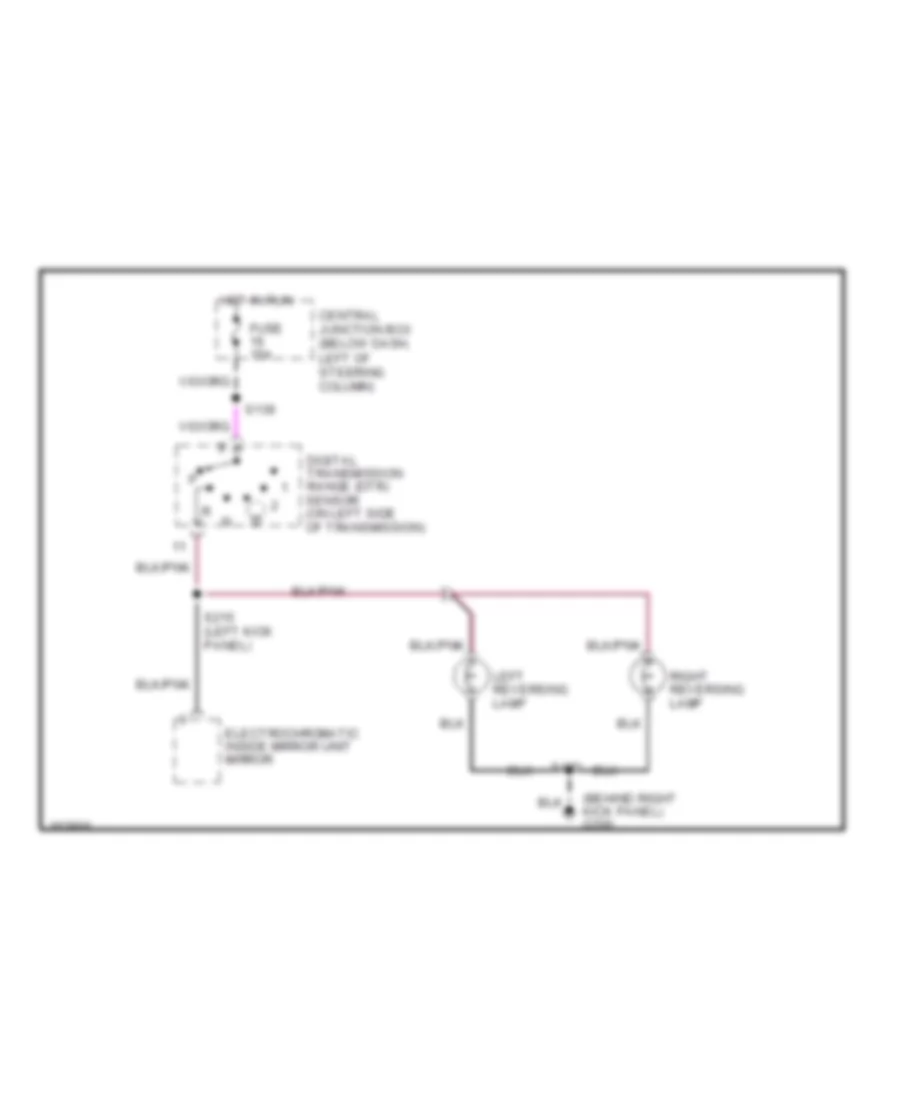
Back-up Lamps Wiring Diagram for Ford Crown Victoria Police Interceptor 2002
 https://portal-diagnostov.com/license.html
Automotive Electricians Portal FZCO
Automotive Electricians Portal FZCO
https://portal-diagnostov.com/license.html
https://portal-diagnostov.com/license.html
Automotive Electricians Portal FZCO
Automotive Electricians Portal FZCOList of elements for Back-up Lamps Wiring Diagram for Ford Crown Victoria Police Interceptor 2002:
- (behind right kick panel) g200
- Central junction box (below dash, left of steering column)
- Digital transmission range (dtr) sensor (on left side of transmission)
- Electrochromatic inside mirror unit mirror
- Fuse 15a
- Hot in run
- Left reversing lamp
- Right reversing lamp
- S139
- S215 (left kick panel)
- S420
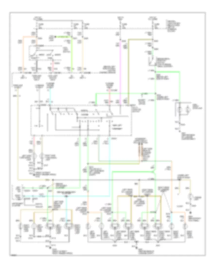
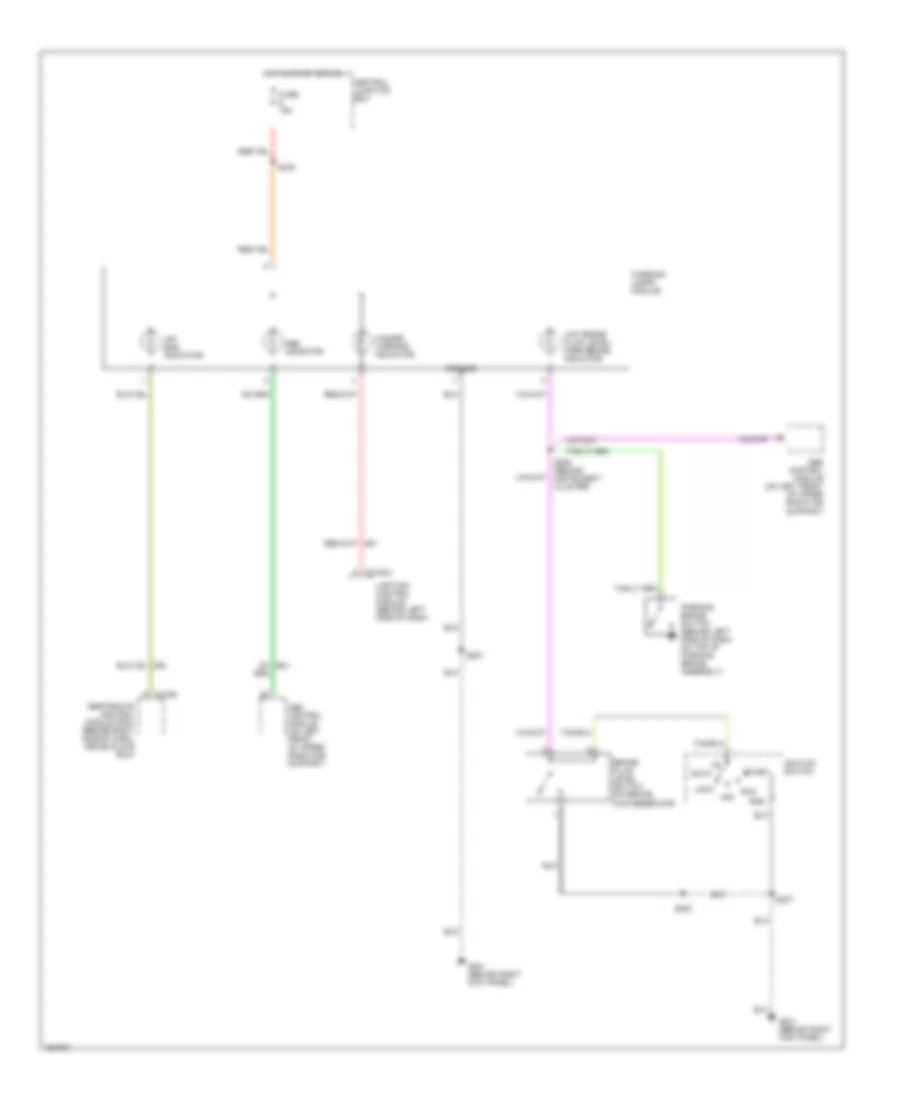
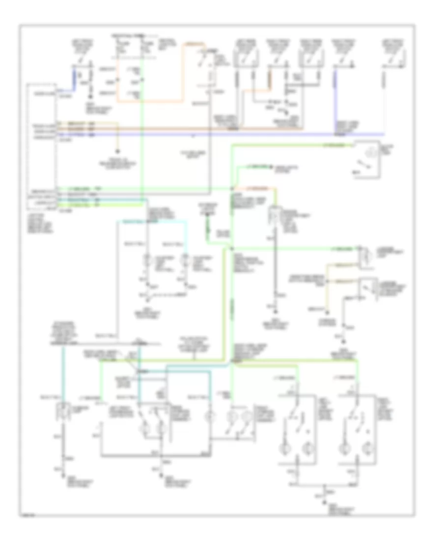
Exterior Lamps Wiring Diagram for Ford Crown Victoria Police Interceptor 2002
 https://portal-diagnostov.com/license.html
Automotive Electricians Portal FZCO
Automotive Electricians Portal FZCO
https://portal-diagnostov.com/license.html
https://portal-diagnostov.com/license.html
Automotive Electricians Portal FZCO
Automotive Electricians Portal FZCOList of elements for Exterior Lamps Wiring Diagram for Ford Crown Victoria Police Interceptor 2002:
- (behind instrument cluster)
- (behind left side of dash) lighting control module
- (front of right front fender apron) g102
- (left rear of luggage compt) s413
- (left rear of luggage compt) s442
- (left side front of engine compt) s120
- (left side of luggage compt) s440
- (left side rear of luggage compt) (police only) s419
- (right rear of luggage
- (right rear of luggage compt)
- (under left side of dash) s242
- Accessory lamps circuit (police option)
- Analog
- B+ vbat 1
- B+ vbat 2
- B+ vbat 3
- Brake pedal position switch (top of brake pedal support)
- C202a
- C202b
- C205a
- C2145b
- C2145c
- C220c
- C2220a
- C2220b
- Central junction box (below dash, left of steering column)
- Clock
- Compt) s414
- Digital
- Except police option
- Flasher power input
- Flasher power output
- Fuse 15a
- Fuse 20a
- G102 (front of right front fender apron)
- G200 (behind right kick panel)
- G400 (center rear of luggage compt)
- G401 (center rear of luggage compartment)
- Hazard
- Head
- High mount stoplamp
- Hot at all times
- Hot in run
- Instrument cluster
- Left front park/ turn lamp
- Left front side lamp
- Left rear park/ stop/ turn lamp 1
- Left rear turn lamp 1
- Left rear turn lamp 2
- Left side turn signal lamp
- Left turn ind
- License lamp
- Lo beams output
- Main light switch
- Main light switch input
- Multi- function switch
- Normal
- Off
- Park
- Parklamp output
- Parklamp switch input
- Right front park/ turn lamp
- Right front side lamp
- Right rear turn lamp 1
- Right rear turn lamp 2
- Right side turn signal lamp
- Right turn ind
- S107
- S108
- S112
- S113
- S226
- S227
- S243 (under left side of dash)
- S244
- S257
- S258 (behind left side of dash)
- S262
- S263
- S265
- S285
- S400
- S401
- S402
- S408
- S409 (left rear of luggage compt)
- S416
- S418 (police only) (left side rear of luggage compt)
- S420
- S422
- Taxi roof lamp
- Turn lamp 1
- Turn lamp 2
- Turn left
- Turn right
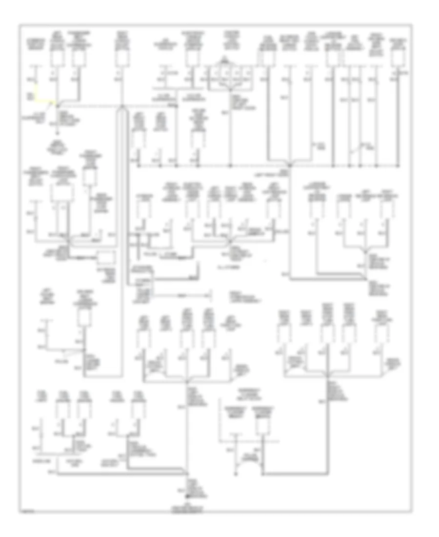
GROUND DISTRIBUTION
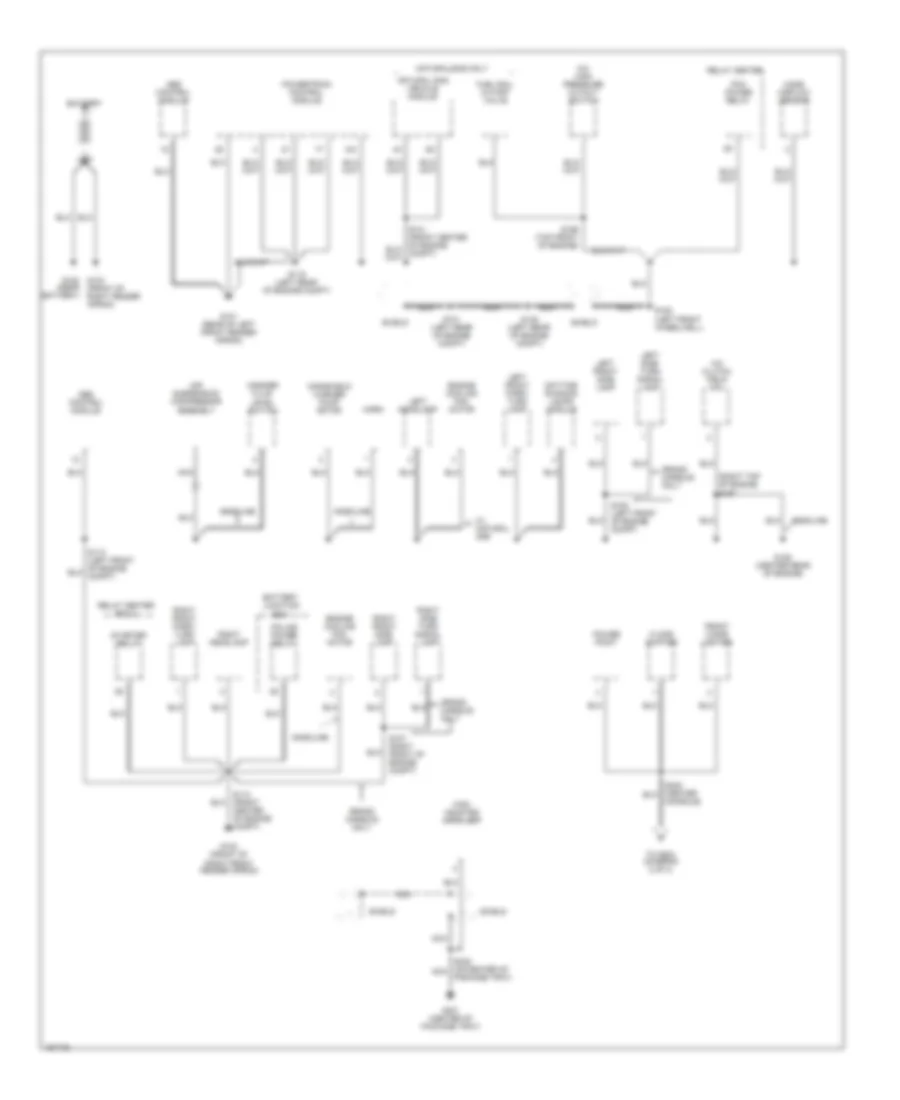
Ground Distribution Wiring Diagram (1 of 3) for Ford Crown Victoria Police Interceptor 2002
 https://portal-diagnostov.com/license.html
Automotive Electricians Portal FZCO
Automotive Electricians Portal FZCO
https://portal-diagnostov.com/license.html
https://portal-diagnostov.com/license.html
Automotive Electricians Portal FZCO
Automotive Electricians Portal FZCOList of elements for Ground Distribution Wiring Diagram (1 of 3) for Ford Crown Victoria Police Interceptor 2002:
- (near battery)
- (right top of engine s157
- A/c clutch field coil
- A/c high pressure cutout switch
- Abs control module
- Air suspension compressor assembly
- Battery
- Battery junction box
- Console)
- Daytime running lamps module
- Engine cooling fan motor
- Floor shifter
- Front cigar lighter
- Fuel rail cutoff valve
- G100 g103 (front of right fender apron)
- G101 (rear of left front fender apron)
- G102 (front of right front fender apron)
- G106 (center rear of engine)
- G401 (center of package tray)
- Gasoline
- Grand marquis only
- High mounted stoplamp
- Horn
- Left front park/ turn lamp
- Left front side lamp
- Left headlamp
- Left side turn signal lamp
- Mass airflow sensor
- Natural gas only
- Natural gas vehicle module
- Nca
- Package tray)
- Pcm power relay
- Police power relay
- Power point
- Powertrain control module
- Relay center
- Relay center box 2
- Right front park/ turn lamp
- Right front side lamp
- Right headlamp
- Right side turn signal lamp
- S101 (left rear of engine compt)
- S107 (right front of engine compt)
- S108 (left front of engine compt)
- S113 (front center of engine conpt)
- S119 (left rear of engine compt)
- S145 (left rear of engine compt)
- S152 (left front wheelwell)
- S156 (top front of engine)
- S422 (on center of nca
- Shield
- Starter relay
- To s204 (diagram 2 of 3)
- W/ natural gas
- Washer fluid level switch
- Windshield washer pump motor
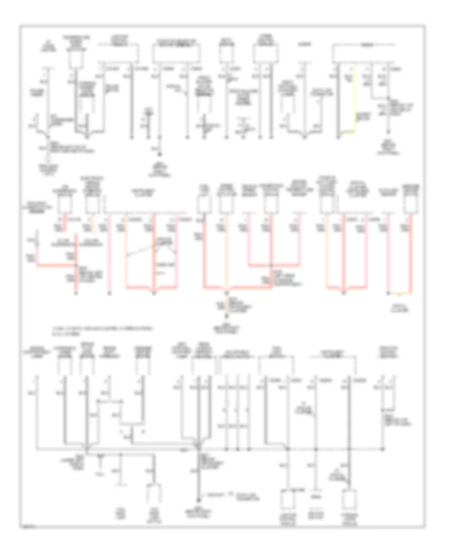
Ground Distribution Wiring Diagram (2 of 3) for Ford Crown Victoria Police Interceptor 2002
 https://portal-diagnostov.com/license.html
Automotive Electricians Portal FZCO
Automotive Electricians Portal FZCO
https://portal-diagnostov.com/license.html
https://portal-diagnostov.com/license.html
Automotive Electricians Portal FZCO
Automotive Electricians Portal FZCOList of elements for Ground Distribution Wiring Diagram (2 of 3) for Ford Crown Victoria Police Interceptor 2002:
- (digital cluster) instrument cluster
- Adjustable pedal switch
- Air suspension module
- All others b
- Analog cluster
- Autolamp sensor
- Brake fluid level switch
- Brake shift interlock
- C205a
- C205b
- C2131b
- C2145b
- C2145c
- C220b
- C220c
- C2220a
- C2220b
- C228a
- C290c
- C294b
- C294d
- Center of dash)
- Clock
- Data link connector
- Digital cluster
- Eatc module
- Electronic varible orifice steering module
- Engine compartment lamp
- Engine coolant temperature sender
- Except police
- From s248 (diagram 1 of 3)
- Front blower motor resistor assembly
- Front blower motor speed control
- Fuel tank unit
- Function selector switch assembly
- G201 (behind right kick panel)
- Gasoline
- I/p cigar lighter
- Ignition switch
- Instrument cluster
- Instrument cluster)
- Left footwell courtesy lamp
- Lighting control module
- Main light switch
- Manual a/c
- Message center switch
- Nca
- Ngv, w/ eatc, analog cluster, w/ premium radio a
- Not used
- Occupant classification sensor
- Passive anti-theft system control module
- Police option
- Power point
- Powertrain control module
- Radio
- Rear window defrost control
- Right center of dash)
- Right footwell courtesy lamp
- S200 (behind left top center of dash)
- S203 (under left side of dash)
- S207 (behind instrument cluster)
- S224 (behind top left of dash)
- Six passenger model
- Speed control actuator
- Taxi
- Taxi roof lamp
- Taxi roof lamp switch
- Temperature blend door actuator
- Traction control switch
- Vehicle speed sensor
- W/ air suspension
- W/ analog cluster
- W/ digital cluster
- W/o air suspension
- Warning buzzer/ chime module
- Warning lamps module
- Windshield wiper motor
- Wiper control module
Ground Distribution Wiring Diagram (3 of 3) for Ford Crown Victoria Police Interceptor 2002
 https://portal-diagnostov.com/license.html
Automotive Electricians Portal FZCO
Automotive Electricians Portal FZCO
https://portal-diagnostov.com/license.html
https://portal-diagnostov.com/license.html
Automotive Electricians Portal FZCO
Automotive Electricians Portal FZCOList of elements for Ground Distribution Wiring Diagram (3 of 3) for Ford Crown Victoria Police Interceptor 2002:
- (center rear of luggage compt)
- 2131b
- 501b
- Air suspension module
- All others
- Crown victoria only
- Driver side exterior rear view mirror
- Driver's seat lumbar compressor motor
- Driver,s door module
- Electro- chromatic inside mirror unit
- Electronic varible orifice steering module
- Emergency flasher relay 1
- Emergency flasher relay 2
- Emergency flasher relay block
- Exterior rear view mirror
- Exterior rear view mirror switch
- Front driver's side seat adjust switch
- Front interior/ map lamps assembly
- Front interior/map lamps assembly
- Front passenger door ajar switch
- Front passenger window/door lock switch
- Front passenger's seat adjust switch
- Fuel door release solenoid
- Fuel tank unit
- Fuel tank valve 1
- Fuel tank valve 2
- Fuel tank valve 3
- Fuel tank valve 4
- G200 (behind right kick panel)
- Gasoline
- Grand marquis only
- Interior lamp
- Key pad switch assembly
- Left front door ajar switch
- Left front map reading lamp switch
- Left power seat switch
- Left rear door ajar switch
- Left rear park/ stop/ turn lamp 1
- Left rear park/ stop/ turn lamp 2
- Left rear park/turn lamp
- Left rear turn lamp 1
- Left rear turn lamp 2
- Left rear window adjust switch
- Left reversing lamp
- Left vanity mirror lamp
- License lamps
- Luggage compartment lid release solenoid
- Luggage compartment lid release switch 1
- Master window/ lock control switch
- Natural gas
- Natural gas only
- One touch window down module
- Other
- Others
- Passenger seat lumbar compression motor
- Police
- Police higher option content
- Police package
- Rear interior/ map lamps assembly
- Rear passenger door ajar switch
- Right rear park/ stop/ turn lamp 1
- Right rear park/ stop/ turn lamp 2
- Right rear park/turn lamp
- Right rear turn lamp 1
- Right rear turn lamp 2
- Right rear window adjust switch
- Right reversing lamp
- Right vanity mirror lamp
- S208 (behind right side of dash)
- S304 (under driver seat)
- S403 (center of vehicle rear end)
- S405 (vehicle underbody, on fuel tank)
- S420 (center of vehicle rear end)
- S428 (on fuel tank)
- S500 (left front door)
- S503 (center of left front door)
- S600 (center of right front door)
- Standard production
- Steering position sensor
- W/ air suspension
- W/ air suspension only
- W/ rke
- W/o air suspension
- W/o rke
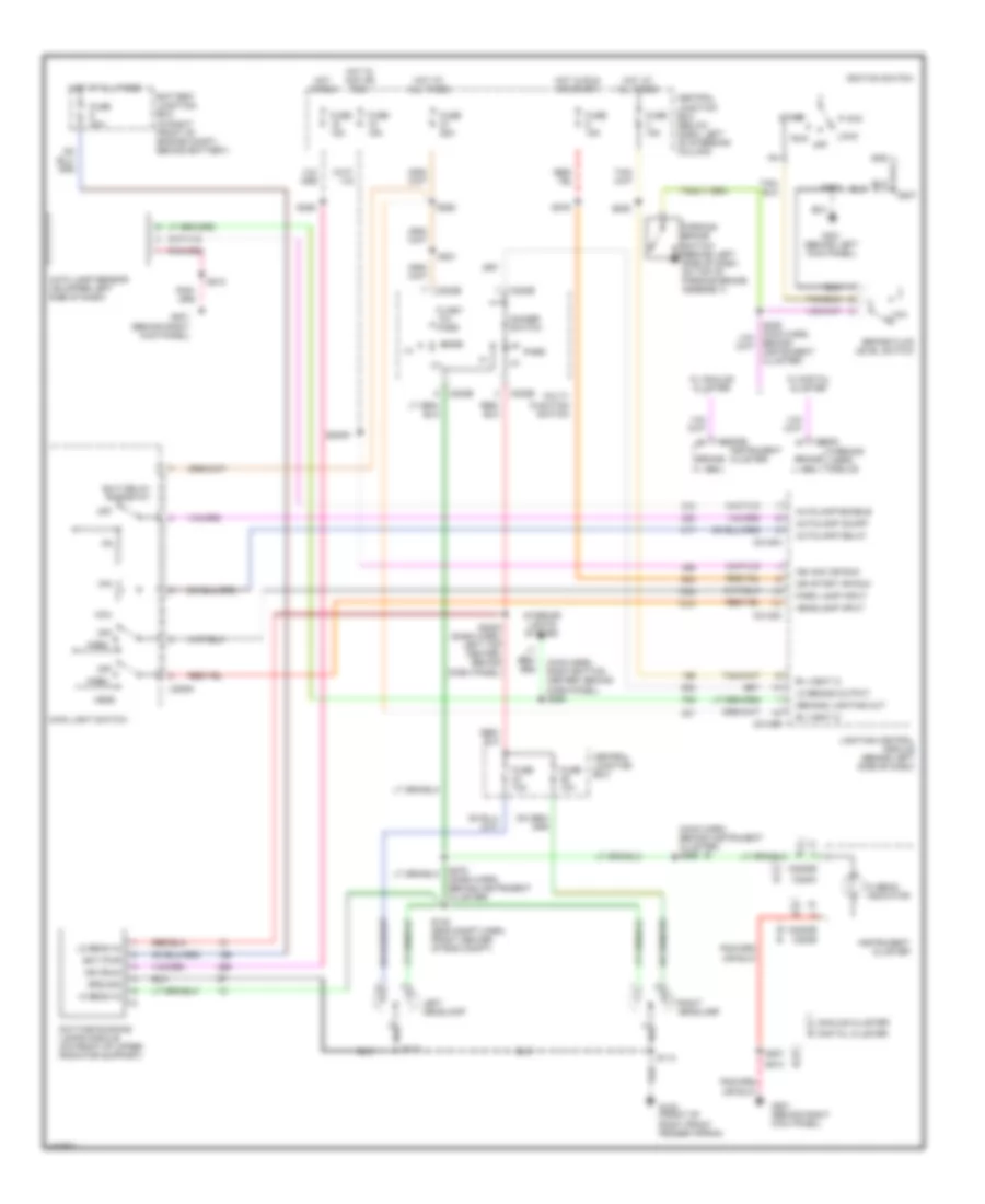
HEADLIGHTS
Headlamps Wiring Diagram, with DRL for Ford Crown Victoria Police Interceptor 2002
 https://portal-diagnostov.com/license.html
Automotive Electricians Portal FZCO
Automotive Electricians Portal FZCO
https://portal-diagnostov.com/license.html
https://portal-diagnostov.com/license.html
Automotive Electricians Portal FZCO
Automotive Electricians Portal FZCOList of elements for Headlamps Wiring Diagram, with DRL for Ford Crown Victoria Police Interceptor 2002:
- (main harn, behind instrument cluster) s269
- (main harn, right bottom center, behind dash panel) s290
- A b
- Acc
- Analog cluster a b digital cluster
- Aut0lamp enable
- Auto lamp sensor (on upper left side of dash)
- Autolamp delay
- Autolamp on/off
- B+ (vbat 2)
- B+ (vbat 3)
- Bat pwr
- Battery junction box (in right front of engine compt, behind battery)
- Behind instrument cluster)
- Brake fluid level switch
- Brake ind
- C202b
- C205a
- C2145a
- C2145b
- C2145c
- C220b
- C220c
- C2220b
- C2222
- Central junction box
- Central junction box (below dash, left of steering column)
- Daytime running lamps module (on front of upper radiator support)
- Demand lighting out
- Dimmer switch
- Exit delay rheostat
- Flash -to- pass
- Fuse 10a
- Fuse 15a
- Fuse 20a
- Fuse 25a
- G102 (front of right front fender apron)
- G201 (behind left kick panel)
- G201 (behind right kick panel)
- Gnd
- Ground
- Head
- Headlamp input
- Hi beam in
- Hi beam indicator
- Hot at all times
- Hot in acc or run
- Hot in run
- Hot in run or start
- Ign (run)
- Ign acc or run
- Ign start or run
- Ignition switch
- Instrument cluster
- Interior lights system
- Left headlamp
- Lighting control module (behind left side of dash)
- Lo beam in
- Lo beams output
- Lock
- Low
- Main light switch
- Max
- Min
- Multi- function switch
- Off
- Park
- Park lamp input
- Parking brake switch (behind left side of dash, on top of parking brake assembly)
- Pass
- Right headlamp
- Run
- S112
- S113
- S138 (eng compt harn, front center of eng compt)
- S2000 (dash harn, left top center, behind dash panel)
- S2009
- S201
- S203
- S207
- S210
- S226
- S262
- S276
- S278 (dash harn, behind instrument cluster)
- S285
- Start
- W/ analog cluster
- W/ digital cluster
- Warning lamps module
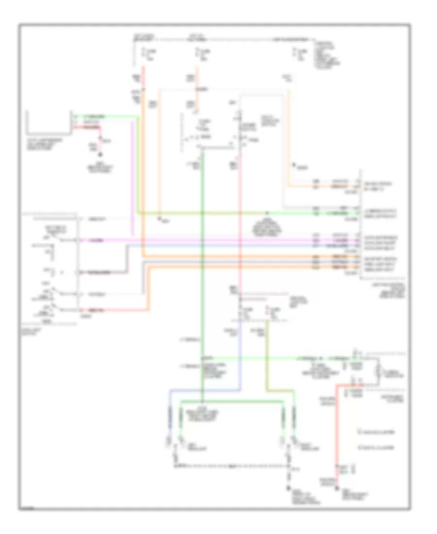
Headlamps Wiring Diagram, without DRL for Ford Crown Victoria Police Interceptor 2002
 https://portal-diagnostov.com/license.html
Automotive Electricians Portal FZCO
Automotive Electricians Portal FZCO
https://portal-diagnostov.com/license.html
https://portal-diagnostov.com/license.html
Automotive Electricians Portal FZCO
Automotive Electricians Portal FZCOList of elements for Headlamps Wiring Diagram, without DRL for Ford Crown Victoria Police Interceptor 2002:
- A b
- Analog cluster a
- Aut0lamp enable
- Auto lamp sensor (on upper left side of dash)
- Autolamp delay
- Autolamp on/off
- B digital cluster
- B+ (vbat 2)
- Behind instrument cluster)
- C205a
- C2145a
- C2145b
- C2145c
- C220b
- C220c
- C2220b
- Central junction box
- Central junction box (below dash, left of steering column)
- Dimmer switch
- Dmnd lghtng out
- Exit delay rheostat
- Flash -to- pass
- Fuse 10a
- Fuse 15a
- Fuse 25a
- G102 (front of right front fender apron)
- G201 (behind right kick panel)
- Head
- Headlamp input
- Hi beam indicator
- Hot at all times
- Hot in acc or run
- Hot in run or start
- Ign acc or run
- Ign start or run
- Instrument cluster
- Left headlamp
- Lighting control module (behind left side of dash)
- Lo beams output
- Main light switch
- Max
- Min
- Multi- function switch
- Off
- Park
- Park lamp input
- Pass
- Right headlamp
- S112
- S113
- S138 (eng compt harn, front center of eng compt)
- S2009
- S201
- S207
- S210
- S262
- S269 (main harn, behind instrument cluster)
- S276
- S278
- S290 (main harn, right bottom center, behind dash panel)
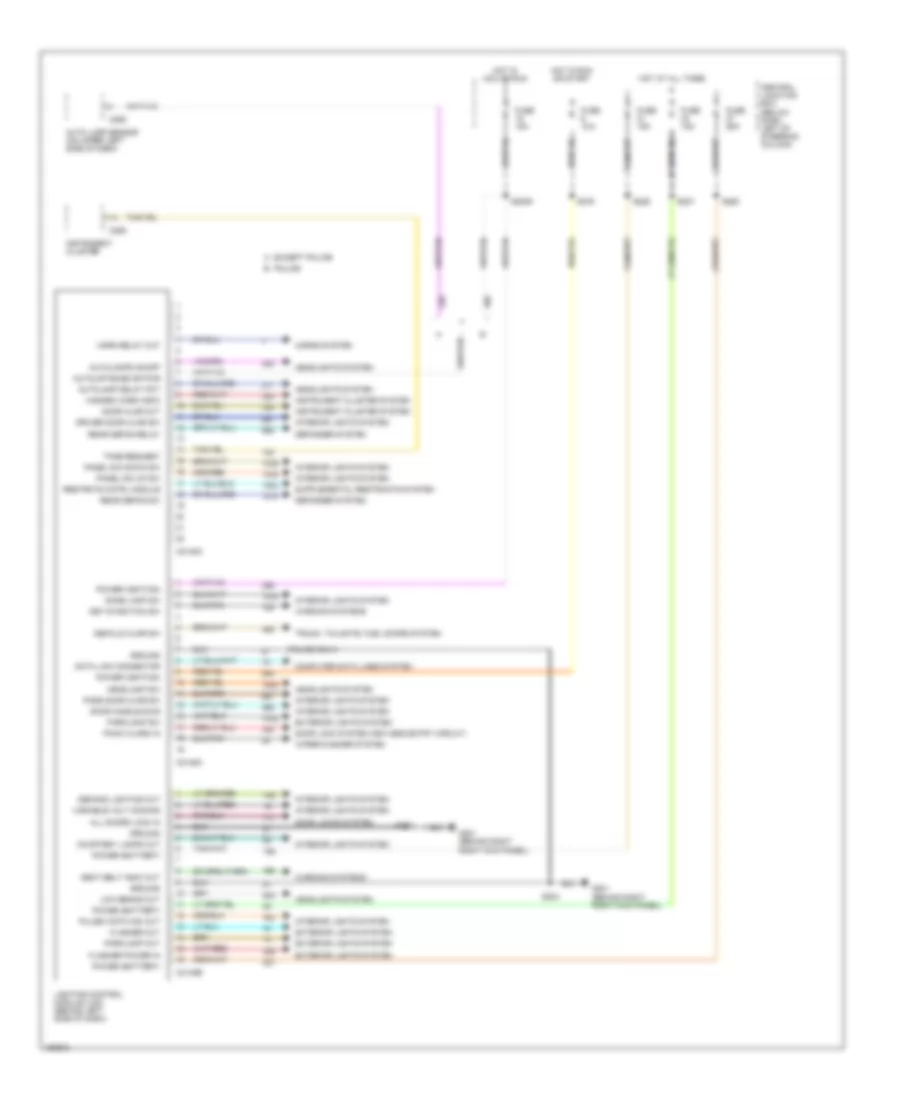
Lighting Control Module Wiring Diagram for Ford Crown Victoria Police Interceptor 2002
 https://portal-diagnostov.com/license.html
Automotive Electricians Portal FZCO
Automotive Electricians Portal FZCO
https://portal-diagnostov.com/license.html
https://portal-diagnostov.com/license.html
Automotive Electricians Portal FZCO
Automotive Electricians Portal FZCOList of elements for Lighting Control Module Wiring Diagram for Ford Crown Victoria Police Interceptor 2002:
- (police only)
- A except police
- All doors lock in
- Auto lamp sensor (on upper left side of dash)
- Autolamp delay pot
- Autolamps on/off
- Autolmp enab or pwr
- B police
- C2145a
- C2145b
- C2145c
- C255
- C286
- Central junction box (below dash, left of steering column)
- Computer data lines system
- Courtesy lamps out
- Data link connector
- Decklid ajar sw
- Defogger system
- Demand lighting out
- Dome lamp sw
- Door ajar out
- Door handle sws
- Door lock system (keyless entry circuit)
- Door locks system
- Driver door ajar sw
- Exterior lights system
- Flasher out
- Flasher power in
- Fuse 15a
- Fuse 25a
- G201 (behind right right kick panel)
- Ground
- Hazard warn indic
- Headlamp sw
- Headlights system
- Horn relay out
- Horns system
- Hot at all times
- Hot in acc or run
- Hot in run or start
- Instrument cluster
- Instrument cluster system
- Interior lights system
- Key-in-ignition sw
- Lighting control module (lcm) (behind left side of dash)
- Low beams out
- Panel dim down sw
- Panel dim up sw
- Panic alarm in
- Parklamp out
- Parklamp sw
- Pass door ajar sw
- Power (battery)
- Power (ignition)
- Pulse width dim out
- Rear defog relay
- Rear defog sw
- Restrnts cntrl module
- S2009
- S204
- S207
- S227
- S262
- S276
- S285
- Seat belt indic out
- Tone request
- Trunk, tailgate, fuel doors system
- Variable volt dimming
- Warning systems
- Wiper/washer system
HORN
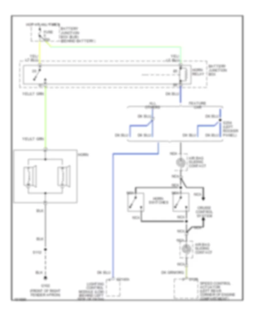
Horn Wiring Diagram for Ford Crown Victoria Police Interceptor 2002
 https://portal-diagnostov.com/license.html
Automotive Electricians Portal FZCO
Automotive Electricians Portal FZCO
https://portal-diagnostov.com/license.html
https://portal-diagnostov.com/license.html
Automotive Electricians Portal FZCO
Automotive Electricians Portal FZCOList of elements for Horn Wiring Diagram for Ford Crown Victoria Police Interceptor 2002:
- (front of right fender apron)
- Air bag sliding contact
- All others
- Battery junction box
- Battery junction box (bjb) (behind battery)
- C122
- C2145a
- Cruise control system
- Feature car
- Fuse 15a
- G102
- Horn
- Horn relay
- Hot at all times
- Lighting control module (lcm) (behind left side of dash)
- Nca
- S112
- S254 (left rocker panel)
- Speed control actuator (left rear corner of engine compartment)
- Switches
INSTRUMENT CLUSTER
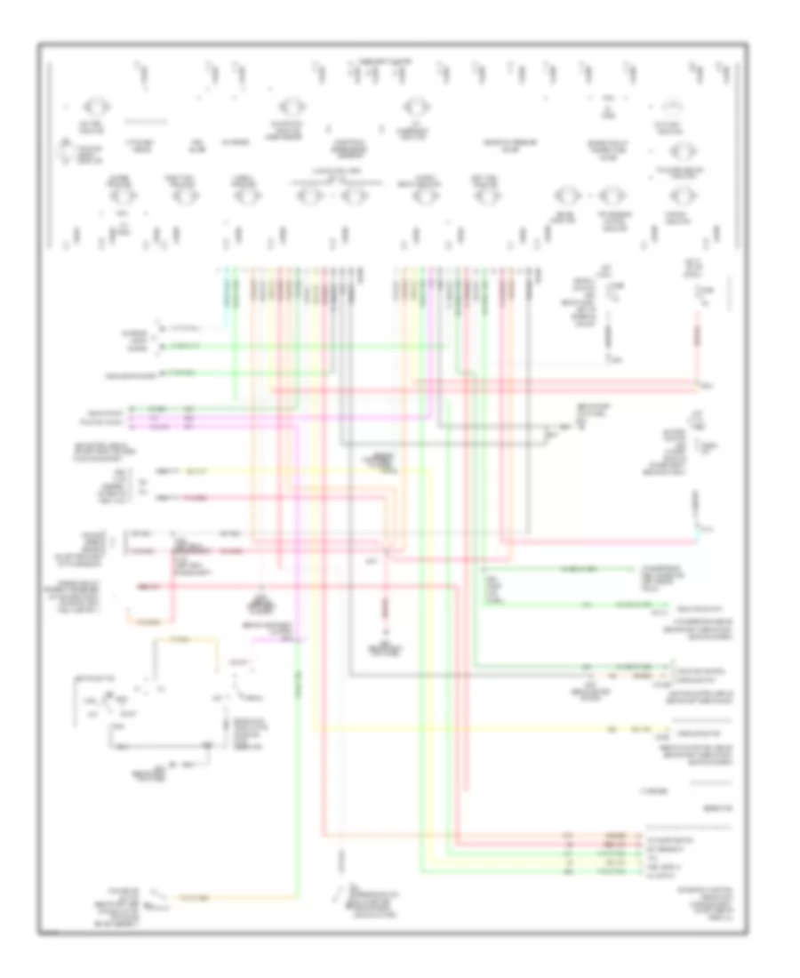
Analog Cluster Wiring Diagram for Ford Crown Victoria Police Interceptor 2002
 https://portal-diagnostov.com/license.html
Automotive Electricians Portal FZCO
Automotive Electricians Portal FZCO
https://portal-diagnostov.com/license.html
https://portal-diagnostov.com/license.html
Automotive Electricians Portal FZCO
Automotive Electricians Portal FZCOList of elements for Analog Cluster Wiring Diagram for Ford Crown Victoria Police Interceptor 2002:
- "air bag"
- "anti-lock"
- "fail-safe cooling"
- "traction
- (behind center
- (behind instrument
- (behind instrument cluster) s202
- (behind left side
- (behind left side of dash)
- (behind right
- (behind right side of dash,
- (below dash,
- (check engine)
- (in engine compt,
- (in right
- (left rear
- (left side of
- (on brake
- (on left front of upper
- (on left rear side
- (on lower left
- (on rear of
- (on top right front
- (qty. 6)
- (right
- 10a
- 15a
- 30a
- Above glove box)
- Above oil filter)
- Abs control module
- Acc
- Air
- Air suspension
- Air suspension module
- Airbag indicator
- Anti-slosh
- Assembly
- Assist"
- At all
- Battery
- Behind battery)
- Belts indicator
- Box
- Brake
- Brake assembly)
- Brake fluid
- C2131a
- C2145b
- C2220a
- C2220b
- C310b
- Central
- Charge
- Cluster)
- Column)
- Control
- Dimming output
- Ect sensor in
- Electronic
- Engine compt)
- Engine compt,
- Engine coolant
- Engine oil pressure
- Exterior
- Fail-safe cooling
- Fasten
- Firewall)
- Fluid
- Front of
- Fuel
- Fuel injector 1)
- Fuel level in
- Fuel tank)
- Fuse
- Fuse 8
- G201
- G201 (behind right kick panel)
- Gauge
- Generator
- Gnd
- Guage
- Headlights system
- Hi beam
- Hot
- Hot in
- Ignition switch
- Illumination lamps
- In run
- Indicator
- Indicator control
- Indicator out
- Indicator output
- Instrument cluster
- Junction
- Kick
- Kick panel)
- Left of
- Left turn
- Level switch
- Lighting control module
- Lights
- Lock
- Low
- Low fuel
- Malfunction
- Mil output
- Module
- Module (pcm)
- Nca
- Normal
- Odometer
- Of dash)
- Of dash, on top
- Of engine, near
- Of parking
- Of transmission)
- Off
- Ohms
- Oil
- On left side of
- Or run
- Panel)
- Park brake
- Powertrain control
- Pressure switch
- Radiator support)
- Reservoir)
- Restraints control module
- Right turn
- Run
- S105
- S109 (left rear engine compt)
- S144
- S207
- S209
- S210
- S222 (behind instrument cluster)
- S231
- S234
- S276
- S287
- Sensor
- Side of engine,
- Speed
- Speedometer/
- Start
- Steering
- Suspension
- Switch
- System
- Tank
- Tcil
- Temperature
- Temperature sender
- Test connector
- Times
- Traction ind out
- Transmission
- Trunk)
- Vehicle
- Voltmeter
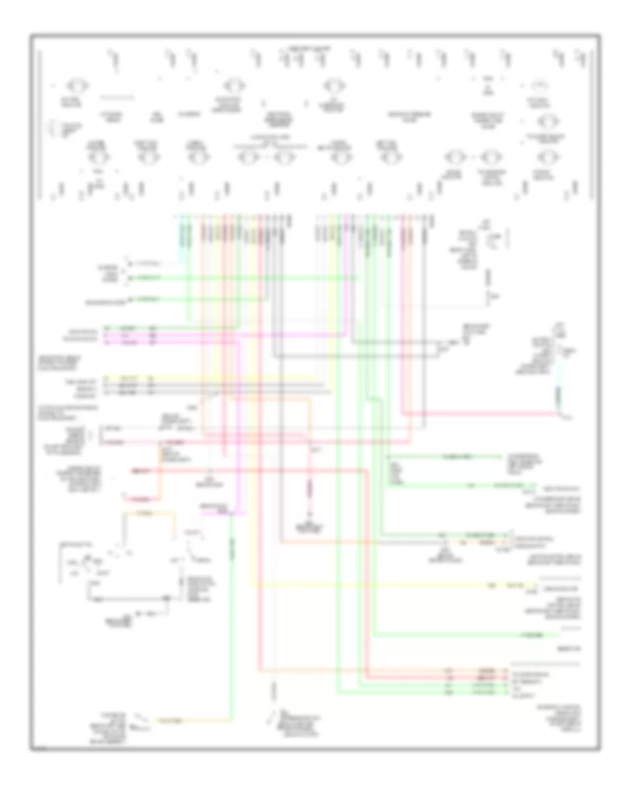
Analog Cluster Wiring Diagram, with Natural Gas for Ford Crown Victoria Police Interceptor 2002
 https://portal-diagnostov.com/license.html
Automotive Electricians Portal FZCO
Automotive Electricians Portal FZCO
https://portal-diagnostov.com/license.html
https://portal-diagnostov.com/license.html
Automotive Electricians Portal FZCO
Automotive Electricians Portal FZCOList of elements for Analog Cluster Wiring Diagram, with Natural Gas for Ford Crown Victoria Police Interceptor 2002:
- "air bag"
- "anti-lock"
- "fail-safe cooling"
- "traction
- (behind
- (behind dash)
- (behind left side
- (behind left side of dash)
- (behind right
- (behind right side of dash,
- (below dash,
- (check engine)
- (in engine compt,
- (in right
- (left side of
- (on brake
- (on front of
- (on front of upper
- (on left rear side
- (on lower left
- (on top right front
- (qty. 6)
- (rear of
- (right
- 10a
- 30a
- Above glove box)
- Above oil filter)
- Abs control module
- Acc
- Air
- Air suspension
- Air suspension module
- Airbag indicator
- Anti-slosh
- Assist"
- At all
- Battery
- Behind battery)
- Belts indicator
- Box
- Brake
- Brake assembly)
- Brake fluid
- C2131a
- C2145b
- C2220a
- C2220b
- C310b
- Center of dash)
- Central
- Charge
- Column)
- Control
- Control module
- Dimming output
- Ect sensor in
- Electronic
- Engine compt)
- Engine compt,
- Engine coolant
- Engine oil pressure
- Exterior
- Fail-safe cooling
- Fasten
- Firewall)
- Fluid
- Front of
- Fuel
- Fuel injector 1)
- Fuel level out
- Fuse
- Fuse 8
- G201
- G201 (behind right kick panel)
- Gauge
- Generator
- Gnd
- Ground in
- Headlights system
- Hi beam
- Hot
- Ignition switch
- Illumination lamps
- In run
- Ind
- Indicator
- Indicator control
- Indicator out
- Indicator output
- Instrument cluster
- Junction
- Kick
- Kick panel)
- Left of
- Left turn
- Level switch
- Lighting control module
- Lights
- Lock
- Low
- Low fuel
- Malfunction
- Mil output
- Module
- Module (pcm)
- Natural gas vehicle module
- Normal
- Odometer
- Of dash, on top
- Of engine, near
- Of parking
- Of transmission)
- Off
- Ohms
- Oil
- On left side of
- Panel)
- Park brake
- Power out
- Powertrain control
- Pressure switch
- Radiator support)
- Reservoir)
- Restraints
- Right turn
- Run
- S105
- S109
- S144
- S207
- S209
- S210
- S222
- S231
- S234
- S287
- S299
- Sensor
- Side of engine,
- Speed
- Speedometer/
- Start
- Steering
- Suspension
- Switch
- System
- Tcil
- Temperature
- Temperature sender
- Test connector
- Times
- Traction ind out
- Transmission
- Trunk)
- Vehicle
- Voltmeter
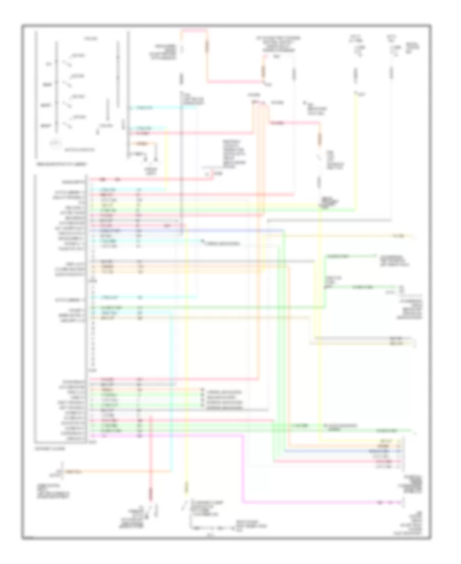
Electronic Cluster Wiring Diagram (1 of 2) for Ford Crown Victoria Police Interceptor 2002
 https://portal-diagnostov.com/license.html
Automotive Electricians Portal FZCO
Automotive Electricians Portal FZCO
https://portal-diagnostov.com/license.html
https://portal-diagnostov.com/license.html
Automotive Electricians Portal FZCO
Automotive Electricians Portal FZCOList of elements for Electronic Cluster Wiring Diagram (1 of 2) for Ford Crown Victoria Police Interceptor 2002:
- (behind center
- (behind instrument cluster) s202
- (behind right
- (front of right
- (in washer
- (left rear corner of
- (left rear of
- (left side of trunk)
- (on left front
- (on left rear side
- (on lower left
- (on rear of
- (on top right front of engine,
- (right kick
- 10a
- 15a
- 17400 ohm
- 2670 ohm
- 7320 ohm
- Above glove box)
- Abs
- Air susp in
- Air suspension
- Airbag ind in
- All times
- Automatic
- Battery power
- Box
- C2131a
- C220a
- C220b
- C220c
- C228b
- Central
- Charge ind in
- Control
- Control (eatc)
- Coolant temp sens in
- Cylinder head temp
- Dim display in
- Door ajar in
- E/m
- Electronic
- Engine compartment)
- Engine compt)
- Engine coolant
- English/metric
- Exterior lights system
- Fasten belts in
- Fluid reservoir)
- Front fender apron)
- Fuel
- Fuel flow rate in
- Fuel level in
- Fuel tank)
- Fuse
- G102
- G201
- Headlights system
- Hi beam in
- Hot at
- Hot in
- Ind
- Instrument cluster
- Interior
- Interior lights system
- Junction
- Kick panel)
- Left turn signal
- Level switch
- Lights
- Low washer fluid in
- Lugg compt ajar
- Malfunction ind
- Message center switch assembly
- Module
- Near fuel injector 1)
- Of dash)
- Of transmission)
- Of upper
- Oil
- Oil pres ind in
- Out
- Output
- Panel)
- Pcm
- Power ground
- Powertrain control module (in engine compt on left side of firewall)
- Pressure
- Prndl illum
- Radiator support)
- Red
- Reset
- Right turn signal
- Run
- S105
- S109
- S112
- S210
- S227
- S231
- S234
- Select
- Sens ground
- Sensor
- Servo
- Side of dash,
- Side of engine, above oil filter)
- Sound tone output
- Speed control
- Speed control in
- Starting/charging
- Switch
- Switch assembly in
- Switch illumination
- Switched power
- System
- Tank
- Temperature
- Temperature sender
- Test connector
- Trans ctrl ind lt
- Unit
- Vehicle speed
- Vehicle speed in +
- Windshield washer
Electronic Cluster Wiring Diagram (2 of 2) for Ford Crown Victoria Police Interceptor 2002
 https://portal-diagnostov.com/license.html
Automotive Electricians Portal FZCO
Automotive Electricians Portal FZCO
https://portal-diagnostov.com/license.html
https://portal-diagnostov.com/license.html
Automotive Electricians Portal FZCO
Automotive Electricians Portal FZCOList of elements for Electronic Cluster Wiring Diagram (2 of 2) for Ford Crown Victoria Police Interceptor 2002:
- (behind
- (behind right
- (center rear of
- (left
- (left front door)
- (right
- Air suspension module (behind right side of dash, above glove box)
- Ajar lamp output
- C2145a
- C2145b
- C2145c
- C216
- C518
- Central junction box
- Cluster)
- Decklid jar
- Door
- Door ajar
- Door ajar indicator (taxi)
- Driver's ajar switch
- Driver's door
- Front
- Fuse 15a
- G200
- G400
- Hot at all times
- Input
- Instrument
- Kick
- Kick panel)
- Latch
- Left
- Lid release
- Luggage compt
- Luggage compt)
- Module
- Panel)
- Pass ajar switch
- Rear
- Right
- S259 (right kick panel)
- S268
- S273
- S277
- S280
- S282
- S403
- S500
- S600
- Seatbelt ind out
- Seatbelt switch
- Solenoid
- Tone request
Electronic Cluster Warning Lamps Wiring Diagram for Ford Crown Victoria Police Interceptor 2002
 https://portal-diagnostov.com/license.html
Automotive Electricians Portal FZCO
Automotive Electricians Portal FZCO
https://portal-diagnostov.com/license.html
https://portal-diagnostov.com/license.html
Automotive Electricians Portal FZCO
Automotive Electricians Portal FZCOList of elements for Electronic Cluster Warning Lamps Wiring Diagram for Ford Crown Victoria Police Interceptor 2002:
- Abs control module (on left front of upper radiator support)
- Abs indicator
- Acc
- Air bag indicator
- Brake fluid level switch (on brake fuid reservoir)
- C2145a
- C310b
- Central junction box
- Fuse 15a
- G201 (behind right kick panel)
- Gnd
- Ground
- Hazard warning indicator
- Hot in start or run
- Ignition switch
- Lighting control module (behind left side of dash)
- Lock
- Low brake fluid level/ park brake indicator
- Off
- Parking brake switch (behind left side of dash, on top of parking brake assembly)
- Restraints control module (rcm) (behind right side of dash, above glove box)
- Run
- S203
- S207
- S209 (behind instrument cluster)
- S276
- Start
- Warning lamps module
INTERIOR LIGHTS
Courtesy Lamps Wiring Diagram for Ford Crown Victoria Police Interceptor 2002
 https://portal-diagnostov.com/license.html
Automotive Electricians Portal FZCO
Automotive Electricians Portal FZCO
https://portal-diagnostov.com/license.html
https://portal-diagnostov.com/license.html
Automotive Electricians Portal FZCO
Automotive Electricians Portal FZCOList of elements for Courtesy Lamps Wiring Diagram for Ford Crown Victoria Police Interceptor 2002:
- (behind right kick panel)
- (body harn, near right "c" pillar) s259
- (body harn, right side of dash) s238
- (main harn, behind right side of dash) s236
- (main harn, near glove box lamp breakout)
- (near park brake switch breakout) s295
- (roof harn, near center of right "c" pillar)
- (roof harn, near front interior/ reading lamp breakout) s900
- All others
- B (+)
- C205a
- C2145a
- C2145b
- C2145c
- Central junction box
- Courtesy lamp, left footwell
- Courtesy lamp, right footwell
- Demand out
- Door ajar
- Engine compartment lamp (ngv & police option)
- Except police option
- Exterior lights system
- Front interior/ map lamp assembly
- Fuse 15a
- Fuse 25a
- G200
- G200 (behind right kick panel)
- G201 (behind right kick panel)
- Glove box lamp
- Handle sw
- Headlights system
- Hot at all times
- Interior lamp
- Lamps out
- Left front door ajar switch
- Left front map/reading lamp switch
- Left rear door ajar switch
- Left vanity lamp (except police option)
- Lighting control module (lcm) (behind left side of dash)
- Luggage compartment lamp
- Luggage compartment lid release solenoid
- Main light switch
- Nca
- Police option
- Police option w/ lower option content interior lamp
- Rear interior/ map lamp assembly
- Right front door ajar switch
- Right rear door ajar switch
- Right vanity lamp (except police option)
- S203
- S204
- S207
- S208
- S216 (near brake pedal position switch breakout)
- S227
- S262
- S403
- S500
- S901
- S902
- Standard production & police w/ lower option content interior lamp
- Switch input
- Trunk ajar
- Trunk lid release solenoid/ ajar switch
- W/o keyless entry
- Warning systems
Instrument Illumination Wiring Diagram for Ford Crown Victoria Police Interceptor 2002
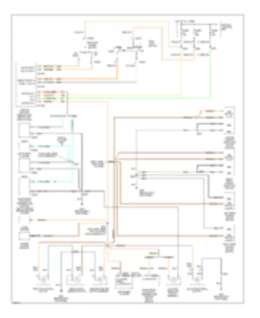 https://portal-diagnostov.com/license.html
Automotive Electricians Portal FZCO
Automotive Electricians Portal FZCO
https://portal-diagnostov.com/license.html
https://portal-diagnostov.com/license.html
Automotive Electricians Portal FZCO
Automotive Electricians Portal FZCOList of elements for Instrument Illumination Wiring Diagram for Ford Crown Victoria Police Interceptor 2002:
- (behind right kick panel)
- (body harn, right side of dash)
- (digital) (analog)
- (main harn, near clock breakout)
- Adjustable pedal switch
- Air bag sliding contact
- B (+)
- C205a
- C205b
- C2145a
- C2145b
- C2145c
- C220b
- C220c c2220b
- C228a
- C228b
- C290c
- Central junction box
- Cluster/ prndl illumination
- Digital cluster only
- Dim dn input
- Dim down
- Dim up
- Dim up input
- Dimming out
- Electronic automatic temperature control (eatc) module
- Electronic automatic temperature control (eatc) module (behind center of dash)
- Floor shifter
- Function selector switch assembly
- Fuse 15a
- Fuse 25a
- G200
- G201 (behind right kick panel)
- Grd
- Head
- Headlamp dimmer switch
- Headlite sw in
- Hot at all times
- Illumination
- Instrument cluster
- Led switch illum
- Left rear window adjust switch
- Lighting control module (lcm) (behind left side of dash)
- Main light switch
- Master window/ door lock/ unlock switch
- Message center switch assembly
- Nca
- Off
- Others
- Park
- Park lt sw in
- Police option
- Radio
- Rear window defrost switch
- Right front window/ door lock switch
- Right rear window adjust switch
- S204
- S207
- S208
- S227
- S233
- S262
- S285
- S287 (main harn, near eatc control module breakout)
- S288
- S503
- S600
- Traction control switch
- W/ eatc
- W/o eatc
POWER DISTRIBUTION
Power Distribution Wiring Diagram (1 of 5) for Ford Crown Victoria Police Interceptor 2002
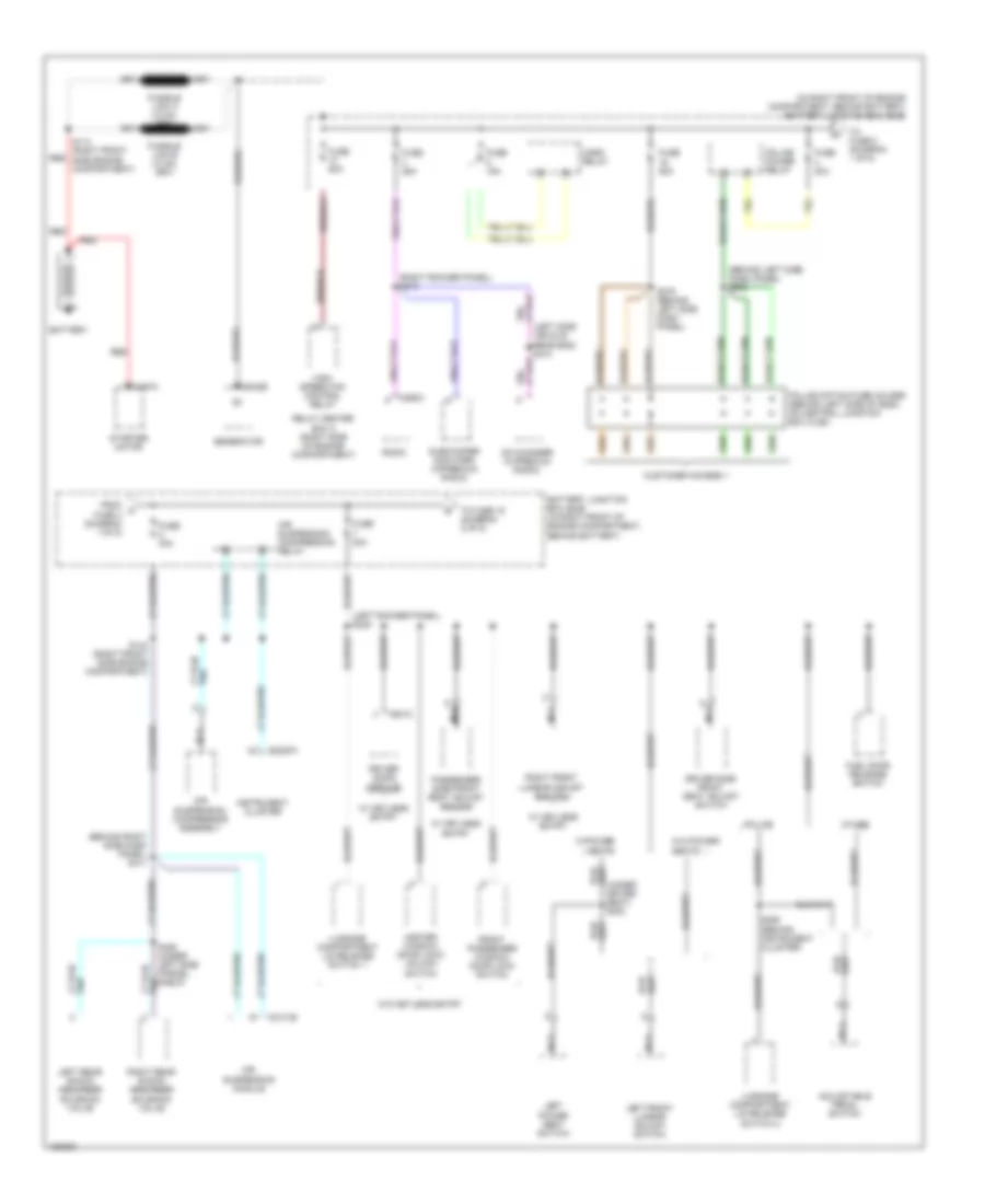 https://portal-diagnostov.com/license.html
Automotive Electricians Portal FZCO
Automotive Electricians Portal FZCO
https://portal-diagnostov.com/license.html
https://portal-diagnostov.com/license.html
Automotive Electricians Portal FZCO
Automotive Electricians Portal FZCOList of elements for Power Distribution Wiring Diagram (1 of 5) for Ford Crown Victoria Police Interceptor 2002:
- (behind left side dash panel) s283
- (behind right side dash panel) s411
- (in right front of engine compartment, behind battery) battery junction box (bjb)
- (left rocker panel) s245
- (right rocker panel) s213
- Adjustable pedal switch
- Air suspension compression relay
- Air suspension compressor assembly
- Air suspension module
- Battery
- Battery junction box (bjb) (in right front of engine compartment, behind battery)
- C102b
- C197a
- C2131b
- C2220a
- C290c
- C501c
- Cd changer (w/premium radio)
- Customer access 1
- Driver door module
- Driver side front seat adjust switch
- From a fuse 4 (diagram 1 of 5)
- Front passenger window/ door lock switch
- Fuel door release switch
- Fuse 15a
- Fuse 20a
- Fuse 25a
- Fuse 30a
- Fuse 50a
- Generator
- High speed fan control relay
- Horn relay
- Instrument cluster
- Left front lumbar adjust switch
- Left power seat switch
- Left rear shock absorber solenoid valve
- Luggage compartment lid release switch 1
- Luggage compartment lid release switch 2
- Master window/ door lock/ unlock switch
- Nca
- Other
- Passenger side front seat adjust switch
- Police
- Police option fuse holder (behind left side of dash, on central junction box (cjb))
- Police power relay
- Radio
- Red
- Relay center box 2 (right side of engine compartment)
- Right front lumbar adjust switch
- Right rear shock absorber solenoid valve
- S114 (right front side engine compartment)
- S144 (right front side engine compartment)
- S250 (behind instrument cluster)
- S275 (behind left side dash panel)
- S406 (under left side parcel shelf)
- Starter motor
- Subwoofer amplifier (w/premium radio)
- To fuse 15 (diagram 2 of 5)
- To fuse 8 (diagram 1 of 5)
- W/ keyless entry
- W/o keyless entry
- W/o power seats
- W/power seats
Power Distribution Wiring Diagram (2 of 5) for Ford Crown Victoria Police Interceptor 2002
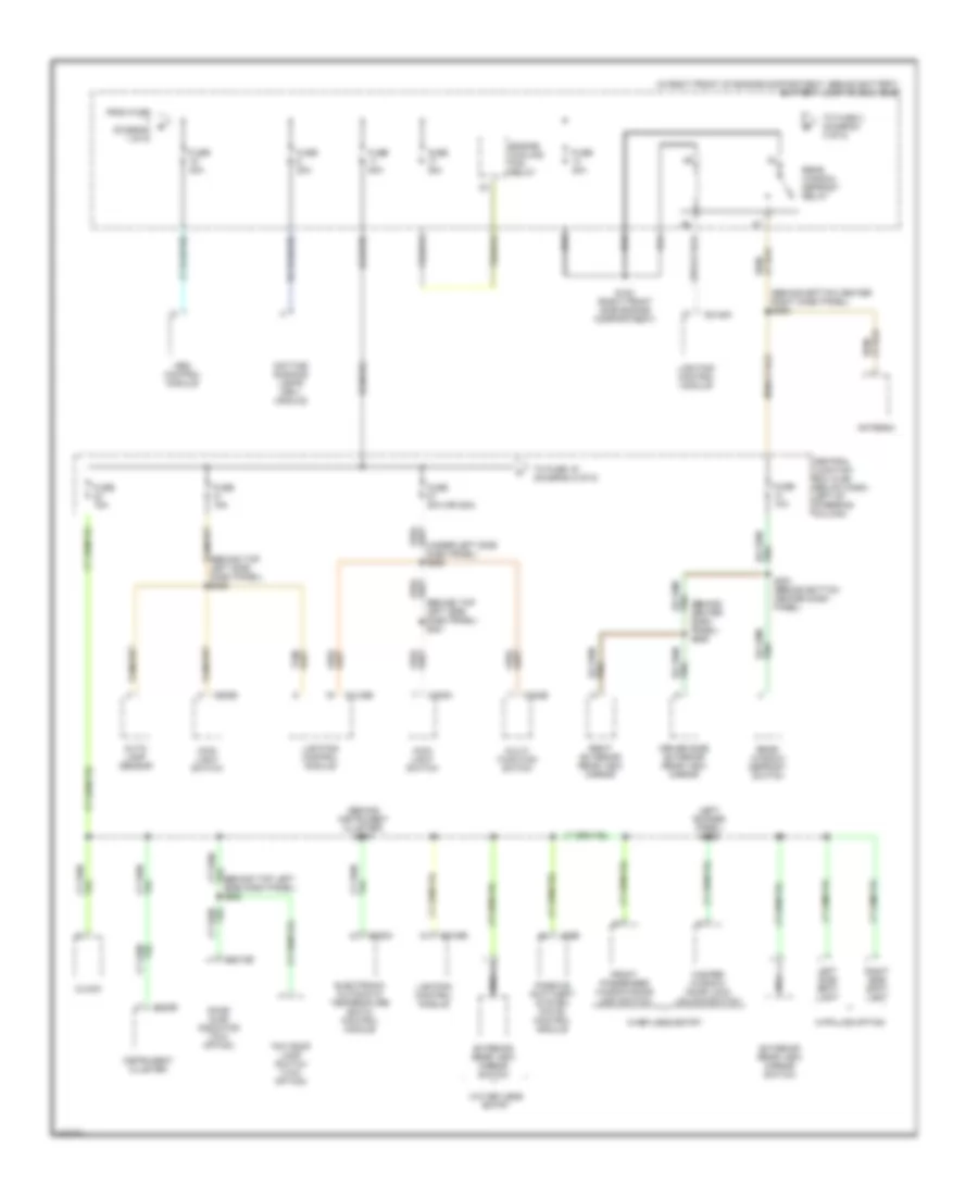 https://portal-diagnostov.com/license.html
Automotive Electricians Portal FZCO
Automotive Electricians Portal FZCO
https://portal-diagnostov.com/license.html
https://portal-diagnostov.com/license.html
Automotive Electricians Portal FZCO
Automotive Electricians Portal FZCOList of elements for Power Distribution Wiring Diagram (2 of 5) for Ford Crown Victoria Police Interceptor 2002:
- (behind bottom center right dash panel) s252
- (behind center dash panel) s256
- (behind instrument cluster) s227
- (behind top left side dash panel) s201
- (behind top left side dash panel) s282
- (behind top left side dash panel) s285
- (in right front of engine compartment, behind battery) battery junction box (bjb)
- (left rocker panel) s228
- (under left side dash panel) s262
- Abs control module
- Antenna
- Auto- lamp sensor
- C202b
- C205a
- C205b
- C2145a
- C2145b
- C220b
- C2212b
- C228a
- C252
- Central junction box (cjb) (below dash, left of steering column)
- Clock
- Daytime running lamps (drl) module
- Door ajar indicator (taxi option)
- Driver side exterior rear view mirror
- Electronic automatic temperature (eatc) control module
- Engine cooling fan relay
- Exterior rear view mirror switch
- From fuse (diagram 1 of 5)
- Front passenger window/door lock switch
- Fuse 10a
- Fuse 15a
- Fuse 20a
- Fuse 20a (or 25a)
- Fuse 30a
- Fuse 40a
- Fuse 50a
- Instrument cluster
- Left side spot light
- Lighting control module
- Main light switch
- Master window/ door lock unlock switch
- Multi- function switch
- Nca
- Passive anti-theft system (pats) control module
- Rear window defrost relay
- Rear window defrost switch
- Right exterior rear view mirror
- Right side spot light
- S153 (right front side engine compartment)
- S251 (behind bottom center dash panel)
- Taxi roof lamp switch (taxi option)
- To fuse 19 (diagram 5 of 5)
- To fuse 2 (diagram 3 of 5)
- W/keyless entry
- W/o keyless entry
- W/police option
Power Distribution Wiring Diagram (3 of 5) for Ford Crown Victoria Police Interceptor 2002
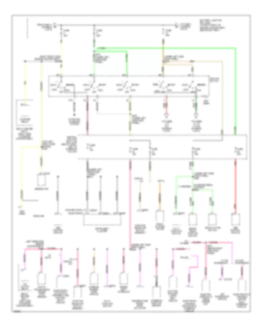 https://portal-diagnostov.com/license.html
Automotive Electricians Portal FZCO
Automotive Electricians Portal FZCO
https://portal-diagnostov.com/license.html
https://portal-diagnostov.com/license.html
Automotive Electricians Portal FZCO
Automotive Electricians Portal FZCOList of elements for Power Distribution Wiring Diagram (3 of 5) for Ford Crown Victoria Police Interceptor 2002:
- (conventional)
- (electronic)
- (left rear side engine compartment) s139
- (not used)
- (on brake pedal support) s265
- (right front side engine compartment) s127
- (top left front side engine) s106
- (under left side dash panel) s219
- (under left side dash panel) s226
- (under left side dash panel) s231
- (under left side dash panel) s263
- A/c clutch relay
- Abs control module
- Acc
- Air suspension module
- All others
- Battery junction box (bjb) (in right front of engine compartment, behind battery)
- Brake pedal position switch
- Brake shift interlock
- C102a
- C202a
- C2131b
- C220b
- C220c
- C2220a
- C228a
- C294c
- Central junction box (cjb) (below dash, left of steering column)
- Daytime running lamps (drl) module
- Deactivator switch
- Digital transmission range (dtr) sensor
- Eatc
- Electro- chromatic inside mirror unit
- Electromatic variable orifice (evo) steering module
- Electronic automatic temperature control (eatc) module
- Electronic variable orifice (evo) steering module
- From fuse 14 (diagram 2 of 5)
- Front blower motor
- Function selector switch assembly
- Fuse 10a
- Fuse 15a
- Fuse 20a
- Fuse 30a
- Fuse 50a
- Gasoline
- Generator
- Ignition switch
- Instrument cluster
- Lock
- Manual a/c
- Multi- function switch
- Nca
- Off
- Police
- Red
- Relay center box 1 (left side of engine compartment)
- Relay center box 2 (right side of engine compartment)
- Run
- S270 (under left side dash panel)
- S274 (behind right side dash panel)
- Start
- Starter relay
- Starting/ charging system
- Steering position sensor
- Temperature blend door actuator
- To fuse 1 (diagram 5 of 5)
- To fuses 13, 15, 17 & 28 (diagram 4 of 5)
- To fuses 4, 6 & 8 (diagram 4 of 5)
- W/ air suspension
- W/ eatc
- W/ manual a/c
- W/o air suspension
- Warning/ buzzer/ chime module
Power Distribution Wiring Diagram (4 of 5) for Ford Crown Victoria Police Interceptor 2002
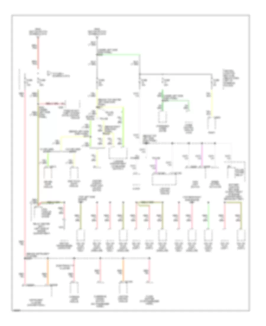 https://portal-diagnostov.com/license.html
Automotive Electricians Portal FZCO
Automotive Electricians Portal FZCO
https://portal-diagnostov.com/license.html
https://portal-diagnostov.com/license.html
Automotive Electricians Portal FZCO
Automotive Electricians Portal FZCOList of elements for Power Distribution Wiring Diagram (4 of 5) for Ford Crown Victoria Police Interceptor 2002:
- (behind instrument cluster) s276
- (behind left side dash panel) s218
- (behind top center left side dash panel) s211
- (behind top left side dash panel) s2009
- (top left side engine) s103
- (top rear right side engine) s151
- (under left side dash panel) s225
- (under left side dash panel) s279
- All others
- Battery junction box (bjb) (in right front of engine compartment, behind battery)
- C205a
- C205b
- C2145a
- C2145c
- C2220a
- C2220b
- C252
- C290c
- C501c
- Central junction box (cjb) (below dash, left of steering column)
- Clock
- Coil on plug (cop) 1
- Coil on plug (cop) 2
- Coil on plug (cop) 3 (gasoline)
- Coil on plug (cop) 3 (ngv)
- Coil on plug (cop) 4 (gasoline)
- Coil on plug (cop) 4 (ngv)
- Coil on plug (cop) 5 (gasoline)
- Coil on plug (cop) 5 (ngv)
- Coil on plug (cop) 6 (gasoline)
- Coil on plug (cop) 6 (ngv)
- Coil on plug (cop) 7
- Coil on plug (cop) 8
- Dash panel)
- Driver door module
- Electronic cluster
- Except police
- Floor shifter (five passenger model)
- From ignition switch (diagram 3 of 5)
- Fuse 15a
- Fuse 20a
- Fuse 25a
- Fuse 30a
- Fuse 5a
- Ignition transformer capacitor
- Instrument cluster (conventional)
- Lighting control module
- Luggage compartment lid release switch 3
- Main light switch
- Master window/ door lock/ unlock switch
- Nca
- One touch down module
- Overdrive cancel switch (six passenger model)
- Passive anti- theft system (pats) control module
- Pcm module power diode
- Police
- Police only
- Police power relay
- Radio
- Relay center box 1 (left side of engine compartment)
- Speed control actuator
- To fuse 4 (diagram 5 of 5)
- W/ keyless entry
- W/o keyless entry
- Warning lamps module
- Windshield wiper motor
- Wiper control module (wcm)
Power Distribution Wiring Diagram (5 of 5) for Ford Crown Victoria Police Interceptor 2002
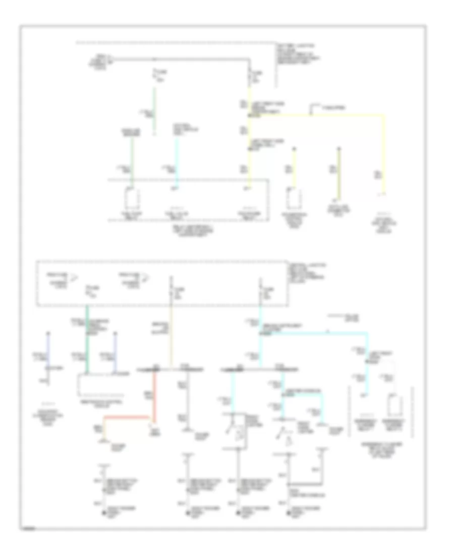 https://portal-diagnostov.com/license.html
Automotive Electricians Portal FZCO
Automotive Electricians Portal FZCO
https://portal-diagnostov.com/license.html
https://portal-diagnostov.com/license.html
Automotive Electricians Portal FZCO
Automotive Electricians Portal FZCOList of elements for Power Distribution Wiring Diagram (5 of 5) for Ford Crown Victoria Police Interceptor 2002:
- (behind bottom center right dash panel) s204
- (center console) s249
- (diagram 2 of 5)
- (left front side wheelwell) s100
- (not used)
- (right rocker panel) g201
- Battery junction box (bjb) (in right front of engine compartment, behind battery)
- C310b
- C3159a
- Central junction box (cjb) (below dash, left of steering column)
- Data link connector (dlc)
- Emergency flasher relay 1
- Emergency flasher relay 2
- Emergency flasher relay block (in left rear of trunk)
- Five passenger
- From fuse (diagram 4 of 5)
- From fuse 10 s (diagram 3 of 5)
- From fuse m
- Front cigar lighter
- Fuel pump relay
- Fuel valve relay
- Fuse 10a
- Fuse 20a
- Fuse 30a
- Gasoline engines
- If equipped
- Natural gas vehicle (ngv)
- Natural gas vehicle (ngv) module
- Nca
- Occupant classification sensor (ocs)
- Pcm power relay
- Police option
- Power point
- Powertrain control module (pcm)
- Relay center box 1 (left side of engine compartment)
- Restraints control module
- S248 (center console)
- Six passenger
POWER DOOR LOCKS
Power Door Lock Wiring Diagram, with Keyless Entry for Ford Crown Victoria Police Interceptor 2002
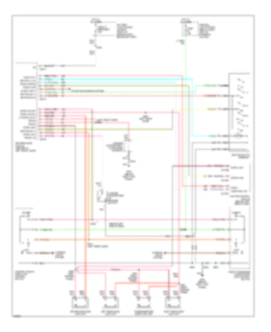 https://portal-diagnostov.com/license.html
Automotive Electricians Portal FZCO
Automotive Electricians Portal FZCO
https://portal-diagnostov.com/license.html
https://portal-diagnostov.com/license.html
Automotive Electricians Portal FZCO
Automotive Electricians Portal FZCOList of elements for Power Door Lock Wiring Diagram, with Keyless Entry for Ford Crown Victoria Police Interceptor 2002:
- (behind left side of dash)
- (left front door) s506
- 1/2
- 3/4
- 5/6
- 7/8
- 9/0
- Battery junction box (in right front of engine compt, behind battery)
- C2145a
- C2145b
- C2145c
- C501a
- C501b
- C501c
- Central junction box (below dash, left of steering column)
- Circuit breaker 7 20a
- Door ajar
- Door handle
- Door hndl sw
- Door lock
- Door unlock
- Driver side door lock unit
- Driver's door module (center of left front door)
- Front passenger window/door lock control switch
- Fuse 15a
- G200 (behind right kick panel)
- Hot at all times
- Interior lights system
- Keypad illum
- Keypad sw a
- Keypad sw b
- Keypad sw c
- Keypad switch assembly
- Left rear door lock unit
- Lf door unlck
- Lighting control module (behind left side of dash)
- Lock
- Luggage compartment lid release solenoid
- Luggage compartment lid release switch 1
- Master window/ door lock control switch
- Nca
- Panic
- Panic out
- Passenger side door lock unit
- Right rear door lock unit
- S208
- S228
- S235
- S245
- S260 (left rocker panel)
- S261 (right rocker panel)
- S291 (right rocker panel)
- S403
- S500
- S502 (left front door)
- S503
- S510 (left front door)
- S600
- Start input
- Starting/charging system
- Trunk
- Trunk lid
- Unlock
Power Door Lock Wiring Diagram, without Keyless Entry for Ford Crown Victoria Police Interceptor 2002
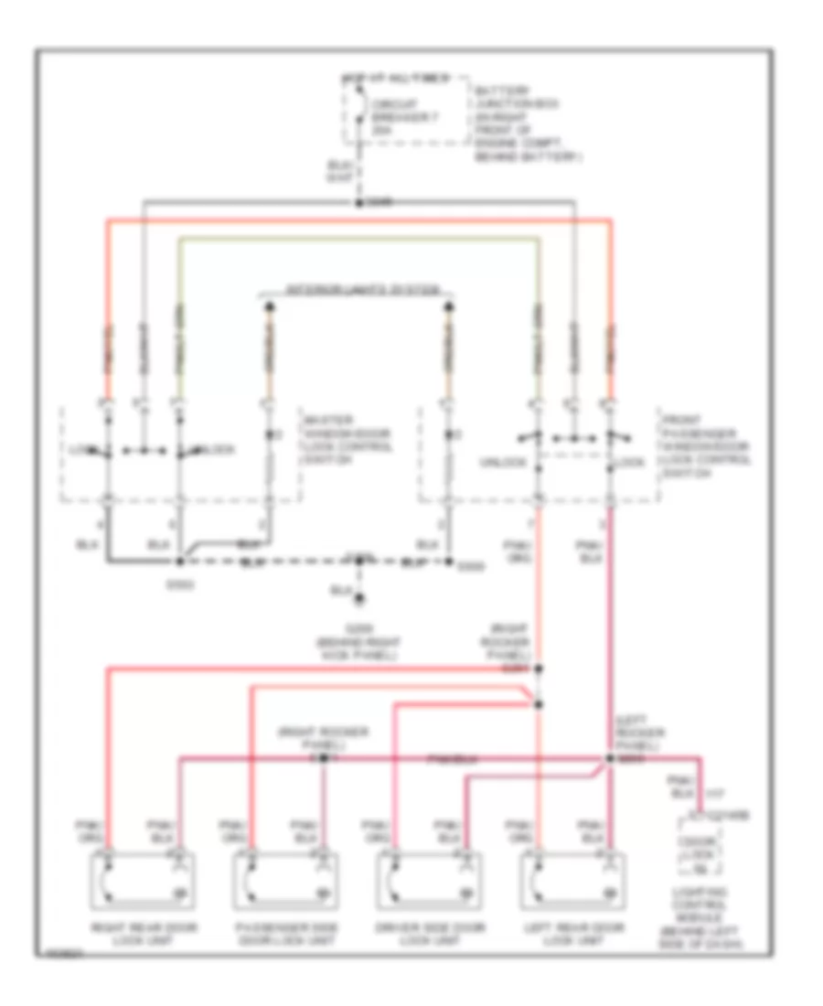 https://portal-diagnostov.com/license.html
Automotive Electricians Portal FZCO
Automotive Electricians Portal FZCO
https://portal-diagnostov.com/license.html
https://portal-diagnostov.com/license.html
Automotive Electricians Portal FZCO
Automotive Electricians Portal FZCOList of elements for Power Door Lock Wiring Diagram, without Keyless Entry for Ford Crown Victoria Police Interceptor 2002:
- (left rocker panel) s260
- (right rocker panel) s261
- (right rocker panel) s291
- Battery junction box (in right front of engine compt, behind battery)
- C2145b
- Circuit breaker 7 20a
- Door lock in
- Driver side door lock unit
- Front passenger window/door lock control switch
- G200 (behind right kick panel)
- Hot at all times
- Interior lights system
- Left rear door lock unit
- Lighting control module (behind left side of dash)
- Lock
- Master window/door lock control switch
- Passenger side door lock unit
- Right rear door lock unit
- S208
- S245
- S503
- S600
- Unlock
POWER MIRRORS
Electronic Day/Night Mirror Wiring Diagram for Ford Crown Victoria Police Interceptor 2002
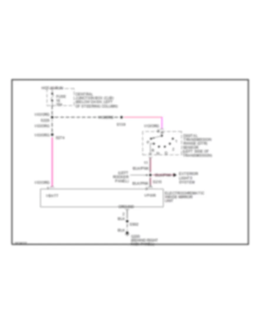 https://portal-diagnostov.com/license.html
Automotive Electricians Portal FZCO
Automotive Electricians Portal FZCO
https://portal-diagnostov.com/license.html
https://portal-diagnostov.com/license.html
Automotive Electricians Portal FZCO
Automotive Electricians Portal FZCOList of elements for Electronic Day/Night Mirror Wiring Diagram for Ford Crown Victoria Police Interceptor 2002:
- (left rocker panel)
- Central junction box (cjb) (below dash, left of steering column)
- Digital transmission range (dtr) sensor (left side of transmission)
- Electrochromatic inside mirror unit
- Exterior lights system
- Fuse 15a
- G200 (behind right kick panel)
- Ground
- Hot in run
- S139
- S215
- S226
- S274
- S902
- Vbatt
- Vpwr
Power Mirror Wiring Diagram for Ford Crown Victoria Police Interceptor 2002
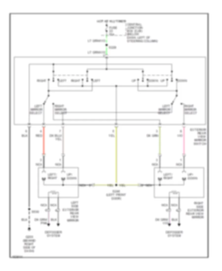 https://portal-diagnostov.com/license.html
Automotive Electricians Portal FZCO
Automotive Electricians Portal FZCO
https://portal-diagnostov.com/license.html
https://portal-diagnostov.com/license.html
Automotive Electricians Portal FZCO
Automotive Electricians Portal FZCOList of elements for Power Mirror Wiring Diagram for Ford Crown Victoria Police Interceptor 2002:
- Central junction box (cjb) (below dash, left of steering column)
- Defogger system
- Down
- Exterior rear view mirror switch
- Fuse 15a
- G200 (behind right side of dash)
- Hot at all times
- Left
- Left mirror select
- Left side exterior rear view mirror
- Left/ right
- Left/ right m
- Nca
- Red
- Right
- Right mirror select
- Right side exterior rear view mirror
- S228
- S246 (left front door)
- S500
- Up/ down m
POWER SEATS
6-Way Recliner & Lumbar Power Seat Wiring Diagram for Ford Crown Victoria Police Interceptor 2002
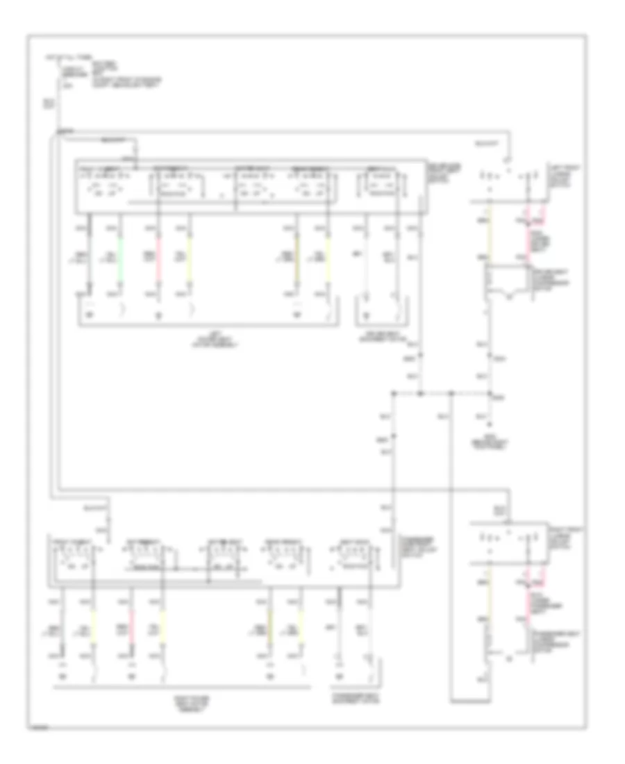 https://portal-diagnostov.com/license.html
Automotive Electricians Portal FZCO
Automotive Electricians Portal FZCO
https://portal-diagnostov.com/license.html
https://portal-diagnostov.com/license.html
Automotive Electricians Portal FZCO
Automotive Electricians Portal FZCOList of elements for 6-Way Recliner & Lumbar Power Seat Wiring Diagram for Ford Crown Victoria Police Interceptor 2002:
- nca
- Battery junction box (in right front of engine compt, behind battery)
- Circuit breaker 20a
- Driver seat backrest motor
- Driver seat lumbar compressor motor
- Driver side front seat adjust switch
- Entire seat
- Front of seat
- Fwd
- G200 (behind right kick panel)
- Hot at all times
- Left front lumbar adjust switch
- Left power seat motor assembly
- Nca
- Nca
- Passenger seat backrest motor
- Passenger seat lumbar compressor motor
- Passenger side front seat adjust switch
- Pnk
- Rear of seat
- Right front lumbar adjust switch
- Right power seat motor assembly
- Rwd
- S208
- S245
- S300 (under driver seat)
- S304
- S310 (under passenger seat)
- S500
- S600
- Seat back
- Up
Adjustable Pedal Wiring Diagram for Ford Crown Victoria Police Interceptor 2002
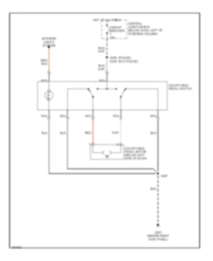 https://portal-diagnostov.com/license.html
Automotive Electricians Portal FZCO
Automotive Electricians Portal FZCO
https://portal-diagnostov.com/license.html
https://portal-diagnostov.com/license.html
Automotive Electricians Portal FZCO
Automotive Electricians Portal FZCOList of elements for Adjustable Pedal Wiring Diagram for Ford Crown Victoria Police Interceptor 2002:
- (police) (exc police)
- Adjustable pedal motor (below left side of dash)
- Adjustable pedal switch
- Central junction box (below dash, left of steering column)
- Circuit breaker 20a
- G201 (behind right kick panel)
- Hot at all times
- Interior lights system
- Nca
- Red
- S207
- S250 s245
Driver Power Seat Wiring Diagram for Ford Crown Victoria Police Interceptor 2002
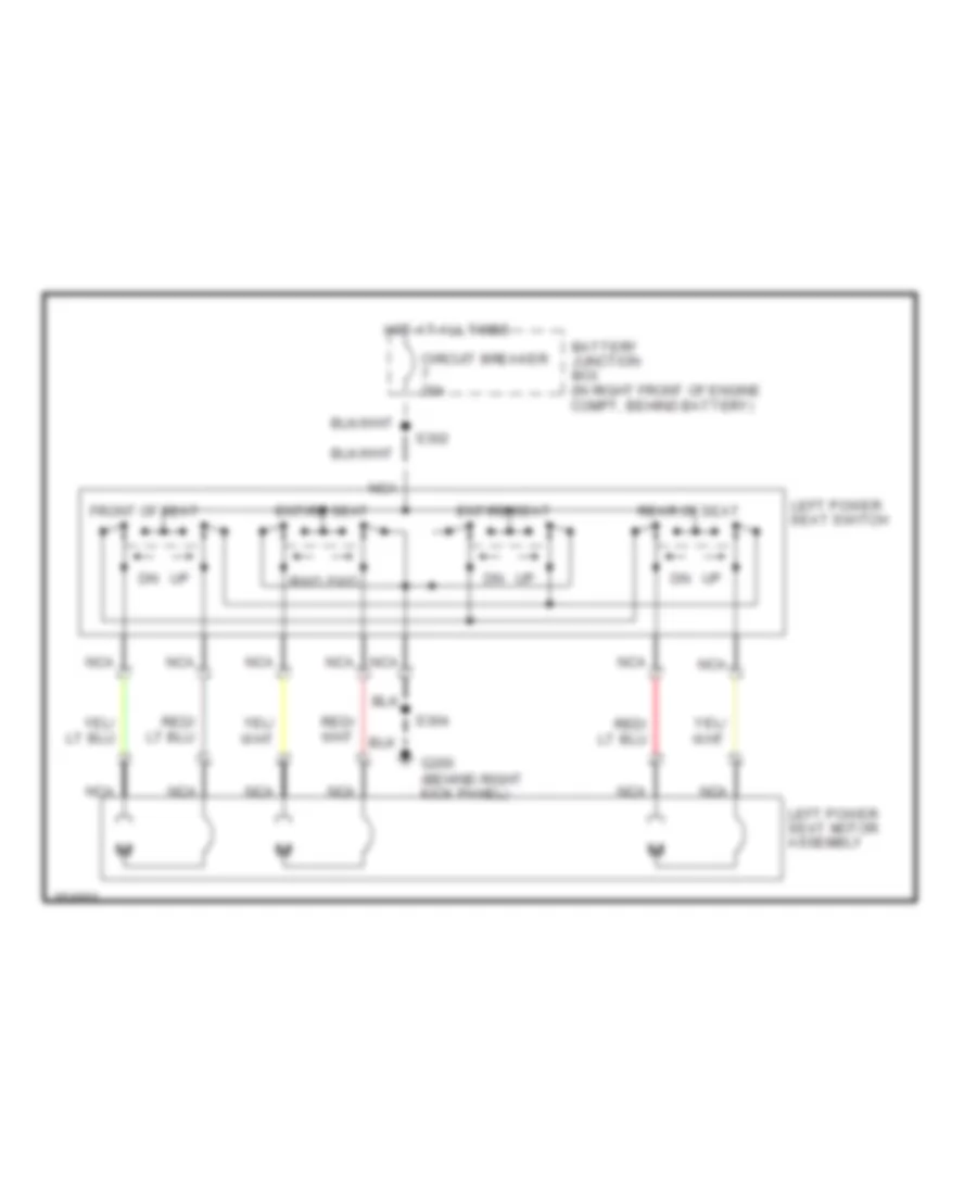 https://portal-diagnostov.com/license.html
Automotive Electricians Portal FZCO
Automotive Electricians Portal FZCO
https://portal-diagnostov.com/license.html
https://portal-diagnostov.com/license.html
Automotive Electricians Portal FZCO
Automotive Electricians Portal FZCOList of elements for Driver Power Seat Wiring Diagram for Ford Crown Victoria Police Interceptor 2002:
- Battery junction box (in right front of engine compt, behind battery)
- Circuit breaker 20a
- Entire seat
- Front of seat
- Fwd
- G200 (behind right kick panel)
- Hot at all times
- Left power seat motor assembly
- Left power seat switch
- Nca
- Rear of seat
- Rwd
- S302
- S304
POWER WINDOWS
Power Window Wiring Diagram for Ford Crown Victoria Police Interceptor 2002
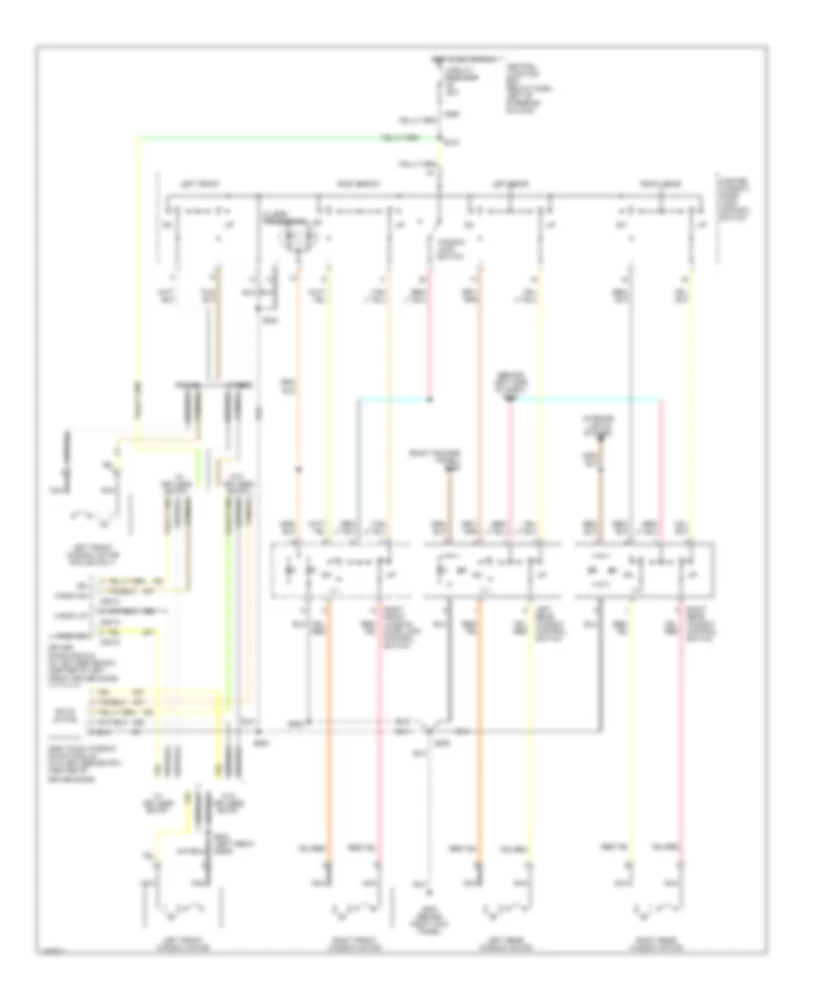 https://portal-diagnostov.com/license.html
Automotive Electricians Portal FZCO
Automotive Electricians Portal FZCO
https://portal-diagnostov.com/license.html
https://portal-diagnostov.com/license.html
Automotive Electricians Portal FZCO
Automotive Electricians Portal FZCOList of elements for Power Window Wiring Diagram for Ford Crown Victoria Police Interceptor 2002:
- (2 led's per switch)
- (behind left side of dash) s264
- (right rocker panel) s288
- C298
- C501a
- C501c
- Central junction box (below dash, left of steering column)
- Circuit breaker 20a
- Door lock control switch
- Driver door module (w/ keyless entry) (center of left
- Driver door)
- Entry
- Front driver door)
- G200 (behind right kick panel)
- Hot in acc or run
- Ign
- Interior lights system
- Keyless
- Left
- Left front
- Left front window motor
- Left front window motor (police only)
- Left rear
- Left rear window motor
- Master window/ door lock control switch
- Nca
- One touch window down module (w/o keyless entry) (center of
- Others
- Police
- Rear window control switch
- Right
- Right front
- Right front window motor
- Right rear
- Right rear window motor
- S208
- S218
- S500
- S503
- S600
- Solid state
- W/ keyless entry
- W/o
- W/o keyless entry
- Window lock switch
- Wndw dn
- Wndw up
RADIO
Base Radio Wiring Diagram for Ford Crown Victoria Police Interceptor 2002
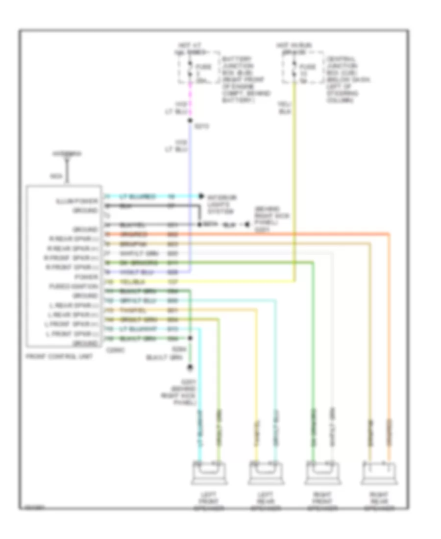 https://portal-diagnostov.com/license.html
Automotive Electricians Portal FZCO
Automotive Electricians Portal FZCO
https://portal-diagnostov.com/license.html
https://portal-diagnostov.com/license.html
Automotive Electricians Portal FZCO
Automotive Electricians Portal FZCOList of elements for Base Radio Wiring Diagram for Ford Crown Victoria Police Interceptor 2002:
- (behind right kick panel) g201
- Antenna
- Battery junction box (bjb) (right front of engine compt, behind battery)
- C290c
- Central junction box (cjb) (below dash, left of steering column)
- Front control unit
- Fuse 25a
- Fuse 5a
- Fused ignition
- G201 (behind right kick panel)
- Ground
- Hot at all times
- Hot in run or acc
- Illum power
- Interior lights system
- L front spkr (+)
- L front spkr (-)
- L rear spkr (+)
- L rear spkr (-)
- Left front speaker
- Left rear speaker
- Nca
- Power
- R front spkr (+)
- R front spkr (-)
- R rear spkr (+)
- R rear spkr (-)
- Right front speaker
- Right rear speaker
- S204
- S213
- S284
Premium Sound Radio Wiring Diagram, with Steering Wheel Controls for Ford Crown Victoria Police Interceptor 2002
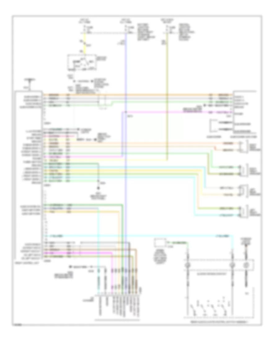 https://portal-diagnostov.com/license.html
Automotive Electricians Portal FZCO
Automotive Electricians Portal FZCO
https://portal-diagnostov.com/license.html
https://portal-diagnostov.com/license.html
Automotive Electricians Portal FZCO
Automotive Electricians Portal FZCOList of elements for Premium Sound Radio Wiring Diagram, with Steering Wheel Controls for Ford Crown Victoria Police Interceptor 2002:
- (behind right kick panel) g201
- Acc
- Antenna
- Audio (+)
- Audio (-)
- Audio mute
- Audio network
- Audio shield
- Audio system on
- Battery junction box (bjb) (right front of engine compt, behind battery)
- C122
- C290a
- C290b
- C290c
- C3028
- C401
- Cd changer
- Cd left sig in
- Cd left sig out
- Cd right sig in
- Cd right sig out
- Central junction box (cjb) (below dash, left of steering column)
- Front control unit
- Fuse 20a
- Fuse 25a
- Fuse 5a
- Fused ignition
- G201 (behind right kick panel)
- G402 (behind center of rear seats)
- G404 (behind center of rear seats)
- Ground
- Hot at all times
- Hot in run or acc
- Ignition switch
- Illum power
- Interior lights
- Interior lights system
- L front spkr (+)
- L front spkr (-)
- L rear spkr (+)
- L rear spkr (-)
- Left front speaker
- Left rear speaker
- Lock
- Nca
- Off
- Power
- R front spkr (+)
- R front spkr (-)
- R rear spkr (+)
- R rear spkr (-)
- Rear audio/climate control switch assembly
- Right front speaker
- Right rear speaker
- Run
- S127
- S204
- S213
- S267 (main harn, near breakout to ignition switch)
- S284
- S446
- Sliding air bag contact
- Speed control actuator (left rear of engine compt)
- Sta
- Start
- Start feed
- Starting system, door locks system
- Sub speaker
- Subwoofer
- Subwoofer (+)
- Subwoofer (-)
- Subwoofer amplifier
- Subwoofer mute
- Tan
Premium Sound Radio Wiring Diagram, without Steering Wheel Controls for Ford Crown Victoria Police Interceptor 2002
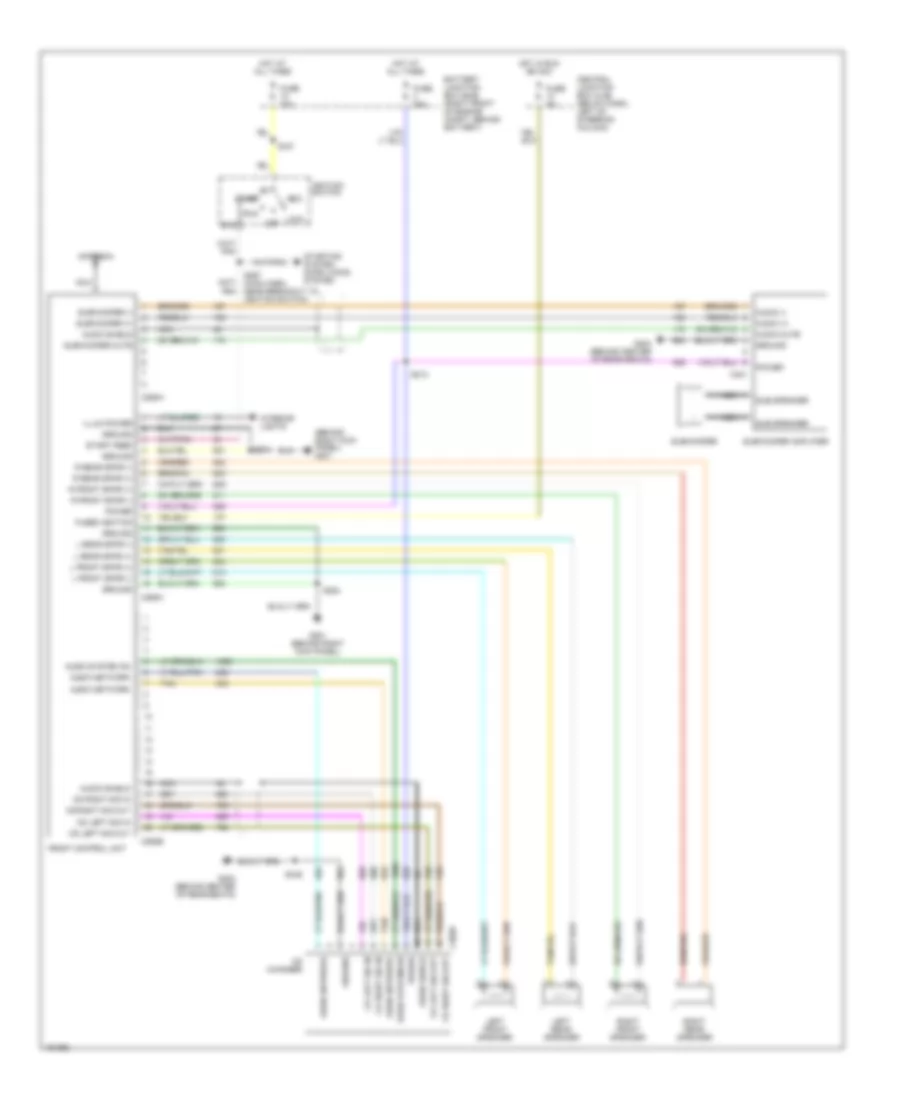 https://portal-diagnostov.com/license.html
Automotive Electricians Portal FZCO
Automotive Electricians Portal FZCO
https://portal-diagnostov.com/license.html
https://portal-diagnostov.com/license.html
Automotive Electricians Portal FZCO
Automotive Electricians Portal FZCOList of elements for Premium Sound Radio Wiring Diagram, without Steering Wheel Controls for Ford Crown Victoria Police Interceptor 2002:
- (behind right kick panel) g201
- Acc
- Antenna
- Audio (+)
- Audio (-)
- Audio mute
- Audio network
- Audio shield
- Audio system on
- Battery junction box (bjb) (right front of engine compt, behind battery)
- C290a
- C290b
- C290c
- C3028
- C401
- Cd changer
- Cd left sig in
- Cd left sig out
- Cd right sig in
- Cd right sig out
- Central junction box (cjb) (below dash, left of steering column)
- Front control unit
- Fuse 20a
- Fuse 25a
- Fuse 5a
- Fused ignition
- G201 (behind right kick panel)
- G402 (behind center of rear seats)
- G404 (behind center of rear seats)
- Ground
- Hot at all times
- Hot in run or acc
- Ignition switch
- Illum power
- Interior lights
- L front spkr (+)
- L front spkr (-)
- L rear spkr (+)
- L rear spkr (-)
- Left front speaker
- Left rear speaker
- Lock
- Nca
- Off
- Power
- R front spkr (+)
- R front spkr (-)
- R rear spkr (+)
- R rear spkr (-)
- Right front speaker
- Right rear speaker
- Run
- S127
- S204
- S213
- S267 (main harn, near breakout to ignition switch)
- S284
- S446
- Sta
- Start
- Start feed
- Starting system, door locks system
- Sub speaker
- Subwoofer
- Subwoofer (+)
- Subwoofer (-)
- Subwoofer amplifier
- Subwoofer mute
- Tan
SHIFT INTERLOCKS
Shift Interlock Wiring Diagram for Ford Crown Victoria Police Interceptor 2002
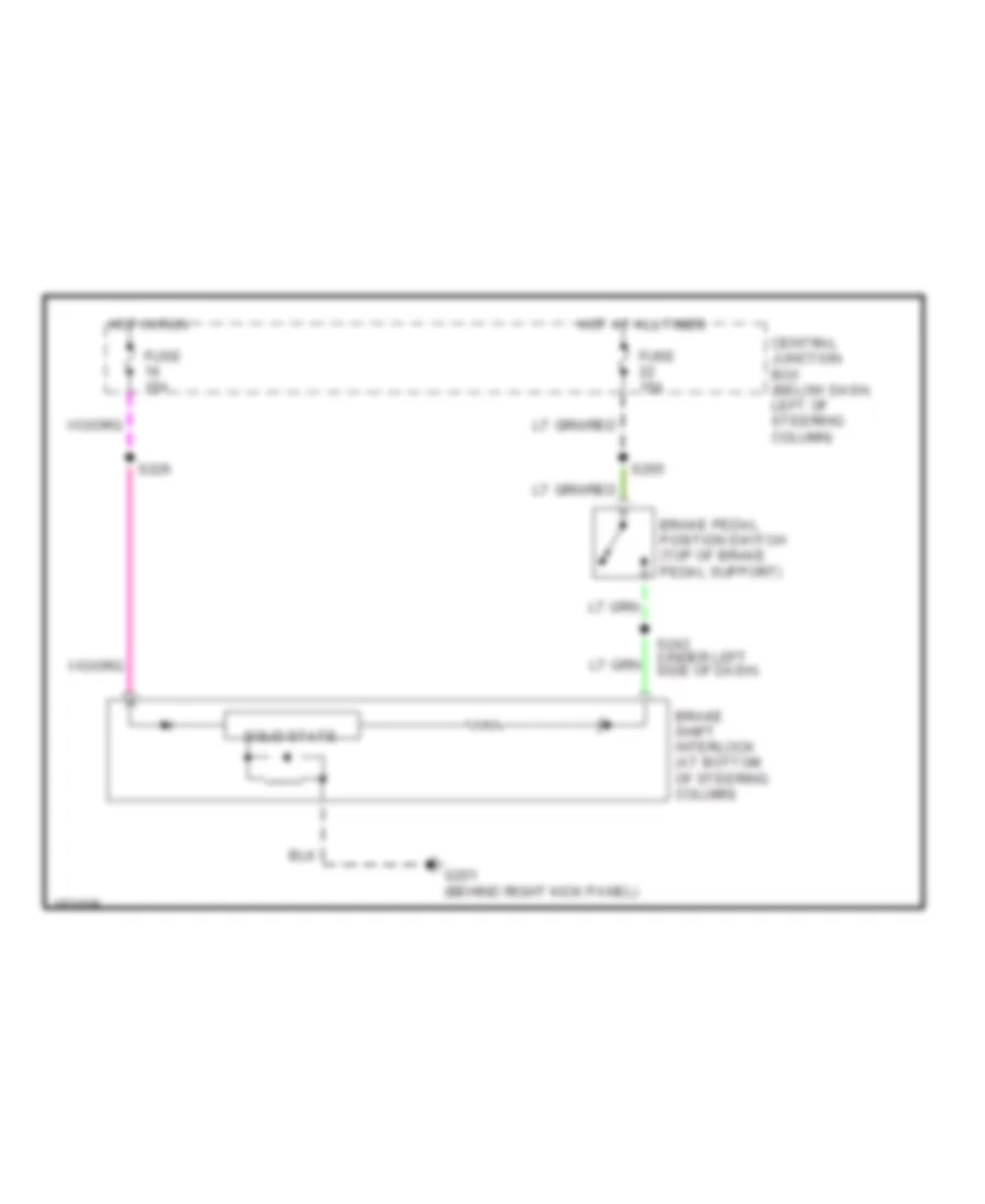 https://portal-diagnostov.com/license.html
Automotive Electricians Portal FZCO
Automotive Electricians Portal FZCO
https://portal-diagnostov.com/license.html
https://portal-diagnostov.com/license.html
Automotive Electricians Portal FZCO
Automotive Electricians Portal FZCOList of elements for Shift Interlock Wiring Diagram for Ford Crown Victoria Police Interceptor 2002:
- Brake pedal position switch (top of brake pedal support)
- Brake shift interlock (at bottom of steering column)
- Central junction box (below dash, left of steering column)
- Fuse 15a
- G201 (behind right kick panel)
- Hot at all times
- Hot in run
- S226
- S243 (under left side of dash)
- S265
- Solid state
STARTING/CHARGING
Charging Wiring Diagram for Ford Crown Victoria Police Interceptor 2002
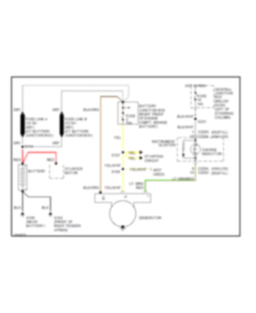 https://portal-diagnostov.com/license.html
Automotive Electricians Portal FZCO
Automotive Electricians Portal FZCO
https://portal-diagnostov.com/license.html
https://portal-diagnostov.com/license.html
Automotive Electricians Portal FZCO
Automotive Electricians Portal FZCOList of elements for Charging Wiring Diagram for Ford Crown Victoria Police Interceptor 2002:
- (analog)
- (digital)
- (not used)
- Battery
- Battery junction box (right front of engine compt, behind battery)
- C220a
- C220a c220c
- C220c
- Central junction box (below dash, left of steering column)
- Charge indicator
- Fuse 10a
- Fuse 30a
- G100 (near battery)
- G103 (front of right fender apron)
- Generator
- Hot in run
- Instrument cluster
- Red
- S106
- S114
- S127
- S231
- Starter motor
- Starting circuit
Starting Wiring Diagram for Ford Crown Victoria Police Interceptor 2002
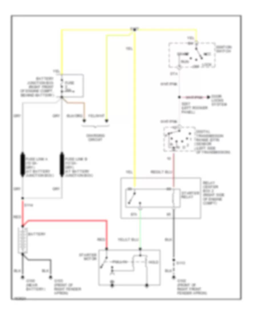 https://portal-diagnostov.com/license.html
Automotive Electricians Portal FZCO
Automotive Electricians Portal FZCO
https://portal-diagnostov.com/license.html
https://portal-diagnostov.com/license.html
Automotive Electricians Portal FZCO
Automotive Electricians Portal FZCOList of elements for Starting Wiring Diagram for Ford Crown Victoria Police Interceptor 2002:
- 87a
- Acc
- Battery
- Battery junction box (right front of engine compt, behind battery)
- Charging circuit
- Digital transmission range (dtr) sensor (left side of transmission)
- Door locks system
- Fuse 30a
- G100 (near battery)
- G102 (front of right front fender apron)
- G103 (front of right fender apron)
- Hold
- Ignition switch
- Lock
- Off
- Pull in
- Red
- Relay center box 2 (right side of engine compt)
- Run
- S113
- S114
- S127
- S267 (left rocker panel)
- Sta
- Start
- Starter motor
- Starter relay
SUPPLEMENTAL RESTRAINTS
Supplemental Restraint Wiring Diagram for Ford Crown Victoria Police Interceptor 2002
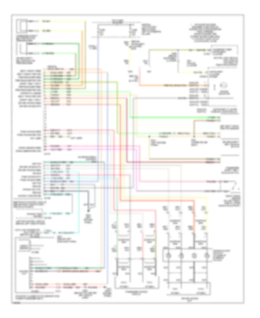 https://portal-diagnostov.com/license.html
Automotive Electricians Portal FZCO
Automotive Electricians Portal FZCO
https://portal-diagnostov.com/license.html
https://portal-diagnostov.com/license.html
Automotive Electricians Portal FZCO
Automotive Electricians Portal FZCOList of elements for Supplemental Restraint Wiring Diagram for Ford Crown Victoria Police Interceptor 2002:
- (analog)
- (analog) (digital)
- (behind instrument cluster) s276
- (digital)
- (not used)
- (on brake pedal support) s229
- Accessory feed instrument cluster
- Air bag ind ctrl
- Air bag indicator
- Air bag sliding contact (at base of steering column)
- Air bag tone driver
- C1009
- C2145a
- C2220a
- C2220b
- C2222
- C310a
- C310b
- C312
- C3159a
- C3159b
- Central junction box (below dash left of steering column)
- Control unit
- Crash sensor feed
- Crash sensor return
- Data link connector (dlc) (partial) (behind left side of dash)
- Driver air bag feed
- Driver air bag rtn
- Driver air bag unit
- Driver safety belt buckle switch
- Driver safety belt retractor pretensioner
- Front crash sensor (on left front side of upper radiator support)
- Fuse f2.4 10a
- Fuse f2.6 15a
- G201 (right rocker panel)
- G204 (left rocker panel)
- Gas
- Ground
- Horizontal sense
- Hot in run or start
- Ignition
- Instrument cluster power
- Instrument cluster warning lamps module
- Iso bus
- Left seat track position sensor
- Lighting control module (behind left side of dash)
- Natural gas vehicle (ngv) module (on front of radiator support)
- Nca
- Ngv
- Ngv analog cluster
- Not used
- Occupant classification sensor (ocs) (under passenger seat)
- Pass air bag feed
- Pass air bag return
- Pass air bag rtn
- Passenger air bag module
- Passenger safety belt buckle switch
- Passenger safety belt retractor pretensioner
- Pin shorting bars engaged when module connector is disconnected from harness (shorting bars are connected between pins: 11-12 & 20-21 conn. c310a 2-3 & 5-6 conn. c310b
- Pretensioner feed
- Pretensioner return
- Restraints control module (behind right side of dash, above glove box)
- S200 (behind top center left side of dash)
- S214 (left rocker panel)
- S241 (behind left side dash panel)
- S299 (behind instrument cluster)
- S301 (under driver seat)
- Safety belt input
- Seat track return
- Seat weight feed
- Seat weight return
- Shorting bar
- Stage 1
- Stage 2
- Weight sensor
TRANSMISSION
A/T Wiring Diagram for Ford Crown Victoria Police Interceptor 2002
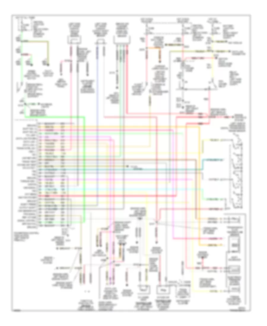 https://portal-diagnostov.com/license.html
Automotive Electricians Portal FZCO
Automotive Electricians Portal FZCO
https://portal-diagnostov.com/license.html
https://portal-diagnostov.com/license.html
Automotive Electricians Portal FZCO
Automotive Electricians Portal FZCOList of elements for A/T Wiring Diagram for Ford Crown Victoria Police Interceptor 2002:
- (behind air cleaner assembly) mass air- flow (maf) sensor
- (dash harn, near breakout to data link connector)
- (engine compt harn, lower left of engine)
- (engine compt harn, near front crash sensor)
- (engine compt harn, right rear of engine)
- (engine harn, left rear corner of engine compt)
- (engine harn, left rear of engine compt)
- (engine harn, left rear of engine compt) s129
- (left side of trans- mission)
- (left side of trans- mission) output shaft speed (oss) sensor
- (left side of transmission) digital transmission range sensor
- (rear of left front fender apron)
- (rear of left front fender g101 apron)
- (trans harn, left rear of engine compartment)
- (trans harn, left rear of trans)
- 4r70w transmission
- A/c cutout
- Abs module,
- Analog
- Anti-theft system,
- Battery junction box (right front of engine compt)
- Bpp switch
- Brake pedal position (bpp) switch (top of brake pedal support)
- C220b
- Central junction box (below dash, left of steering column)
- Cht sens
- Cylinder head
- Data link +
- Data link -
- Data link connector
- Data link connector (partial) (behind left side of dash)
- Data link power
- Digital
- Eatc module
- Elect press
- Electronic pressure control solenoid
- Engine controls system
- Exterior lights
- Floor shifter (5 pass- enger vehicle)
- Fuse 15a
- Fuse 25a
- Fuse 30a
- G101
- G101 (rear of left front fender apron)
- G201 (behind
- Ground
- Hot at all times
- Hot in run or start
- Ignition coils, radio noise capacitor
- Ignition power
- Instrument cluster
- Instrument cluster, cruise control, electronic suspension
- Intake air
- Intake air temp
- Kapwr
- Lighting control module, instrument cluster
- Maf return
- Maf sensor sig
- Multi- function switch
- Ngv module
- Output shaft
- Overdrive cancel switch (6 passenger vehicle)
- Passive anti-theft system control module
- Pcm power diode
- Pcm power relay
- Powertrain control module (pcm) (left side of firewall)
- R p
- Red
- Red red
- Ref votage
- Relay center box 1 (left side of engine compt)
- Right kick panel)
- S100
- S105
- S115
- S119
- S123
- S125
- S126
- S132
- S134
- S135
- S147
- S148
- S155
- S223
- S263
- S265
- S276
- S296
- S297
- Shift sol a
- Shift sol b
- Shift solenoids
- Signal control
- Speed control deactivator switch
- Ss a
- Ss b
- System
- Tci lamp
- Temperature (cht) sensor (top left front of engine)
- Temperature (iat) sensor (left front of engine) compt)
- Throttle position (tp) sensor (left side of throtle body)
- To a/c
- Torque conv
- Torque converter clutch (tcc) solenoid
- Tps signal
- Tr1
- Tr2
- Tr3
- Tr4
- Trans cntrl sw
- Trans control indicator lamp
- Trans temp
- Transmission fluid temperature sensor
- Vehicle speed sensor
- Vss (-)
- Vss signal
- Warning lamps module,
TRUNK, TAILGATE, FUEL DOOR
Fuel Door Release Wiring Diagram for Ford Crown Victoria Police Interceptor 2002
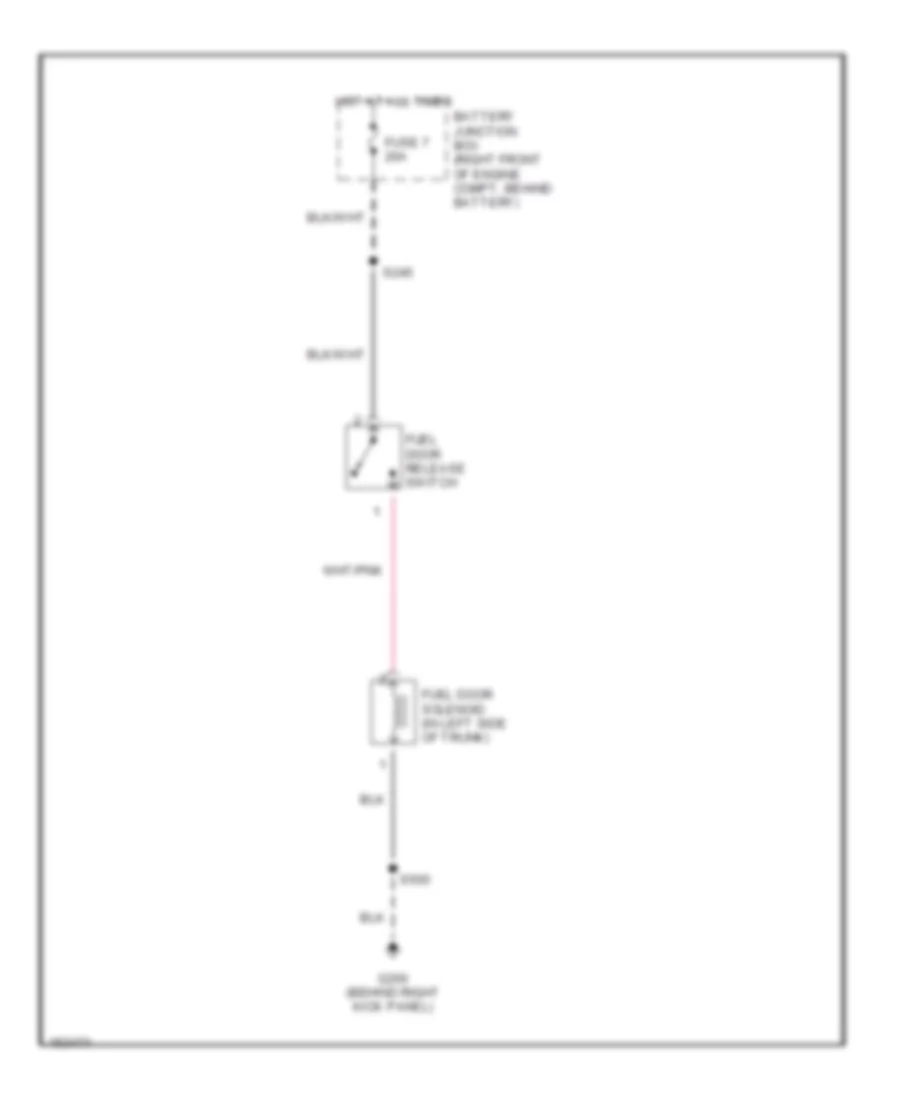 https://portal-diagnostov.com/license.html
Automotive Electricians Portal FZCO
Automotive Electricians Portal FZCO
https://portal-diagnostov.com/license.html
https://portal-diagnostov.com/license.html
Automotive Electricians Portal FZCO
Automotive Electricians Portal FZCOList of elements for Fuel Door Release Wiring Diagram for Ford Crown Victoria Police Interceptor 2002:
- Battery junction box (right front of engine compt, behind battery)
- Fuel door release switch
- Fuel door solenoid (in left side of trunk)
- Fuse 7 20a
- G200 (behind right kick panel)
- Hot at all times
- S245
- S500
Trunk Release Wiring Diagram, with Keyless Entry for Ford Crown Victoria Police Interceptor 2002
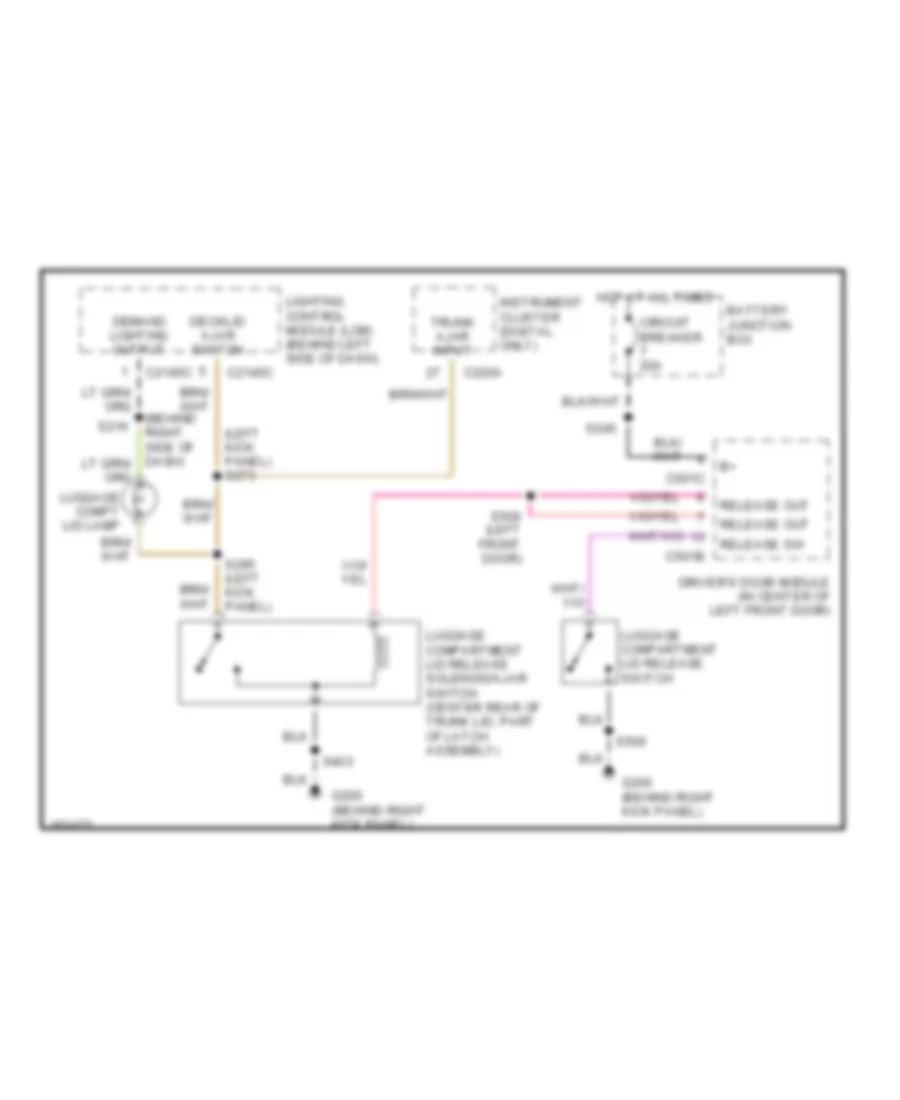 https://portal-diagnostov.com/license.html
Automotive Electricians Portal FZCO
Automotive Electricians Portal FZCO
https://portal-diagnostov.com/license.html
https://portal-diagnostov.com/license.html
Automotive Electricians Portal FZCO
Automotive Electricians Portal FZCOList of elements for Trunk Release Wiring Diagram, with Keyless Entry for Ford Crown Victoria Police Interceptor 2002:
- (left kick panel) s273
- Battery junction box
- C2145c
- C220a
- C501b
- C501c
- Circuit breaker 20a
- Decklid ajar switch
- Demand lighting output
- Driver's door module (in center of left front door)
- G200 (behind right kick panel)
- Hot at all times
- Instrument cluster (digital only)
- Lighting control module (lcm) (behind left side of dash)
- Luggage compartment lid release solenoid/ajar switch (center rear of trunk lid, part of latch assembly)
- Luggage compartment lid release switch
- Luggage compt lid lamp
- Release out
- Release sw
- S216
- S245
- S295 (left kick panel)
- S403
- S500
- S506 (left front door)
- Trunk ajar input
Trunk Release Wiring Diagram, without Keyless Entry for Ford Crown Victoria Police Interceptor 2002
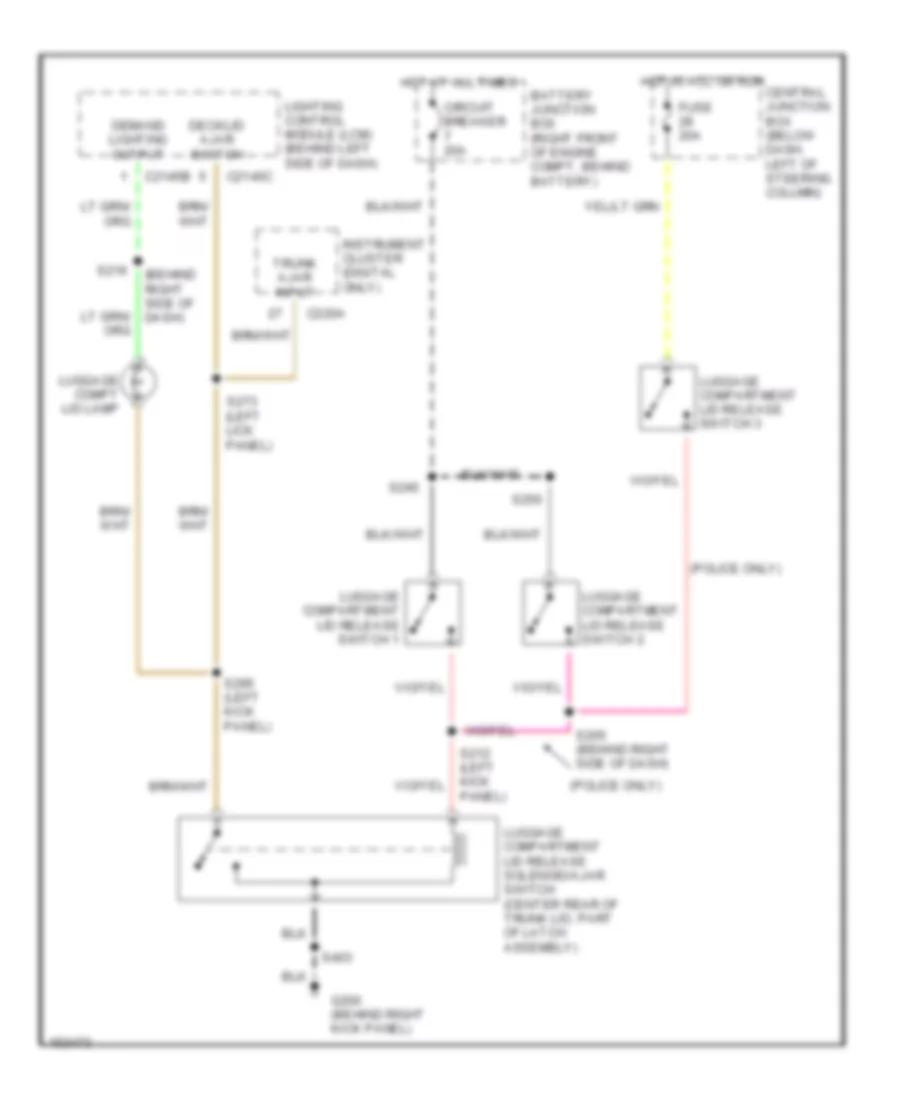 https://portal-diagnostov.com/license.html
Automotive Electricians Portal FZCO
Automotive Electricians Portal FZCO
https://portal-diagnostov.com/license.html
https://portal-diagnostov.com/license.html
Automotive Electricians Portal FZCO
Automotive Electricians Portal FZCOList of elements for Trunk Release Wiring Diagram, without Keyless Entry for Ford Crown Victoria Police Interceptor 2002:
- (behind right side of dash)
- (police only)
- Battery junction box (right front of engine compt, behind battery)
- C2145b
- C2145c
- C220a
- Central junction box (below dash, left of steering column)
- Circuit breaker 20a
- Decklid ajar switch
- Demand lighting output
- Fuse 20a
- G200 (behind right kick panel)
- Hot at all times
- Hot in acc or run
- Instrument cluster (digital only)
- Lighting control module (lcm) (behind left side of dash)
- Luggage compartment lid release solenoid/ajar switch (center rear of trunk lid, part of latch assembly)
- Luggage compartment lid release switch 1
- Luggage compartment lid release switch 2
- Luggage compartment lid release switch 3
- Luggage compt lid lamp
- Panel)
- S205 (behind right side of dash)
- S216
- S245
- S250
- S273 (left lick panel)
- S295 (left kick panel)
- S403
- Trunk ajar input
WARNING SYSTEMS
Warning System Wiring Diagrams for Ford Crown Victoria Police Interceptor 2002
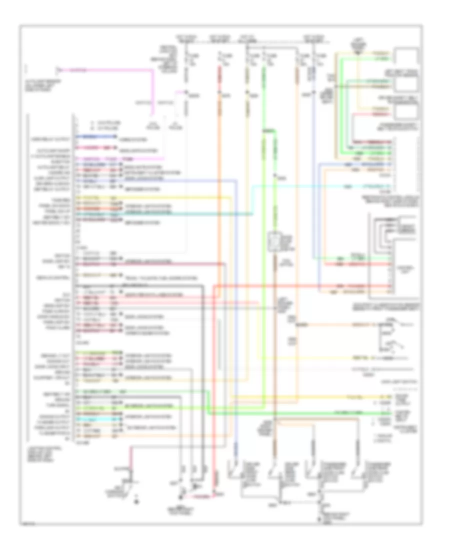 https://portal-diagnostov.com/license.html
Automotive Electricians Portal FZCO
Automotive Electricians Portal FZCO
https://portal-diagnostov.com/license.html
https://portal-diagnostov.com/license.html
Automotive Electricians Portal FZCO
Automotive Electricians Portal FZCOList of elements for Warning System Wiring Diagrams for Ford Crown Victoria Police Interceptor 2002:
- (behind right kick panel) g200
- (left rocker panel) s214
- (left rocker panel) s280
- (police only)
- (w/ police)
- (w/o police)
- Ajar lamp output
- Analog
- Autolamp delay
- Autolamp enable
- Autolamp on/off
- Autolamp sensor (on upper left side of dash)
- C145a
- C205a
- C2145b
- C2145c
- C220b
- C220c
- C2220a
- C310a
- C310b
- Central junction box (behind dash, left of steering column)
- Computer data lines system
- Control unit
- Courtesy lps out
- Decklid control
- Def relay output
- Defogger system
- Demand lt out
- Digital
- Dimming out
- Dimming output
- Dlc
- Dome lamp sw
- Door ajar indi- cator
- Door handle sw
- Door locks input
- Door locks system
- Driver safety belt buckle switch
- Driver side front door ajar switch
- Driver side rear door ajar switch
- Driver's ajar sw
- Exterior lights system
- Fasten belts input
- Flasher output
- Flasher pwr in
- Fuse 10a
- Fuse 15a
- Fuse 25a
- G201 (behind right kick panel)
- Ground
- Hazard ind
- Head
- Headlamp sw
- Headlights system
- Heated backlt sw
- Horn relay output
- Horns system
- Hot at all times
- Hot in run or accy
- Hot in run or start
- Ignition
- Instrument cluster
- Instrument cluster system
- Interior lights system
- Key in
- Key warning switch
- Left seat track position sensor
- Lighting control module (lcm) (behind left side of dash)
- Main light switch
- Nca
- Occupant classification sensor (beneath front passenger seat)
- Off
- Panel dim down
- Panel dim up
- Panic alarm
- Park
- Parklamp output
- Parklamp sw
- Pass ajar sw
- Passenger safety belt buckle switch
- Passenger side front door ajar switch switch
- Passenger side rear door ajar switch switch
- Restraints control module (behind right side of dash, above glove box)
- S200
- S2009
- S204
- S207
- S227
- S229
- S259 (right rocker panel)
- S276
- S282
- S285
- S301 (under driver seat)
- S500
- S600
- Seatbelt ind
- Seatbelt sw
- Sound tone output
- Taxi option
- Tone req
- Trunk, tailgate, fuel doors system
- Turn signal
- W/ police
- W/o police
- Weight sensor
- Wiper/washer system
WIPER/WASHER
Wiper/Washer Wiring Diagram for Ford Crown Victoria Police Interceptor 2002
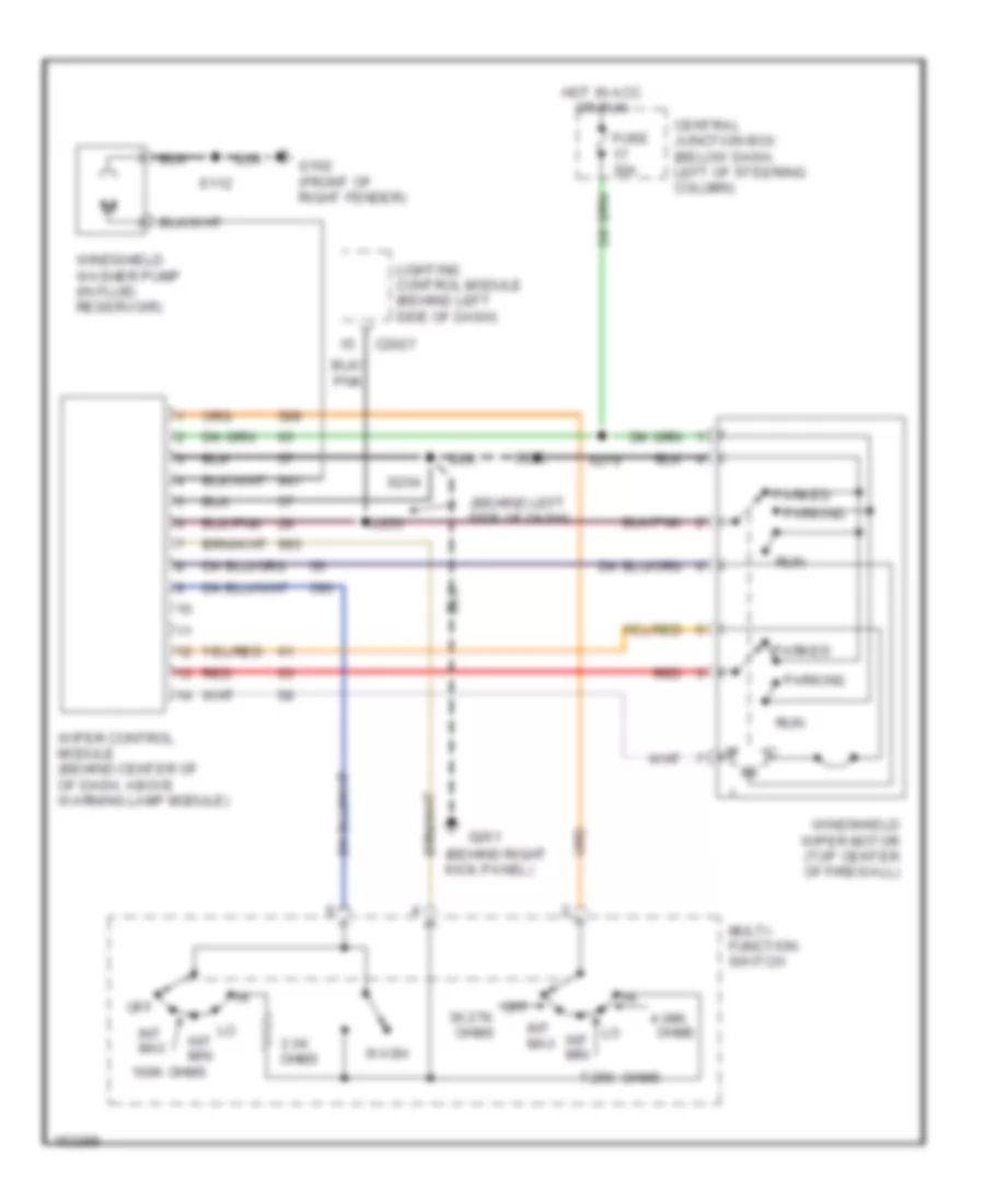 https://portal-diagnostov.com/license.html
Automotive Electricians Portal FZCO
Automotive Electricians Portal FZCO
https://portal-diagnostov.com/license.html
https://portal-diagnostov.com/license.html
Automotive Electricians Portal FZCO
Automotive Electricians Portal FZCOList of elements for Wiper/Washer Wiring Diagram for Ford Crown Victoria Police Interceptor 2002:
- (behind left side of dash)
- (behind right kick panel)
- 100k ohms
- 3.3k ohms
- 4.08k
- 7.25k
- C2027
- Central junction box (below dash, left of steering column)
- Fuse 30a
- G102 (front of right fender)
- G201
- Hot in acc or run
- Int max
- Int min
- Lighting control module (behind left side of dash)
- Multi- function switch
- Off
- Off 36.27k ohms
- Ohms
- Parked
- Parking
- Red
- Run
- S112
- S203
- S204
- S253
- S279
- Wash
- Windshield washer pump (in fluid reservoir)
- Windshield wiper motor (top center of firewall)
- Wiper control module (behind center of of dash, above warning lamp module)

 Čeština
 Dansk
Dansk Deutsch
 Ελληνικά
 English
 English
 Español
 Suomi
Suomi Français
 Français
 עברית
עברית Hrvatski
 Magyar
 Italiano
 한국어
한국어 Nederlands
 Polski
 Português
 Português
 Română
 Русский
 Slovenčina
 Slovenščina
 Svenska
 Türkçe
 中文 (中国)
