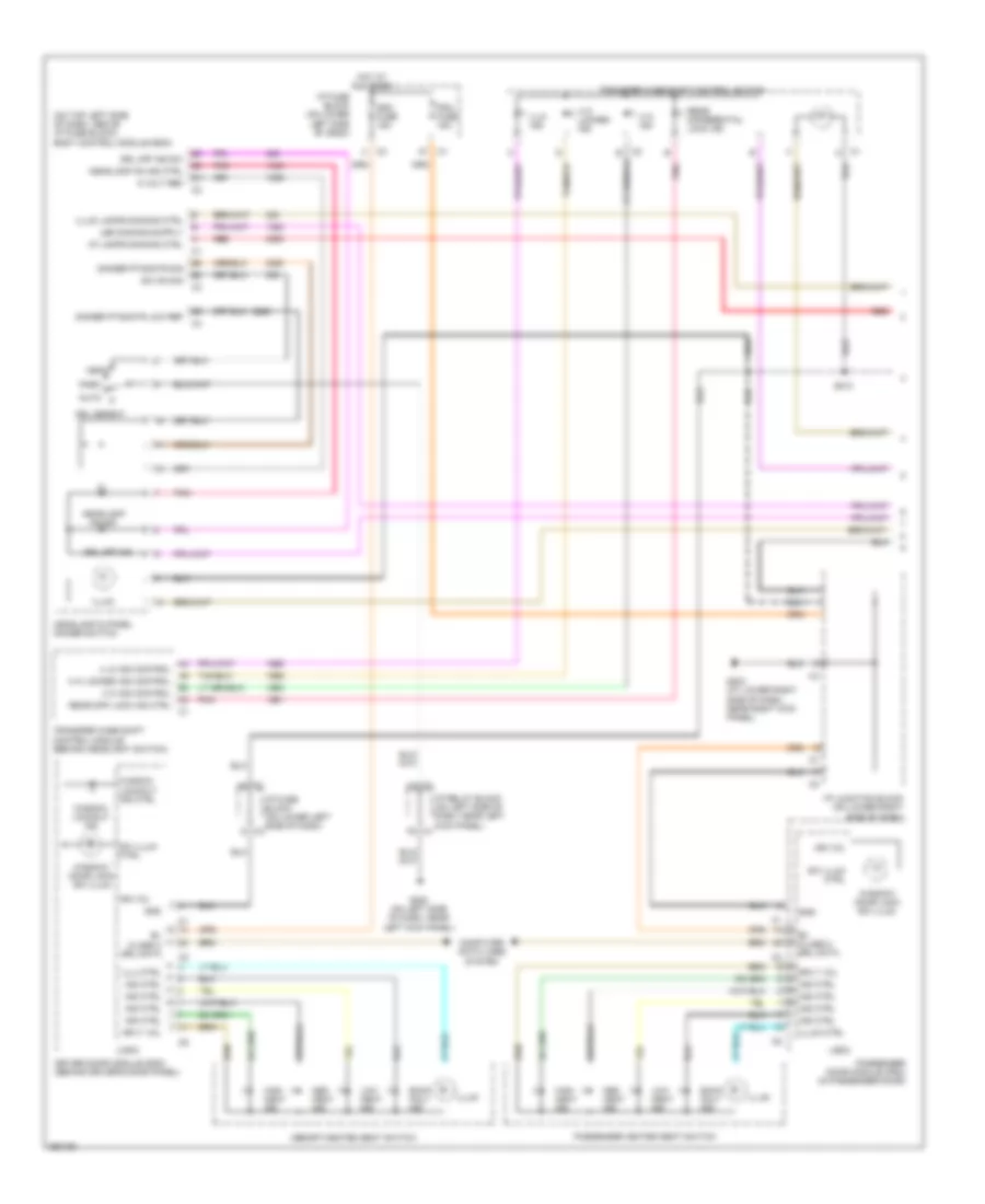
AIR CONDITIONING
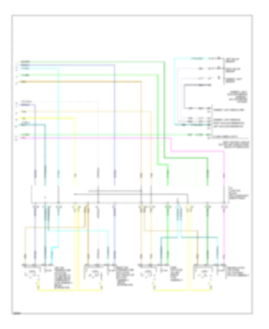
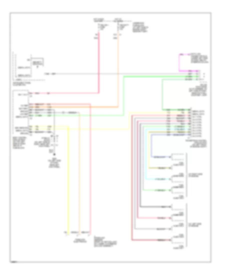
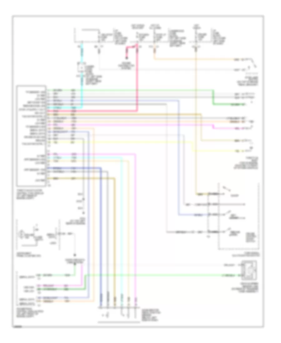
Automatic A/C Wiring Diagram (1 of 2) for Hummer H2 2007
 https://portal-diagnostov.com/license.html
Automotive Electricians Portal FZCO
Automotive Electricians Portal FZCO
https://portal-diagnostov.com/license.html
https://portal-diagnostov.com/license.html
Automotive Electricians Portal FZCO
Automotive Electricians Portal FZCO
List of elements for Automatic A/C Wiring Diagram (1 of 2) for Hummer H2 2007:
- 5v ref
- A/c comp cl rly ctrl
- A/c comp fuse 10a
- A/c compressor clutch
- A/c compressor relay
- A/c low pressure switch (right side of accumulator)
- A/c on
- A/c recirc
- A/c ref pre sens sig
- A/c refrigerant pressure sensor (in rear of a/c compressor)
- A10
- A11
- A12
- A5 c1
- Amb air temp sig
- Ambient air temperature sensor (at right front of vehicle, to right of radiator support)
- B c5
- B(+)
- B10
- B11
- B12
- Blower fuse 40a
- Blower motor (at right lower side of dash, on hvac assembly)
- Blower motor control processor (behind right side of dash, on hvac assembly)
- Blower speed ctrl
- C4 e
- Class 2 ser data
- Class 2 serial data
- D red
- F8 c1
- Frt def
- G104 (at top left rear of engine)
- G200 (on left side of dash, near left kick panel)
- G203 (at lower right side of dash, near right kick panel)
- Ground
- Hot at all times
- Hot in run
- Hot in run or start
- Hvac 1 fuse 10a
- Hvac control module (center of dash)
- Hvac/ ecas fuse 10a
- I/p fuse block (on lower left side of dash)
- I/p junction block (on lower right side of dash)
- I/p relay block (on left side of dash, near left kick panel)
- Ign 3
- Ign e fuse 10a
- Inside air temp sig
- Inside air temperature sensor assembly
- Inst lamp dim ctrl
- Interior lights system
- Left temp control
- Lo lt air temp sig
- Lo press sens sig
- Lo rt air temp sig
- Logic
- Low ref
- Lower left air temperature sensor
- Lower right air temperature sensor
- Lt temp door ctrl
- Mirrors system
- Mode
- Mode door ctrl
- Powertrain control module (left front of engine compt)
- Rear def
- Recir
- Recir door ctrl
- Recirc door po sig
- Red
- Right temp control
- Rt temp door ctrl
- S102 (in engine harness, 4 cm from knock sensor connector)
- S214 (in i/p harness, 50.4 cm from junction of instrument cluster connector harness to i/p harness)
- S216 (in i/p harness, 2.5 cm from junction of air temperature sensor)
- S301
- Sp 205 (in i/p harness, on left side of dash, near footwell courtesy lamp)
- Speed ctrl
- Tan
- Temp sen assy ctrl
- Underhood fuse block (at left side of engine compt, near battery)
- Up lt air temp sig
- Up rt air temp sig
- Upper left air temperature sensor (at left side of dash panel)
- Upper right air temperature sensor (at right side of dash panel)
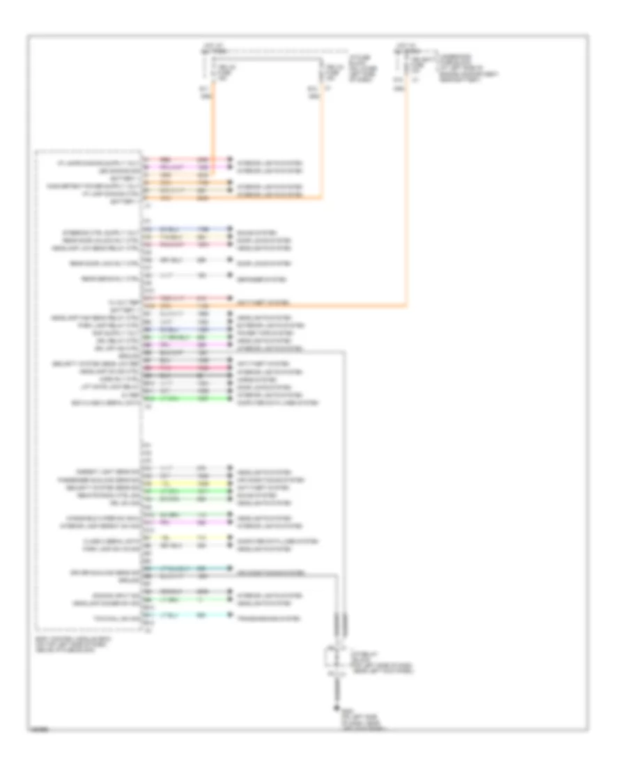
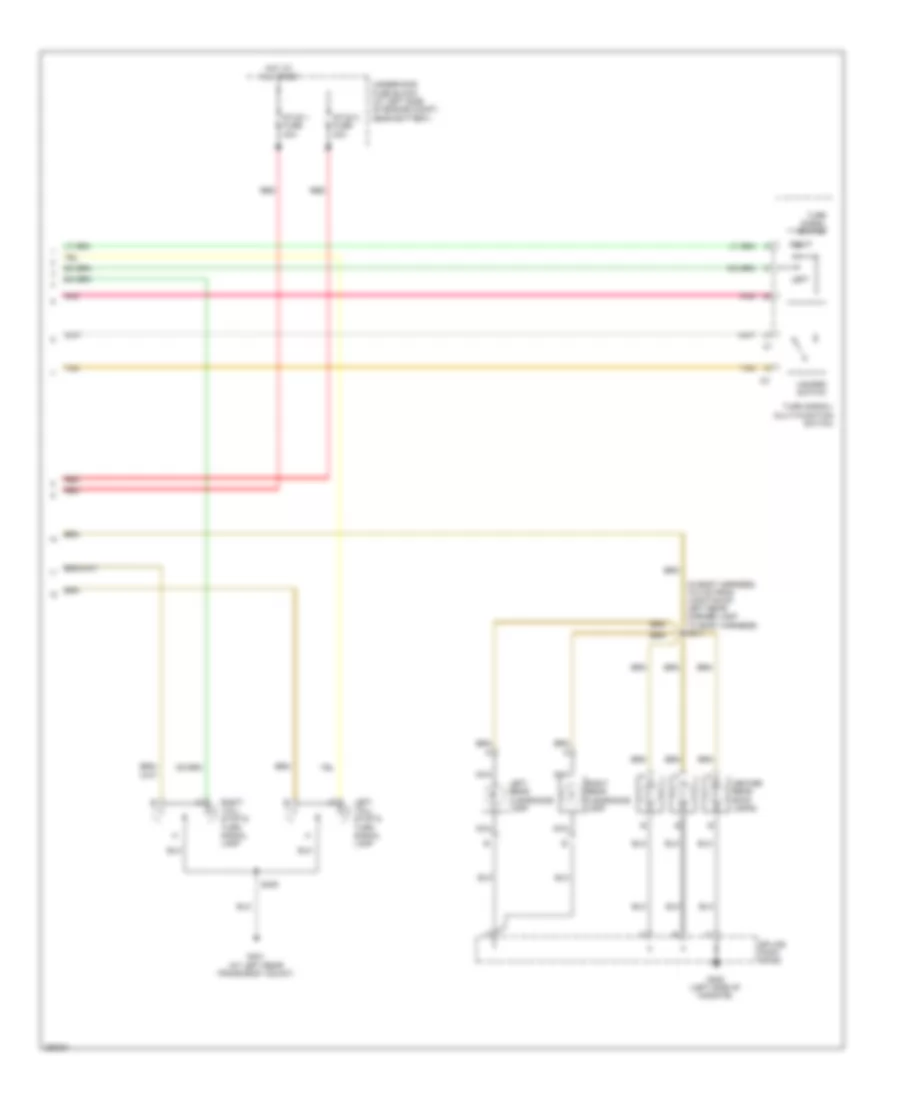
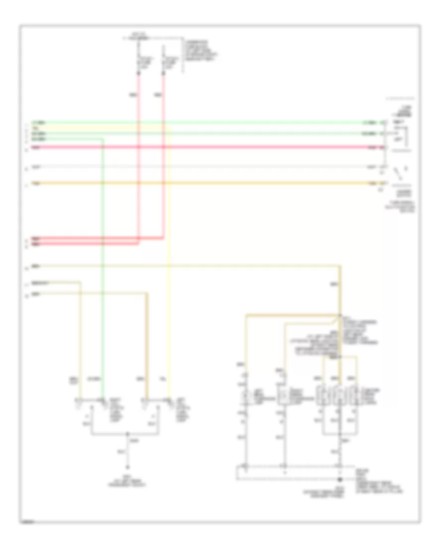
Automatic A/C Wiring Diagram (2 of 2) for Hummer H2 2007
 https://portal-diagnostov.com/license.html
Automotive Electricians Portal FZCO
Automotive Electricians Portal FZCO
https://portal-diagnostov.com/license.html
https://portal-diagnostov.com/license.html
Automotive Electricians Portal FZCO
Automotive Electricians Portal FZCOList of elements for Automatic A/C Wiring Diagram (2 of 2) for Hummer H2 2007:
- Ambient light sens lo ref
- Ambient light sens sig
- Ambient light sensor
- Ambient light/ sunload sensor assembly (on top center of dash)
- B12
- Body control module (on top left side of dash, above i/p fuse block)
- Class 2 serial data
- I/p junction block (on lower right side of dash)
- Left air temperature actuator (attached to lower middle underside of hvac assembly, below evaporator)
- Left solar sensor
- Left sunload sensor sig
- Logic
- Mode actuator (on left side of hvac assembly)
- Recirculation actuator (on top front of hvac assembly)
- Right air temperature actuator (at middle top of hvac assembly, above evaporator)
- Right solar sensor
- Right sunload sensor sig
- Tan
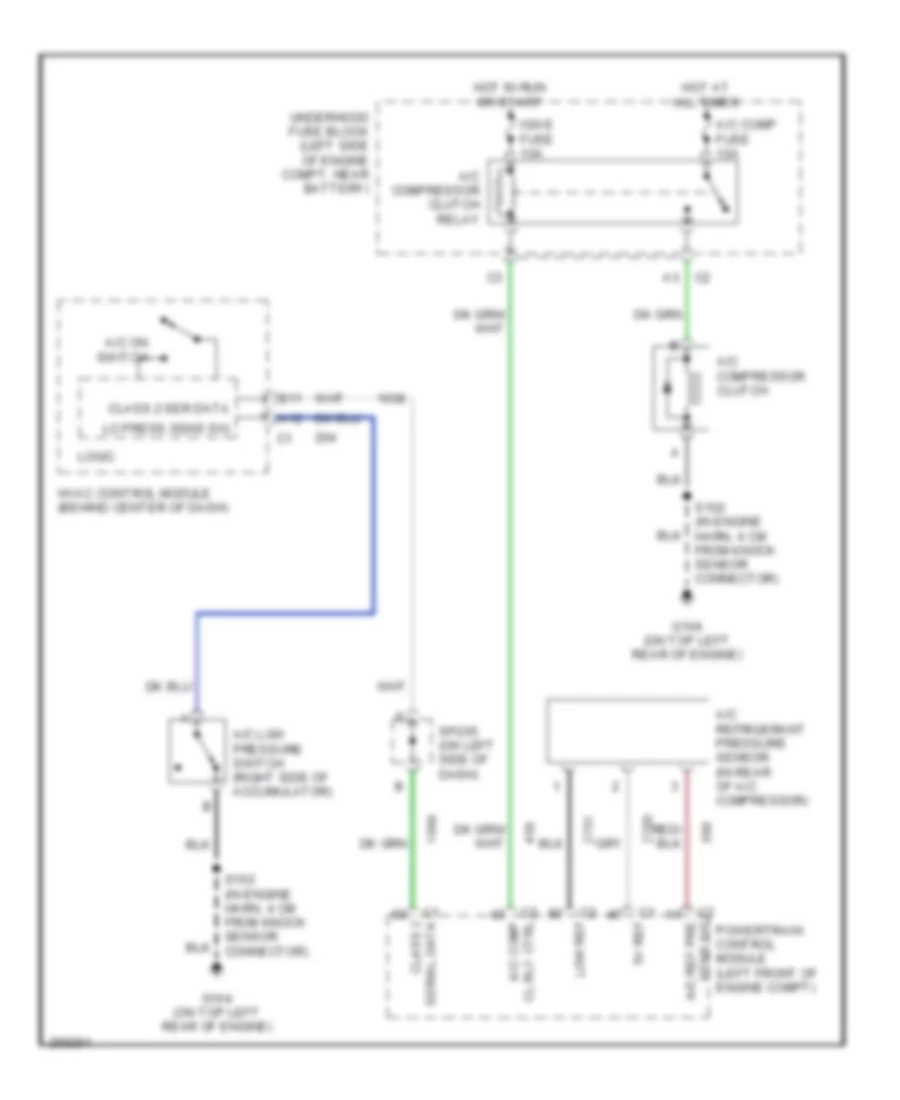
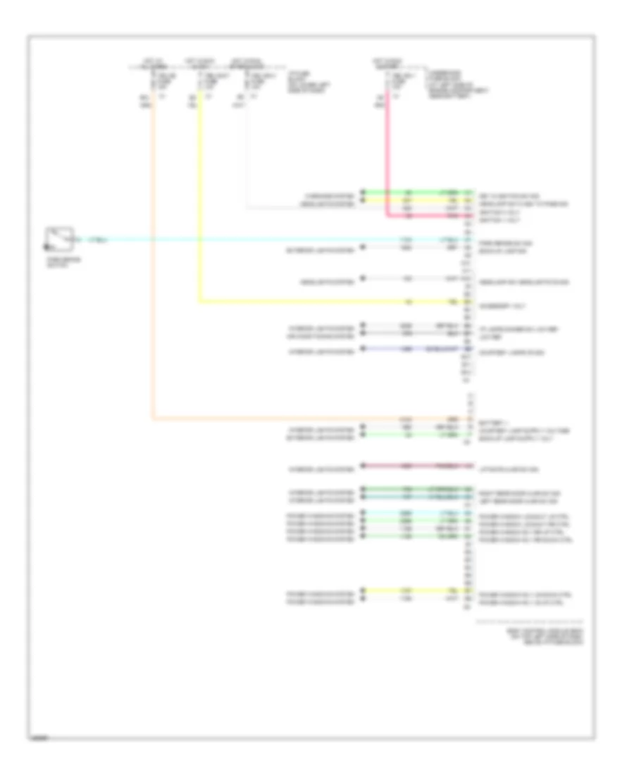
Compressor Wiring Diagram for Hummer H2 2007
 https://portal-diagnostov.com/license.html
Automotive Electricians Portal FZCO
Automotive Electricians Portal FZCO
https://portal-diagnostov.com/license.html
https://portal-diagnostov.com/license.html
Automotive Electricians Portal FZCO
Automotive Electricians Portal FZCOList of elements for Compressor Wiring Diagram for Hummer H2 2007:
- 5v ref
- A/c comp cl rly ctrl
- A/c comp fuse 10a
- A/c compressor clutch
- A/c compressor clutch relay
- A/c low pressure switch (right side of accumulator)
- A/c on switch
- A/c ref pre sens sig
- A/c refrigerant pressure sensor (in rear of a/c compressor)
- A12
- B11
- Class 2 ser data
- Class 2 serial data
- G104 (on top left rear of engine)
- Hot at all times
- Hot in run or start
- Hvac control module (behind center of dash)
- Ign e fuse 10a
- Lo press sens sig
- Logic
- Low ref
- Powertrain control module (left front of engine compt)
- S102 (in engine harn, 4 cm from knock sensor connector)
- Sp205 (on left side of dash)
- Underhood fuse block (left side of engine compt, near battery)
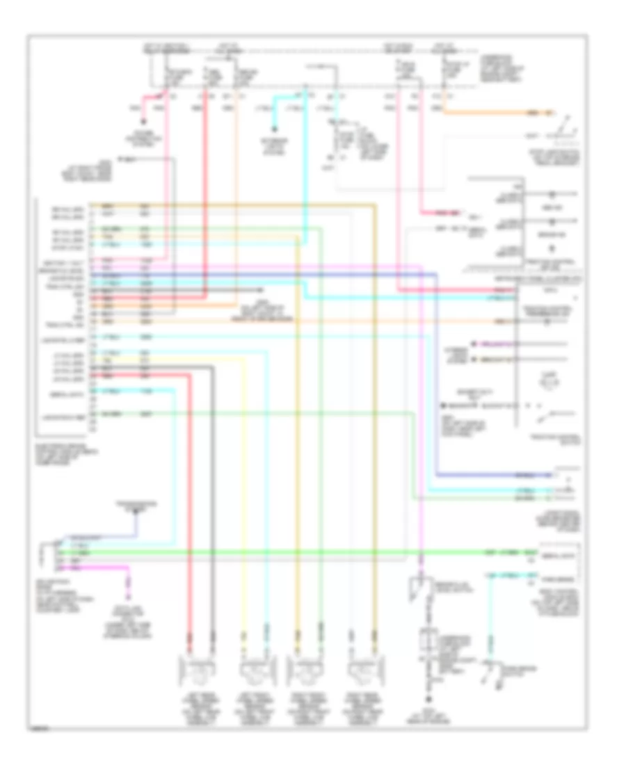
ANTI-LOCK BRAKES
Anti-lock Brakes Wiring Diagram for Hummer H2 2007
 https://portal-diagnostov.com/license.html
Automotive Electricians Portal FZCO
Automotive Electricians Portal FZCO
https://portal-diagnostov.com/license.html
https://portal-diagnostov.com/license.html
Automotive Electricians Portal FZCO
Automotive Electricians Portal FZCOList of elements for Anti-lock Brakes Wiring Diagram for Hummer H2 2007:
- (except sut) s217
- Abs fuse 60a
- Abs ind
- B12
- Body control module (bcm) (on top left side of dash, above i/p fuse block)
- Brake fld level
- Brake fluid level switch
- Brake ind
- C1 e7
- C2 b7
- Class 2 ser data
- D10
- Data link connector (dlc) (under left side of dash, below steering column)
- E11
- Electronic brake control module (ebcm) (on left side of inner frame)
- Etc/ecm fuse 15a
- Exterior lights system
- F pnk
- F12
- G104 (at top left rear of engine)
- G200 (on left side of dash, near left kick panel)
- G300 (on left side of body mount, in front of driver door)
- G403 (at right frame body mount, near right rear door)
- Gnd
- Hot at all times
- Hot in run or start
- Hot w/ ignition 1 relay energized
- I/p fuse block (on lower left side of dash)
- Ign
- Ign 1
- Ign e fuse 10a
- Ignition 1 volt
- Illum
- Instrument panel cluster (ipc)
- Interior lights system
- Left front wheel speed sensor (on left front wheel hub assembly)
- Left rear wheel speed sensor (on left rear wheel hub assembly)
- Lf whl spd
- Lng rate 5v ref
- Lng rate lo ref
- Lng rate sig
- Longitudinal accelerometer (behind center of dash)
- Lr whl spd
- On left side of dash, near footwell courtesy lamp)
- Park brake
- Park brake switch
- Pnk
- Power distribution system
- Red
- Rf whl spd
- Right front wheel speed sensor (on right front wheel hub assembly)
- Right rear wheel speed sensor (on right rear wheel hub assembly)
- Rr whl spd
- S102
- Seo b2 fuse 30a
- Serial data
- Splice pack sp205 (in i/p harness,
- Stop fuse 15a
- Stop lamp switch (on top of brake pedal bracket)
- Stop lp fuse 25a
- Stop lp sw
- Tan
- Trac ctrl ind
- Trac ctrl sig
- Traction control off ind
- Traction control preference ind
- Traction control switch
- Transmissions system
- Underhood fuse block (at left side of engine compt, near battery)
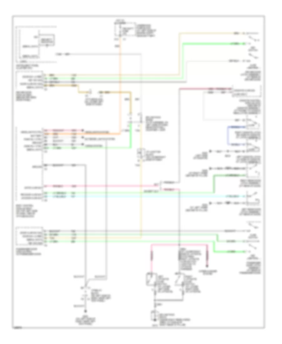
ANTI-THEFT
Forced Entry Wiring Diagram for Hummer H2 2007
 https://portal-diagnostov.com/license.html
Automotive Electricians Portal FZCO
Automotive Electricians Portal FZCO
https://portal-diagnostov.com/license.html
https://portal-diagnostov.com/license.html
Automotive Electricians Portal FZCO
Automotive Electricians Portal FZCOList of elements for Forced Entry Wiring Diagram for Hummer H2 2007:
- A12
- Ajar
- Ajar input
- Ajar switch
- B12
- Battery
- Body control module (bcm) (on top left side of dash, above i/p fuse block)
- D12
- Door ajar sw sig
- Door sw lo ref
- Driver door latch assembly (at rear of driver door)
- Driver door module (ddm) (behind driver's door panel)
- Except sut
- Exterior lights system
- G200 (on left side of dash, near left kick panel)
- G302 (at left inner center "b" pillar)
- G306 (at right inner center "b" pillar)
- G320 (left side of midgate)
- G410
- Gate ajar sw
- Ground
- Headlights ctrl
- Headlights system
- Horn rly ctrl
- Horns system
- Hot at all times
- I/p fuse block (on lower left side of dash)
- I/p junction block (on lower right side of dash) c7
- I/p relay block (on left side of dash, near left kick panel)
- Ign
- Instrument panel cluster (ipc)
- Key sw sig
- Key switch
- Left liftgate ajar switch (at lower left side of liftgate)
- Left midgate latch (lh side of midgate, at latch assembly)
- Left rear door latch assembly (at rear of door)
- Logic
- Lr door ajar sw
- Midgate ajar sig
- Midgate control module (mcm) (center of midgate assembly, attached to window regulator assembly)
- Park rly ctrl
- Passenger door latch assembly (at rear of passenger door)
- Passenger door module (pdm) (in passenger door)
- Right liftgate ajar switch (at lower right side of liftgate)
- Right midgate latch (rh side of midgate, at latch assembly)
- Right rear door latch assembly (at rear of door)
- Rr door ajar sw
- S310
- S339
- S390
- S901
- S902 (at lower right side of liftgate, 6.5 cm from right liftgate ajar switch junction to liftgate harness)
- Security indicator
- Serial data
- Splice pack sp205 (in i/p harness, on left side of dash, near footwell courtesy lamp)
- Splice pack sp410 (inside right rear cargo area, at middle of right rear "d" pillar)
- Sut
- Tan
- Tbc batt fuse 10a
- Underhood fuse block (at left side of engine compt, near battery)
- Wiper/washer system
Passlock Wiring Diagram for Hummer H2 2007
 https://portal-diagnostov.com/license.html
Automotive Electricians Portal FZCO
Automotive Electricians Portal FZCO
https://portal-diagnostov.com/license.html
https://portal-diagnostov.com/license.html
Automotive Electricians Portal FZCO
Automotive Electricians Portal FZCOList of elements for Passlock Wiring Diagram for Hummer H2 2007:
- (at left side of engine)
- (at right side of engine)
- 12v ref
- A11
- A12
- B12
- Battery
- Body control module (bcm) (on top left side of dash, above i/p fuse block)
- Connector (dlc) (under left side of dash, below steering column)
- D12
- Data link
- Fuel injector 1
- Fuel injector 2
- Fuel injector 3
- Fuel injector 4
- Fuel injector 5
- Fuel injector 6
- Fuel injector 7
- Fuel injector 8
- G200 (on left side of dash, near left kick panel)
- Ground
- Hot at all times
- Hot in run & start
- I/p relay block (on left side of dash, near left kick panel)
- Ign
- Ign 1 volt
- Inj 1 ctrl
- Inj 2 ctrl
- Inj 3 ctrl
- Inj 4 ctrl
- Inj 5 ctrl
- Inj 6 ctrl
- Inj 7 ctrl
- Inj 8 ctrl
- Instrument panel cluster (ipc)
- Logic
- Low ref
- Passlock electronics
- Passlock sensor (part of ignition lock cylinder, in steering column assembly)
- Pnk
- Powertrain control module (pcm) (on left front of engine compt)
- Sec sens sig
- Security indicator
- Serial data
- Splice pack sp205 (in i/p harness, on left side of dash, near footwell courtesy lamp)
- Tbc batt fuse 10a
- Tbc ign 1 fuse 10a
- Underhood fuse block (at left side of engine compt, near battery)
BODY CONTROL MODULES
Body Control Modules Wiring Diagram (1 of 2) for Hummer H2 2007
 https://portal-diagnostov.com/license.html
Automotive Electricians Portal FZCO
Automotive Electricians Portal FZCO
https://portal-diagnostov.com/license.html
https://portal-diagnostov.com/license.html
Automotive Electricians Portal FZCO
Automotive Electricians Portal FZCOList of elements for Body Control Modules Wiring Diagram (1 of 2) for Hummer H2 2007:
- 12 volt ref
- 5v ref
- A10
- A11
- A12
- Air conditioning system
- Ambient light sens sig
- Anti-theft system
- B10
- B11
- B12
- Battery +
- Bcm class 2 serial data
- Body control module (bcm) (on top left side of dash, above i/p fuse block)
- Class 2 serial data
- Computer data lines system
- D12
- Defogger system
- Dimming input sig
- Door locks system
- Driver sunload sens sig
- Drl off ind ctrl
- Drl relay ctrl
- Drl sw sig
- E11
- E12
- Exterior lights system
- G200 (on left side of dash, near left kick panel)
- Ground
- Headlamp dimmer sw sig
- Headlamp high beam relay ctrl
- Headlamp low beam relay ctrl
- Headlamp on ind ctrl
- Headlights system
- Horn rly ctrl
- Horns system
- Hot at all times
- I/p fuse block (on lower left side of dash)
- I/p lamp dimming ctrl
- I/p relay block (on left side of dash, near left kick panel)
- Interior lamp defeat sw sig
- Interior lights system
- Led dimming sig
- Lift gate lock relay
- Park lamp relay ctrl
- Park lamp sw on sig
- Passenger sunload sens sig
- Pnk
- Power tops system
- Rear defog rly ctrl
- Rear door lock rly ctrl
- Rear door unlock rly ctrl
- Red
- Remote radio ctrl sig
- Security system sens low ref
- Security system sens sig
- Sound system
- Tbc 2a fuse 15a
- Tbc 2c fuse 15a
- Tbc batt fuse 10a
- Tow/haul sw sig
- Transmissions system
- Underhood fuse block (at left side of engine compartment, near battery)
- Windshield wiper sw sig 2
Body Control Modules Wiring Diagram (2 of 2) for Hummer H2 2007
 https://portal-diagnostov.com/license.html
Automotive Electricians Portal FZCO
Automotive Electricians Portal FZCO
https://portal-diagnostov.com/license.html
https://portal-diagnostov.com/license.html
Automotive Electricians Portal FZCO
Automotive Electricians Portal FZCOList of elements for Body Control Modules Wiring Diagram (2 of 2) for Hummer H2 2007:
- A10
- A11
- Accessory volt
- Air conditioning system
- B10
- B11
- B12
- Back-up lamp sig
- Battery +
- Body control module (bcm) (on top left side of dash, above i/p fuse block)
- Courtesy lamps on sig
- Exterior lights system
- Headlamp sw flash to pass sig
- Headlamp sw headlights on sig
- Headlights system
- Hot at all times
- Hot in run & acc
- Hot in run & start
- Hot in run, start & acc
- I/p fuse block (on lower left side of dash)
- I/p lamps dimmer sw low ref
- Ignition 0 volt
- Ignition 1 volt
- Interior lights system
- Key in ignition sw sig
- Left rear door ajar sw sig
- Liftgate ajar sw sig
- Low ref
- Park brake sw sig
- Park brake switch
- Pnk
- Power window lockout lr ctrl
- Power window lockout rr ctrl
- Power window rly lr down ctrl
- Power window rly lr up ctrl
- Power window rly rr down ctrl
- Power window rly rr up ctrl
- Power windows system
- Right rear door ajar sw sig
- Tbc 2b fuse 15a
- Tbc accy fuse 10a
- Tbc ign 0 fuse 10a
- Tbc ign 1 fuse 10a
- Underhood fuse block (at left side of engine compartment, near battery)
- Warnings system
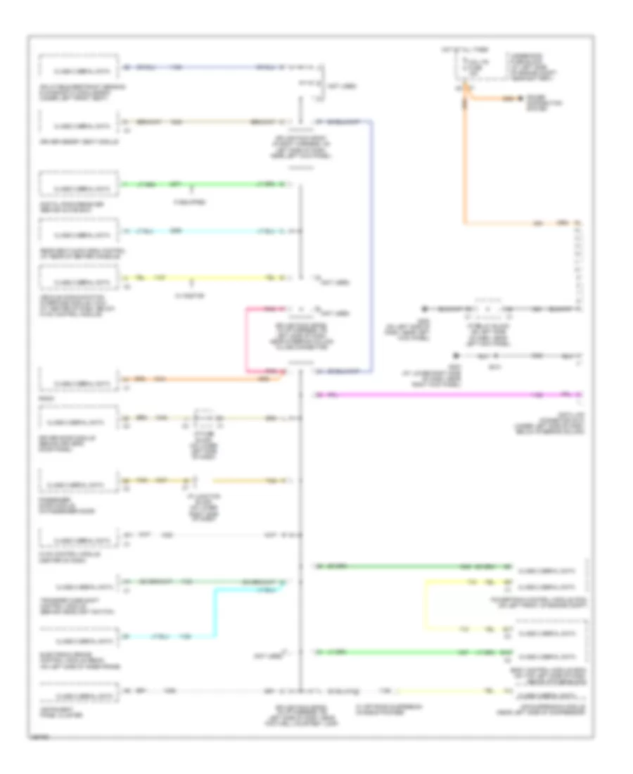
COMPUTER DATA LINES
Computer Data Lines Wiring Diagram for Hummer H2 2007
 https://portal-diagnostov.com/license.html
Automotive Electricians Portal FZCO
Automotive Electricians Portal FZCO
https://portal-diagnostov.com/license.html
https://portal-diagnostov.com/license.html
Automotive Electricians Portal FZCO
Automotive Electricians Portal FZCOList of elements for Computer Data Lines Wiring Diagram for Hummer H2 2007:
- (not used)
- A (not used)
- Air suspension module (near left side of compressor)
- B11
- B12
- Body control module (bcm) (on top left side of dash, above i/p fuse block)
- Cig ltr fuse 15a
- Class 2 serial data
- D (not used)
- Data link connector (dlc) (under left side of dash, below steering column)
- Digital radio receiver (behind glove box)
- Driver door module (behind driver's door panel)
- Driver memory seat module
- Electronic brake control module (ebcm) (on left side of inner frame)
- G200 (on left side of dash, near left kick panel)
- G203 (at lower right side of dash, near right kick panel)
- Hot at all times
- Hvac control module (center of dash)
- I/p fuse block (on lower left side of dash)
- I/p junction block (on lower right side of dash)
- I/p relay block (on left side of dash, near left kick panel)
- If equipped
- Inflatable restraint sensing & diagnostic module(sdm) (under left front seat)
- Instrument panel cluster
- K (not used)
- Passenger door module (in passenger door)
- Pnk
- Power distribution system
- Powertrain control module (pcm) (on left front of engine compt)
- Radio
- Rear seat audio (rsa) control (at rear of center console)
- S213
- Splice pack sp205 (in i/p harness, on left side of dash, near footwell courtesy lamp)
- Splice pack sp206 (in i/p harness, on left side of dash, near steering column in-line connector)
- Splice pack sp207 (in body harness, on left side of dash, near left kick panel)
- Tan
- Transfer case shift control module (behind headlight switch)
- Underhood fuse block (at left side of engine compt, near battery)
- Vehicle communication interface module (vcim) (at center of dash, below hvac control module)
- W/ off road suspension chassis package
- W/ onstar
CRUISE CONTROL
Cruise Control Wiring Diagram for Hummer H2 2007
 https://portal-diagnostov.com/license.html
Automotive Electricians Portal FZCO
Automotive Electricians Portal FZCO
https://portal-diagnostov.com/license.html
https://portal-diagnostov.com/license.html
Automotive Electricians Portal FZCO
Automotive Electricians Portal FZCOList of elements for Cruise Control Wiring Diagram for Hummer H2 2007:
- 5v ref
- Accelerator pedal position sensor (below left side of dash)
- App sensor 1 sig
- App sensor 2 sig
- C2 a10
- Class 2 data
- Computer data lines system
- Cruise control on/off switch
- Cruise fuse 10a
- Cruise ind
- Cruise on sw sig
- Etc/ecm fuse 15a
- F12
- G104 (at top left rear of engine)
- Ground
- Hot at all times
- Hot in run
- Hot in run or start
- I/p fuse block (on lower left side of dash)
- Ign
- Ign volt
- Instrument panel cluster (ipc)
- Logic
- Low ref
- Nca
- On/off
- Pnk
- Power distribution system
- Powertrain control module (pcm) (on left front of engine compt)
- Resume/ accel
- Resume/accel sig
- S102
- Serial data
- Set/ coast
- Set/coast sig
- Stop lamp switch (on top of brake pedal bracket)
- Stop lp fuse 25a
- Tac motor cntrl 1
- Tac motor cntrl 2
- Tan
- Throttle actuator control (tac) module (at left rear of engine compt)
- Throttle body (top of engine, mounted to front of intake manifold)
- Tp sensor 1 sig
- Tp sensor 2 sig
- Turn signal/ multifunction switch
- Under- hood fuse block (at left side of engine compt, near battery)
- Underhood fuse block (at left side of engine compt, near battery)
- Veh stop fuse 15a
- Vehicle speed sensor (vss) (on rear of transfer case assembly)
- Vss high
- Vss low
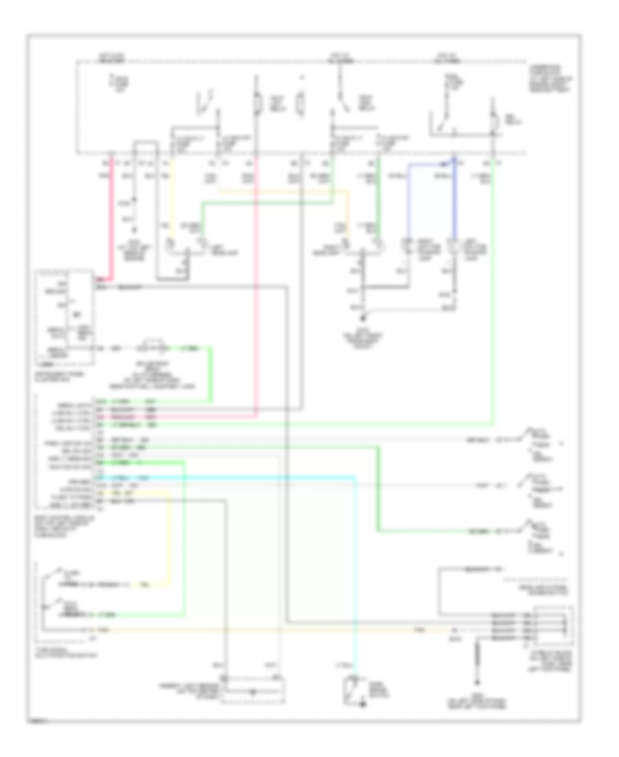
DEFOGGERS
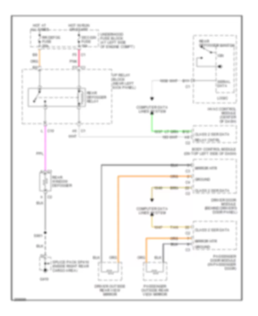
Defoggers Wiring Diagram, Except SUT for Hummer H2 2007
 https://portal-diagnostov.com/license.html
Automotive Electricians Portal FZCO
Automotive Electricians Portal FZCO
https://portal-diagnostov.com/license.html
https://portal-diagnostov.com/license.html
Automotive Electricians Portal FZCO
Automotive Electricians Portal FZCOList of elements for Defoggers Wiring Diagram, Except SUT for Hummer H2 2007:
- A c1
- A c2
- A6 c1
- B11
- B12
- Body control module (on top left side of dash)
- C1 f3
- C1 f5
- Class 2 ser data
- Computer data lines system
- Driver door module (behind driver's door panel)
- Driver outside rear view mirror
- G410
- Ground
- Hot at all times
- Hot in run or start
- Hvac control module (center of dash)
- I/p relay block (near left kick panel)
- Ign
- L c10
- Logic
- Mirror htr
- Passenger door module (in passenger door)
- Passenger outside rear view mirror
- Pnk
- Rear defogger relay
- Rear defogger switch
- Rear window defogger
- Relay cntrl
- Rr defog fuse 30a
- S901
- Seo ign fuse 10a
- Serial data
- Splice pack sp410 (inside right rear cargo area)
- Tan
- Underhood fuse block (at left side of engine compt)
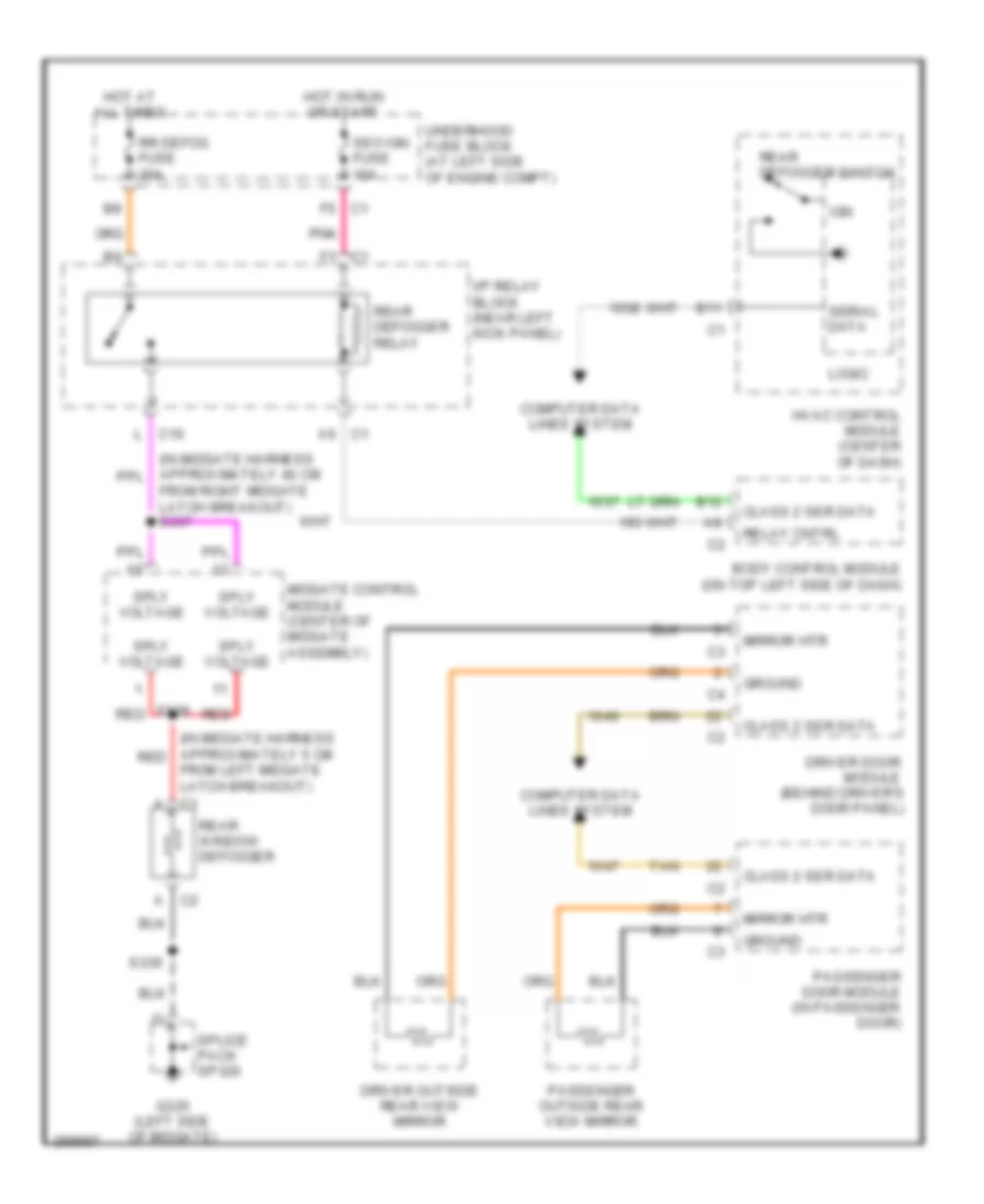
Defoggers Wiring Diagram, SUT for Hummer H2 2007
 https://portal-diagnostov.com/license.html
Automotive Electricians Portal FZCO
Automotive Electricians Portal FZCO
https://portal-diagnostov.com/license.html
https://portal-diagnostov.com/license.html
Automotive Electricians Portal FZCO
Automotive Electricians Portal FZCOList of elements for Defoggers Wiring Diagram, SUT for Hummer H2 2007:
- (in midgate harness approximately 5 cm red
- A c2
- A6 c1
- B11
- B12
- Body control module (on top left side of dash)
- C1 f3
- C1 f5
- Class 2 ser data
- Computer data lines system
- Driver door module (behind driver's door panel)
- Driver outside rear view mirror
- From left midgate latch breakout) c1
- From right midgate latch breakout) s337
- G320 (left side of midgate)
- Ground
- Hot at all times
- Hot in run or start
- Hvac control module (center of dash)
- I/p relay block (near left kick panel)
- Ign
- L c10
- Logic
- Midgate control module (center of midgate assembly)
- Mirror htr
- Passenger door module (in passenger door)
- Passenger outside rear view mirror
- Pnk
- Rear defogger relay
- Rear defogger switch
- Rear window defogger
- Red
- Relay cntrl
- Rr defog fuse 30a
- S338 red
- S339
- Seo ign fuse 10a
- Serial data
- Splice pack sp320
- Sply voltage
- Tan
- Underhood fuse block (at left side of engine compt)
ELECTRONIC SUSPENSION
Electronic Suspension Wiring Diagram for Hummer H2 2007
 https://portal-diagnostov.com/license.html
Automotive Electricians Portal FZCO
Automotive Electricians Portal FZCO
https://portal-diagnostov.com/license.html
https://portal-diagnostov.com/license.html
Automotive Electricians Portal FZCO
Automotive Electricians Portal FZCOList of elements for Electronic Suspension Wiring Diagram for Hummer H2 2007:
- (at rear underside of vehicle, in air suspension suspension harness)
- (at right rear frame body mount) g405
- (in air suspension harness at rear underside of vehicle) s407
- (in air suspension harness at rear underside of vehicle) s408
- (in chassis harness, at right rear frame rail, 15 cm from junction of right rear air suspension sensor to chassis harness) s400
- (in chassis harness, at right rear frame rail, 30 cm from junction of right rear air suspension sensor to chassis harness)
- 4wd fuse 15a
- 5 volt ref
- Air susp exhaust valve ctrl
- Air susp press sens sig
- Air susp rly ctrl
- Air suspension compressor 1
- Air suspension compressor 2
- Air suspension exhaust valve (attached to right side of compressor head)
- Air suspension inflator switch (near right "d" pillar)
- Air suspension module (near left side of compressor)
- Air suspension pressure sensor (at left side of compressor)
- Batt+
- C-rly
- Class 2 serial data
- Computer data lines system
- Coone
- Cotwo
- Dummy
- E-bat
- E-gnd
- Electronically controlled air suspension relay (near lower side of left front wheelwell)
- Erh-led
- Erh-sw
- G203 (at lower right side of dash, near right kick panel)
- G402 (attached to front of air suspension mounting bracket)
- Ground
- Hot at all times
- Hot in run
- Hs-gnd
- Hs-one
- Hs-two
- Hs/pt1
- Hvac/ ecas fuse 10a
- I/p fuse block (on lower left side of dash)
- Ign
- Ign 3 volt
- Inf-gnd
- Inf-sw
- Inf/led
- Inflator sw ind ctrl
- Inflator sw lo ref
- Inflator sw sig
- Interior lights system
- J1850
- Left rear air suspension inlet valve (near right front of compressor)
- Left rear air suspension sensor (at left rear frame rail, attached to top of frame)
- Lo ref
- Low ref
- Lr air susp sens sig
- Lr air susp valve ctrl
- Nca
- Overtemp sig
- P-t
- Power windows system
- Pt-gnd
- Red
- Ride height active ind
- Ride height sw sig
- Ride height switch
- Right rear air suspension inlet valve (near right front of compressor)
- Right rear air suspension sensor (at right rear frame rail, attached to top of frame)
- Rr air susp sen sig
- Rr air susp valve ctrl
- S-one
- S-two
- S215
- S401
- S409 (in air suspension harness at rear underside of vehicle)
- S414
- Underhood fuse block (at left side of engine compt, near battery)
- Underside of vehicle)
- V-one
- V-seven
- V-two
- Vses/ ecas fuse 60a
ENGINE PERFORMANCE
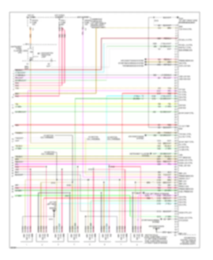
6.0L VIN U
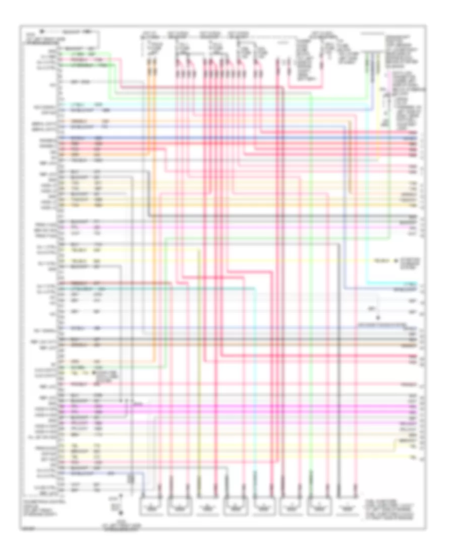
6.0L VIN U, Engine Performance Wiring Diagram (1 of 5) for Hummer H2 2007
 https://portal-diagnostov.com/license.html
Automotive Electricians Portal FZCO
Automotive Electricians Portal FZCO
https://portal-diagnostov.com/license.html
https://portal-diagnostov.com/license.html
Automotive Electricians Portal FZCO
Automotive Electricians Portal FZCOList of elements for 6.0L VIN U, Engine Performance Wiring Diagram (1 of 5) for Hummer H2 2007:
- +5v
- 12 v ref
- 3-2 ss ctrl
- Air conditioning system
- Brk sw sig
- C10
- Ckp sig
- Cls 2 data
- Cmp sig
- Computer data lines system
- Crankshaft position (ckp) sensor (at lower right rear side of engine block, behind starter solenoid)
- D10
- Data link connector (under left side of dash, below steering column)
- E10
- Ect sig
- F10
- Fuel injectors (fuel injectors 1,3,5 & 7: at left side of engine) (fuel injectors 2,4,6 & 8: at right side of engine)
- G102 (at left front side of engine block)
- Gnd
- Ho2s hi sig
- Ho2s lo
- Hot at all times
- Hot in acc, run or start
- Hot in run or start
- I/p fuse block (on lower left side of dash)
- Ign
- Ign 0 fuse 10a
- Inj 1 ctrl
- Inj 1 fuse 15a
- Inj 2 ctrl
- Inj 2 fuse 15a
- Inj 3 ctrl
- Inj 4 ctrl
- Inj 5 ctrl
- Inj 6 ctrl
- Inj 7 ctrl
- Inj 8 ctrl
- Ks 1 signal
- Ks 2 signal
- O2a fuse 15a
- O2b fuse 15a
- Oil lev sw sig
- Pcm b fuse 20a
- Pnk
- Pnk a
- Powertrain control module (on left front of engine compt)
- Prnd a sig
- Prnd b sig
- Prnd p sig
- Range b
- Range c
- Red
- Ref low
- Ref low (a/t)
- Rly ctrl
- S103
- S104
- Serial data
- Sp205 (in i/p harness, on left side of dash, near footwell courtesy lamp)
- Starting/ charging system
- Tan
- Under- hood fuse block (at left side of engine compt, near battery)
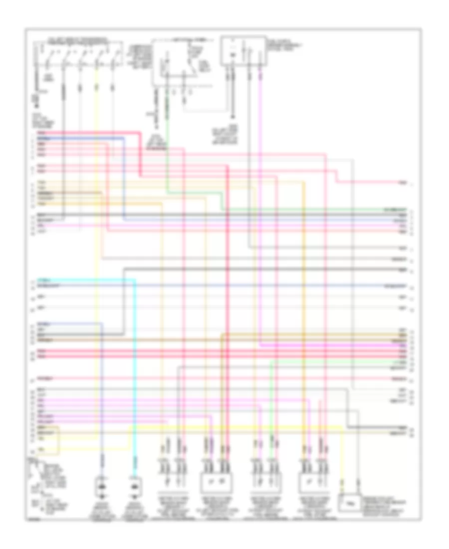
6.0L VIN U, Engine Performance Wiring Diagram (2 of 5) for Hummer H2 2007
 https://portal-diagnostov.com/license.html
Automotive Electricians Portal FZCO
Automotive Electricians Portal FZCO
https://portal-diagnostov.com/license.html
https://portal-diagnostov.com/license.html
Automotive Electricians Portal FZCO
Automotive Electricians Portal FZCOList of elements for 6.0L VIN U, Engine Performance Wiring Diagram (2 of 5) for Hummer H2 2007:
- (at top right rear of engine) g103
- (not used)
- (on left side of transmission) park/neutral position switch
- Engine coolant temperature sensor (near rear of engine block, below exhaust manifold)
- Engine oil level switch (on lower right side of oil pan)
- Fuel pump & sender assembly (in fuel tank)
- Fuel pump relay
- G103 (at top right rear of engine)
- G104 (at top left rear of engine)
- G300 (on left side body mount, in front of driver door)
- Heated oxygen sensor (bank 1 sensor 1) (in left exhaust pipe, before catalytic converter)
- Heated oxygen sensor (bank 1 sensor 2) (in left exhaust pipe, after catalytic converter)
- Heated oxygen sensor (bank 2 sensor 1) (in right exhaust pipe, before catalytic converter)
- Heated oxygen sensor (bank 2 sensor 2) (in right exhaust pipe, after catalytic converter)
- Hot at all times
- Knock sensor 1 (in valley, under intake manifold)
- Knock sensor 2 (in valley, under intake manifold)
- Nca
- Pcm b fuse 20a
- Pnk
- Red
- S103
- Tan
- Underhood fuse block (at left side of engine compt, near battery)
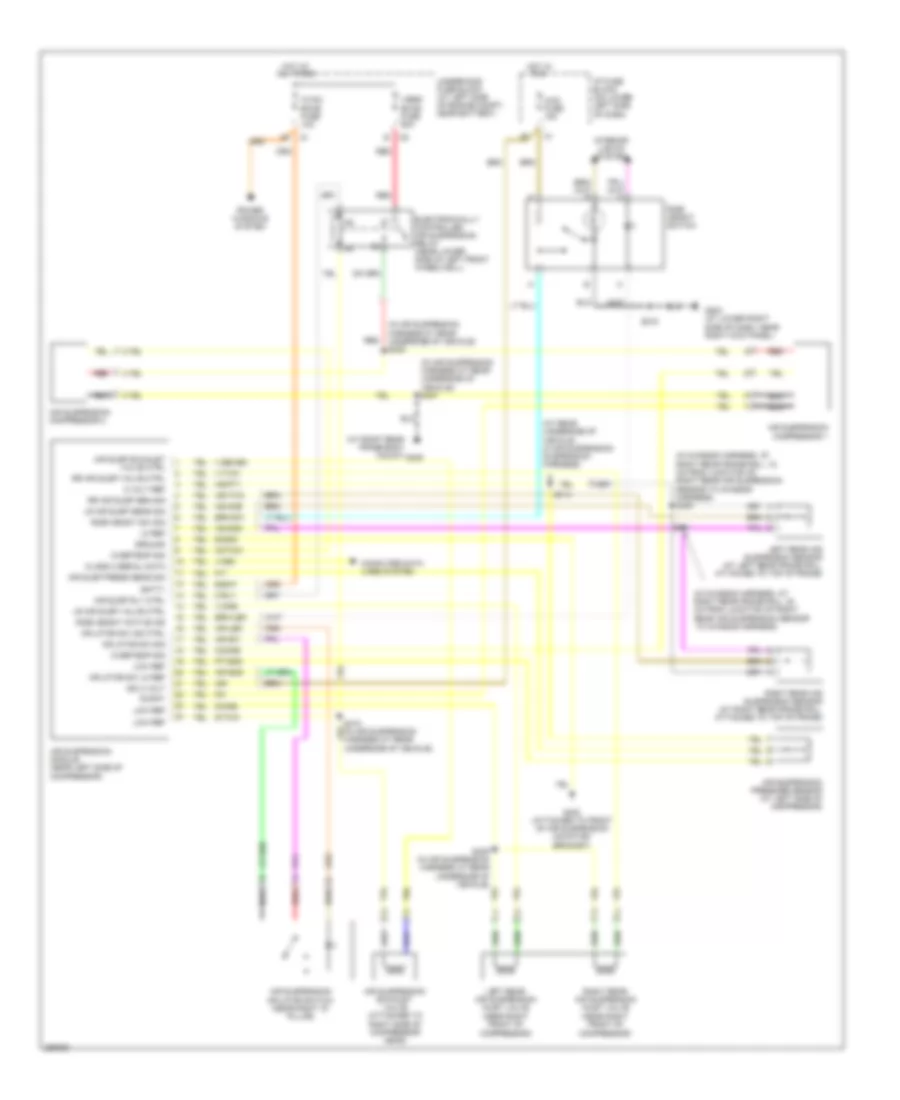
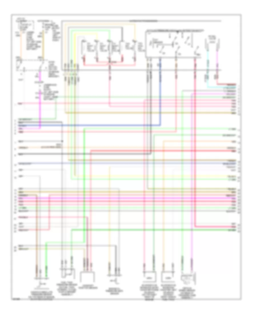
6.0L VIN U, Engine Performance Wiring Diagram (3 of 5) for Hummer H2 2007
 https://portal-diagnostov.com/license.html
Automotive Electricians Portal FZCO
Automotive Electricians Portal FZCO
https://portal-diagnostov.com/license.html
https://portal-diagnostov.com/license.html
Automotive Electricians Portal FZCO
Automotive Electricians Portal FZCOList of elements for 6.0L VIN U, Engine Performance Wiring Diagram (3 of 5) for Hummer H2 2007:
- 1-2 shift sol valve
- 2-3 shift sol valve
- 3-2 shift sol valve
- A red
- A/t fluid pressure manual valve position switch
- Automatic transmission
- B red
- Brake fuse 10a
- C12
- C2 c12
- Camshaft position sensor
- Engine oil pressure (eop) sensor
- Evaporative emissions (evap) canister purge solenoid (on top right front of engine)
- Evaporative emissions canister vent solenoid (on right front side of fuel tank)
- F12
- Fuel tank pressure sensor (on fuel tank, integral to fuel pump & sender assembly)
- Hot at all times
- Hot in run
- I/p fuse block (on lower left side of dash)
- Manifold absolute pressure sensor (on top rear of engine, on intake manifold)
- N pnk
- P red
- Pc sol valve
- Pnk
- Pnk a
- Red
- Red/
- Rev
- S125
- S304 (21.5 cm from g300)
- Stop lp fuse 25a
- Stop- lamp switch (on top of brake pedal bracket)
- Tan
- Tcc pwm sol valve
- Tcc sol valve
- Tft sensor
- Under- hood fuse block (at left side of engine compt, near battery)
- Underhood fuse block (at left side of engine compt, near battery)
- Vehicle speed sensor (on rear of transfer case assembly)
6.0L VIN U, Engine Performance Wiring Diagram (4 of 5) for Hummer H2 2007
 https://portal-diagnostov.com/license.html
Automotive Electricians Portal FZCO
Automotive Electricians Portal FZCO
https://portal-diagnostov.com/license.html
https://portal-diagnostov.com/license.html
Automotive Electricians Portal FZCO
Automotive Electricians Portal FZCOList of elements for 6.0L VIN U, Engine Performance Wiring Diagram (4 of 5) for Hummer H2 2007:
- 4ws fuse 15a
- A10 c2
- Accelerator pedal position sensor (below left side of dash)
- App sens 1
- App sens 2
- Close
- Cruise control system
- Cruise req
- Data
- Etc/ecm fuse 15a
- F10 c2
- G103 (at top right rear of engine)
- G104 (at top left rear of engine)
- Gnd
- Ground
- Hot at all times
- Hot in acc, run or start
- Hot in run or start
- I/p fuse block (on lower left side of dash)
- Iat sensor
- Ign
- Ign 0 fuse 10a
- Intake air temperature (iat)/ mass air flow (maf) sensor (in air induction tube)
- Open
- Pnk
- R/a input
- Red
- Ref low
- S/c input
- S102
- S103
- Sig
- Stop fuse 15a
- Stp lp in
- Tac ctrl
- Tan
- Throttle actuator control module (at left rear of engine compt)
- Throttle body (top of engine, mounted to front of intake manifold)
- Tp sens 1
- Tp sens 2
- Underhood fuse block (at left side of engine compt, near battery)
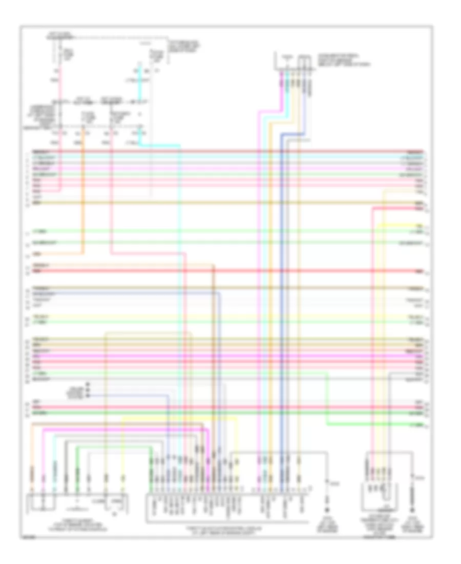
6.0L VIN U, Engine Performance Wiring Diagram (5 of 5) for Hummer H2 2007
 https://portal-diagnostov.com/license.html
Automotive Electricians Portal FZCO
Automotive Electricians Portal FZCO
https://portal-diagnostov.com/license.html
https://portal-diagnostov.com/license.html
Automotive Electricians Portal FZCO
Automotive Electricians Portal FZCOList of elements for 6.0L VIN U, Engine Performance Wiring Diagram (5 of 5) for Hummer H2 2007:
- (at top left rear of engine) g104
- (in ignition coil harness)
- (top left rear of engine) g104
- 1-2 ss ctrl
- 12 volt ref
- 2-3 ss ctrl
- 4wd low sig
- A12
- Air conditioning system
- B10
- B11
- Clu rly ctrl
- Crank fuse 10a
- Crank volt
- Ctrl
- Cycle sig
- Eng speed sig
- Evap canp ctrl
- Evap vent ctrl
- Fuel lev sig
- Fuel press sig
- G102 (at left front side of engine block)
- Gnd
- Ho2s htr low
- Ho2s low ctrl
- Hot at all times
- Hot in run & start
- Hot in start
- Iat sig
- Ic1 ctrl
- Ic2 ctrl
- Ic3 ctrl
- Ic4 ctrl
- Ic5 ctrl
- Ic6 ctrl
- Ic7 ctrl
- Ic8 ctrl
- Ign
- Ignition coils (fuel injectors 1,3,5 & 7: at left side of engine) (fuel injectors 2,4,6 & 8: at right side of engine)
- Ind ctrl
- Instrument cluster system
- Instrument panel cluster (ipc)
- Ipc sig
- Ipc/dic fuse 10a
- Logic
- Maf sig
- Malfunction indicator lamp
- Map sig
- Mil ctrl
- Pc sol hi ctrl
- Pc sol lo ctrl
- Pcm 1 fuse 15a
- Pmp rly ctrl
- Pnk
- Pnk d
- Powertrain control module (on left front of engine compt)
- Press sens sig
- Prnd c sig
- Red
- Red c
- Ref lo
- Ref low
- S103
- S140
- S141
- S142
- S160
- S161
- S162
- Starting/charging system
- Tan
- Tcc pwm ctrl
- Tcc sol ctrl
- Tft sens sig
- Transmissions system
- Underhood fuse block (at left side of engine compt, near battery)
- Vss
- Vss high sig
- Vss low sig
EXTERIOR LIGHTS
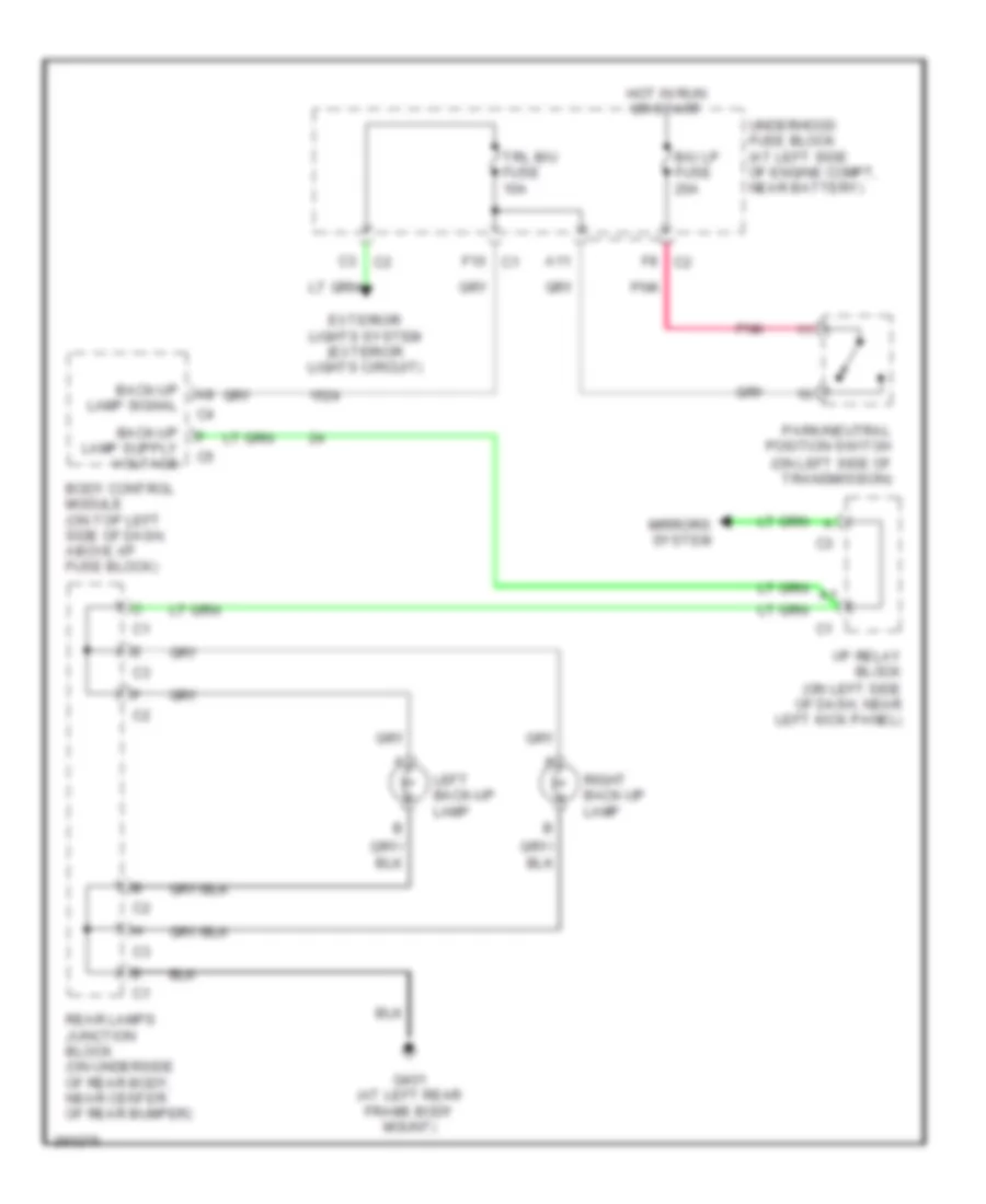
Back-up Lamps Wiring Diagram for Hummer H2 2007
 https://portal-diagnostov.com/license.html
Automotive Electricians Portal FZCO
Automotive Electricians Portal FZCO
https://portal-diagnostov.com/license.html
https://portal-diagnostov.com/license.html
Automotive Electricians Portal FZCO
Automotive Electricians Portal FZCOList of elements for Back-up Lamps Wiring Diagram for Hummer H2 2007:
- (on left side of dash, near left kick panel)
- (on left side of transmission)
- A11
- B/u lp fuse 20a
- Back-up lamp signal
- Body control module (on top left side of dash, above i/p fuse block)
- C3 c2
- Exterior lights system (exterior lights circuit)
- F10 c1
- F8 c2
- G401 (at left rear frame body mount)
- Hot in run or start
- I/p relay block
- Left back-up lamp
- Mirrors system
- Park/neutral position switch
- Pnk
- Rear lamps junction block (on underside of rear body, near center of rear bumper)
- Right back-up lamp
- Trl b/u fuse 10a
- Underhood fuse block (at left side of engine compt, near battery)
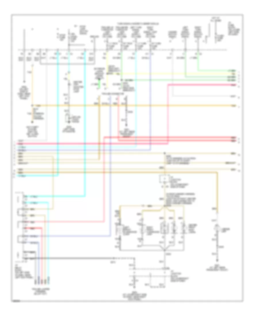
Exterior Lamps Wiring Diagram, SUT (1 of 3) for Hummer H2 2007
 https://portal-diagnostov.com/license.html
Automotive Electricians Portal FZCO
Automotive Electricians Portal FZCO
https://portal-diagnostov.com/license.html
https://portal-diagnostov.com/license.html
Automotive Electricians Portal FZCO
Automotive Electricians Portal FZCOList of elements for Exterior Lamps Wiring Diagram, SUT (1 of 3) for Hummer H2 2007:
- (in i/p harn, 8.5 cm from junction of instr- ument cluster conn harness to i/p harn)
- (on left side of dash, near left kick panel)
- A10
- A12
- Auto
- Body control module (on top left side of dash, above i/p fuse block)
- C2 d
- C3 b
- C5 i/p relay block
- Class 2 serial data
- D10
- Differe- ntial lock actuator)
- Drl defeat
- E c1
- E10
- Electronic brake control module (on left side of inner frame)
- F c3
- F11
- F12
- Frt park fuse 10a
- G100 (on left front frame body mount)
- G200 (on left side of dash, near left kick panel)
- G401 (at left rear frame body mount)
- H c2
- Head
- Headlamp & panel dimmer switch
- Hot at all times
- Hot in run or start
- Ign
- Ign e fuse 10a
- Instrument panel cluster (ipc)
- Int park fuse 10a
- Left front marker lamp
- Left front park/ turn signal lamp
- Left rear marker lamp
- Left rear turn signal lamp
- Left tail/ stop lamp
- Left turn ind
- Logic
- Lr park fuse 10a
- Nca
- Park
- Park lamp rly ctrl
- Park lamp sw on sig
- Park lp relay
- Pnk
- Rear lamps junction block (on underside of rear body, near center of rear bumper)
- Red
- Right front marker lamp
- Right front park/ turn signal lamp
- Right rear marker lamp
- Right rear turn signal lamp
- Right tail/ stop lamp
- Right turn ind
- Rr park fuse 10a
- S100
- S101
- S210
- S211 (in i/p harn, 15 cm from junction of instr- rument cluster conn harn to i/p harness)
- S405
- Stop lamp switch (on top of brake pedal bracket)
- Stop lp fuse 25a
- Throttle actuator control module (at left rear of engine compt)
- Trl park fuse 10a
- Underhood fuse block (at left side of engine compt, near battery)
Exterior Lamps Wiring Diagram, SUT (2 of 3) for Hummer H2 2007
 https://portal-diagnostov.com/license.html
Automotive Electricians Portal FZCO
Automotive Electricians Portal FZCO
https://portal-diagnostov.com/license.html
https://portal-diagnostov.com/license.html
Automotive Electricians Portal FZCO
Automotive Electricians Portal FZCOList of elements for Exterior Lamps Wiring Diagram, SUT (2 of 3) for Hummer H2 2007:
- (33 cm from g405 d
- (39 cm from g401 breakout) s403
- Anti-theft system (ignition key alarm switch)
- Breakout)
- C1 a11
- C1 f9
- C10
- C2 b
- C4 a
- C4 h
- C6 b
- Center front roof lamps
- Center high mounted stop lamp
- D10
- E10
- Exterior lamps (backup lamps circuit)
- F10
- Flash fuse 25a
- G200 (on left side of dash, near left kick panel)
- G203 (at lower right side of dash, near right kick panel)
- G320 (left side of midgate)
- G401 (at left rear frame body mount)
- Ground
- Hazard switch signal
- Hot at all times
- I/p fuse block (on lower left side of dash)
- I/p junction block (on lower right side of dash)
- I/p relay block (on left side of dash, near left kick panel)
- Left front clearance lamp
- Left turn signal switch signal
- License lamp
- Lt trlr fuse 10a
- Lt turn fuse 10a
- Nca
- Pnk
- Red
- Right front clearance lamp
- Right turn signal switch signal
- Roof lamp connector to roof marker harness) s345
- Rt trlr fuse 10a
- Rt turn fuse 10a
- S213
- S219 (in steering column harness)
- S290 (in i/p harness, 6.5 cm from junction of i/p compt lamp to i/p harness)
- S303
- S405
- Splice pack sp320
- Stop fuse 15a
- Stop lamp switch signal
- Tan
- Trailer connector
- Turn signal/hazard flasher module
- Veh chmsl fuse 10a
Exterior Lamps Wiring Diagram, SUT (3 of 3) for Hummer H2 2007
 https://portal-diagnostov.com/license.html
Automotive Electricians Portal FZCO
Automotive Electricians Portal FZCO
https://portal-diagnostov.com/license.html
https://portal-diagnostov.com/license.html
Automotive Electricians Portal FZCO
Automotive Electricians Portal FZCOList of elements for Exterior Lamps Wiring Diagram, SUT (3 of 3) for Hummer H2 2007:
- (in body harness, 15.2 cm from junction of left rear marker lamp to body harness) s411
- Center rear roof lamps
- G320 (left side of midgate)
- G401 (at left rear frame body mount)
- Hazard switch
- Hot at all times
- Left
- Left rear clearance lamp
- Left tail/ stop & turn signal lamp
- Nca
- Pnk
- Red
- Right
- Right rear clearance lamp
- Right tail/ stop & turn signal lamp
- S405
- Splice pack sp320
- Stud 1 fuse 40a
- Stud 2 fuse 30a
- Tan
- Turn signal switch
- Turn signal/ multi-function switch
- Underhood fuse block (at left side of engine compt, near battery)
Exterior Lamps Wiring Diagram, SUV (1 of 3) for Hummer H2 2007
 https://portal-diagnostov.com/license.html
Automotive Electricians Portal FZCO
Automotive Electricians Portal FZCO
https://portal-diagnostov.com/license.html
https://portal-diagnostov.com/license.html
Automotive Electricians Portal FZCO
Automotive Electricians Portal FZCOList of elements for Exterior Lamps Wiring Diagram, SUV (1 of 3) for Hummer H2 2007:
- (15 cm from g401 breakout) s404
- (in i/p harness, 8.5 cm from junction of instrument cluster conn harness to i/p harness)
- (on left side of dash, near left kick panel)
- A10
- A12
- Auto
- Body control module (bcm) (on top left side of dash, above i/p fuse block)
- C2 d
- C3 b
- C5 i/p relay block
- Class 2 serial data
- D10
- Differe- ntial lock actuator)
- Drl defeat
- E c1
- E10
- Electronic brake control module (on left side of inner frame)
- F c3
- F11
- F12
- Frt park fuse 10a
- G100 (on left front frame body mount)
- G200 (on left side of dash, near left kick panel)
- G401 (at left rear frame body mount)
- H c2
- Head
- Headlamp & panel dimmer switch
- Hot at all times
- Hot in run or start
- Ign
- Ign e fuse 10a
- Instrument panel cluster (ipc)
- Int park fuse 10a
- Left front marker lamp
- Left front park/ turn signal lamp
- Left rear marker lamp
- Left rear turn signal lamp
- Left tail/ stop lamp
- Left turn ind
- Logic
- Lr park fuse 10a
- Nca
- Park
- Park lamp rly ctrl
- Park lamp sw on sig
- Park lp relay
- Pnk
- Rear lamps junction block (on underside of rear body, near center of rear bumper
- Rear lamps junction block (on underside of rear body, near center of rear bumper)
- Red
- Right front marker lamp
- Right front park/ turn signal lamp
- Right rear marker lamp
- Right rear turn signal lamp
- Right tail/ stop lamp
- Right turn ind
- Rr park fuse 10a
- S100
- S101
- S210
- S211 (in i/p harness, 15 cm from junction of instrument cluster conn harn to i/p harn)
- S405
- Stop lamp switch (on top of brake pedal bracket)
- Stop lp fuse 25a
- Throttle actuator control module (at left rear of engine compt)
- Trl park fuse 10a
- Underhood fuse block (at left side of engine compt, near battery)
Exterior Lamps Wiring Diagram, SUV (2 of 3) for Hummer H2 2007
 https://portal-diagnostov.com/license.html
Automotive Electricians Portal FZCO
Automotive Electricians Portal FZCO
https://portal-diagnostov.com/license.html
https://portal-diagnostov.com/license.html
Automotive Electricians Portal FZCO
Automotive Electricians Portal FZCOList of elements for Exterior Lamps Wiring Diagram, SUV (2 of 3) for Hummer H2 2007:
- (39 cm from g401 breakout) s403
- (inside right rear cargo area, at middle of right rear "d" pillar)
- Anti-theft system (ignition key alarm switch)
- Breakout)
- C1 a11
- C1 f9
- C10
- C2 b
- C4 a
- C4 h
- C6 b
- Center front roof lamps
- Center high mounted stop lamp
- D10
- E10
- Exterior lamps (backup lamps circuit)
- F10
- Flash fuse 25a
- G200 (on left side of dash, near left kick panel)
- G203 (at lower right side of dash, near right kick panel)
- G401 (at left rear frame body mount)
- G410
- Ground
- Hazard switch signal
- Hot at all times
- I/p fuse block (on lower left side of dash)
- I/p junction block (on lower right side of dash)
- I/p relay block (on left side of dash, near of left kick panel)
- Left front clearance lamp
- Left turn signal switch signal
- License lamp
- Lt trlr fuse 10a
- Lt turn fuse 10a
- Nca
- Pnk
- Red
- Right front clearance lamp
- Right turn signal switch signal
- Roof lamp connector to roof marker harness) s345
- Rt trlr fuse 10a
- Rt turn fuse 10a
- S213
- S219 (in steering column harness)
- S290 (in i/p harness, 6.5 cm from junction of i/p compt lamp to i/p harness)
- S303
- S405
- S901
- Splice pack sp410
- Stop fuse 15a
- Stop lamp switch signal
- Tan
- Trailer connector
- Turn signal/hazard flasher module
- Veh chmsl fuse 10a
Exterior Lamps Wiring Diagram, SUV (3 of 3) for Hummer H2 2007
 https://portal-diagnostov.com/license.html
Automotive Electricians Portal FZCO
Automotive Electricians Portal FZCO
https://portal-diagnostov.com/license.html
https://portal-diagnostov.com/license.html
Automotive Electricians Portal FZCO
Automotive Electricians Portal FZCOList of elements for Exterior Lamps Wiring Diagram, SUV (3 of 3) for Hummer H2 2007:
- Center rear roof lamps
- G401 (at left rear frame body mount)
- G410 (on right rear inner side body panel)
- Hazard switch
- Hot at all times
- Left
- Left rear clearance lamp
- Left tail/ stop & turn signal lamp
- Nca
- Pnk
- Red
- Right
- Right rear clearance lamp
- Right tail/ stop & turn signal lamp
- S405
- S411 (in body harness, 15.2 cm from junction of left rear marker lamp to body harness)
- S901
- Splice pack sp410 (inside right rear cargo area, at middle of right rear "d" pillar)
- Stud 1 fuse 40a
- Stud 2 fuse 30a
- Tan
- Turn signal switch
- Turn signal/ multi-function switch
- Underhood fuse block (at left side of engine compt, near battery)
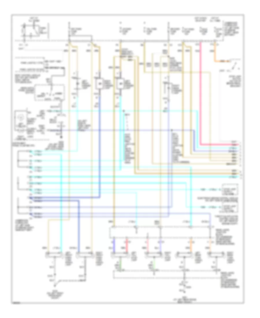
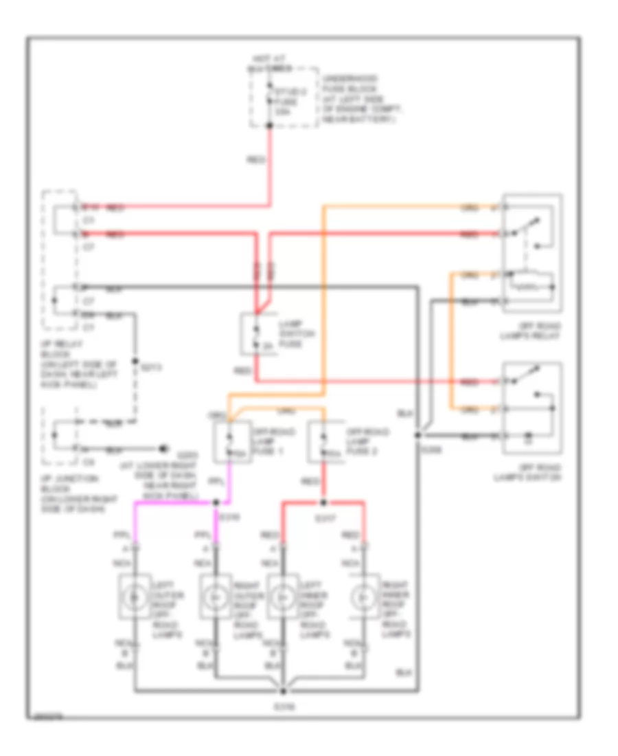
Off-Road Lighting Wiring Diagram, with Special Edition Package for Hummer H2 2007
 https://portal-diagnostov.com/license.html
Automotive Electricians Portal FZCO
Automotive Electricians Portal FZCO
https://portal-diagnostov.com/license.html
https://portal-diagnostov.com/license.html
Automotive Electricians Portal FZCO
Automotive Electricians Portal FZCOList of elements for Off-Road Lighting Wiring Diagram, with Special Edition Package for Hummer H2 2007:
- 15a
- E10
- G203 (at lower right side of dash, near right kick panel)
- Hot at all times
- I/p junction block (on lower right side of dash)
- I/p relay block (on left side of dash, near left kick panel)
- Lamp switch fuse
- Left inner roof off- road lamps
- Left outer roof off- road lamps
- Nca
- Off road lamps relay
- Off road lamps switch
- Off-road lamp fuse 1
- Off-road lamp fuse 2
- Red
- Right inner roof off- road lamps
- Right outer roof off- road lamps
- S208
- S213
- S316
- S317
- S318
- Stud 2 fuse 30a
- Underhood fuse block (at left side of engine compt, near battery)
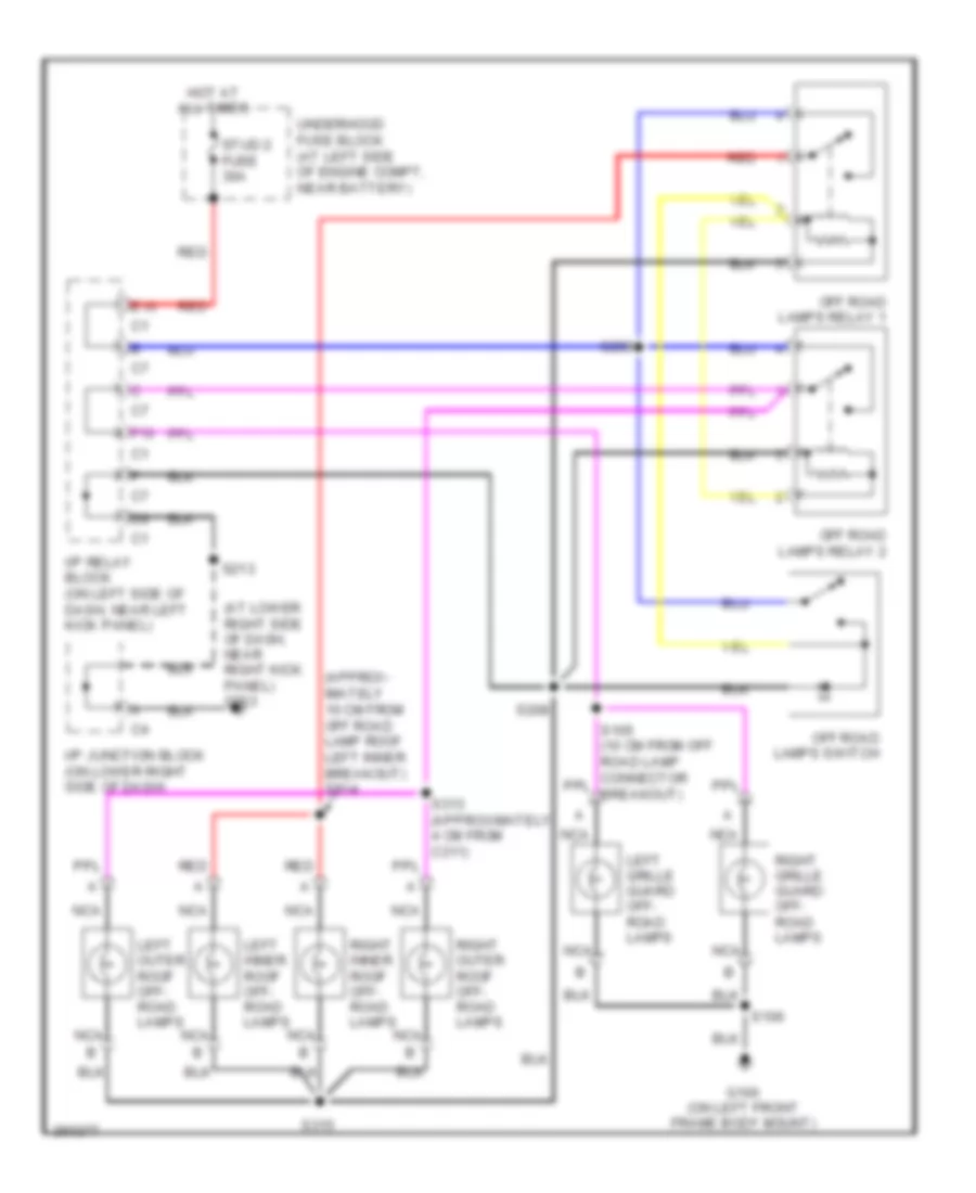
Off-Road Lighting Wiring Diagram, without Special Edition Package for Hummer H2 2007
 https://portal-diagnostov.com/license.html
Automotive Electricians Portal FZCO
Automotive Electricians Portal FZCO
https://portal-diagnostov.com/license.html
https://portal-diagnostov.com/license.html
Automotive Electricians Portal FZCO
Automotive Electricians Portal FZCOList of elements for Off-Road Lighting Wiring Diagram, without Special Edition Package for Hummer H2 2007:
- (approx- imately 10 cm from off road lamp roof left inner breakout) s314
- (at lower right side of dash, near right kick panel) g203
- E10
- F10
- G100 (on left front frame body mount)
- Hot at all times
- I/p junction block (on lower right side of dash)
- I/p relay block (on left side of dash, near left kick panel)
- Left grille guard off- road lamps
- Left inner roof off- road lamps
- Left outer roof off- road lamps
- Nca
- Off road lamps relay 1
- Off road lamps relay 2
- Off road lamps switch
- Red
- Right grille guard off- road lamps
- Right inner roof off- road lamps
- Right outer roof off- road lamps
- S106
- S208
- S209
- S213
- S313 (approximately 4 cm from c311)
- S315
- Stud 2 fuse 30a
- Underhood fuse block (at left side of engine compt, near battery)
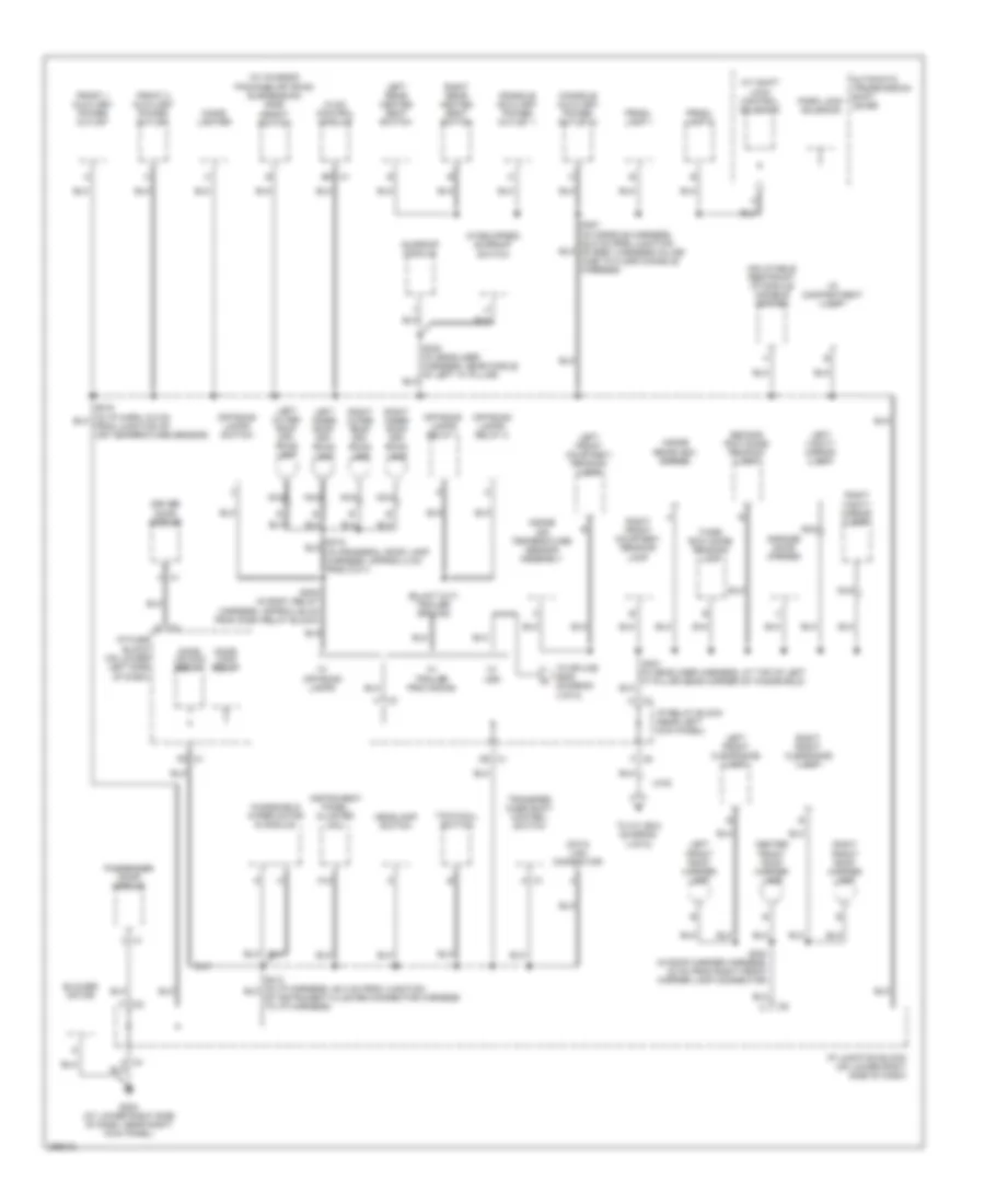
GROUND DISTRIBUTION
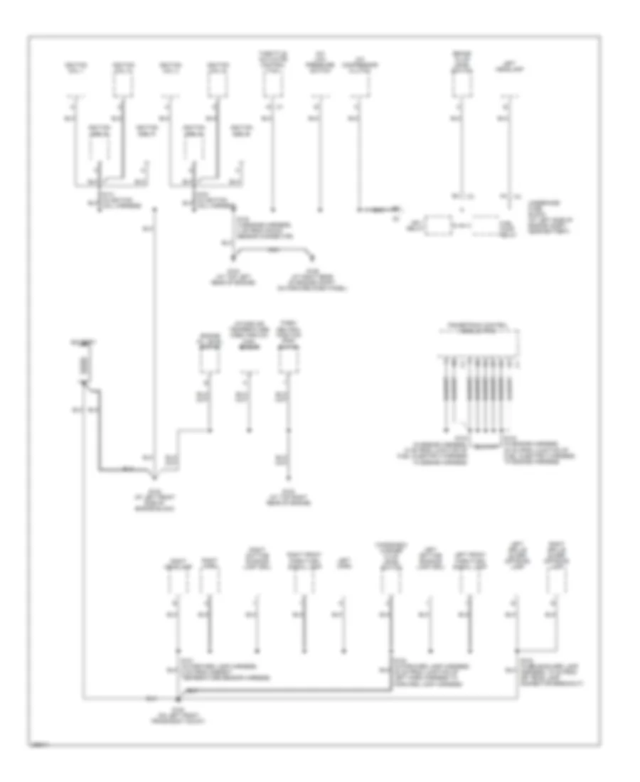
Ground Distribution Wiring Diagram (1 of 5) for Hummer H2 2007
 https://portal-diagnostov.com/license.html
Automotive Electricians Portal FZCO
Automotive Electricians Portal FZCO
https://portal-diagnostov.com/license.html
https://portal-diagnostov.com/license.html
Automotive Electricians Portal FZCO
Automotive Electricians Portal FZCOList of elements for Ground Distribution Wiring Diagram (1 of 5) for Hummer H2 2007:
- A/c compressor clutch
- A/c low pressure switch
- Battery
- Brake fluid level switch
- Engine oil level switch
- Forward lamp harness)
- Fuel pump relay
- G100 (on left front frame body mount)
- G102 (at left front side of engine block)
- G103 (at top right rear of engine)
- G104 (at top left rear of engine)
- G106 (at right rear of engine compt, on forward dash panel)
- Ign 1 relay
- Ignition coil 1
- Ignition coil 2
- Ignition coil 3
- Ignition coil 4
- Ignition coil 5
- Ignition coil 6
- Ignition coil 7
- Ignition coil 8
- Intake air temperature/ mass airflow (maf) sensor
- Left daytime running lamp (drl)
- Left front park/turn signal lamp
- Left grille guard off-road lamp
- Left headlamp
- Left horn
- Nca
- Park/ neutral position (pnp) switch
- Powertrain control module (pcm)
- Right daytime running lamp (drl)
- Right front park/turn signal lamp
- Right grille guard off-road lamp
- Right headlamp
- Right horn
- S102 (in engine harness, 4 cm from knock sensor connector)
- S103 (in engine harness, 10 cm from junction of fuel injector 3 harness to engine harness)
- S104 (in engine harness, 30 cm from junction of fuel injector 3 harness to engine harness)
- Throttle actuator control (tac)
- Underhood fuse block (at left side of engine compt, near battery)
- Windshield washer fluid level switch
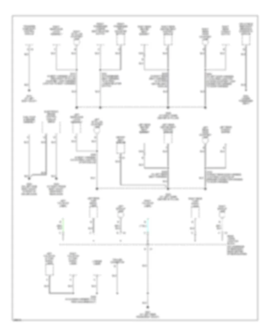
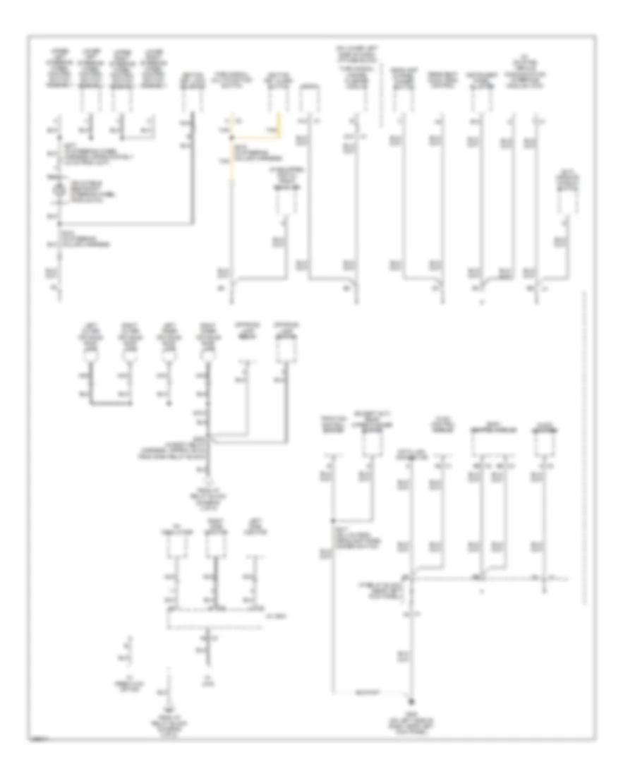
Ground Distribution Wiring Diagram (2 of 5) for Hummer H2 2007
 https://portal-diagnostov.com/license.html
Automotive Electricians Portal FZCO
Automotive Electricians Portal FZCO
https://portal-diagnostov.com/license.html
https://portal-diagnostov.com/license.html
Automotive Electricians Portal FZCO
Automotive Electricians Portal FZCOList of elements for Ground Distribution Wiring Diagram (2 of 5) for Hummer H2 2007:
- (on underside of rear body, near center of rear bumper)
- C3 a
- Electronic brake control module (ebcm)
- Front passenger lumbar/ seat bolster switch
- Front passenger seat adjuster switch
- Fuel pump & sender assembly
- G300 (on left side body mount, in front of driver door)
- G302 (at left inner center "b" pillar)
- G304 (under passenger seat)
- G306 (at right inner center "b" pillar)
- G310 (at left body mount)
- G401 (at left rear frame body mount)
- G403 (at right frame body mount, near right rear door)
- Inflatable restraint sensing & diagnostic module
- Left "b" pillar courtesy lamp
- Left backup lamp
- Left rear door courtesy lamp
- Left rear door latch assembly
- Left rear heated seat control module
- Left rear heated seat element
- Left rear turn signal lamp
- Left rear window switch
- Left tail/stop & turn signal lamp
- Left tail/stop lamp
- License lamp
- Memory seat module
- Nca
- Rear lamps junction block
- Right "b" pillar courtesy lamp
- Right backup lamp
- Right rear door courtesy lamp
- Right rear door latch assembly
- Right rear heated seat control module
- Right rear heated seat element
- Right rear turn signal lamp
- Right rear window switch
- Right tail/stop & turn signal lamp
- Right tail/stop lamp
- S306 (in left rear seat harness)
- S310 (in body harness, 8.5 cm from right "b" pillar courtesy lamp harness junction to body harness)
- S381 (in passenger seat harness, 16 cm from lumbar bolster switch)
- S390 (in body harness, 18.5 cm from junction of sir module)
- S393 (in right rear seat harness, 34 cm from heated seat module)
- S405 (in chassis harness 13 cm from g405 breakout)
- S720 (in right rear door harness, 12 cm from junction of speaker connector harness to door harness)
- S820 (in left door harness, 11.5 cm from junction of door courtesy lamp connector harness to door harness)
- Trailer connector
- Transfer case shift control module
Ground Distribution Wiring Diagram (3 of 5) for Hummer H2 2007
 https://portal-diagnostov.com/license.html
Automotive Electricians Portal FZCO
Automotive Electricians Portal FZCO
https://portal-diagnostov.com/license.html
https://portal-diagnostov.com/license.html
Automotive Electricians Portal FZCO
Automotive Electricians Portal FZCOList of elements for Ground Distribution Wiring Diagram (3 of 5) for Hummer H2 2007:
- (if equipped) sunroof switch
- (w/ chassis package off road suspension) ride height switch
- A/t shift lock control solenoid
- A12
- Automatic transmission shift lever
- Blower motor
- C1 a
- C1 b9
- C1 d9
- C1 f6
- C2 f
- C3 c
- C3 d
- C7 f
- C8 f
- Center front roof marker lamp
- Cigar lighter
- Console auxiliary power outlet 1
- Console auxiliary power outlet 2
- Data link connector
- Door lock relay
- Door unlock relay
- Driver door module
- Front 1 auxiliary power outlet
- Front 2 auxiliary power outlet
- G203 (at lower right side of dash, near right kick panel)
- Garage door opener
- Headlamp switch
- Hvac control module
- I/p compartment lamp
- I/p fuse block (on lower left side of dash)
- I/p junction block (on lower right side of dash)
- I/p relay block (near left kick panel)
- Inflatable restraint i/p module disable switch
- Inside air temperature sensor assembly
- Inside rearview mirror
- Instrument panel cluster (ipc)
- Left front clearance lamp
- Left front courtesy/ reading lamp
- Left front roof marker lamp
- Left inner roof off- road lamp
- Left outer roof off- road lamp
- Left rear heated seat switch
- Left vanity mirror lamp
- Nca
- Off-road lamps relay 1
- Off-road lamps relay 2
- Off-road lamps switch
- Park lock solenoid
- Passenger door module
- Prndl lamp 1
- Prndl lamp 2
- Right front clearance lamp
- Right front courtesy/ reading lamp
- Right front roof marker lamp
- Right inner roof off- road lamp
- Right outer roof off- road lamp
- Right rear heated seat switch
- Right vanity mirror lamp
- S208 (in body relay harness, approx 25 cm from dash relay block)
- S303 (in roof marker harness, 22 cm from right front marker lamp connector)
- S351 (in console harness, 28.5 cm from junction of body harness in-line c355 to floor console harness)
- Second row dome/ reading lamp
- Sunroof module
- Third row dome/ reading lamp
- To a/v box (diagram 4 of 5)
- To splice s208 (diagram 4 of 5)
- Tow/haul switch
- Transfer case shift control switch
- Uwg
- W/ off-road lamps
- W/ trailer provisions
- W/ usd
- Windshield wiper motor & module
Ground Distribution Wiring Diagram (4 of 5) for Hummer H2 2007
 https://portal-diagnostov.com/license.html
Automotive Electricians Portal FZCO
Automotive Electricians Portal FZCO
https://portal-diagnostov.com/license.html
https://portal-diagnostov.com/license.html
Automotive Electricians Portal FZCO
Automotive Electricians Portal FZCOList of elements for Ground Distribution Wiring Diagram (4 of 5) for Hummer H2 2007:
- (25.4 cm from headlamp panel dimmer switch)
- (except sut) rear wiper/washer switch
- (if equipped) digital radio receiver
- (on lower left side of dash) i/p fuse block
- (sut) midgate window switch
- (w/ on star) vehicle communication interface module (vcim)
- A/v box
- A12
- Audio amplifier
- B12
- Body control module
- C1 a8
- C1 f8
- C2 a
- C2 b6
- C3 b6
- D10
- Data link connector
- Fm modulator
- From i/p relay block (diagram 3 of 5)
- G200 (on left side of dash, near left kick panel)
- Headlamp & panel dimmer switch
- Hvac control module
- I/p relay block (near left kick panel)
- Ignition key alarm switch
- Ignition key lock solenoid
- Inflatable restraint steering wheel module coil
- Instrument panel cluster
- Left inner off road roof lamp
- Left outer off road roof lamp
- Left side monitor
- Lower left steering wheel control switch assembly
- Lower right steering wheel control switch assembly
- Nca
- Off-road lamp relay
- Off-road lamp switch
- Radio
- Rear seat audio (rsa) control
- Right inner off road roof lamp
- Right outer off road roof lamp
- Right side monitor
- S208 (in body relay harness, approx 25 cm from dash relay block)
- S217
- S218 (in steering column harness)
- S219 (in steering column harness) tan
- S277 (in steering wheel harness approximately 2.5 cm from c277)
- S318
- Tan
- Traction control switch
- Turn signal/ hazard flasher module
- Turn signal/ multifunction switch
- Upper left steering wheel control switch assembly
- Upper right steering wheel control switch assembly
- W/ free flow option
- W/ uwg
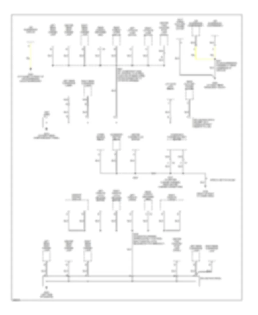
Ground Distribution Wiring Diagram (5 of 5) for Hummer H2 2007
 https://portal-diagnostov.com/license.html
Automotive Electricians Portal FZCO
Automotive Electricians Portal FZCO
https://portal-diagnostov.com/license.html
https://portal-diagnostov.com/license.html
Automotive Electricians Portal FZCO
Automotive Electricians Portal FZCOList of elements for Ground Distribution Wiring Diagram (5 of 5) for Hummer H2 2007:
- (not used)
- (sut) cargo auxiliary power outlet
- A c2
- Accessory ignition relay
- Air suspension compressor 1
- Air suspension compressor 2
- Air suspension module
- Center high mounted stop lamp (chmsl)
- Center rear roof marker lamp
- G105 (front of right cylinder head)
- G320 (left side of midgate)
- G402 (attached to front of air suspension mounting bracket)
- G405 (at right rear frame body mount)
- G410 (on right rear inner side body panel)
- Heated washer fluid switch
- Left liftgate ajar switch
- Left midgate latch
- Left midgate latch release switch
- Left rear clearance lamp
- Left rear roof marker lamp
- Lift gate lock relay
- Midgate control module
- Nca
- Rear auxiliary power outlet
- Rear window defogger grid
- Rear window wiper module
- Right liftgate ajar switch
- Right midgate latch
- Right midgate latch release switch
- Right rear clearance lamp
- Right rear roof marker lamp
- S107 (in heater washer harness, near heated washer connectors)
- S203
- S339 (in midgate harness approximately 5 cm from right midgate latch release switch breakout)
- S407 (in air suspension harness at rear underside of vehicle)
- S901 (at lower right side of liftgate, 10 cm from junction of rear wiper motor connector to liftgate harness)
- Special edition sales
- Splice pack sp320
- Splice pack sp410 (except sut) (middle of right rear "d" pillar)
- Windshield washer solvent heater
- Wiper enable relay
HEADLIGHTS
Headlights Wiring Diagram for Hummer H2 2007
 https://portal-diagnostov.com/license.html
Automotive Electricians Portal FZCO
Automotive Electricians Portal FZCO
https://portal-diagnostov.com/license.html
https://portal-diagnostov.com/license.html
Automotive Electricians Portal FZCO
Automotive Electricians Portal FZCOList of elements for Headlights Wiring Diagram for Hummer H2 2007:
- A12
- Amb lt low ref
- Amb lt sens sig
- Ambient light sensor (on top center of dash)
- Auto
- B12
- Body control module (on top left side of dash, above i/p fuse block)
- Drl defeat
- Drl fuse 10a
- Drl relay
- Drl rly ctrl
- Drl sw sig
- Flash to pass
- G100 (on left front frame body mount)
- G104 (at top left rear of engine)
- G200 (on left side of dash, near left kick panel)
- Ground
- Hdlp dim sw sig
- Hdlp high relay
- Hdlp low relay
- Head
- Headlamp & panel dimmer switch
- Hi bm rly ctrl
- Hi hdlp lt fuse 10a
- Hi hdlp rt fuse 10a
- Hi/lo beam select
- High beam ind
- Hlps on sig
- Hot at all times
- Hot in on or start
- I/p relay block (on left side of dash, near left kick panel)
- Ign
- Ign e fuse 10a
- Instrument panel cluster (ipc)
- Left daytime running lamp
- Left headlamp
- Lo bm rly ctrl
- Lo hdlp lt fuse 10a
- Lo hdlp rt fuse 10a
- Logic
- Park
- Park brake switch
- Park lamp sw on
- Pnk
- Prk brk
- Right daytime running lamp
- Right headlamp
- S100
- S101
- S102
- S219
- Serial data
- Splice pack sp205 (in i/p harness, on left side of dash, near footwell courtesy lamp)
- Tan
- Turn signal multi-function switch
- Underhood fuse block (at left side of engine compt, near battery)
HORN
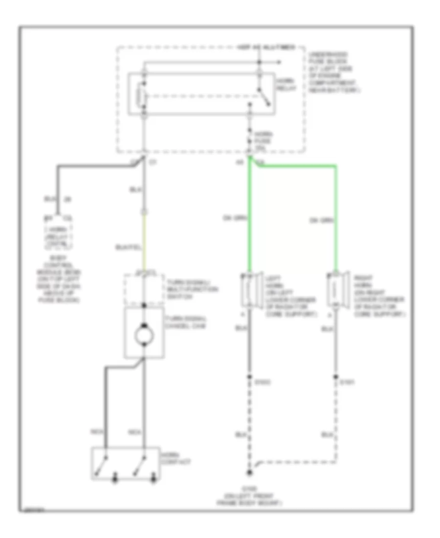
Horn Wiring Diagram for Hummer H2 2007
 https://portal-diagnostov.com/license.html
Automotive Electricians Portal FZCO
Automotive Electricians Portal FZCO
https://portal-diagnostov.com/license.html
https://portal-diagnostov.com/license.html
Automotive Electricians Portal FZCO
Automotive Electricians Portal FZCOList of elements for Horn Wiring Diagram for Hummer H2 2007:
- Body control module (bcm) (on top left side of dash, above i/p fuse block)
- G c1
- G100 (on left front frame body mount)
- Horn contact
- Horn fuse 15a
- Horn relay
- Horn relay cntrl
- Hot at all times
- Left horn (on left lower corner of radiator core support)
- Nca
- Right horn (on right lower corner of radiator core support)
- S101
- S10o
- Turn signal cancel cam
- Turn signal/ multi-function switch
- Underhood fuse block (at left side of engine compartment, near battery)
INSTRUMENT CLUSTER
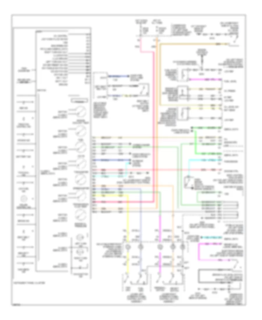
Instrument Cluster Wiring Diagram for Hummer H2 2007
 https://portal-diagnostov.com/license.html
Automotive Electricians Portal FZCO
Automotive Electricians Portal FZCO
https://portal-diagnostov.com/license.html
https://portal-diagnostov.com/license.html
Automotive Electricians Portal FZCO
Automotive Electricians Portal FZCOList of elements for Instrument Cluster Wiring Diagram for Hummer H2 2007:
- (at top right rear of engine) g103
- (center of dash) radio
- (in chassis harness, 21.5 cm from g300)
- (on left front of engine compt) powertrain control module (pcm)
- (on lower right side of oil pan) engine oil level switch
- 5v ref
- A10
- A11
- A12
- Abs ind
- Air bag ind
- B10
- B11
- B12
- B26
- Batt volt
- Battery ind
- Body control module (bcm) (on top left side of dash, above i/p fuse block)
- Brake fluid level sens sig
- Brake fluid level switch (on left side of brake fluid reservoir)
- Brake ind
- C206 b13
- C277
- Class 2 serial data
- Computer data lines system
- Cruise control ind
- Data
- Dic fuel sig
- Dic set/reset sw sig
- Dic switch sig
- Dic toggle switch sig
- Dimming ctrl
- Driver info center
- Ect sens
- Electronic brake control module (ebcm) (on left side of inner frame)
- Eng speed sig
- Engine controls system
- Engine coolant temp
- Engine coolant temperature (ect) sensor (near rear of engine block, below exhaust manifold)
- Engine oil pressure
- Engine oil pressure (eop) sensor (at left rear of engine)
- Engine spd
- Exterior lights system
- F7 c1
- Fuel
- Fuel info
- Fuel level
- Fuel pump & sender assembly (in fuel tank)
- G104 (at top left rear of engine)
- G200 (on left side of dash, near left kick panel)
- G203 (at lower right side of dash, near right kick panel)
- Ground
- High beam ind
- Hot at all times
- Hot in run or start
- I/p relay block (on left side of dash, near left kick panel)
- Ign 1 volt
- Ign e fuse 10a
- Ignition
- Illum ground
- Illumination
- Inflatable restraint sensing & diagnostic module (sdm) (under left front seat)
- Inflatable restraint steering wheel module coil (on steeringl column, behind steering wheel)
- Instrument panel cluster
- Ipc class 2/serial data
- Ipc/dic fuse 10a
- Left seat belt sw
- Left turn ind
- Left turn sig volt
- Logic
- Low fuel ind
- Low ref
- Low wash fluid ind sig
- Lower left steering wheel control switch assembly
- Lower right steering wheel control switch assembly
- Malfunction ind
- Mil
- Mil control
- Nca
- Oil level sw
- Oil press
- Park brake
- Park brake switch (part of parking brake assembly)
- Personal- ization
- Pnk
- Prnd321
- Red
- Right turn ind
- Right turn sig volt
- S102
- S103
- S213
- S218
- S277
- S304
- Seat belt ind
- Seat belt switch (at right side) of driver seat)
- Security ind
- Select switch
- Serial data
- Speedometer
- Tachometer
- Tow/haul ind
- Traction control ind
- Transmission fluid temp
- Trip info
- Trip/ odometer
- Underhood fuse block (at left side of engine compt, near battery)
- Volts
- Vss
- Wiper/washer system
INTERIOR LIGHTS
Courtesy Lamps Wiring Diagram (1 of 3) for Hummer H2 2007
 https://portal-diagnostov.com/license.html
Automotive Electricians Portal FZCO
Automotive Electricians Portal FZCO
https://portal-diagnostov.com/license.html
https://portal-diagnostov.com/license.html
Automotive Electricians Portal FZCO
Automotive Electricians Portal FZCOList of elements for Courtesy Lamps Wiring Diagram (1 of 3) for Hummer H2 2007:
- (on left side of dash, near left kick panel) g200
- (on left side of dash, near left kick panel) i/p relay block
- A11
- Ajar
- Ajar input
- B12
- Batt pos volt
- Body control module (bcm) (on top left side of dash, above i/p fuse block)
- Class 2 data
- Class 2 serial data
- Ctsy lamp ctrl
- Ctsy lamp on sig
- Ctsy lamp on sw
- Ctsy lamp power
- Door ajar sig
- Driver door latch assembly (at rear of driver door)
- Driver door module (ddm) (behind driver's door panel)
- Except sut
- G302 (at left inner center "b" pillar)
- G306 (at right inner center "b" pillar)
- G320 (left side of midgate)
- G410
- Gnd
- Headlamp & panel dimmer switch
- Hot at all times
- I/p fuse block (on lower left side of dash)
- Int lamp defeat sw
- Int lamp defeat sw sig
- Left front door courtesy lamp
- Left liftgate ajar switch (at lower left side of liftgate)
- Left midgate latch (left side of midgate, at latch assembly)
- Left rear door courtesy lamp
- Left rear door latch assembly (at rear of door)
- Lift gate ajar sw sig
- Low ref
- Lr door ajar sw sig
- Midgate ajar sig
- Midgate control module (mcm) (center of midgate assembly, attached to window regulator assembly)
- Right liftgate ajar switch (at lower right side of liftgate)
- Right midgate latch (left side of midgate, at latch assembly)
- Right rear door courtesy lamp
- Right rear door latch assembly (at rear of door)
- Rr door ajar sw sig
- S310
- S339
- S390
- S720
- S820
- S901
- Sp205 (on left side of dash, near footwell courtesy lamp)
- Splice pack sp320
- Splice pack sp410 (inside right rear cargo area, at middle of right rear "d" pillar)
- Sut
- Tan
- Tbc 2b fuse 15a
Courtesy Lamps Wiring Diagram (2 of 3) for Hummer H2 2007
 https://portal-diagnostov.com/license.html
Automotive Electricians Portal FZCO
Automotive Electricians Portal FZCO
https://portal-diagnostov.com/license.html
https://portal-diagnostov.com/license.html
Automotive Electricians Portal FZCO
Automotive Electricians Portal FZCOList of elements for Courtesy Lamps Wiring Diagram (2 of 3) for Hummer H2 2007:
- 2nd row courtesy/ reading lamps
- 3rd row courtesy/ reading lamps (except sut)
- Dome
- Ground distribution system
- Left front courtesy/ reading lamp
- Left vanity mirror lamp
- Nca
- Reading
- Right front courtesy/ reading lamp
- Right vanity mirror lamp
- S300 (in headliner harness, 10 cm from junction of courtesy/reading lamp center harness to headliner harness)
- S301
- S305 (in headliner harness, 5 cm from top mounting clip)
- Tan
Courtesy Lamps Wiring Diagram (3 of 3) for Hummer H2 2007
 https://portal-diagnostov.com/license.html
Automotive Electricians Portal FZCO
Automotive Electricians Portal FZCO
https://portal-diagnostov.com/license.html
https://portal-diagnostov.com/license.html
Automotive Electricians Portal FZCO
Automotive Electricians Portal FZCOList of elements for Courtesy Lamps Wiring Diagram (3 of 3) for Hummer H2 2007:
- A12
- Ajar
- C10
- Class 2 srl data
- Ctsy lamp control
- Ctsy lamp power
- Door ajar sw sig
- G200 (on left side of dash, near left kick panel)
- G203 (at lower right side of dash, near right kick panel)
- G302 (at left inner center "b" pillar)
- G306 (at right inner center "b" pillar)
- I/p compartment lamp/switch
- I/p fuse block (on lower left side of dash)
- I/p junction block (on lower right side of dash)
- I/p relay block (on left side of dash, near left kick panel)
- Left "b" pillar courtesy lamp
- Low ref
- Passenger door latch assembly (at rear of passenger door)
- Passenger door module (pdm) (in passenger door)
- Right "b" pillar courtesy lamp
- Right front door courtesy lamp
- S213
- S215
- S310
- S390
- Tan
Instrument Illumination Wiring Diagram (1 of 3) for Hummer H2 2007
 https://portal-diagnostov.com/license.html
Automotive Electricians Portal FZCO
Automotive Electricians Portal FZCO
https://portal-diagnostov.com/license.html
https://portal-diagnostov.com/license.html
Automotive Electricians Portal FZCO
Automotive Electricians Portal FZCOList of elements for Instrument Illumination Wiring Diagram (1 of 3) for Hummer H2 2007:
- (on top left side of dash, above i/p fuse block) body control module (bcm)
- 4 hi ind
- 4 hi ind control
- 4 hi locked ind
- 4 hi locked ind control
- 4 lo ind
- 4 lo ind control
- 5 volt ref
- Auto
- B+ class 2 srl data
- B11
- Back only ind
- C1 c5
- C1 f6
- C1 f8
- C3 d
- Computer data lines system
- Ddm fuse 15a
- Dimmer ptnomtr low ref
- Dimmer ptnomtr sig
- Driver door module (ddm) (behind driver's door panel)
- Drl defeat
- Drl off ind
- Drl off ind sw
- G200 (on left side of dash, near left kick panel)
- G203 (at lower right side of dash, near right kick panel)
- Gnd
- Head
- Headlamp & panel dimmer switch
- Headlamp on ind
- Headlamp on ind ctrl
- High heat ind
- Hot at all times
- I/p fuse block (on lower left side of dash)
- I/p junction block (on lower right side of dash)
- I/p lamps dimming ctrl
- I/p relay block (on left side of dash, near left kick panel)
- Ign vol
- Illu ctrl
- Illum
- Illum ctrl
- Illum lamps dimming ctrl
- Ind ctrl
- Logic
- Low heat ind
- Med heat ind
- Memory/heated seat switch
- Park
- Passenger door module (pdm) (in passenger door)
- Passenger heated seat switch
- Pdm fuse 15a
- Pnk
- Rear diff lock ind ctrl
- Rear differential lock ind
- Red
- S213
- Sply vol
- Sw illum ctrl
- Sw on sig
- Transfer case shift control module (behind headlight switch)
- Transfer case shift control switch
- Window lockout ind
- Window lockout ind ctrl
- Window/ door lock sw illum
Instrument Illumination Wiring Diagram (2 of 3) for Hummer H2 2007
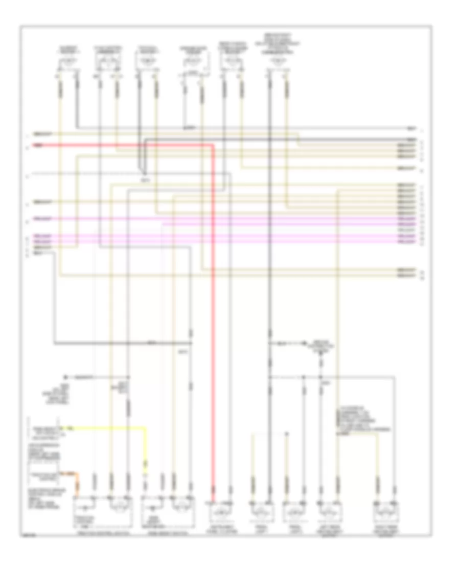 https://portal-diagnostov.com/license.html
Automotive Electricians Portal FZCO
Automotive Electricians Portal FZCO
https://portal-diagnostov.com/license.html
https://portal-diagnostov.com/license.html
Automotive Electricians Portal FZCO
Automotive Electricians Portal FZCOList of elements for Instrument Illumination Wiring Diagram (2 of 3) for Hummer H2 2007:
- (behind right side of dash) inflatable restraint i/p module disable switch
- (in console harness, 7 cm from junction of body harness in-line c355 to floor console harness) s350
- A11
- A12
- A7 c1
- Air suspension module (near left side of compressor)
- Electronic brake control module (ebcm) (on left side of inner frame)
- G ride height active sw c2
- G200 (on left side of dash, near left kick panel)
- Garage door opener
- Ground distribution system
- Hvac control assembly
- Ind control
- Instrument panel cluster
- Left rear heated seat switch
- Logic
- Prndl lamp 1
- Prndl lamp 2
- Rear window wiper/washer switch
- Red
- Ride height active ind
- Ride height switch
- Right rear heated seat switch
- S213
- S215
- S217 (except sut)
- S301
- S351
- Sunroof switch
- Tow/haul switch
- Traction control ind
- Traction control switch
- Traction ind control
Instrument Illumination Wiring Diagram (3 of 3) for Hummer H2 2007
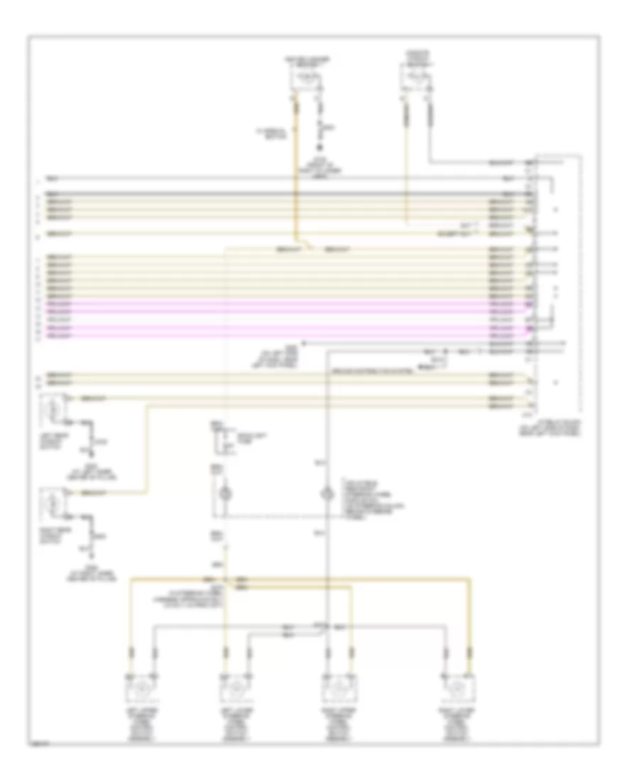 https://portal-diagnostov.com/license.html
Automotive Electricians Portal FZCO
Automotive Electricians Portal FZCO
https://portal-diagnostov.com/license.html
https://portal-diagnostov.com/license.html
Automotive Electricians Portal FZCO
Automotive Electricians Portal FZCOList of elements for Instrument Illumination Wiring Diagram (3 of 3) for Hummer H2 2007:
- A11
- Backlight fuse
- C10
- Except sut
- G105 (front of right cylinder head)
- G200 (on left side of dash, near left kick panel)
- G302 (at left inner center "b" pillar)
- G306 (at right inner center "b" pillar)
- Ground distribution system
- Heated washer switch
- I/p relay block (on left side of dash, near left kick panel)
- Inflatable restraint steering wheel module coil (on steering column, behind steering wheel)
- Left lower steering wheel control switch assembly
- Left rear window switch
- Left upper steering wheel control switch assembly
- Midgate window switch
- Right lower steering wheel control switch assembly
- Right rear window switch
- Right upper steering wheel control switch assembly
- S218
- S277
- S278 (in steering wheel harness approximately 2.5 cm (1 in) from c277)
- S720
- S820
- Sut
- W/ special edition
MEMORY SYSTEMS
Driver"s Memory Seat Wiring Diagram (1 of 2) for Hummer H2 2007
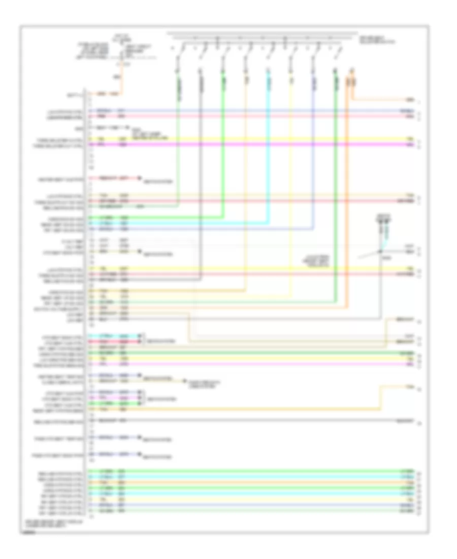 https://portal-diagnostov.com/license.html
Automotive Electricians Portal FZCO
Automotive Electricians Portal FZCO
https://portal-diagnostov.com/license.html
https://portal-diagnostov.com/license.html
Automotive Electricians Portal FZCO
Automotive Electricians Portal FZCOList of elements for Driver"s Memory Seat Wiring Diagram (1 of 2) for Hummer H2 2007:
- (4.5 cm from memory seat module c3)
- 5 volt ref
- 570a
- 570b
- Batt (+)
- C10 h
- Class 2 serial data
- Computer data lines system
- Driver memory seat module (under driver seat)
- Driver seat adjuster switch
- Frt vert dn sw sig
- Frt vert mtr dn ctrl
- Frt vert mtr pos sen
- Frt vert mtr up ctrl
- Frt vert up sw sig
- G302 (at left inner center "b" pillar)
- Gnd
- Heated seat cus pwr
- Heated seat temp sig
- Horiz fwd sw sig
- Horiz mtr fwd ctrl
- Horiz mtr pos sen sig
- Horiz mtr rwd ctrl
- Horiz rwd sw sig
- Hot at all times
- Htd seat back ctrl
- Htd seat back pwr
- Htd seat cus ctrl
- Htd seat cus pwr
- I/p relay block (on left side of dash, near left kick panel)
- Low ref
- Lum horiz pos sen sig
- Lum mtr fwd ctrl
- Lum mtr rwd ctrl
- Lum mtr rwd ctrl lum mtr rwd ctrl
- Pass htd seat back pwr
- Pass htd seat temp sig
- Pnk
- Pnk pnk
- Rear vert dn sw sig
- Rear vert mtr pos sens
- Rear vert up sw sig
- Recline fwd sw sig
- Recline mtr fwd ctrl
- Recline mtr pos sen sig
- Recline mtr rwd ctrl
- Recline rwd sw sig
- Rr vert mtr dn ctrl
- Rr vert mtr up ctrl
- S328
- Seat circuit breaker 30a
- Seats system
- Tan
- Torso blstr in sw sig
- Torso blstr out sw sig
- Torso bolster in ctrl
- Torso bolster out ctrl
- Trso blstr pos sens sig
- Volt ref
Driver"s Memory Seat Wiring Diagram (2 of 2) for Hummer H2 2007
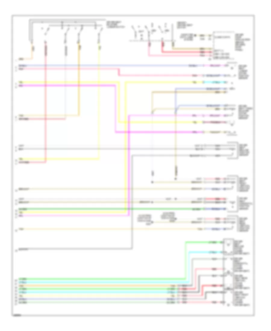 https://portal-diagnostov.com/license.html
Automotive Electricians Portal FZCO
Automotive Electricians Portal FZCO
https://portal-diagnostov.com/license.html
https://portal-diagnostov.com/license.html
Automotive Electricians Portal FZCO
Automotive Electricians Portal FZCOList of elements for Driver"s Memory Seat Wiring Diagram (2 of 2) for Hummer H2 2007:
- (10 cm from junction of c330 & c328)
- (5 cm from junction of c330 & c328) s326
- Batt (+)
- Class 2 data
- Computer data lines system
- Driver door module (ddm) (behind driver's door panel)
- Driver seat bolster/ lumbar switch
- Driver seat front vertical motor (under driver seat)
- Driver seat front vertical position sensor
- Driver seat horizontal motor (under driver seat)
- Driver seat horizontal position sensor
- Driver seat lumbar motor/ position sensor
- Driver seat rear vertical motor (under driver seat)
- Driver seat rear vertical position sensor
- Driver seat recline motor (under driver seat)
- Driver seat recline position sensor
- Driver seat torso bolster motor/ position sensor
- Exit
- Mem
- Mem 1 sw sig
- Mem 2 sw sig
- Memory/ heated seat switch
- Nca
- Pnk
- Red
- S327
- Tan
Memory Mirrors Wiring Diagram for Hummer H2 2007
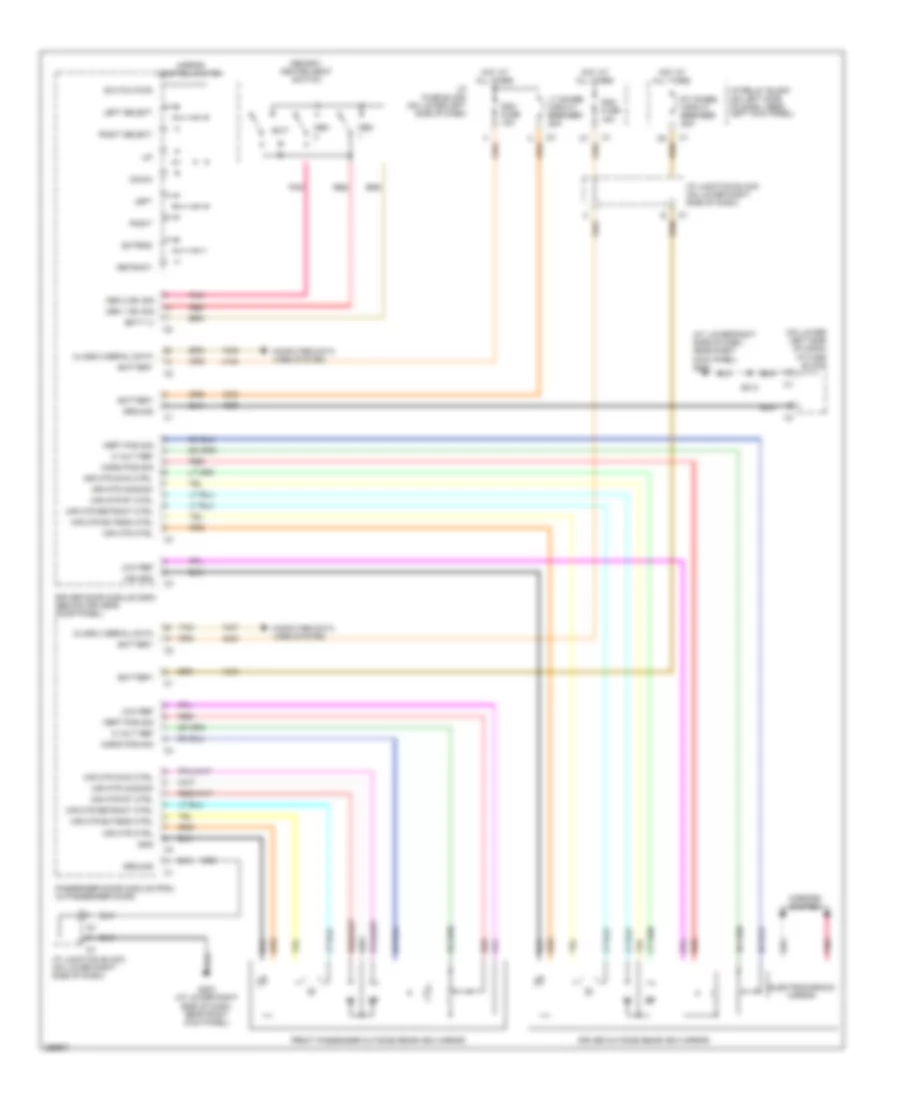 https://portal-diagnostov.com/license.html
Automotive Electricians Portal FZCO
Automotive Electricians Portal FZCO
https://portal-diagnostov.com/license.html
https://portal-diagnostov.com/license.html
Automotive Electricians Portal FZCO
Automotive Electricians Portal FZCOList of elements for Memory Mirrors Wiring Diagram for Hummer H2 2007:
- (at lower right side of dash, near right kick panel) g203
- (on lower left side of dash) i/p fuse block
- 5 volt ref
- Batt (+)
- Battery
- Class 2 serial data
- Computer data lines system
- Ddm fuse 15a
- Down
- Driver door module (ddm) (behind driver's door panel)
- Driver outside rearview mirror
- Electrochromic mirror
- Exit
- Extend
- Front passenger outside rearview mirror
- G203 (at lower right side of dash, near right kick panel)
- Gnd
- Ground
- Horiz pos sig
- Hot at all times
- I/p fuse block (on lower left side of dash)
- I/p junction block (on lower right side of dash)
- I/p relay block (on left side of dash, near left kick panel)
- Left
- Left select
- Low ref
- Lt doors circuit breaker 25a
- Mem
- Mem 1 sw sig
- Mem 2 sw sig
- Memory/ heated seat switch
- Mir gnd
- Mir htr ctrl
- Mir mtr common
- Mir mtr dwn ctrl
- Mir mtr extend ctrl
- Mir mtr retract ctrl
- Mir mtr rt ctrl
- Mirror control switch
- Mirrors system
- Passenger door module (pdm) (in passenger door)
- Pdm fuse 15a
- Pnk
- Red
- Retract
- Right
- Right select
- Rt doors circuit breaker 25a
- S213
- Switch pwr
- Tan
- Vert pos sig
NAVIGATION
Navigation Wiring Diagram for Hummer H2 2007
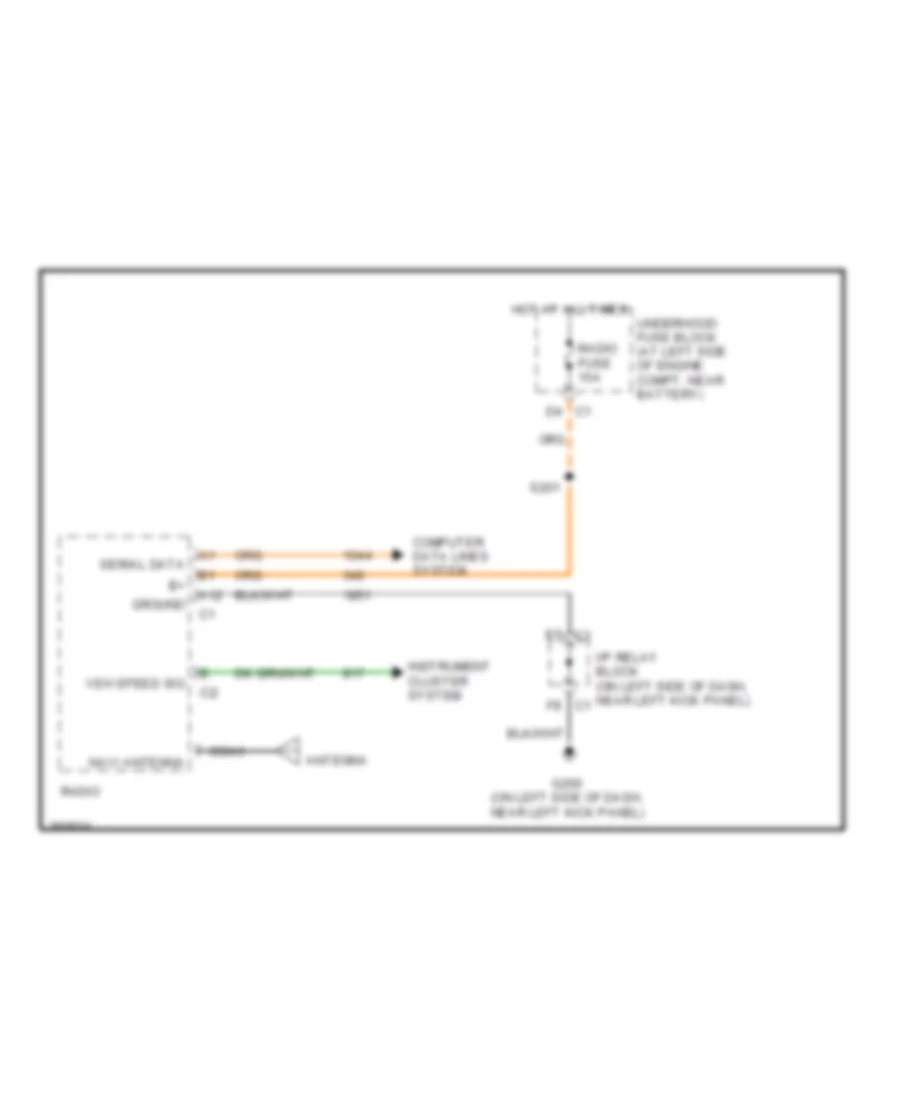 https://portal-diagnostov.com/license.html
Automotive Electricians Portal FZCO
Automotive Electricians Portal FZCO
https://portal-diagnostov.com/license.html
https://portal-diagnostov.com/license.html
Automotive Electricians Portal FZCO
Automotive Electricians Portal FZCOList of elements for Navigation Wiring Diagram for Hummer H2 2007:
- A12
- Antenna
- Coax
- Computer data lines system
- G200 (on left side of dash, near left kick panel)
- Ground
- Hot at all times
- I/p relay block (on left side of dash, near left kick panel) c1
- Instrument cluster system
- Navi antenna
- Radio
- Radio fuse 15a
- S201
- Serial data
- Underhood fuse block (at left side of engine compt, near battery)
- Veh speed sig
POWER DISTRIBUTION
Power Distribution Wiring Diagram (1 of 6) for Hummer H2 2007
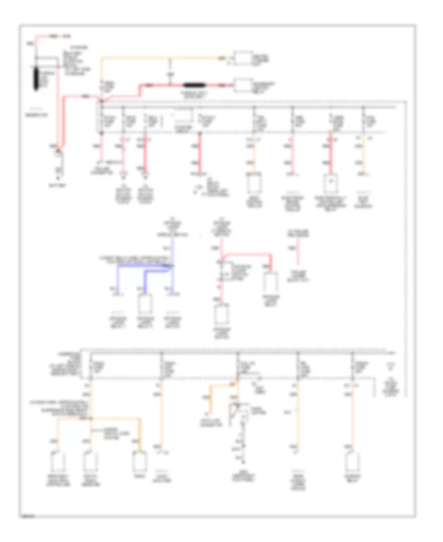 https://portal-diagnostov.com/license.html
Automotive Electricians Portal FZCO
Automotive Electricians Portal FZCO
https://portal-diagnostov.com/license.html
https://portal-diagnostov.com/license.html
Automotive Electricians Portal FZCO
Automotive Electricians Portal FZCOList of elements for Power Distribution Wiring Diagram (1 of 6) for Hummer H2 2007:
- (in body relay harn, approximately 8 cm from off road lamp relay 1) s209
- (in dash harn, approximately 24 cm from air suspension ride height switch breakout) s201
- (not used)
- 4ws fuse 15a
- A c7
- A12
- Abs fuse 60a
- Accessory ignition relay
- Audio amplifier
- B c9
- B11 c1
- B12 c1
- Battery
- Battery cable junction block (at left side of engine)
- Body control module
- Cig ltr fuse 15a
- Cigar lighter
- D12 c1
- Data link connector
- Digital radio receiver
- E10
- Electronic brake control module
- Electronically controlled air suspension relay
- Evap vent solenoid
- G203 (near right kick panel)
- Generator
- Heated washer unit
- I/p relay block (near left kick panel)
- Ign a fuse 40a
- Ign b fuse 40a
- Mega fuse 60a
- Off-road lamps relay
- Off-road lamps relay 1
- Off-road lamps relay 2
- Off-road lamps switch
- Off-road lamps switch fuse
- Radio
- Radio amp fuse 30a
- Radio fuse 15a
- Rear seat audio (rsa) controller
- Rear window wiper module
- Red
- Rr wpr fuse 25a
- S band digital audio system
- S/roof fuse 25a
- S215
- Starter
- Starter relay
- Stud 1 fuse 40a
- Stud 2 fuse 30a
- Sunroof relay
- Suv
- Tbc batt fuse 10a
- To ignition switch (diagram 5 of 6)
- To ignition switch (diagram 6 of 6)
- To ipc/dic fuse (diagram 2 of 6)
- Trailer connector
- Underhood fuse block (at left side of engine compt, near battery)
- Vses/ ecas fuse 60a
- W/ off-road lamps w/ special edition
- W/ off-road lamps w/o special edition
- W/ trailer provisions
- Ws2
Power Distribution Wiring Diagram (2 of 6) for Hummer H2 2007
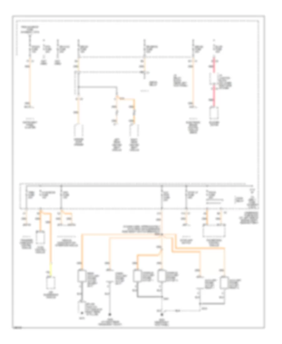 https://portal-diagnostov.com/license.html
Automotive Electricians Portal FZCO
Automotive Electricians Portal FZCO
https://portal-diagnostov.com/license.html
https://portal-diagnostov.com/license.html
Automotive Electricians Portal FZCO
Automotive Electricians Portal FZCOList of elements for Power Distribution Wiring Diagram (2 of 6) for Hummer H2 2007:
- (in dash harn, approximately 30 cm from air suspension ride height switch breakout) s200
- (not used)
- Air suspension module
- Aux pwr fuse 20a
- Auxiliary power outlet- front 1
- Auxiliary power outlet- front 2
- B c3
- B c5
- B11
- Blower motor
- Blwr fuse 40a
- C1 f12
- C10
- Cargo auxiliary power outlet (sut)
- Console auxiliary power outlet 1
- Console auxiliary power outlet 2
- D c4
- Defog relay
- E11 c1
- Electronic brake control module (ebcm)
- F/pmp relay
- F7 c1
- From sunroof fuse (diagram 1 of 6)
- G203 (near right kick panel)
- G405 (at right rear frame body mount)
- G410
- Garage door opener
- Hvac control module
- Hvac/ecas fuse 10a
- I/p junction block (on lower right side of dash)
- I/p relay block (near left kick panel)
- Info fuse 15a
- Instrument panel cluster
- Ipc/dic fuse 10a
- Left rear heated seat module
- Pcm b fuse 20a
- Powertrain control module
- Rear auxiliary power outlet (except sut)
- Red
- Right rear heated seat module
- Rr defog fuse 30a
- Rr hvac fuse 30a
- Rtd fuse 30a
- S215
- S351
- Seo b1 fuse 15a
- Seo b2 fuse 30a
- Splice pack 410 (at middle of right rear "d" pillar)
- Stop lp fuse 25a
- Stoplamp switch
- To lbec 1 fuse (diagram 3 of 6)
- Transfer case shift control module
- Trec fuse 30a
- Underhood fuse block (at left side of engine compt, near battery)
- Vehicle communication interface module
Power Distribution Wiring Diagram (3 of 6) for Hummer H2 2007
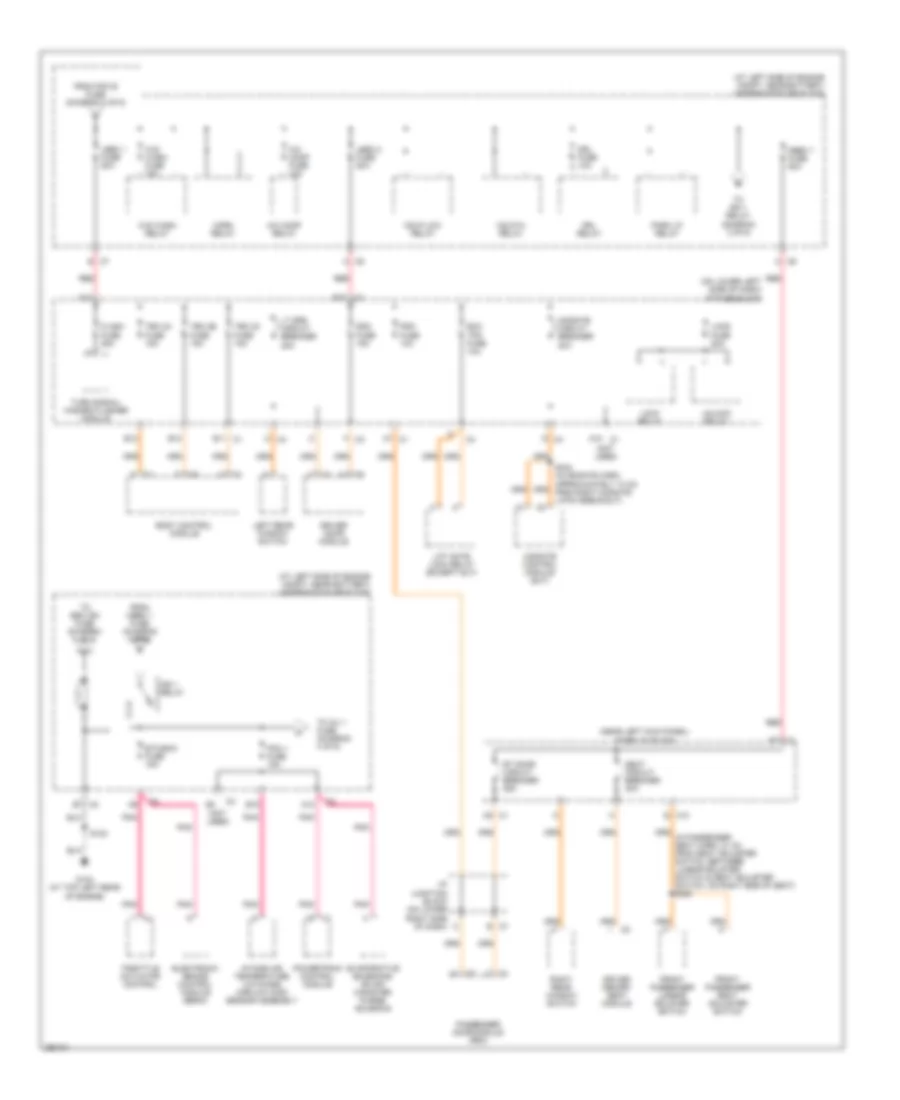 https://portal-diagnostov.com/license.html
Automotive Electricians Portal FZCO
Automotive Electricians Portal FZCO
https://portal-diagnostov.com/license.html
https://portal-diagnostov.com/license.html
Automotive Electricians Portal FZCO
Automotive Electricians Portal FZCOList of elements for Power Distribution Wiring Diagram (3 of 6) for Hummer H2 2007:
- (at left side of engine compt, near battery) underhood fuse block
- (near left kick panel) i/p relay block
- (not used)
- (on lower left side of dash)
- A c5
- A c6
- A/c comp fuse 10a
- A/c comp relay
- A10 c1
- A12
- A7 c1
- B c7
- B10
- B12
- B7 c2
- Body control module
- C9 c1
- Ddm fuse 15a
- Driver door module
- Driver memory seat module
- Drl fuse 10a
- Drl relay
- E c10
- E c7
- E10
- E11 c1
- E12
- Ecc tpm fuse 10a
- Electronic brake control module (ebcm)
- Etc/ecm fuse 15a
- Evaporative emissions (evap) canister purge solenoid
- F c3
- Flash fuse 25a
- From mbec 1 fuse (diagram 3 of 6)
- From pcm b fuse (diagram 2 of 6)
- Front passenger lumbar bolster switch
- Front passenger seat adjuster switch
- G c4
- G104 (at top left rear of engine)
- Hdlp-hi relay
- Hdlp-low relay
- Horn relay
- I/p fuse block
- I/p junction block (on lower right side of dash)
- Ign 1 relay
- Intake air temperature (iat)/mass airflow (maf) sensor assembly
- Lbec 1 fuse 50a
- Lbec 2 fuse 50a
- Lcks fuse 20a
- Left rear window switch
- Lift gate lock relay (except sut)
- Lock relay
- Lt drs circuit breaker 25a
- M c4
- Mbec 1 fuse 50a
- Midgate circuit breaker 20a
- Midgate control module (sut)
- Park lp relay
- Passenger door module (pdm)
- Pcm 1 fuse 15a
- Pdm fuse 10a
- Pnk
- Powertrain control module
- Red
- Right rear window switch
- Rt door circuit breaker 25a
- S102
- Seat circuit breaker 30a
- Tbc 2a fuse 15a
- Tbc 2b fuse 15a
- Tbc 2c fuse 15a
- Throttle actuator control
- To ign 1 relay (diagram 3 of 6)
- To inj 1 fuse (diagram 4 of 6)
- To seo ign fuse (diagram 6 of 6)
- Turn signal/ hazard flasher module
- Unlock relay
- W/s wash fuse 15a
- W/s wash relay
Power Distribution Wiring Diagram (4 of 6) for Hummer H2 2007
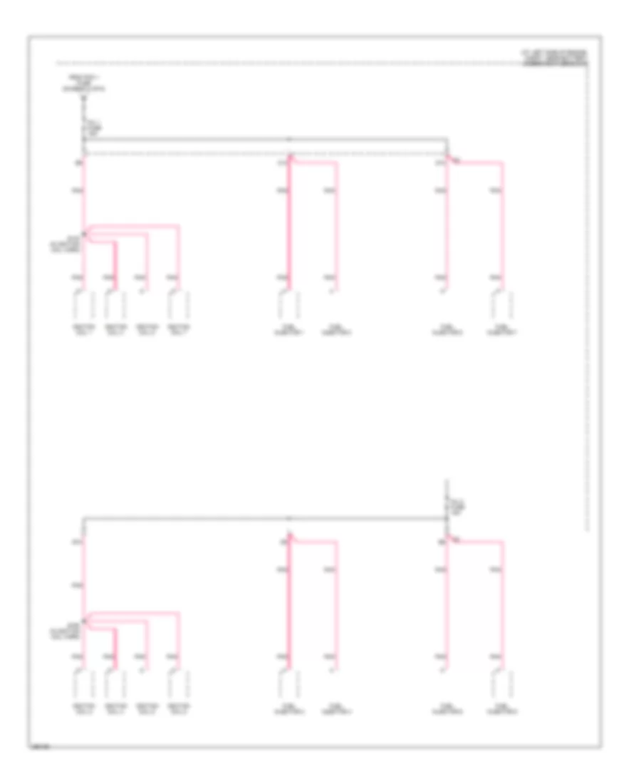 https://portal-diagnostov.com/license.html
Automotive Electricians Portal FZCO
Automotive Electricians Portal FZCO
https://portal-diagnostov.com/license.html
https://portal-diagnostov.com/license.html
Automotive Electricians Portal FZCO
Automotive Electricians Portal FZCOList of elements for Power Distribution Wiring Diagram (4 of 6) for Hummer H2 2007:
- (at left side of engine, compt, near battery) underhood fuse block
- C10
- D10
- E10
- From pcm 1 fuse (diagram 3 of 6)
- Fuel injector 1
- Fuel injector 2
- Fuel injector 3
- Fuel injector 4
- Fuel injector 5
- Fuel injector 6
- Fuel injector 7
- Fuel injector 8
- Ignition coil 1
- Ignition coil 2
- Ignition coil 3
- Ignition coil 4
- Ignition coil 5
- Ignition coil 6
- Ignition coil 7
- Ignition coil 8
- Inj 1 fuse 15a
- Inj 2 fuse 15a
- Pnk
- S140 (in ignition coil harn)
- S160 (in ignition coil harn)
Power Distribution Wiring Diagram (5 of 6) for Hummer H2 2007
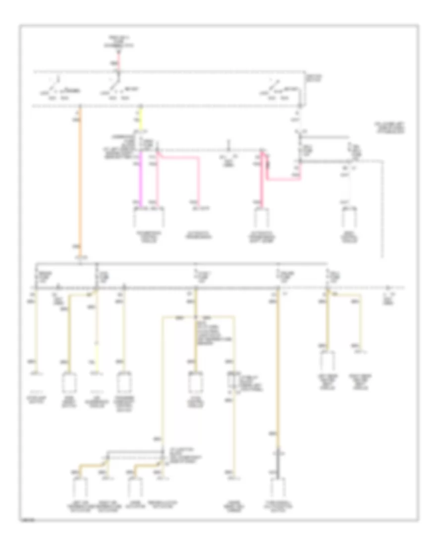 https://portal-diagnostov.com/license.html
Automotive Electricians Portal FZCO
Automotive Electricians Portal FZCO
https://portal-diagnostov.com/license.html
https://portal-diagnostov.com/license.html
Automotive Electricians Portal FZCO
Automotive Electricians Portal FZCOList of elements for Power Distribution Wiring Diagram (5 of 6) for Hummer H2 2007:
- (not used)
- (on lower left side of dash) i/p fuse block
- 4wd fuse 15a
- Acc
- Air suspension module
- Automatic transmission
- Automatic transmission shift lever
- Body control module
- Brake fuse 10a
- C1 e8
- C175
- C4 c
- Crnk fuse 10a
- Cruise fuse 10a
- E11
- F10
- From ign a fuse (diagram 1 of 6)
- Hvac 1 fuse 10a
- Hvac control module
- I/p junction block (on lower right side of dash)
- I/p relay block (near left kick panel)
- Ign 0 fuse 10a
- Ign 3 fuse 10a
- Ignition switch
- Inside rear view mirror
- Left air temperature actuator
- Left rear heated seat module
- Lock
- Mode actuator
- Nca
- Pnk
- Pnk pnk
- Powertrain control module
- Recirculation actuator
- Red
- Ride height switch
- Right air temperature actuator
- Right rear heated seat module
- Run
- S216 (in i/p harn, 2.5 cm from junction of air temperature sensor)
- Start
- Stoplamp switch
- Tbc ign 0 fuse 10a
- Transfer case shift control switch
- Turn signal/ multifunction switch
- Underhood fuse block (at left side of engine compt, near battery)
Power Distribution Wiring Diagram (6 of 6) for Hummer H2 2007
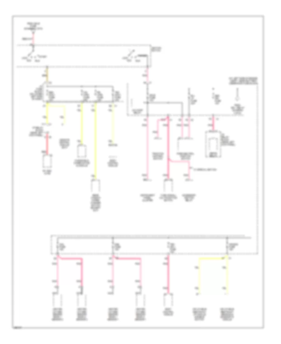 https://portal-diagnostov.com/license.html
Automotive Electricians Portal FZCO
Automotive Electricians Portal FZCO
https://portal-diagnostov.com/license.html
https://portal-diagnostov.com/license.html
Automotive Electricians Portal FZCO
Automotive Electricians Portal FZCOList of elements for Power Distribution Wiring Diagram (6 of 6) for Hummer H2 2007:
- (at left side of engine compt, near battery) underhood fuse block
- A/c comp relay
- Acc
- Accessory ignition relay
- Air bag fuse 15a
- B/u lp fuse 20a
- Body control module
- C1 b2
- C8 d
- D10
- Defog relay
- F11
- F8 c2
- From ign 1 relay (diagram 3 of 6)
- From ign b fuse (diagram 1 of 6)
- Heated oxygen sensor bank 1 sensor 1
- Heated oxygen sensor bank 1 sensor 2
- Heated oxygen sensor bank 2 sensor 1
- Heated oxygen sensor bank 2 sensor 2
- I/p fuse block (on lower left side of dash)
- I/p relay block (near left kick panel)
- Ign e fuse 10a
- Ignition switch
- Inflatable restraint i/p module disable switch
- Inflatable restraint sensing & diagnostic module
- Instrument panel cluster
- Lock
- Midgate control module (sut)
- Nca
- O2a fuse 15a
- O2b fuse 15a
- Park/neutral position switch
- Pnk
- R/v box (uwg)
- Rear window wiper/ washer switch (except sut)
- Red
- Rr wpr fuse 15a
- Run
- Seo accy fuse 10a
- Seo ign fuse 10a
- Start
- Tbc accy fuse 10a
- Tbc ign 1 fuse 10a
- Traction control switch
- Turn signal/ multifunction switch
- W/ special edition
- Windshield wiper motor & module
- Ws wpr fuse 25a
POWER DOOR LOCKS
Power Door Locks Wiring Diagram (1 of 2) for Hummer H2 2007
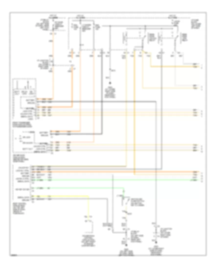 https://portal-diagnostov.com/license.html
Automotive Electricians Portal FZCO
Automotive Electricians Portal FZCO
https://portal-diagnostov.com/license.html
https://portal-diagnostov.com/license.html
Automotive Electricians Portal FZCO
Automotive Electricians Portal FZCOList of elements for Power Door Locks Wiring Diagram (1 of 2) for Hummer H2 2007:
- A12
- A2 c1
- A4 c1
- A7 c1
- B10
- B12
- Batt volt
- Battery
- Body control module (bcm) (on top left side of dash, above i/p fuse block)
- C3 d
- Ddm fuse 15a
- Dr lock
- Dr un- lock
- Dr unlock
- Driver door module (ddm) (behind driver's door panel)
- Front passenger door module (fpdm) (in passenger door)
- G200 (on left side of dash, near left kick panel)
- G203 (at lower right side of dash, near right kick panel)
- Ground
- Hot at all times
- Hot at all times all times
- I/p fuse block (on lower left side of dash)
- I/p junction block (on lower right side of dash)
- I/p relay block (on left side of dash, near left kick panel)
- Ign key sw sig
- Ignition key alarm switch (on ignition key cylinder)
- Lgate lk ctrl
- Lock ctrl
- Lock rly ctrl
- Locks fuse 20a
- Logic
- Lt doors circuit breaker 25a
- Pdm fuse 10a
- Powertrain control module (pcm) (on left front of engine compartment)
- Rear door lock relay
- Rear door unlock relay
- Rt door circuit breaker 25a
- S213
- S219
- Serial data
- Tan
- Unlock ctrl
- Unlock rly
Power Door Locks Wiring Diagram (2 of 2) for Hummer H2 2007
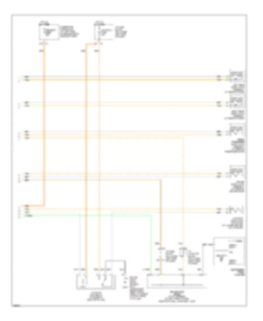 https://portal-diagnostov.com/license.html
Automotive Electricians Portal FZCO
Automotive Electricians Portal FZCO
https://portal-diagnostov.com/license.html
https://portal-diagnostov.com/license.html
Automotive Electricians Portal FZCO
Automotive Electricians Portal FZCOList of elements for Power Door Locks Wiring Diagram (2 of 2) for Hummer H2 2007:
- D12 c1
- Door lock actuator
- Driver door latch assembly (at rear of driver door)
- Front front passenger passenger door latch assembly (at rear of passenger door)
- G410
- Hot at all times
- Hot at all times all times
- I/p fuse block (on lower left side c1 of dash)
- I/p fuse block (on lower left side of dash)
- I/p junction block (on lower right side of dash)
- Ign
- Instrument instrument panel panel cluster cluster
- Left rear door latch assembly (at rear of door)
- Lgate rly fuse 10a
- Liftgate door lock actuator (at lower center of liftgate)
- Liftgate lock relay (at base of right "b" pillar)
- Logic
- Right rear door latch assembly (at rear of door)
- Security ind
- Serial data
- Splice pack sp410 (except sut) (inside right rear cargo area, at middle of right rear "d" pillar)
- Splice pack splice pack sp205 sp205 (in i/p harness, on left side of dash, near footwell courtesy lamp)
- Tan
- Tan tan
- Tbc batt tbc batt fuse fuse 10a 10a
- Underhood fuse block (at left side of engine compt, near battery)
POWER MIRRORS
Electrochromic Mirror Wiring Diagram for Hummer H2 2007
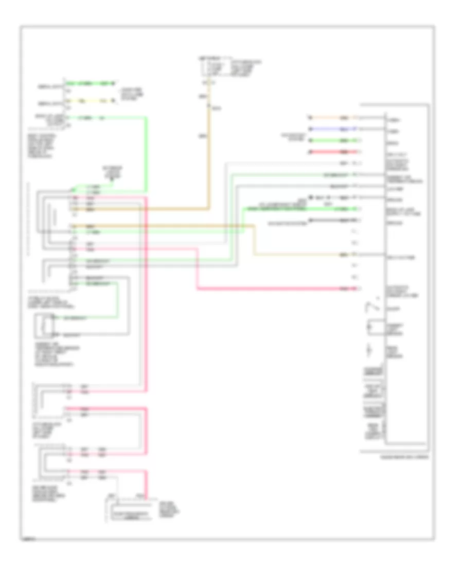 https://portal-diagnostov.com/license.html
Automotive Electricians Portal FZCO
Automotive Electricians Portal FZCO
https://portal-diagnostov.com/license.html
https://portal-diagnostov.com/license.html
Automotive Electricians Portal FZCO
Automotive Electricians Portal FZCOList of elements for Electrochromic Mirror Wiring Diagram for Hummer H2 2007:
- Amb air temp display
- Ambient air temperature sensor (at right front of vehicle, to right of radiator support)
- Ambient air temperature sig
- Ambient light sensor
- Automatic day/night mirror low ref
- Automatic day/night mirror sig
- B12
- Back up lamp voltage output c5
- Body control module (bcm) (on top left side of dash, above i/p fuse block)
- Compass display
- Computer data lines system
- D3 c1
- Drain
- Driver door module (ddm) (behind driver's door panel)
- Driver outside rearview mirror
- Electro- chromic mirror
- Electrochromic mirror
- Exterior lights system
- G203 (at lower right side of dash, near right kick panel)
- Ground
- Hot in run
- Hvac 1 fuse 10a
- I/p fuse block (on lower left side of dash)
- I/p relay block (under left side of dash, near kick panel)
- Ign 3 volt
- Ign 3 voltage
- Inside rearview mirror
- Low ref
- Navigation system
- On/off
- Pnk
- Rear light sensor
- Rear view camera display
- Red
- S216
- S301
- Serial data
- Video+
- Video-
POWER SEATS
Front Seat Heater Wiring Diagram for Hummer H2 2007
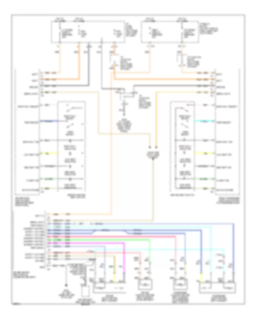 https://portal-diagnostov.com/license.html
Automotive Electricians Portal FZCO
Automotive Electricians Portal FZCO
https://portal-diagnostov.com/license.html
https://portal-diagnostov.com/license.html
Automotive Electricians Portal FZCO
Automotive Electricians Portal FZCOList of elements for Front Seat Heater Wiring Diagram for Hummer H2 2007:
- (in driver seat jumper harn, 4.5 cm from memory seat module c3)
- 570a
- Back only ind
- Back only indicator
- Back only select
- Batt
- Batt (+)
- C1 a7
- C1 c9
- C10 h
- C2 f
- C3 d
- C4 a
- C7 c
- C7 e
- Computer data lines system
- Ddm fuse 15a
- Driver back heated seat element
- Driver cushion heated seat element (in driver seat)
- Driver door module (ddm) (behind driver's door panel)
- Driver memory seat module (under driver seat)
- Driver seat recline position sensor
- Element control
- Front passenger door module (pdm) (in passenger door)
- G203 (at lower right side of dash, near right kick panel)
- G302 (at left inner center "b" pillar)
- Gnd
- Ground
- Heated seat switch
- Hi heat ind
- High heat indicator
- Hot at all times
- I/p fuse block (on lower left side of dash)
- I/p junction block (on lower right side of dash)
- I/p relay block (on left side of dash, near left kick panel)
- Low heat ind
- Low heat indicator
- Low ref
- Lt doors circuit breaker 25a
- Med heat ind
- Med heat indicator
- Memory/heated seat switch
- Nca
- Passenger back heated seat element
- Passenger cushion heated seat element (in passenger seat cushion)
- Pdm fuse 15a
- Pnk
- Rt doors circuit breaker 25a
- S213
- S328
- Seat circuit breaker 30a
- Serial data
- Switch power
- Tan
- Temp select
- Temp signal
Lumbar Wiring Diagram for Hummer H2 2007
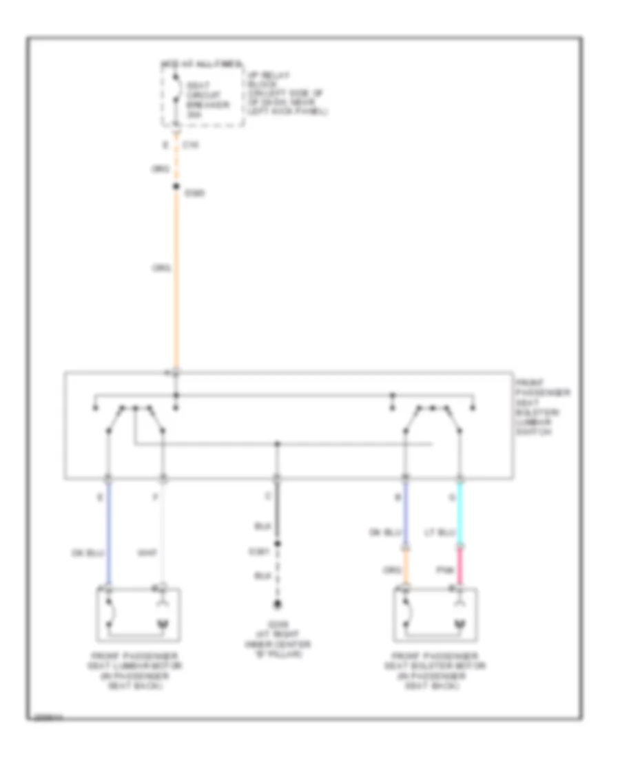 https://portal-diagnostov.com/license.html
Automotive Electricians Portal FZCO
Automotive Electricians Portal FZCO
https://portal-diagnostov.com/license.html
https://portal-diagnostov.com/license.html
Automotive Electricians Portal FZCO
Automotive Electricians Portal FZCOList of elements for Lumbar Wiring Diagram for Hummer H2 2007:
- C10
- Front passenger seat bolster motor (in passenger seat back)
- Front passenger seat bolster/ lumbar switch
- Front passenger seat lumbar motor (in passenger seat back)
- G306 (at right inner center "b" pillar)
- Hot at all times
- I/p relay block (on left side of of dash, near left kick panel)
- Pnk
- S380
- S381
- Seat circuit breaker 30a
Passenger Power Seat Wiring Diagram for Hummer H2 2007
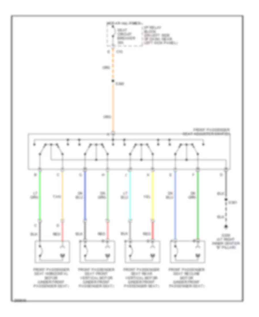 https://portal-diagnostov.com/license.html
Automotive Electricians Portal FZCO
Automotive Electricians Portal FZCO
https://portal-diagnostov.com/license.html
https://portal-diagnostov.com/license.html
Automotive Electricians Portal FZCO
Automotive Electricians Portal FZCOList of elements for Passenger Power Seat Wiring Diagram for Hummer H2 2007:
- C10
- Front passenger seat adjuster switch
- Front passenger seat front vertical motor (under front passenger seat)
- Front passenger seat horizontal motor (under front passenger seat)
- Front passenger seat rear vertical motor (under front passenger seat)
- Front passenger seat recline motor (under front passenger seat)
- G306 (at right inner center "b" pillar)
- Hot at all times
- I/p relay block (on left side of dash, near left kick panel)
- Red
- S380
- S381
- Seat circuit breaker 30a
- Tan
Rear Seat Heater Wiring Diagram for Hummer H2 2007
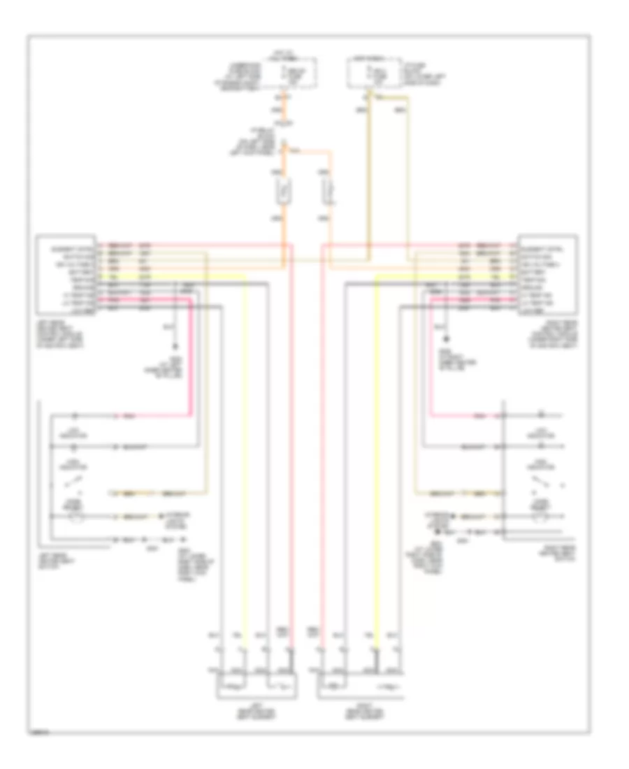 https://portal-diagnostov.com/license.html
Automotive Electricians Portal FZCO
Automotive Electricians Portal FZCO
https://portal-diagnostov.com/license.html
https://portal-diagnostov.com/license.html
Automotive Electricians Portal FZCO
Automotive Electricians Portal FZCOList of elements for Rear Seat Heater Wiring Diagram for Hummer H2 2007:
- A element cntrl
- B switch sig
- Battery
- C ign voltage 3
- C1 e4
- C1 f7
- C10
- D battery
- E temp sig
- Element cntrl
- F ground
- G hi temp ind
- G203 (at lower right side of dash, near right kick panel)
- G302 (at left inner center "b" pillar)
- G306 (at right inner center "b" pillar)
- Ground
- H lo temp ind
- Hi temp ind
- High indicator
- Hot at all times
- Hot in run
- I/p fuse block (on lower left side of dash)
- I/p relay block (on left side of dash, near left kick panel)
- Ign 3 fuse 10a
- Ign voltage 3
- Interior lights system
- J low ref
- Left rear heated seat control module (under left side of 2nd row seat)
- Left rear heated seat element
- Left rear heated seat switch
- Lo temp ind
- Low indicator
- Low ref
- Mode select
- Nca
- Pnk
- Right rear heated seat control module (under right side of 2nd row seat)
- Right rear heated seat element
- Right rear heated seat switch
- S306
- S351
- S393
- Seo b1 fuse 15a
- Switch sig
- Temp sig
- Underhood fuse block (at left side of engine compt, near battery)
POWER TOP/SUNROOF
Power Top/Sunroof Wiring Diagram for Hummer H2 2007
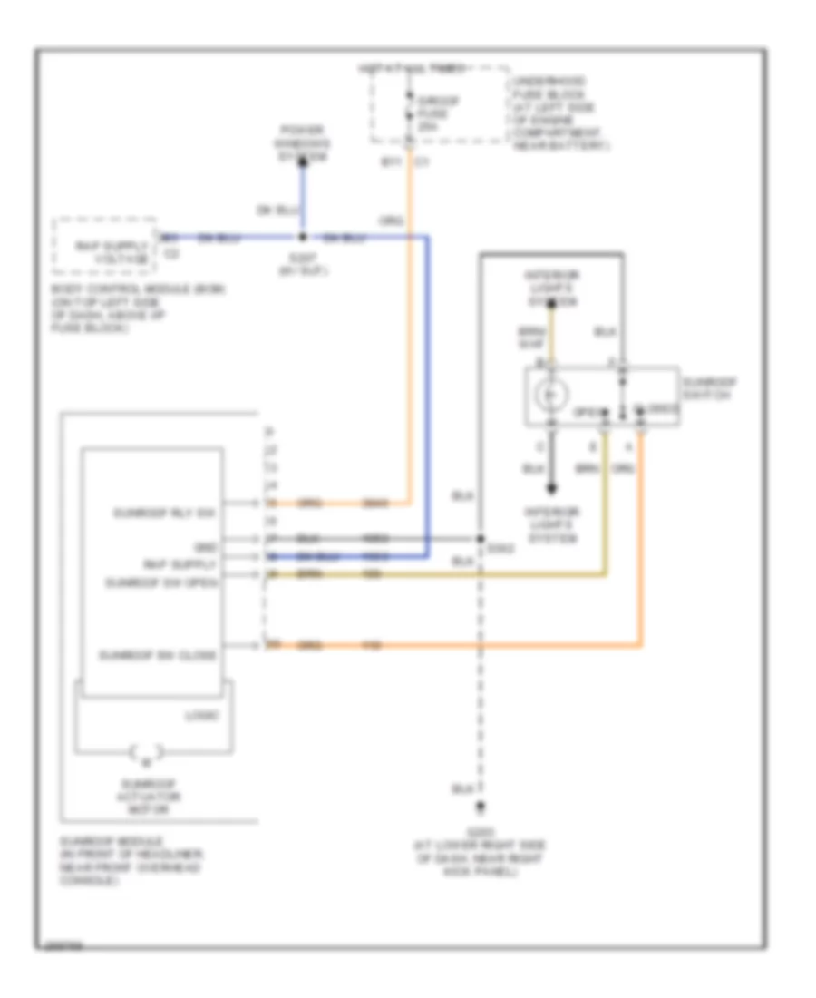 https://portal-diagnostov.com/license.html
Automotive Electricians Portal FZCO
Automotive Electricians Portal FZCO
https://portal-diagnostov.com/license.html
https://portal-diagnostov.com/license.html
Automotive Electricians Portal FZCO
Automotive Electricians Portal FZCOList of elements for Power Top/Sunroof Wiring Diagram for Hummer H2 2007:
- B11
- Body control module (bcm) (on top left side of dash, above i/p fuse block)
- Closed
- G203 (at lower right side of dash, near right kick panel)
- Gnd
- Hot at all times
- Interior lights system
- Logic
- Open
- Power windows system
- S/roof fuse 25a
- S207 (w/ sut)
- S302
- Sunroof actuator motor
- Sunroof module (in front of headliner, near front overhead console)
- Sunroof rly sw
- Sunroof sw close
- Sunroof sw open
- Sunroof switch
- Underhood fuse block (at left side of engine compartment, near battery)
POWER WINDOWS
Power Windows Wiring Diagram (1 of 2) for Hummer H2 2007
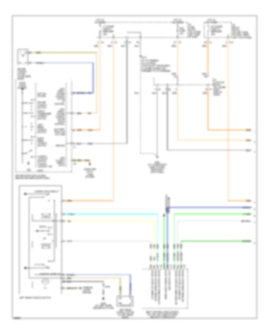 https://portal-diagnostov.com/license.html
Automotive Electricians Portal FZCO
Automotive Electricians Portal FZCO
https://portal-diagnostov.com/license.html
https://portal-diagnostov.com/license.html
Automotive Electricians Portal FZCO
Automotive Electricians Portal FZCOList of elements for Power Windows Wiring Diagram (1 of 2) for Hummer H2 2007:
- (in i/p harness, 45.4 cm from junction of instrument
- B12
- Battery positive voltage
- Bcm class 2 serial data
- Body control module (bcm) (on top left side of dash, above i/p fuse block)
- C c3
- C1 a7
- C4 a
- C4 m
- C9 c1
- Cluster connector harness to i/p harness)
- Computer data lines system
- D c3
- Ddm class 2 serial data
- Door locks system
- Down
- Driver door module (ddm) (behind driver's door panel)
- Driver window motor (in driver's door)
- Driver window switch
- E c7
- F c2
- Front passenger window switch
- G203 (at lower right side of dash, near right kick panel)
- G302 (at left inner center "b" pillar)
- Ground
- Hot at all times
- I/p fuse block (on lower left side of dash
- I/p junction block (on lower right side of dash)
- I/p relay block (on left side of dash, near left kick panel)
- Ill
- Interior lights system
- K c10
- Led
- Left front power window motor down control
- Left front power window motor up control
- Left rear window motor (in left rear door)
- Left rear window switch
- Logic
- Lr pwr wndo lockout cntrl
- Lr wndo dwn relay cntrl
- Lr wndo up relay cntrl
- Lt doors circuit breaker 25a
- Pdm fuse 15a
- Right rear window switch
- Rr pwr wndo lockout cntrl
- Rr wndo dwn relay cntrl
- Rr wndo up relay cntrl
- Rt doors circuit breaker 25a
- S213
- S720
- Switch power
- Window down relay
- Window lockout ind
- Window lockout switch
- Window up relay
Power Windows Wiring Diagram (2 of 2) for Hummer H2 2007
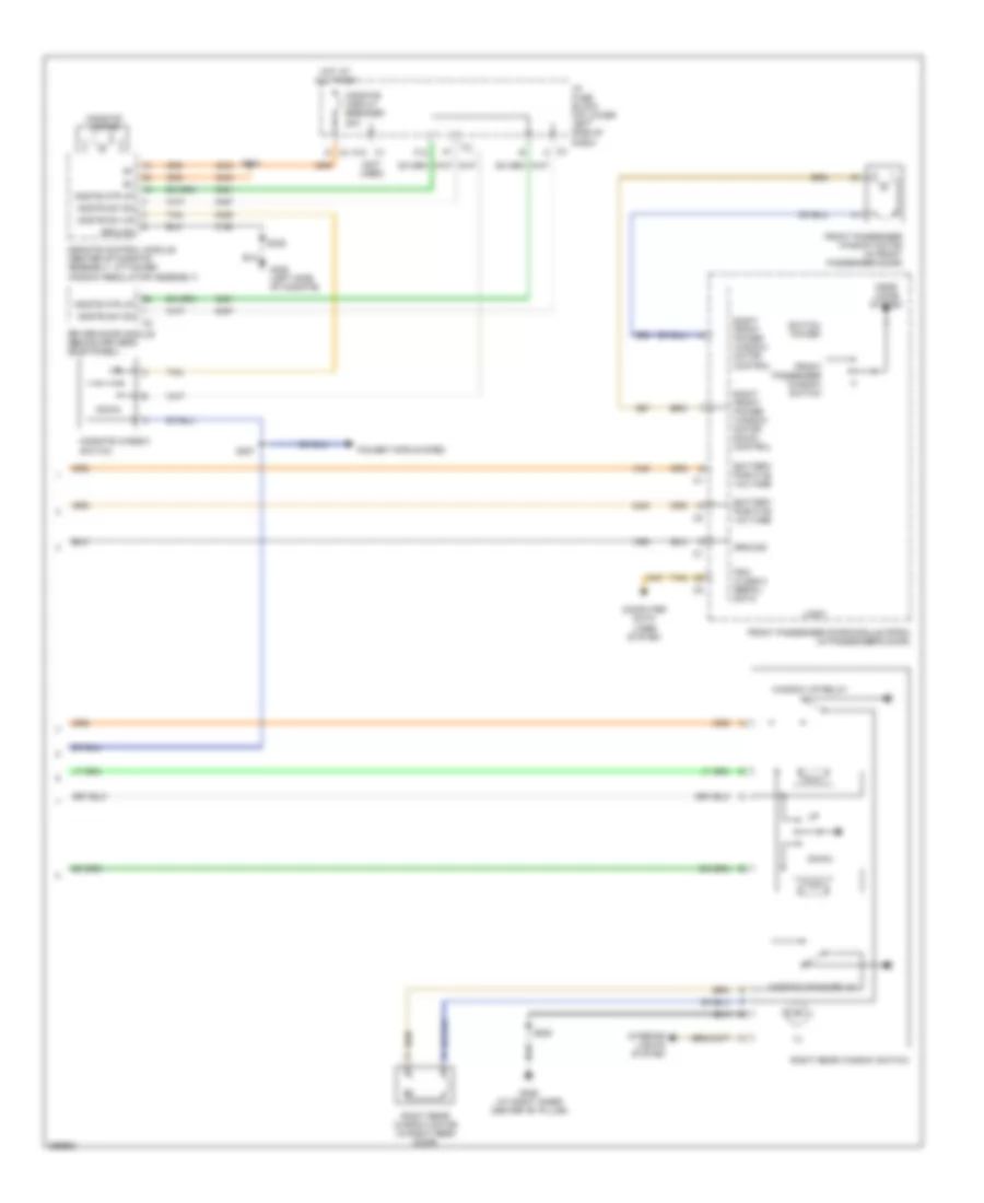 https://portal-diagnostov.com/license.html
Automotive Electricians Portal FZCO
Automotive Electricians Portal FZCO
https://portal-diagnostov.com/license.html
https://portal-diagnostov.com/license.html
Automotive Electricians Portal FZCO
Automotive Electricians Portal FZCOList of elements for Power Windows Wiring Diagram (2 of 2) for Hummer H2 2007:
- (not used)
- Battery positive voltage
- C1 a10
- C3 a
- C4 g
- Computer data lines system
- Door locks system
- Down
- Driver door module (behind driver's door panel)
- F12
- Front passenger door module (fpdm) (in passenger's door)
- Front passenger window motor (in front passenger door)
- Front passenger window switch
- G306 (at right inner center "b" pillar)
- G320 (left side of midgate)
- Ground
- Hot at all times
- I/p fuse block (on lower left side of dash)
- Ill
- Interior lights system
- Logic
- Mdgte mtr up
- Mdgte sw dn
- Mdgte sw up
- Midgate circuit breaker 20a
- Midgate control module (center of midgate assembly, attached window regulator assembly)
- Midgate motor
- Midgate window switch
- Pdm class 2 serial data
- Power tops system
- Right front power window motor control
- Right front power window motor down control
- Right rear window motor (in right rear door)
- Right rear window switch
- S207
- S334
- S339
- S820
- Switch power
- Tan
- Window down relay
- Window up relay
RADIO
Radio Wiring Diagram (1 of 2) for Hummer H2 2007
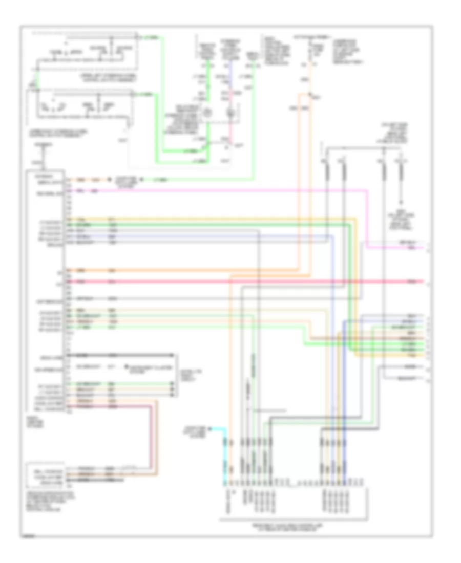 https://portal-diagnostov.com/license.html
Automotive Electricians Portal FZCO
Automotive Electricians Portal FZCO
https://portal-diagnostov.com/license.html
https://portal-diagnostov.com/license.html
Automotive Electricians Portal FZCO
Automotive Electricians Portal FZCOList of elements for Radio Wiring Diagram (1 of 2) for Hummer H2 2007:
- (on left side of dash, near left kick panel) i/p relay block
- 12v
- A10
- A11
- A12
- Amp sens sig
- Antenna
- Audio common
- B10
- B11
- B12
- B31
- Bare
- Body control module (bcm) (on top left side of dash, above i/p fuse block)
- C206
- C277
- Cell voice sig
- Coax
- Computer data lines system
- Drain wire
- G200 (on left side of dash, near left kick panel)
- Ground
- Hot at all times
- Inflatable restraint steering wheel module coil (on steering column, behind steering wheel)
- Instrument cluster system
- Lf aud sig +
- Lf aud sig -
- Lr aud sig +
- Lr aud sig -
- Lt aud sig +
- Pnk
- Prog
- Radio (center of dash)
- Radio fuse 15a
- Rear seat audio (rsa) controller (at rear of center console)
- Remote radio control signal
- Rf aud sig +
- Rf aud sig -
- Rr aud sig +
- Rr aud sig -
- Rsa enbl sig
- Rt aud sig +
- S201
- Satellite radio circuit
- Seek dn
- Seek up
- Serial data
- Shield
- Source dn
- Source up
- Tan
- Underhood fuse block (at left side of engine compt, near battery)
- Upper left steering wheel control switch assembly
- Upper right steering wheel control switch assembly
- Veh speed sig
- Vehicle communication interface module (vcim) (at center of dash, below hvac control module)
- Voice
- Voice low ref
- Vol dn
- Vol up
Radio Wiring Diagram (2 of 2) for Hummer H2 2007
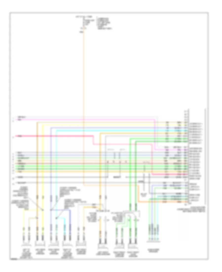 https://portal-diagnostov.com/license.html
Automotive Electricians Portal FZCO
Automotive Electricians Portal FZCO
https://portal-diagnostov.com/license.html
https://portal-diagnostov.com/license.html
Automotive Electricians Portal FZCO
Automotive Electricians Portal FZCOList of elements for Radio Wiring Diagram (2 of 2) for Hummer H2 2007:
- (in body harness approximately 10 cm from c375 breakout) s333
- (in body harness approximately 12 cm from c320 breakout) s330
- (in body harness approximately 16.5 cm from c375 breakout) s332
- (in body harness approximately 22 cm from c320 breakout)
- A10
- A11
- A12
- Amp sens sig
- Audio amplifier (under front floor console, between front seats)
- B10
- B11
- B12
- Bare
- Drain wire
- Ground
- Hot at all times
- I/p fuse block (on lower left side g of dash)
- I/p junction block (on lower right side of dash)
- L spk out+
- L spk out-
- Left "d" pillar twiddler speaker (except sut)
- Left front door speaker
- Left front tweeter speaker
- Left rear door speaker
- Lf aud sig +
- Lf aud sig -
- Lf spkr out +
- Lf spkr out -
- Lr aud sig +
- Lr aud sig -
- Lr spkr out +
- Lr spkr out -
- Nca
- Pnk
- R spk out+
- R spk out-
- Radio amp fuse 30a
- Radio on sig
- Rf aud sig +
- Rf aud sig -
- Rf spkr out +
- Rf spkr out -
- Right "d" pillar twiddler speaker (except sut)
- Right front door speaker
- Right front tweeter speaker
- Right rear door speaker
- Rr aud sig +
- Rr aud sig -
- Rr spkr out +
- Rr spkr out -
- Rsa enbl sig
- S331
- Subwoofer speaker
- Tan
- Tan b
- Underhood fuse block (at left side of engine compt, near battery)
Satellite Radio Wiring Diagram for Hummer H2 2007
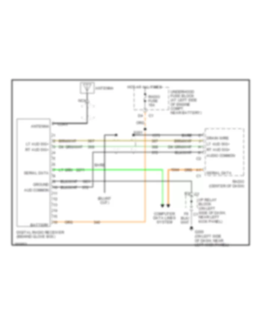 https://portal-diagnostov.com/license.html
Automotive Electricians Portal FZCO
Automotive Electricians Portal FZCO
https://portal-diagnostov.com/license.html
https://portal-diagnostov.com/license.html
Automotive Electricians Portal FZCO
Automotive Electricians Portal FZCOList of elements for Satellite Radio Wiring Diagram for Hummer H2 2007:
- Antenna
- Aud common
- Audio common
- Bare
- Battery
- Coax
- Computer data lines system
- Digital radio receiver (behind glove box)
- Drain wire
- G200 (on left side of dash, near left kick panel)
- Ground
- Hot at all times
- I/p relay block (on left side of dash, c1 near left kick panel)
- Lt aud sig+
- Nca
- Radio (center of dash)
- Radio fuse 15a
- Rt aud sig+
- S201
- Serial data
- Underhood fuse block (at left side of engine compt, near battery)
Video Display Wiring Diagram for Hummer H2 2007
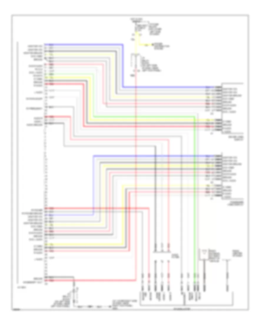 https://portal-diagnostov.com/license.html
Automotive Electricians Portal FZCO
Automotive Electricians Portal FZCO
https://portal-diagnostov.com/license.html
https://portal-diagnostov.com/license.html
Automotive Electricians Portal FZCO
Automotive Electricians Portal FZCOList of elements for Video Display Wiring Diagram for Hummer H2 2007:
- (at lower right side of dash, near right kick panel) g203
- A/v box
- Accessory volt
- Audio filter
- Audio ground
- Audio l
- Audio r
- Coax
- D video
- Driver video display
- Dvd l audio
- Dvd r audio
- Dvd video
- F11 c1
- Fm clk
- Fm data
- Fm frequency
- Fm modulator
- Fm power
- Fm power ground
- Fm pwr on/off
- Ground
- Hot in acc or run
- I/p fuse block (on lower left side of dash)
- I/p relay block (on left side of dash, near left kick panel)
- I/p relay block (on left side of dash, near left kick panel) c8
- L audio
- Monitor ground
- Monitor vcc
- Nca audio ground
- Nca audio l
- Nca audio r
- Nca d video
- Nca d video nca ground nca r audio nca l audio
- Nca dvd l audio
- Nca dvd r audio
- Nca dvd video
- Nca fm clk
- Nca fm data
- Nca fm frequency
- Nca fm pwr
- Nca fm pwr gnd
- Nca fm pwr on/off
- Nca ground
- Nca l audio
- Nca monitor ground
- Nca monitor vcc
- Nca monitor vcc nca monitor vcc nca monitor ground nca dvd video nca ground nca dvd r audio nca ground nca dvd l audio
- Nca r audio
- Passenger video display
- Power distribution system
- R audio
- Radio (center of dash)
- Radio antenna (at right front of vehicle)
- Red
- S213
- Seo accy fuse 21 10a
SHIFT INTERLOCK
Ignition Lock Solenoid Wiring Diagram for Hummer H2 2007
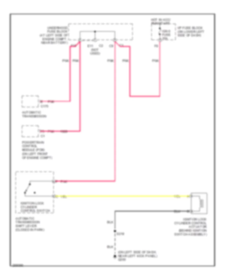 https://portal-diagnostov.com/license.html
Automotive Electricians Portal FZCO
Automotive Electricians Portal FZCO
https://portal-diagnostov.com/license.html
https://portal-diagnostov.com/license.html
Automotive Electricians Portal FZCO
Automotive Electricians Portal FZCOList of elements for Ignition Lock Solenoid Wiring Diagram for Hummer H2 2007:
- (not used)
- (on left front of engine compt)
- (on left side of dash, near left kick panel) g200
- Automatic transmission
- Automatic transmission shift lever (closed in park)
- C175
- E11
- F10
- Hot in acc/ run/start
- I/p fuse block (on lower left side of dash)
- Ign 0 fuse 10a
- Ignition lock cylinder control actuator (behind ignition switch assembly)
- Ignition lock cylinder control switch
- Pnk
- Powertrain control module (pcm)
- S218
- Underhood fuse block (at left side of engine compt, near battery)
Shift Interlock Wiring Diagram for Hummer H2 2007
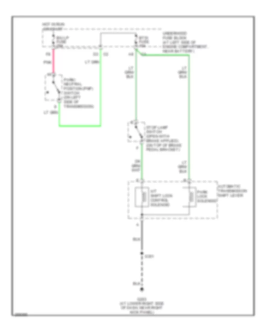 https://portal-diagnostov.com/license.html
Automotive Electricians Portal FZCO
Automotive Electricians Portal FZCO
https://portal-diagnostov.com/license.html
https://portal-diagnostov.com/license.html
Automotive Electricians Portal FZCO
Automotive Electricians Portal FZCOList of elements for Shift Interlock Wiring Diagram for Hummer H2 2007:
- A/t shift lock control solenoid
- Automatic transmission shift lever
- B/u lp fuse 20a
- Btsi fuse 10a
- G203 (at lower right side of dash, near right kick panel)
- Hot in run or start
- Park lock solenoid
- Park/ neutral position (pnp) switch (on left side of transmission)
- Pnk
- S351
- Underhood fuse block (at left side of engine compartment, near battery)
STARTING/CHARGING
Charging Wiring Diagram for Hummer H2 2007
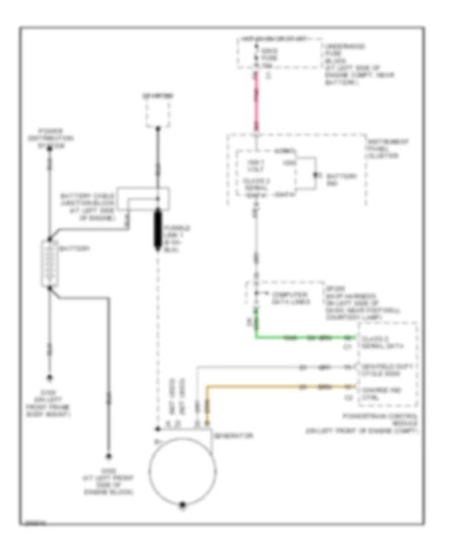 https://portal-diagnostov.com/license.html
Automotive Electricians Portal FZCO
Automotive Electricians Portal FZCO
https://portal-diagnostov.com/license.html
https://portal-diagnostov.com/license.html
Automotive Electricians Portal FZCO
Automotive Electricians Portal FZCOList of elements for Charging Wiring Diagram for Hummer H2 2007:
- (not used)
- Battery
- Battery cable junction block (at left side of engine)
- Battery ind
- Charge ind ctrl
- Class 2 serial data
- Computer data lines
- Data
- G100 (on left front frame body mount)
- G102 (at left front side of engine block)
- Gen field duty cycle sign
- Generator
- Hot in on or start
- Ign
- Ign 1 volt
- Ign e fuse 10a
- Instrument panel cluster
- Logic
- Pnk
- Power distribution system
- Powertrain control module (on left front of engine compt)
- Sp205 (in i/p harness, on left side of dash, near footwell courtesy lamp)
- Starter
- Underhood fuse block (at left side of engine compt, near battery)
Starting Wiring Diagram for Hummer H2 2007
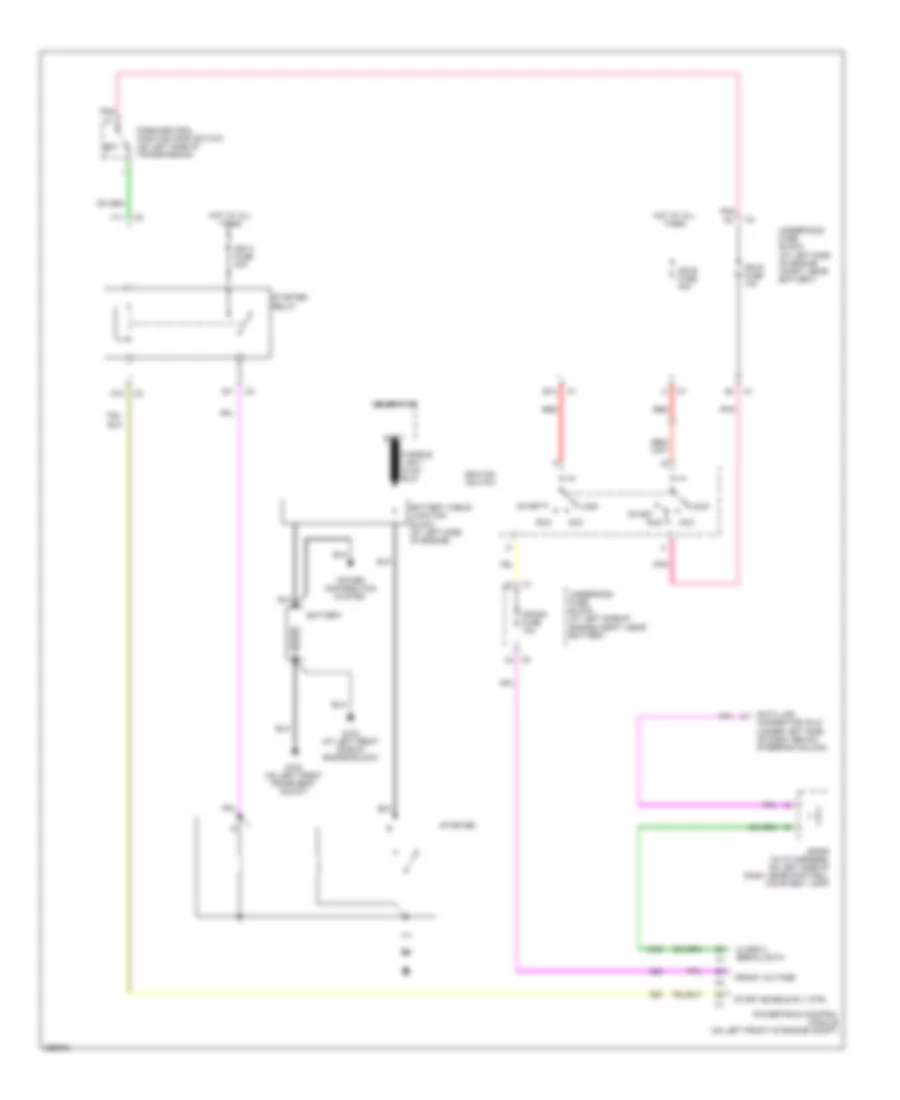 https://portal-diagnostov.com/license.html
Automotive Electricians Portal FZCO
Automotive Electricians Portal FZCO
https://portal-diagnostov.com/license.html
https://portal-diagnostov.com/license.html
Automotive Electricians Portal FZCO
Automotive Electricians Portal FZCOList of elements for Starting Wiring Diagram for Hummer H2 2007:
- Acc
- B12
- Batt
- Battery
- Battery cable junction block (at left side of engine)
- C2 f3
- Class 2 serial data
- Crank fuse 10a
- Crank voltage
- D11
- D12
- Data link connector (dlc) (under left side of dash, below steering column)
- F11
- G100 (on left front frame body mount)
- G102 (at left front side of engine block)
- Generator
- Hot at all times
- Ign a fuse 40a
- Ign b fuse 40a
- Ign e fuse 10a
- Ignition switch
- Lock
- P/n
- Park/neutral position (pnp) switch (on left side of transmission)
- Pnk
- Power distribution system
- Powertrain control module (on left front of engine compt)
- Red
- Run
- Sp205 (in i/p harness, on left side of dash, near footwell courtesy lamp)
- Start
- Start enable rly ctrl
- Starter
- Starter relay
- Underhood fuse block (at left side of engine compt, near battery)
SUPPLEMENTAL RESTRAINTS
Supplemental Restraints Wiring Diagram for Hummer H2 2007
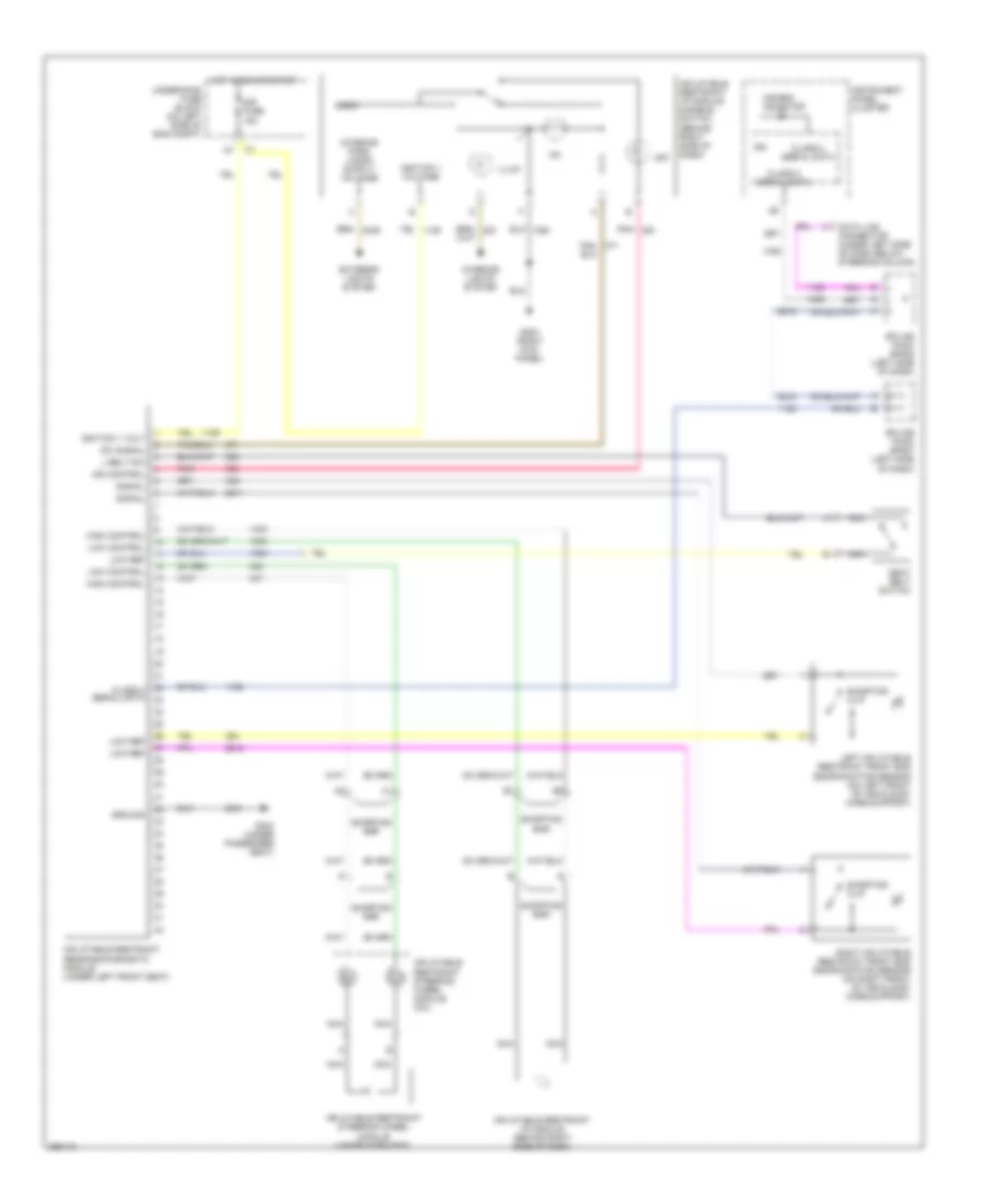 https://portal-diagnostov.com/license.html
Automotive Electricians Portal FZCO
Automotive Electricians Portal FZCO
https://portal-diagnostov.com/license.html
https://portal-diagnostov.com/license.html
Automotive Electricians Portal FZCO
Automotive Electricians Portal FZCOList of elements for Supplemental Restraints Wiring Diagram for Hummer H2 2007:
- Air bag indicator
- Class 2 serial data
- Data link connector (under left side of dash below steering column)
- Exterior lights system
- G203 (right kick panel)
- G304 (under passenger seat)
- Ground
- High control
- Hot in run or start
- Ign
- Ignition 1 volt
- Ignition 1 voltage
- Illum
- Ind control
- Inflatable restraint i/p module (behind right side of dash)
- Inflatable restraint i/p module disable switch (behind right side of dash)
- Inflatable restraint sensing/diagnostic module (under left front seat)
- Inflatable restraint steering wheel module (under horn pad)
- Inflatable restraint steering wheel module coil
- Instrument panel cluster
- Interior lights system
- L belt sw
- Left inflatable restraint front end discriminating sensor (on left front of vehicle by core support)
- Logic
- Low control
- Low ref
- Nca
- Off
- Pnk
- Right inflatable restraint front end discriminating sensor (on right front of vehicle by core support)
- Seat belt switch
- Shorting bar
- Shorting clip
- Signal
- Sir fuse 15a
- Splice pack sp205 (left side of dash)
- Splice pack sp207 (left side of dash)
- Sw signal
- Tan/
- Underhood fuse block (on left side of eng compt)
TRANSMISSION
A/T Wiring Diagram for Hummer H2 2007
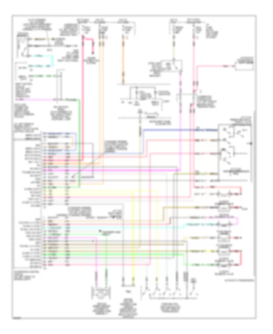 https://portal-diagnostov.com/license.html
Automotive Electricians Portal FZCO
Automotive Electricians Portal FZCO
https://portal-diagnostov.com/license.html
https://portal-diagnostov.com/license.html
Automotive Electricians Portal FZCO
Automotive Electricians Portal FZCOList of elements for A/T Wiring Diagram for Hummer H2 2007:
- (at left rear of engine compt) throttle actuator control module
- (at top right rear of engine) g103
- (in engine harness, 10 cm from junction of fuel injector 3 harness to engine harness) s103
- (in engine harness, 30 cm from junction of fuel injector 3 harness to engine harness)
- (in i/p harness, 45.4 cm from junction of instrument cluster connector harness to i/p harness)
- (not used)
- 1-2 shift solenoid valve
- 1-2 ss vlv ctrl
- 2-3 shift solenoid valve
- 2-3 ss vlv ctrl
- 3-2 shift solenoid valve
- 3-2 ss vlv ctrl
- 4wd low sig
- A/t fluid pressure manual manual valve position switch
- A/t fluid temperature sensor
- A12
- Abs/ tcc switch
- Automatic transmission
- Automatic transmission shift lever
- B11
- B12
- Body control module (on top left side of dash, above i/p fuse block)
- Brake fuse 10a
- C12
- Class 2 data
- Data link connector (under left side of dash, below steering column)
- Ect sig
- Engine coolant temperature sensor (near rear of engine block, below exhaust manifold)
- F10
- G203 (at lower right side of dash, near right kick panel)
- Gnd
- Hot at all times
- Hot in run
- Hot in run & start
- Hot in run, acc & start
- I/p fuse block (on lower left side of dash)
- Ign
- Ign 0 fuse 10a
- Ign 1 volt
- Ing 0 volt
- Instrument panel cluster (ipc)
- Interior lights system
- Ipc logic
- Ipc/dic fuse 10a
- Logic
- Low ref
- Mal- function indicator lamp
- Mil ctrl
- Park/neutral
- Pc sol hi ctrl
- Pc sol low ctrl
- Pc solenoid valve
- Pcm 1 fuse 15a
- Pcm b fuse 20a
- Pnk
- Pnk c
- Position switch (on left side of transmission)
- Power distribution system
- Powertrain control module (on left front of engine compt)
- Prnd321
- Red
- Red a
- Red b
- Rev
- S104
- S125
- S213
- Serial data
- Splice pack sp205 (in i/p harness, on left side of dash, near footwell courtesy lamp)
- Stop lamp switch (on top of brake pedal bracket)
- Sw sig
- Sw sig a
- Sw sig b
- Sw sig c
- Sw sig p
- Switch sig b
- Switch sig c
- Tcc brk sw sig
- Tcc pwm solenoid valve
- Tcc pwm vlv ctrl
- Tcc sol vlv ctrl
- Tcc solenoid valve
- Tft sens sig
- Tow/haul indicator
- Tow/haul switch
- Transfer case circuit
- Underhood fuse block (at left side of engine compt c2 near battery)
- Underhood fuse block (at left side of engine compt, near battery)
- Vehicle speed sensor (on rear of transfer case assembly)
- Vss hi sig
- Vss low sig
Transfer Case Wiring Diagram for Hummer H2 2007
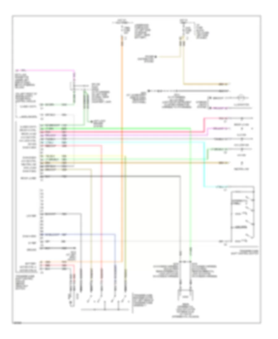 https://portal-diagnostov.com/license.html
Automotive Electricians Portal FZCO
Automotive Electricians Portal FZCO
https://portal-diagnostov.com/license.html
https://portal-diagnostov.com/license.html
Automotive Electricians Portal FZCO
Automotive Electricians Portal FZCOList of elements for Transfer Case Wiring Diagram for Hummer H2 2007:
- (on left front of engine compt) powertrain control module
- 4-hi
- 4-hi ind
- 4-hi ind ctrl
- 4-hi lock
- 4-hi lock ctrl
- 4-hi lock ind
- 4-lo
- 4-lo ind
- 4-lo ind ctrl
- 4wd fuse 15a
- 4wd lo sig
- 4wd low sig
- 5v ref
- Anti-lock brakes system
- Battery
- Chan a enc
- Chan b enc
- Chan c enc
- Chan p enc
- Class 2 data
- Class ii data
- Data link connector (under left side of dash, below steering column)
- Differential lock
- G203 (at lower right side of dash, near right kick panel)
- G310 (at left body mount)
- Ground
- Hi-lo
- Hot at all times
- Hot in run
- I/p fuse block (on lower left side of dash)
- Illumination
- Interior lights system
- Lo-hi
- Low ref
- Motor ctrl a
- Motor ctrl b
- Nca
- Neutral ind
- Pnk
- Power distribution system
- Rear differential lock actuator (on rear axle, at top of differential housing)
- Red
- Rr dif hi ctrl
- Rr dif lk ind
- Rr dif lo ref
- S213 (in i/p harness, 45.4 cm from junction of instrument cluster connector harness to i/p harness)
- S375 (in chassis harness, 63.5 cm from rear differential lock actuator, on chassis harness)
- S376 (in chassis harness, 63.5 cm from rear differential lock actuator, on chassis harness)
- Splice pack sp205 (in i/p harness, on left side of dash, near footwell courtesy lamp)
- Sw sig
- Transfer case encoder motor (at left rear of transfer case assembly)
- Transfer case shift control module (behind headlight switch)
- Transfer case shift control switch
- Trec fuse 30a
- Underhood fuse block (at left side of engine compt, near battery)
TRUNK, TAILGATE, FUEL DOOR
Midgate Wiring Diagram for Hummer H2 2007
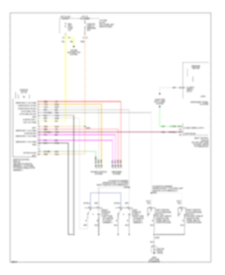 https://portal-diagnostov.com/license.html
Automotive Electricians Portal FZCO
Automotive Electricians Portal FZCO
https://portal-diagnostov.com/license.html
https://portal-diagnostov.com/license.html
Automotive Electricians Portal FZCO
Automotive Electricians Portal FZCOList of elements for Midgate Wiring Diagram for Hummer H2 2007:
- (in midgate harness approximately 13 cm from left midgate latch breakout) s336
- (in midgate harness approximately 47 cm from right midgate latch breakout) s335
- Acc voltage
- Ajar ind sig
- Ajar sw sig 1
- Assembly)
- B12
- Bat
- Body control module (on top left side of dash, above i/p fuse block)
- Class 2 serial data
- Computer data lines system
- Defog sply voltage
- Defogger system
- G c4
- G320 (left side of midgate)
- Gnd
- Hot at all times
- Hot in acc or run
- I/p fuse block (on lower left side of dash)
- Instrument panel cluster
- Latch rel ctrl
- Latch rel sw sig
- Left midgate latch (right side of midgate, at latch assembly)
- Left midgate latch release switch (on left side of midgate trim panel, below midgate glass)
- Logic
- Message center
- Midgate circuit breaker 20a
- Midgate control module (center of midgate assembly, attached to window regulator
- Midgate motor
- Midgate sw dn sig
- Midgate sw up sig
- Motor up sig
- Power distribution system
- Power windows system
- Red
- Right midgate latch (left side of midgate, at latch assembly)
- Right midgate latch release switch (on right side of midgate trim panel, below midgate glass)
- S334
- S339
- Seo accy fuse 10a
- Splice pack sp320
- Tan
WARNING SYSTEMS
Warning Systems Wiring Diagram (1 of 2) for Hummer H2 2007
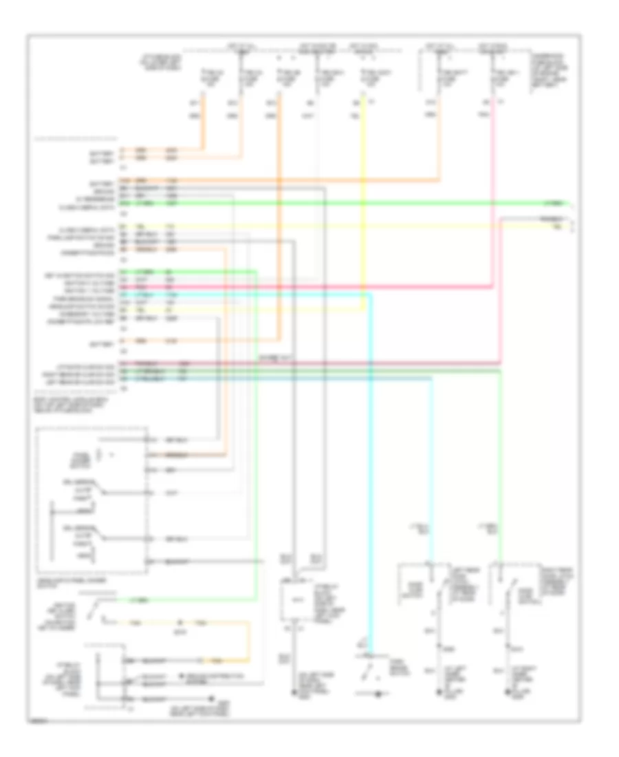 https://portal-diagnostov.com/license.html
Automotive Electricians Portal FZCO
Automotive Electricians Portal FZCO
https://portal-diagnostov.com/license.html
https://portal-diagnostov.com/license.html
Automotive Electricians Portal FZCO
Automotive Electricians Portal FZCOList of elements for Warning Systems Wiring Diagram (1 of 2) for Hummer H2 2007:
- (at left inner center "b" pillar) g302
- (at right inner center "b" pillar) g306
- (on left side of dash, near left kick panel) g200
- 5v reference
- A12
- Accessory voltage
- Auto
- B11
- B12
- Battery
- Body control module (bcm) (on top left side of dash, above i/p fuse block)
- Class 2 serial data
- D12
- Dimmer ptnomtr low ref
- Dimmer ptnomtr sig
- Door ajar switch
- Drl defeat
- E11
- E12
- Except sut
- G200 (on left side of dash, near left kick panel)
- Ground
- Ground distribution system
- Head
- Headlamp & panel dimmer switch
- Headlamp switch on sig
- Hot at all times
- Hot in acc or run
- Hot in acc or run or start
- Hot in run or start
- I/p fuse block (on lower left side of dash)
- I/p relay block (on left side of dash, near left kick panel)
- Ignition 0 voltage
- Ignition 1 voltage
- Ignition key alarm switch (on ignition key cylinder)
- Key in ignition switch sig
- Left rear door latch assembly (at rear of door)
- Left rear dr ajar sw sig
- Liftgate ajar sw sig
- Panel dimmer switch
- Park
- Park brake sw signal
- Park brake switch
- Park lamp switch on sig
- Pnk
- Right rear door latch assembly (at rear of door)
- Right rear dr ajar sw sig
- S219
- S310
- S390
- Tan
- Tbc 2a fuse 15a
- Tbc 2b fuse 15a
- Tbc 2c fuse 15a
- Tbc accy fuse 10a
- Tbc batt fuse 10a
- Tbc ign 0 fuse 10a
- Tbc ign 1 fuse 10a
- Underhood fuse block (at left side of engine compt, near battery)
Warning Systems Wiring Diagram (2 of 2) for Hummer H2 2007
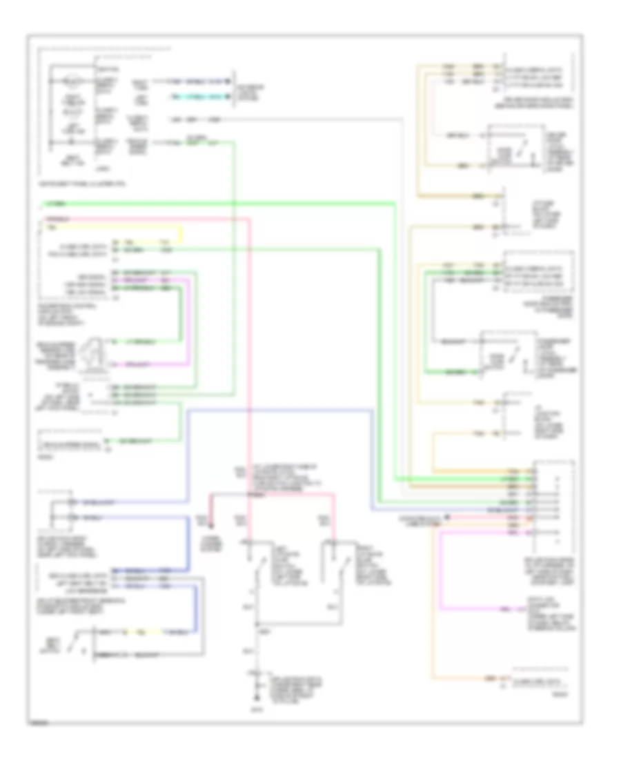 https://portal-diagnostov.com/license.html
Automotive Electricians Portal FZCO
Automotive Electricians Portal FZCO
https://portal-diagnostov.com/license.html
https://portal-diagnostov.com/license.html
Automotive Electricians Portal FZCO
Automotive Electricians Portal FZCOList of elements for Warning Systems Wiring Diagram (2 of 2) for Hummer H2 2007:
- (at lower right side of liftgate, 6.5 cm from right liftgate ajar switch junction to liftgate harness) s902
- A10
- Class 2 serial data
- Class 2 srl data
- Computer data lines system
- Data link connector (dlc) (under left side of dash, below steering column)
- Door ajar switch
- Driver door latch assembly (at rear of driver door)
- Driver door module (ddm) (behind driver's door panel)
- E vehicle speed signal
- Exterior lights system
- G410
- I/p fuse block (on lower left side of dash)
- I/p junction block (on lower right side of dash)
- I/p relay block (on left side of dash, near left kick panel)
- Ignition
- Inflatable restraint sensing & diagnostic module (sdm) (under left front seat)
- Instrument panel cluster (ipc)
- Left liftgate ajar switch (at lower left side of liftgate)
- Left seat belt sw
- Left turn
- Left turn ind
- Logic
- Low reference
- Lt ft dr ajar sw sig
- Lt ft dr sw low ref
- Nca
- Passenger door latch assembly (at rear of passenger door)
- Passenger door module (pdm) (in passenger door)
- Pcm class 2 srl data
- Pnk
- Powertrain control module (pcm) (on left front of engine compt)
- Radio
- Right liftgate ajar switch (at lower right side of liftgate)
- Right turn
- Right turn ind
- Rt ft dr ajar sw sig
- Rt ft dr sw low ref
- S901
- Sdm class 2 srl data
- Seat belt ind
- Seat belt switch
- Splice pack sp205 (in i/p harness, on left side of dash, near footwell courtesy lamp)
- Splice pack sp207 (in body harness, on left side of dash, near left kick panel)
- Splice pack sp410 (inside right rear cargo area, at middle of right "d" pillar)
- Tan
- Vehicle speed sensor (vss) (on rear of transfer case assembly)
- Vehicle speed signal
- Vss high signal
- Vss low signal
- Vss signal
- Wiper/ washer system
WIPER/WASHER
Front Wiper/Washer Wiring Diagram for Hummer H2 2007
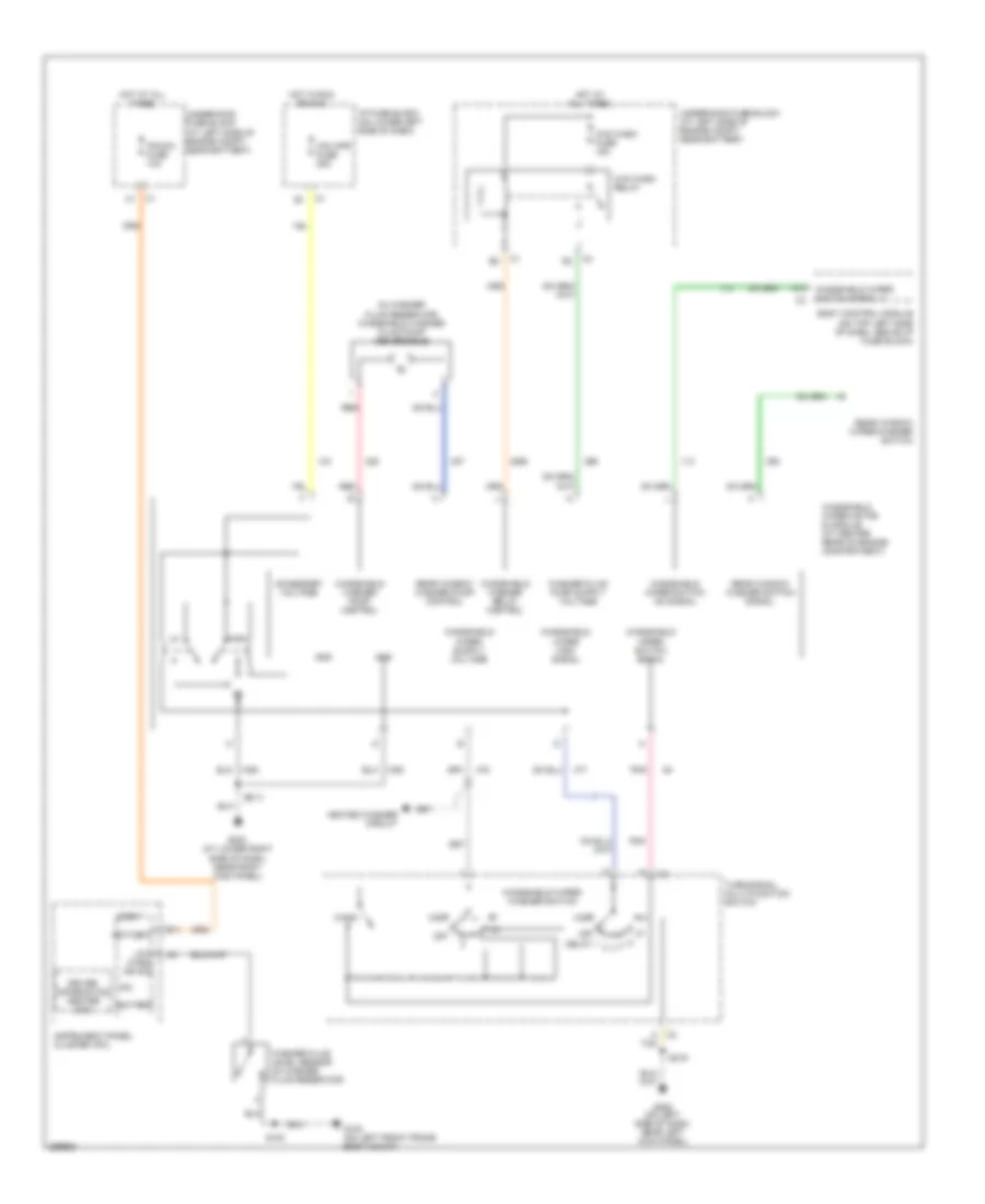 https://portal-diagnostov.com/license.html
Automotive Electricians Portal FZCO
Automotive Electricians Portal FZCO
https://portal-diagnostov.com/license.html
https://portal-diagnostov.com/license.html
Automotive Electricians Portal FZCO
Automotive Electricians Portal FZCOList of elements for Front Wiper/Washer Wiring Diagram for Hummer H2 2007:
- (in washer fluid reservoir) windshield washer fluid pump (reversible)
- A tan
- A10
- Accessory voltage
- B11
- Battery
- Body control module (on top left side of dash, above i/p fuse block)
- Delay 1
- Driver information center (dic)
- G100 (on left front frame body mount)
- G200 (on left side of dash, near left kick panel)
- G203 (at lower right side of dash, near right kick panel)
- Gnd
- Heated washer circuit
- High
- Hot at all times
- Hot in run or acc
- I/p fuse block (on lower left side of dash)
- Instrument panel cluster (ipc)
- Ipc
- Ipc/dic fuse 10a
- Logic
- Low wash ind sig
- Mist
- Off
- Pnk
- Rear window washer pump control
- Rear window washer switch signal
- Rear window wiper/washer switch
- Red
- S100
- S213
- S219
- Turn/signal multi-function switch
- Underhood fuse block (at left side of engine compt, near battery)
- W/s wash fuse 15a
- W/s wash relay
- Wash
- Washer fluid level sensor (in washer fluid reservoir)
- Windshield washer pump control
- Windshield washer relay control
- Windshield wiper high signal
- Windshield wiper motor & module (at center rear of engine compartment)
- Windshield wiper switch on signal
- Windshield wiper switch signal
- Windshield wiper switch signal 2
- Windshield wiper/ washer switch
- Ws wpr fuse 25a
Heated Windshield Washer Wiring Diagram for Hummer H2 2007
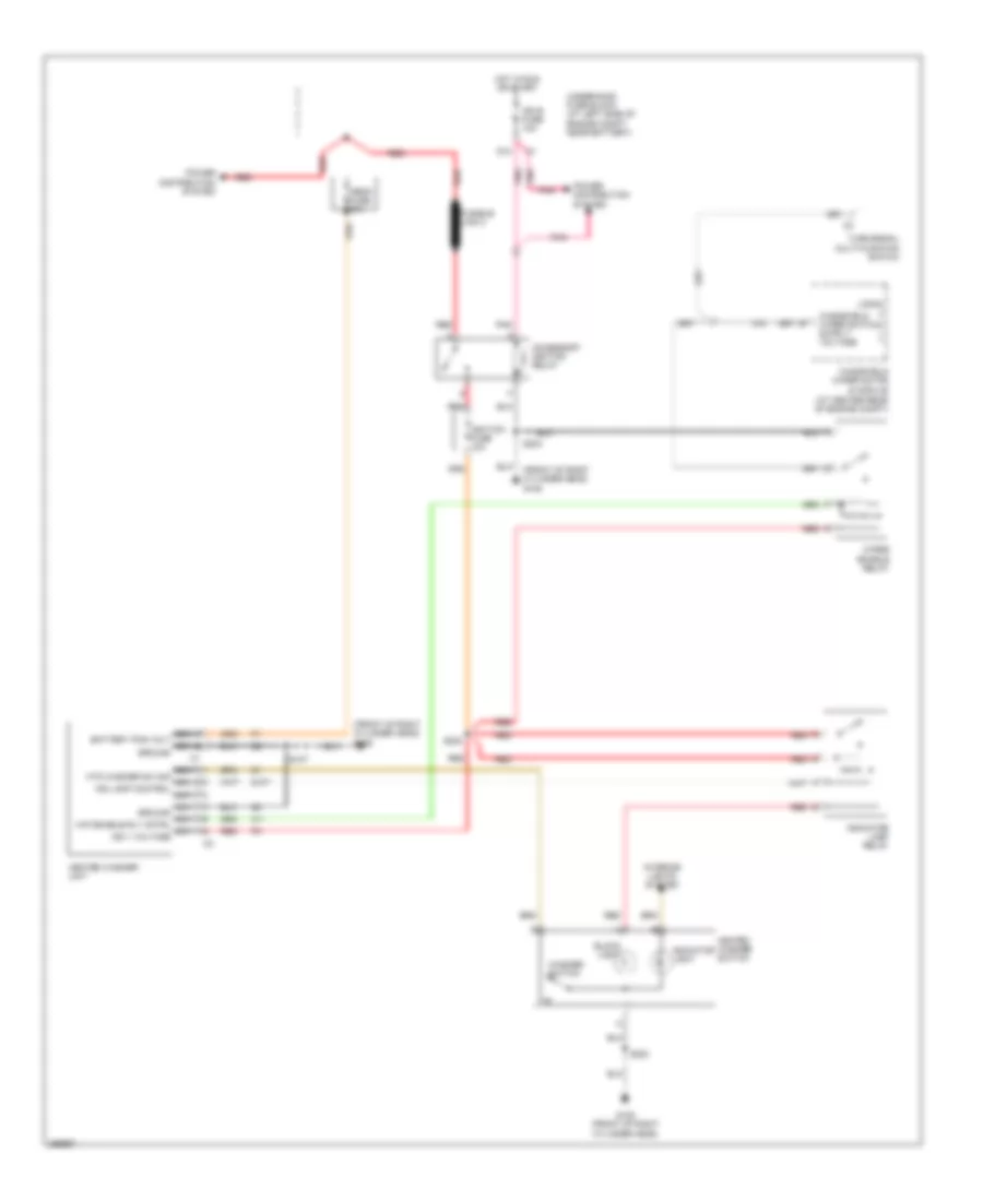 https://portal-diagnostov.com/license.html
Automotive Electricians Portal FZCO
Automotive Electricians Portal FZCO
https://portal-diagnostov.com/license.html
https://portal-diagnostov.com/license.html
Automotive Electricians Portal FZCO
Automotive Electricians Portal FZCOList of elements for Heated Windshield Washer Wiring Diagram for Hummer H2 2007:
- (at center rear of engine compt)
- (front of right cylinder head) g105
- Accessory ignition relay
- Block light
- D10
- Fusible link 2
- G105 (front of right cylinder head)
- Heated washer switch
- Heated washer unit
- Hot in run or start
- Ign e fuse 10a
- Ignition fuse 10a
- Indicator lamp relay
- Indicator light
- Interior lights system
- Logic
- Mega fuse 60a
- Nca battery pos volt nca ground
- Nca ground nca wip enable rly cntrl nca ign 1 voltage
- Nca htd washer sw sig nca ind lamp control nca
- Pnk
- Power distribution system
- Red
- S107
- S202
- S203
- Slp1
- Turn/signal multi-function switch
- Underhood fuse block (at left side of engine compt, near battery)
- Washer switch
- Windshield wiper motor & module
- Wiper enable relay
Rear Wiper/Washer Wiring Diagram for Hummer H2 2007
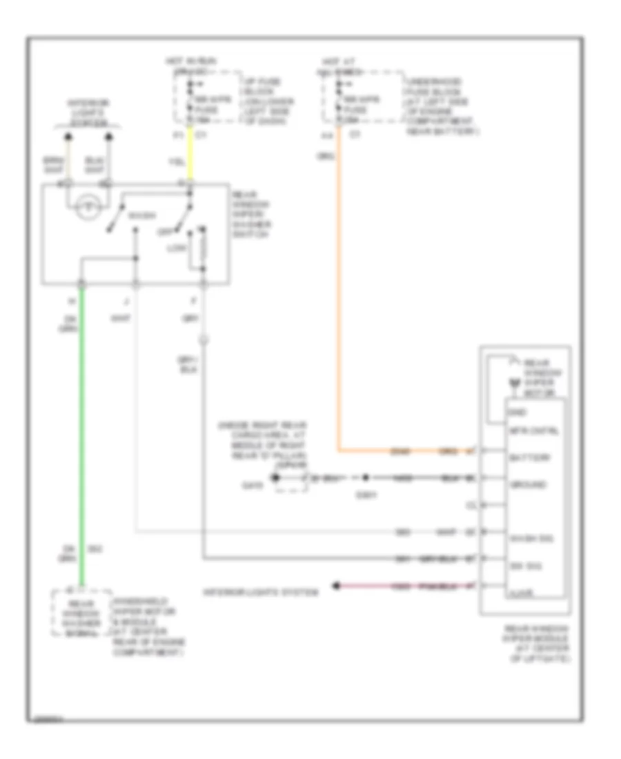 https://portal-diagnostov.com/license.html
Automotive Electricians Portal FZCO
Automotive Electricians Portal FZCO
https://portal-diagnostov.com/license.html
https://portal-diagnostov.com/license.html
Automotive Electricians Portal FZCO
Automotive Electricians Portal FZCOList of elements for Rear Wiper/Washer Wiring Diagram for Hummer H2 2007:
- (inside right rear cargo area, at middle of right rear "d" pillar) sp410
- Ajar
- Battery
- G410
- Gnd
- Ground
- Hot at all times
- Hot in run or acc
- I/p fuse block (on lower left side of dash)
- Interior lights system
- Low
- Mtr cntrl
- Off
- Rear window washer signal
- Rear window wiper module (at center of liftgate)
- Rear window wiper motor
- Rear window wiper/ washer switch
- Rr wpr fuse 15a
- Rr wpr fuse 25a
- S901
- Sw sig
- Underhood fuse block (at left side of engine compartment, near battery)
- Wash
- Wash sig
- Windshield wiper motor & module (at center rear of engine compartment)

 Čeština
 Dansk
Dansk Deutsch
 Ελληνικά
 English
 English
 Español
 Suomi
Suomi Français
 Français
 עברית
עברית Hrvatski
 Magyar
 Italiano
 한국어
한국어 Nederlands
 Polski
 Português
 Português
 Română
 Русский
 Slovenčina
 Slovenščina
 Svenska
 Türkçe
 中文 (中国)
