AIR CONDITIONING
Compressor Wiring Diagram for Pontiac GTO 2005
 https://portal-diagnostov.com/license.html
Automotive Electricians Portal FZCO
Automotive Electricians Portal FZCO
https://portal-diagnostov.com/license.html
https://portal-diagnostov.com/license.html
Automotive Electricians Portal FZCO
Automotive Electricians Portal FZCO
List of elements for Compressor Wiring Diagram for Pontiac GTO 2005:
- A/c
- A/c compressor clutch
- A/c compressor clutch relay (micro)
- A/c ind
- A/c refrigerant pressure sensor (left front corner of engine compt)
- A/c request
- A/c switch
- Behind under hood fuse panel)
- Body control module (bcm) (below right side of dash)
- Clu rly ctrl
- Clutch
- Compressor
- Computer data lines system
- Diode
- Engine sensors fuse 15a
- G105 (rear of engine, near left valve cover, attached to block)
- Heated rear window, hvac & instruments fuse 7.5a
- Hot in run or start
- Hvac control assembly (center of dash, under radio)
- Instrument cluster)
- Instrument panel fuse block (below left end of dash)
- Low ref
- Pnk
- Powertrain control module (pcm) (left side of engine compt)
- Press sens sig
- S111 (top of right strut mount,
- S130 (730mm from engine ground)
- S134 (510 mm from a/c compressor diode)
- Serial data
- Tan
- Uart serial data
- Underhood fuse block (on right side of engine compt)
- Vol
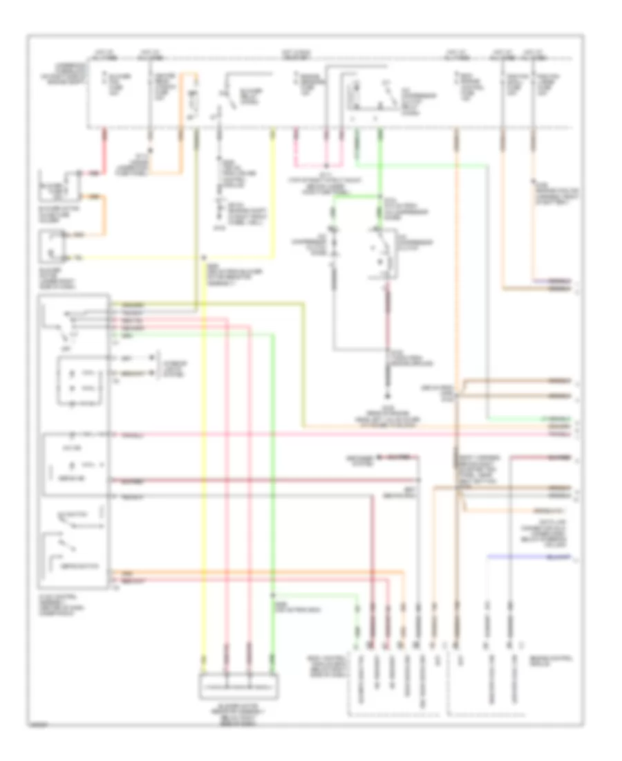
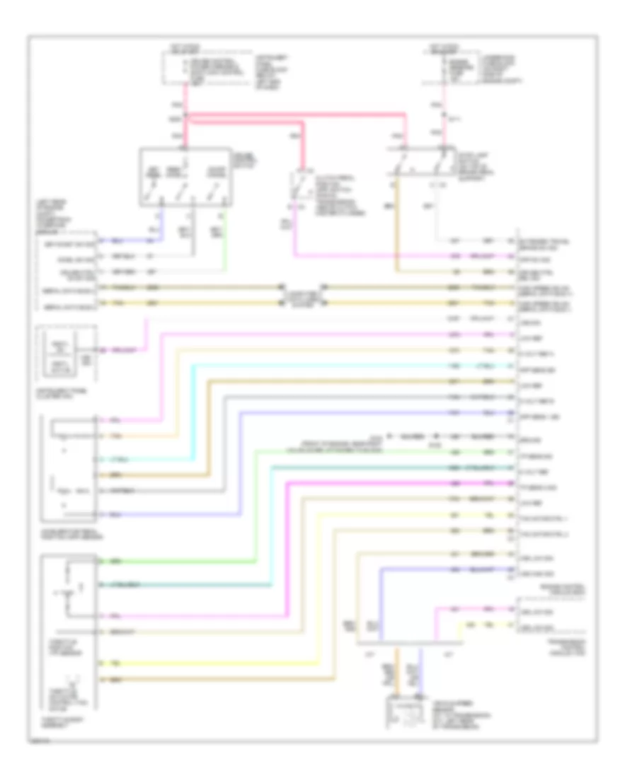
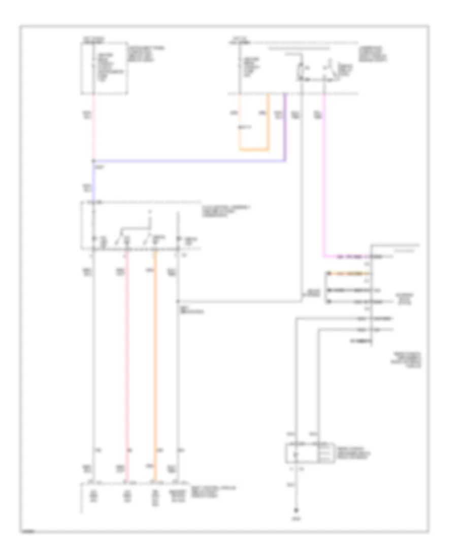
Manual A/C Wiring Diagram (1 of 2) for Pontiac GTO 2005
 https://portal-diagnostov.com/license.html
Automotive Electricians Portal FZCO
Automotive Electricians Portal FZCO
https://portal-diagnostov.com/license.html
https://portal-diagnostov.com/license.html
Automotive Electricians Portal FZCO
Automotive Electricians Portal FZCOList of elements for Manual A/C Wiring Diagram (1 of 2) for Pontiac GTO 2005:
- (295 mm from c206) s105
- A/c compressor clutch
- A/c compressor clutch diode
- A/c compressor clutch relay (micro)
- A/c ind
- A/c request
- A/c switch
- Bat
- Bcm/ engine control fuse 15a
- Blower fan fuse 40a
- Blower fuse 30a
- Blower motor (under right side of dash)
- Blower motor inline fuse holder
- Blower motor resistor assembly (below right side of dash)
- Blower relay (micro)
- Blr mtr low ctrl
- Body control module (bcm) (below right side of dash)
- Data link connector (dlc) (under dash, below steering column)
- Defog ind
- Defog switch
- Defogger system
- Engine control module
- Engine sensors fuse 15a
- G102
- G105 (rear of engine, near left valve cover, attached to block)
- Heated rear window fuse 30a
- High spd cool fan
- Hot at all times
- Hot in run or start
- Hvac control assembly (center of dash, under radio)
- Interior lights system
- Low spd cool fan
- Off
- Panel, near seat bottom) s106
- Pnk
- Rad fan large fuse 30a
- Rad fan small fuse 30a
- Rear defog sw
- Red
- S111 (top of right strut mount, behind under hood fuse panel)
- S114 (inside underhood fuse panel)
- S134 (510 mm from a/c compressor diode)
- S165 (engine cooling harness, front of battery)
- S255 (355 mm from blower motor resistor assembly)
- S256 (335 mm from bcm)
- S257 (behind bcm)
- Sec rear defog sw
- Sp100 (engine compt in right front wheel well)
- Underhood fuse block (on right side of engine compt)
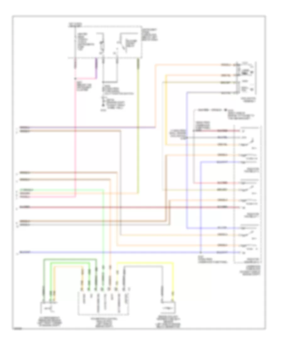
Manual A/C Wiring Diagram (2 of 2) for Pontiac GTO 2005
 https://portal-diagnostov.com/license.html
Automotive Electricians Portal FZCO
Automotive Electricians Portal FZCO
https://portal-diagnostov.com/license.html
https://portal-diagnostov.com/license.html
Automotive Electricians Portal FZCO
Automotive Electricians Portal FZCOList of elements for Manual A/C Wiring Diagram (2 of 2) for Pontiac GTO 2005:
- (1135mm from small engine cooling fan) s156
- (360mm from underhood fuse panel) s239
- 87a
- A/c refrigerant pressure sensor (left front corner of engine compt)
- Batt
- Blower inhibit relay
- Clu rly ctrl
- Cooling fan assembly
- Ect sensor sig
- Engine coolant temperature (ect) sensor (left side of engine, below generator)
- G102
- G103 (right side of engine, attached to the abs bracket)
- Heated rear window, hvac & instruments fuse 7.5a
- Hot in run or start
- Instrument panel fuse block (below left end of dash)
- Large fan
- Low ref
- Powertrain control module (pcm) (left side of engine compt)
- Press sens sig
- Radiator fan relay 1
- Radiator fan relay 2
- Radiator fan relay 3
- S157 (275mm from underhood fuse panel)
- S207 (behind the instrument cluster)
- Small fan
- Sp100 (engine compt in right front wheel well)
- Tan
- Underhood fuse block (on right side of engine compt)
- Vol
ANTI-LOCK BRAKES
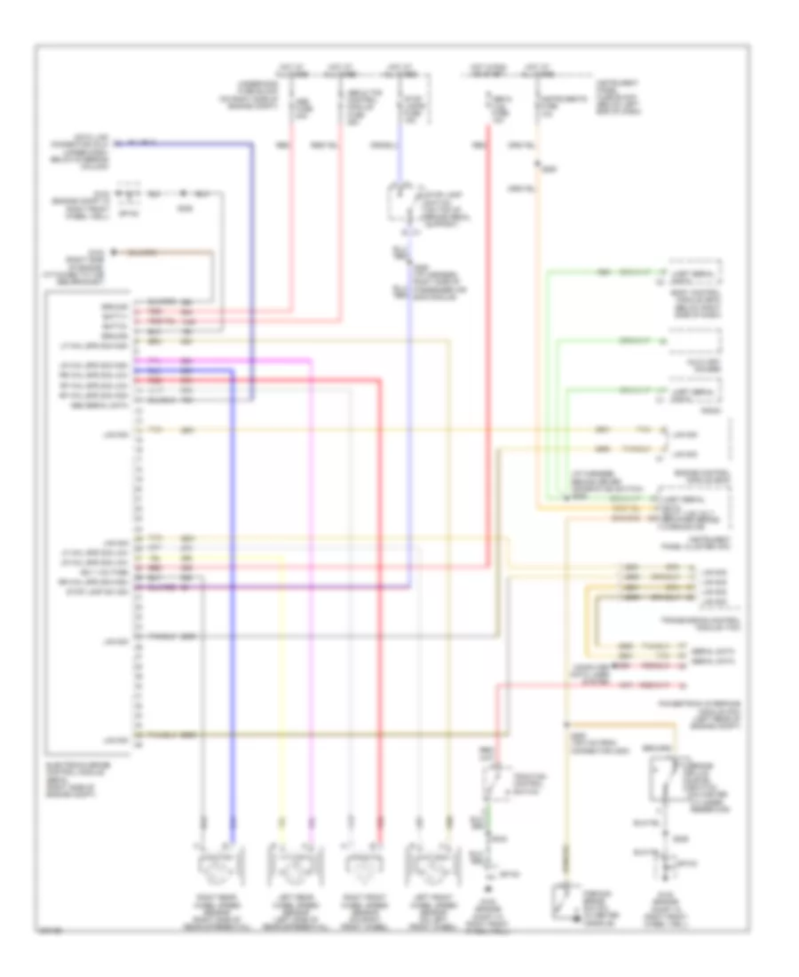
Anti-lock Brakes Wiring Diagram for Pontiac GTO 2005
 https://portal-diagnostov.com/license.html
Automotive Electricians Portal FZCO
Automotive Electricians Portal FZCO
https://portal-diagnostov.com/license.html
https://portal-diagnostov.com/license.html
Automotive Electricians Portal FZCO
Automotive Electricians Portal FZCOList of elements for Anti-lock Brakes Wiring Diagram for Pontiac GTO 2005:
- (i/p harness, behind driver information switch) s253
- Abs & tcs control module fuse 25a
- Abs & tcs fuse 10a
- Abs fuse 40a
- Abs serial data
- Auxiliary gauges
- B c1
- Batt1+
- Batt2+
- Body control module (bcm) (below right side of dash)
- Brake fluid level switch (in master cylinder reservoir)
- C1 a
- Computer data lines system
- Data link connector (dlc) (under dash, below steering column)
- Electronic brake control module (ebcm) (right side of engine compt)
- Engine control module (ecm)
- G102 (engine compt in right front wheel well)
- G103 (right side of engine, attached to the abs bracket)
- Ground
- Hot at all times
- Hot in run or start
- Ign 1 voltage
- Instrument panel cluster (ipc)
- Instrument panel fuse block (below left end of dash)
- Instruments fuse 10a
- Lan sig
- Left front wheel speed sensor (on left front wheel)
- Left rear wheel speed sensor (left side of rear differential)
- Lf whl spd sig high
- Lf whl spd sig low
- Lr whl spd sig high
- Lr whl spd sig low
- Parking brake switch (in center console)
- Powertrain interface module (pim) (left rear of engine compt)
- Radio
- Red
- Rf whl spd sig high
- Rf whl spd sig low
- Right front wheel speed sensor (on right front wheel)
- Right rear wheel speed sensor (right side of rear differential)
- Rr whl spd sig high
- Rr whl spd sig low
- S228
- S229
- S242
- S250 (i/p harness, right side of passenger air bag module)
- S263 (1910 mm from connector c200)
- S293
- Serial data
- Sp100
- Stop lamp sw sig
- Stop lamp switch (on top of brake pedal support)
- Stop lamps fuse 15a
- Tan
- Traction control switch
- Transmission control module (tcm)
- Uart serial data
- Uart serial data batt +ve volt brk/park brake warning ind
- Underhood fuse block (on right side of engine compt)
ANTI-THEFT
Anti-theft Wiring Diagram for Pontiac GTO 2005
 https://portal-diagnostov.com/license.html
Automotive Electricians Portal FZCO
Automotive Electricians Portal FZCO
https://portal-diagnostov.com/license.html
https://portal-diagnostov.com/license.html
Automotive Electricians Portal FZCO
Automotive Electricians Portal FZCOList of elements for Anti-theft Wiring Diagram for Pontiac GTO 2005:
- (above the transmission) g300
- (right rear tail lamp stud) g900
- (right side of passenger seat, under door sill)
- (under carpet, right side of passenger seat) s503
- Acc
- All doors dead lock relay
- All doors lock relay
- Battery voltage
- Bcm/ engine control fuse 15a
- Body control module (below right side of dash)
- Door ajar ind
- Door lock control
- Door lock cylinder switch
- Door lock/ unlock signal
- Door unlock control
- Driver door jamb switch
- Driver door lock actuator
- Driver door lock switch (if equipped)
- Driver door unlock relay
- G102 (engine compartment in right front wheel well)
- G105 (rear of engine, near left valve cover, attached to block)
- G300 (above the transmission)
- Hood ajar switch signal
- Hood theft deterrent switch
- Horn
- Hot at all times
- Ignition key resistor signal
- Ignition switch
- Instrument panel cluster
- Instrument panel fuse block (below left end of dash)
- Interior lights system
- Keyless entry antenna low ref
- Keyless entry antenna signal
- Lock
- Lock signal
- Lt front dr ajar switch signal
- Off
- Passenger door jamb switch
- Passenger door lock actuator
- Passenger door unlock relay
- Power
- Power door locks, theft, horn power windows fuse 15a
- Rear compartment lamp switch
- Rear compt lid ajar switch
- Remote key receiver/ ambient light sensor
- Rt front dr ajar switch signal
- S105
- S106
- S129
- S210
- S221
- S227
- S229
- S235
- S264 (right side of passenger seat, under door sill)
- S300
- S501 (inside driver door)
- S502
- S504 (under carpet, right side of passenger seat)
- S915
- Security ind
- Sp100
- Start
- Tamper switch signal
- Theft horn relay
- Twilight sentinel enable
- Underhood fuse block (on right side of engine compartment)
- Unlock
- Unlock signal
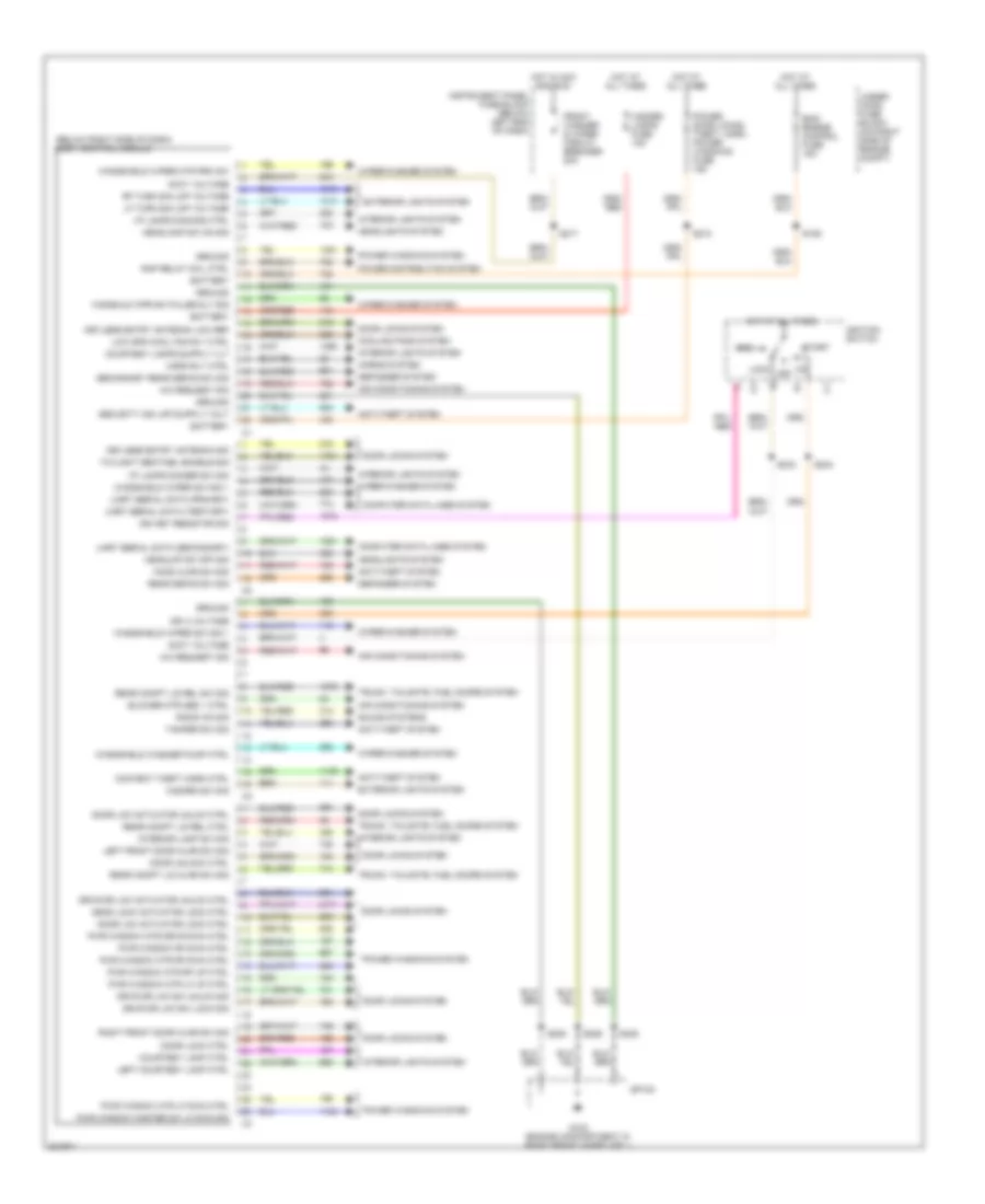
BODY CONTROL MODULES
Body Control Modules Wiring Diagram for Pontiac GTO 2005
 https://portal-diagnostov.com/license.html
Automotive Electricians Portal FZCO
Automotive Electricians Portal FZCO
https://portal-diagnostov.com/license.html
https://portal-diagnostov.com/license.html
Automotive Electricians Portal FZCO
Automotive Electricians Portal FZCOList of elements for Body Control Modules Wiring Diagram for Pontiac GTO 2005:
- (below right side of dash) body control module
- A/c request sig
- Acc
- Accy voltage
- Air conditioning system
- Anti-theft system
- Battery
- Bcm/ engine control fuse 15a
- Blower mtr med 1 ctrl
- Computer data lines system
- Content theft horn ctrl
- Cooling fans system
- Courtesy lamp ctrl
- Dead lock actuator lock ctrl
- Defogger system
- Door lck actuator lock ctrl
- Door lck actuator unlck ctrl
- Door lock ctrl
- Door locks system
- Door unlock ctrl
- Drvr dr lck actuator unlck ctrl
- Drvr dr lck sw lock sig
- Drvr dr lck sw unlck sig
- Exterior lights system
- Front washer & wiper circuit breaker 20a
- G102 (engine compartment in right front wheelwell)
- Ground
- Hazard lamps fuse 15a
- Hazard sw sig
- Headlamp sw on sig
- Headlights system
- Headlmp sw off sig
- Hood ajar sw sig
- Horn rly ctrl
- Horns system
- Hot at all times
- Hot in acc and run
- I/p lamps dimmer sw sig
- I/p lamps dimming ctrl
- Ign 3 voltage
- Ign key resistor sig
- Ignition switch
- Instrument panel fuse block (below left end of dash)
- Interior lamp sw sig
- Interior lights system
- Keyless entry antenna low ref
- Keyless entry antenna sig
- Left courtesy lamp ctrl
- Left front door ajar sw sig
- Lf turn sig lmp voltage
- Lock
- Low spd cool fan rly ctrl
- Off
- Power distribution system
- Power door locks, theft, horn, power windows fuse 15a
- Power windows system
- Pwr window master sw lf dwn sig
- Pwr window mtr drvr dwn ctrl
- Pwr window mtr lf dwn ctrl
- Pwr window mtr lf up ctrl
- Pwr window mtr rf dwn ctrl
- Pwr window mtr rf up ctrl
- Pwr window rf dwn ctrl
- Radio on sig
- Rap relay coil ctrl
- Rear compt lid ajar sw sig
- Rear compt lid rel ctrl
- Rear compt lid rel sw sig
- Rear defog sw sig
- Rf turn sig lmp voltage
- Right front door ajar sw sig
- S106
- S210
- S217
- S229
- S235
- S243
- S244
- Secondary rear defog sw sig
- Sound systems
- Sp100
- Start
- Tamper sw sig
- Trunk, tailgate, fuel doors system
- Twilight sentinel enable sig
- Uart serial data (primary)
- Uart serial data (secondary)
- Uart serial data (tertiary)
- Under- hood fuse block (on right side of engine compt)
- Windshield washer pump ctrl
- Windshield wiper mtr prk sw
- Windshield wiper sw sig 1
- Wiper/washer system
- Wndshld wpr sw pulse dly sig
COMPUTER DATA LINES
Computer Data Lines Wiring Diagram for Pontiac GTO 2005
 https://portal-diagnostov.com/license.html
Automotive Electricians Portal FZCO
Automotive Electricians Portal FZCO
https://portal-diagnostov.com/license.html
https://portal-diagnostov.com/license.html
Automotive Electricians Portal FZCO
Automotive Electricians Portal FZCOList of elements for Computer Data Lines Wiring Diagram for Pontiac GTO 2005:
- (i/p harness, behind driver information switch) s253
- Acc
- Auxiliary gauges
- Bcm/engine control fuse 15a
- Body control module (bcm) (below right side of dash)
- Class 2 serial data
- Cruise control switch
- Cruise on sig
- Cruise res/accel sig
- Cruise set/coast sig
- Data link connector (under dash, below steering column)
- Electronic brake control module (ebcm) (right side of engine compt)
- Engine control module (ecm)
- G102 (engine compt
- G102 (engine compt in right front wheel well)
- Hot at all times
- Ignition switch
- In right front wheel well)
- Inflatable restraint sensing & diagnostic module (sdm) (below center console)
- Instrument panel cluster (ipc)
- Lock
- Off
- Powertrain interface module (pim) (behind left rear quarter window)
- Primary uart data
- Radio
- Run
- S105
- S106
- S228
- S236
- S240
- S244
- S249 (behind driver information switch)
- Secondary uart data
- Serial data bus +
- Serial data bus -
- Splice pack sp100
- Start
- Switch sig
- Tan
- Tertiary uart data
- Traction control switch
- Transmission control module (tcm)
- Uart serial data
- Underhood fuse block (on right side of engine compt)
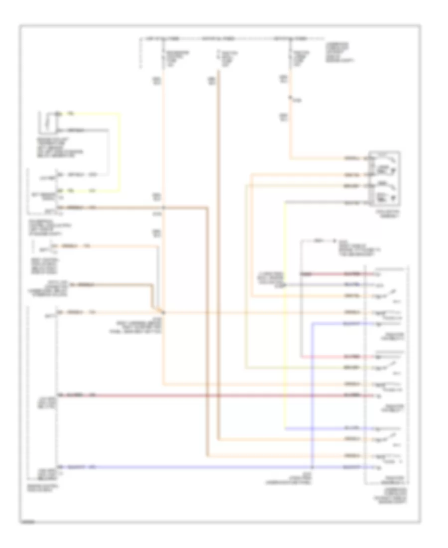
COOLING FAN
Cooling Fan Wiring Diagram for Pontiac GTO 2005
 https://portal-diagnostov.com/license.html
Automotive Electricians Portal FZCO
Automotive Electricians Portal FZCO
https://portal-diagnostov.com/license.html
https://portal-diagnostov.com/license.html
Automotive Electricians Portal FZCO
Automotive Electricians Portal FZCOList of elements for Cooling Fan Wiring Diagram for Pontiac GTO 2005:
- (1135mm from small engine cooling fan) s156
- 87a
- Batt
- Bcm/engine control fuse 15a
- Body control module (bcm) (below right side of dash)
- Cooling fan assembly
- Data link connector (under dash, below steering column)
- Ect sensor signal
- Engine control module (ecm)
- Engine coolant temperature (ect) sensor (on left side of engine, below generator)
- G103 (right side of engine, attached to the abs bracket)
- High spd cool fan rel ctrl
- Hot at all times
- Large fan
- Low ref
- Low spd cool fan rel ctrl
- Powertrain control module (pcm) (left side of of engine compt)
- Rad fan large fuse 30a
- Rad fan small fuse 30a
- Radiator fan relay 1
- Radiator fan relay 2
- Radiator fan relay 3
- S105
- S106 (body harness, behind right quarter trim panel, near seat bottom)
- S157 (275mm from underhood fuse panel)
- S165
- S239
- Small fan
- Underhood fuse block (on right side of engine compt)
CRUISE CONTROL
Cruise Control Wiring Diagram for Pontiac GTO 2005
 https://portal-diagnostov.com/license.html
Automotive Electricians Portal FZCO
Automotive Electricians Portal FZCO
https://portal-diagnostov.com/license.html
https://portal-diagnostov.com/license.html
Automotive Electricians Portal FZCO
Automotive Electricians Portal FZCOList of elements for Cruise Control Wiring Diagram for Pontiac GTO 2005:
- (left rear of engine compt) powertrain interface module
- 5 volt ref
- 5 volt ref a
- 5 volt ref b
- A/t
- Accel sw sig
- Accelerator pedal position (app) sensor
- App sens 1 sig
- App sens sig
- C3 c
- Clutch pedal position (cpp) switch (manual transmission) (above clutch master cylinder)
- Computer data lines system
- Cpp sw sig
- Crctl active
- Crctl on
- Cruise control switch
- Cruise control, power mirrors & shiftlock control fuse 10a
- Cruise ctrl on sw sig
- Cruise ctrl rel sig
- D c3
- Engine control module (ecm)
- Engine sensors fuse 15a
- Extended travel brake sw sig
- G104 (front of engine, near right valve cover, attached to block)
- Ground
- High speed gmlan serial data bus (+)
- High speed gmlan serial data bus (-)
- Hot in run or start
- Instrument panel cluster (ipc)
- Instrument panel fuse block (below left end of dash)
- Low ref
- M/t
- On/off cancel
- Pnk
- Resm accel
- S111
- S128
- S208
- Serial data bus(+)
- Serial data bus(-)
- Set decel
- Set/coast sw sig
- Stop lamp switch (on top of brake pedal support)
- Tac motor ctrl 1
- Tac motor ctrl 2
- Tan
- Throttle actuator control (tac) motor
- Throttle body assembly
- Throttle position (tp) sensor
- Tp sens 2 sig
- Tp sens sig
- Transmission control module (tcm)
- Underhood fuse block (on right side of engine compt)
- Vehicle speed sensor (a/t: in transmission) (m/t: left rear of transmission)
- Vss high sig
- Vss low sig
- Vss sig
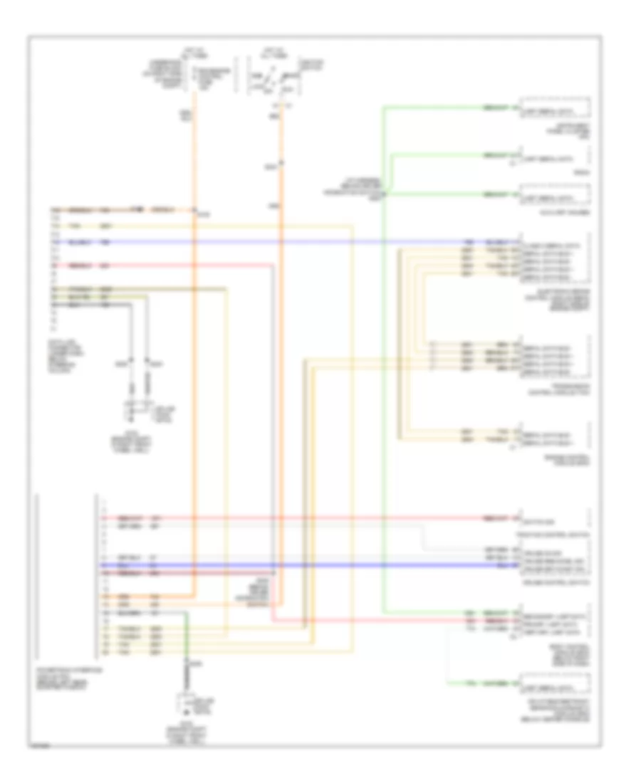
DEFOGGERS
Defoggers Wiring Diagram for Pontiac GTO 2005
 https://portal-diagnostov.com/license.html
Automotive Electricians Portal FZCO
Automotive Electricians Portal FZCO
https://portal-diagnostov.com/license.html
https://portal-diagnostov.com/license.html
Automotive Electricians Portal FZCO
Automotive Electricians Portal FZCOList of elements for Defoggers Wiring Diagram for Pontiac GTO 2005:
- A/c led ind
- A/c req sig
- A/c sw
- Ant dfg
- Antenna solid state
- Body control module (below right side of dash)
- Defog led
- Defog relay (mini)
- Defog sw
- Dfg
- G400
- Gnd
- Heated rear window fuse 30a
- Heated rear window, hvac & instruments fuse 7.5a
- Hot at all times
- Hot in run or start
- Hvac control assembly (center of dash, under radio)
- Instrument panel fuse block (below left end of dash)
- Nca
- Rear window defogger & radio antenna module
- Rear window defogger grid & radio antenna
- Rr dfg sw sig
- S114
- S207
- S257 (behind bcm)
- Secndry rr dfg sw sig
- Sig
- Sound systems
- Underhood fuse block (right side of engine compt)
ENGINE PERFORMANCE
6.0L VIN U
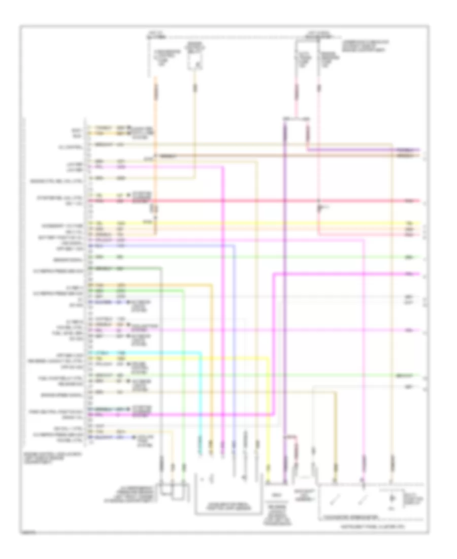
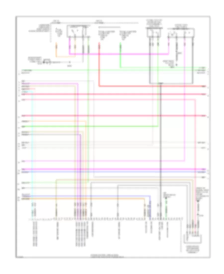
6.0L VIN U, Engine Performance Wiring Diagram (1 of 6) for Pontiac GTO 2005
 https://portal-diagnostov.com/license.html
Automotive Electricians Portal FZCO
Automotive Electricians Portal FZCO
https://portal-diagnostov.com/license.html
https://portal-diagnostov.com/license.html
Automotive Electricians Portal FZCO
Automotive Electricians Portal FZCOList of elements for 6.0L VIN U, Engine Performance Wiring Diagram (1 of 6) for Pontiac GTO 2005:
- 5v ref a
- 5v ref b
- A/c refrig press sen sig
- A/c refrigerant pressure sensor (left front corner of engine compartment)
- A/t
- Accelerator pedal position (app) sensor
- Accessory voltage
- App sen 1 sig
- App sen 2 sig
- Auto trans fuse 15a
- Battery positive vol
- Bcm/engine control fuse 15a
- Bus +
- Bus -
- Computer data lines system
- Cooling fans system
- Cpp sw sig
- Crank vol
- Cruise control system
- Engine control module (ecm) (left side of engine compartment)
- Engine controls relay
- Engine ctrl rel coil ctrl
- Engine sensors fuse 15a
- Engine speed signal
- Exterior lights system
- Fan rel ctrl
- Fuel level sen
- Fuel pump relay ctrl
- Hot at all times
- Hot in run run or start
- Ign 1 vol
- Ign 3 vol
- Ign coil 1 ctrl
- Instrument panel cluster (ipc)
- Low ref
- M/t
- Mil
- Mil control
- Multi- function display
- Park neutral position sw
- Pnk
- Pnk s111
- Release sig
- Reverse lockout sol ctrl
- Reverse lockout solenoid (top left on transmission)
- S105
- S106
- S110
- Sensor signal
- Skip shift coil assembly
- Speedometer
- Starter rel coil ctrl
- Starting/ charging system
- Sw sig
- Tachometer
- Tan
- Underhood fuse block (on right side of engine compartment)
- Vss signal
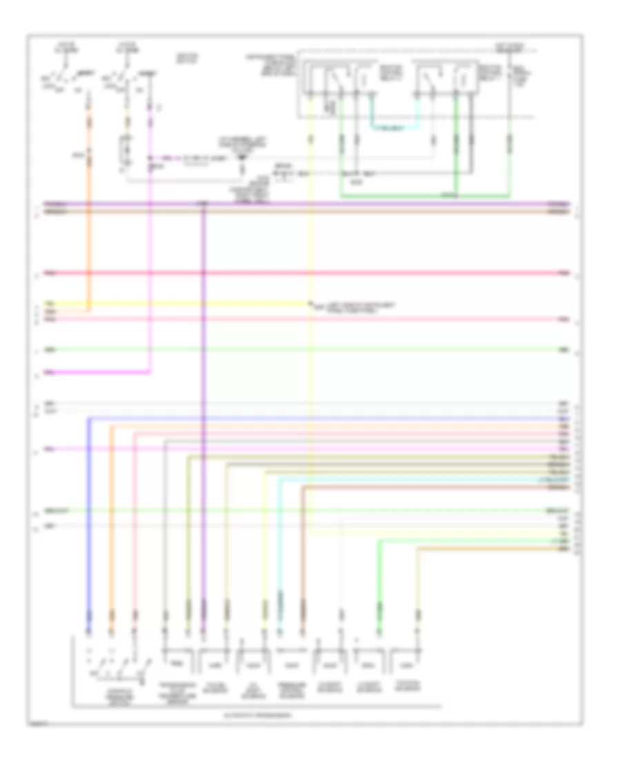
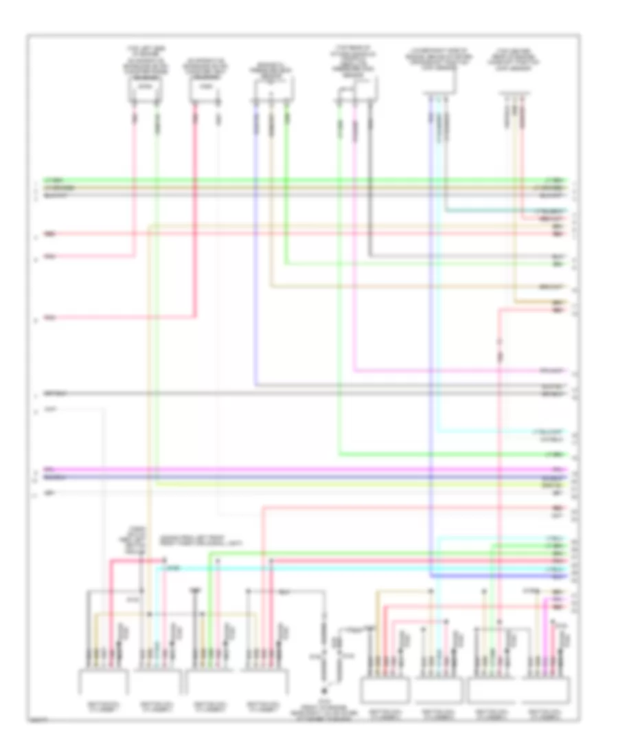
6.0L VIN U, Engine Performance Wiring Diagram (2 of 6) for Pontiac GTO 2005
 https://portal-diagnostov.com/license.html
Automotive Electricians Portal FZCO
Automotive Electricians Portal FZCO
https://portal-diagnostov.com/license.html
https://portal-diagnostov.com/license.html
Automotive Electricians Portal FZCO
Automotive Electricians Portal FZCOList of elements for 6.0L VIN U, Engine Performance Wiring Diagram (2 of 6) for Pontiac GTO 2005:
- (i/p harness, left side of steering column) s290
- (left side of instrument panel fuse panel)
- (not
- 1-2 shift solenoid
- 2-3 shift solenoid
- 3-2 shift solenoid
- Acc
- Automatic transmission
- Ecm signal fuse 7.5a
- Ecm/tcm control relay 1
- Ecm/tcm control relay 2
- G102 (engine compartment, right front wheel well)
- Hot at all times
- Hot in run or start
- Ignition switch
- Instrument panel fuse block (below left end of dash)
- Lock
- Manifold pressure switch
- Off
- Pnk
- Pressure control solenoid
- S109
- S238
- S289
- S291
- Sp100
- Start
- Tan
- Tcc en solenoid
- Tcc pwm solenoid
- Transmission fluid temperature sensor
- Used)
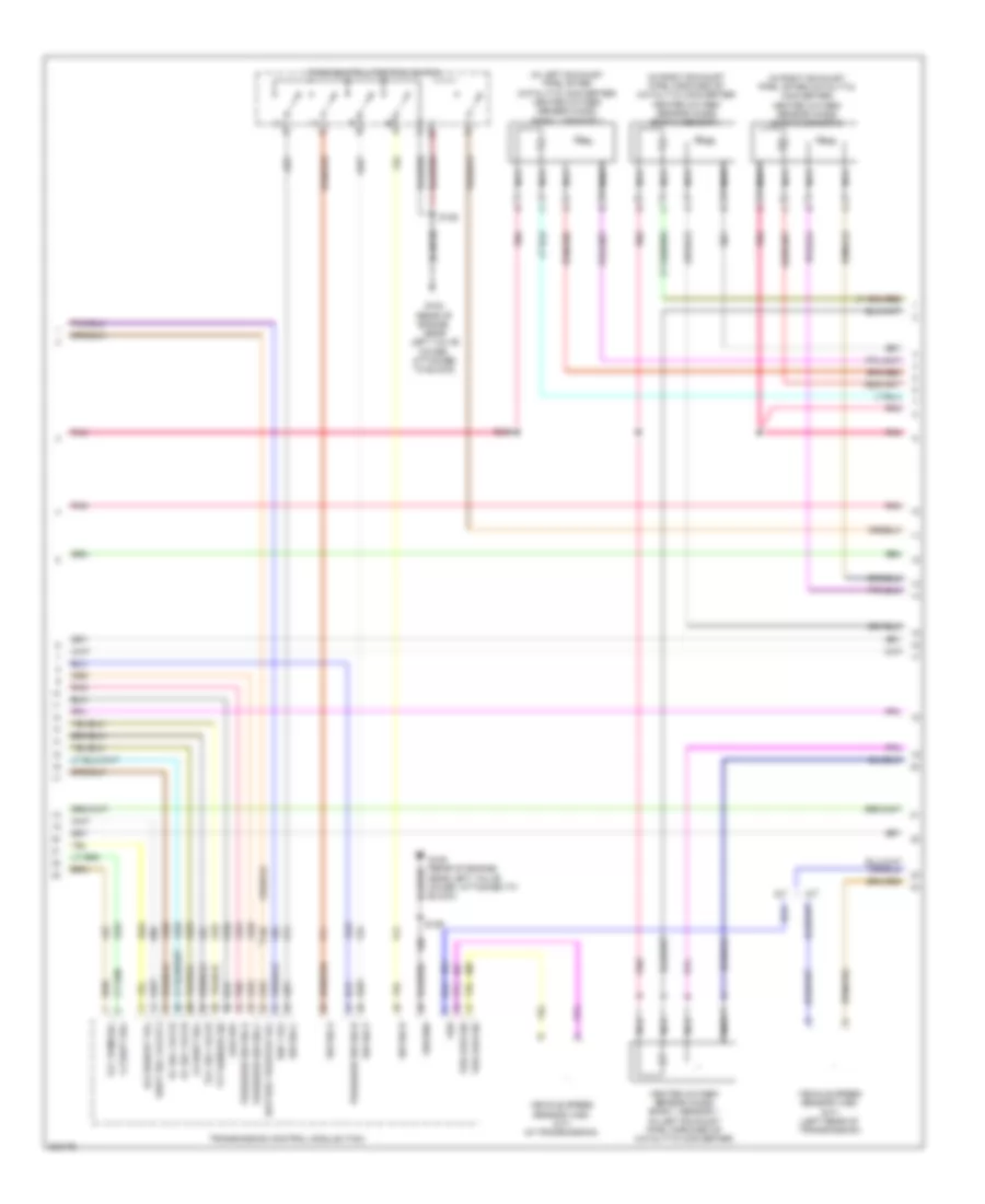
6.0L VIN U, Engine Performance Wiring Diagram (3 of 6) for Pontiac GTO 2005
 https://portal-diagnostov.com/license.html
Automotive Electricians Portal FZCO
Automotive Electricians Portal FZCO
https://portal-diagnostov.com/license.html
https://portal-diagnostov.com/license.html
Automotive Electricians Portal FZCO
Automotive Electricians Portal FZCOList of elements for 6.0L VIN U, Engine Performance Wiring Diagram (3 of 6) for Pontiac GTO 2005:
- (in left exhaust pipe, after catalytic converter) heated oxygen sensor (ho2s) bank 1 sensor 2
- (in right exhaust pipe, after catalytic converter) heated oxygen sensor (ho2s) bank 2 sensor 2
- (in right exhaust pipe, forward of catalytic converter) heated oxygen sensor (ho2s) bank 2 sensor 1
- 1-2 shift sol
- 2-3 shift sol
- A/t
- Accessory vol
- Battery positive vol
- G104 (rear of engine, near left valve cover, attached to block)
- G105 (rear of engine, near left valve cover, attached to block)
- Ground
- Heated oxygen sensor (ho2s) bank 1 sensor 1 (in left exhaust pipe, forward of catalytic converter)
- Ign 1 vol
- Low ref
- M/t
- Nca
- Park/neutral position switch
- Pc sol valve
- Pnk
- Pressure sw sig a
- Pressure sw sig b
- Pressure sw sig c
- S129
- S246
- Shift sol valve 3
- Sw sig a
- Sw sig b
- Sw sig c
- Sw sig p
- Tcc pwm sol
- Tcc sol valve
- Tft sensor sig
- Transmission control module (tcm)
- Vehicle speed sensor (vss) (a/t) (in transmission)
- Vehicle speed sensor (vss) (m/t) (left rear of transmission)
- Vss
- Vss low sig
6.0L VIN U, Engine Performance Wiring Diagram (4 of 6) for Pontiac GTO 2005
 https://portal-diagnostov.com/license.html
Automotive Electricians Portal FZCO
Automotive Electricians Portal FZCO
https://portal-diagnostov.com/license.html
https://portal-diagnostov.com/license.html
Automotive Electricians Portal FZCO
Automotive Electricians Portal FZCOList of elements for 6.0L VIN U, Engine Performance Wiring Diagram (4 of 6) for Pontiac GTO 2005:
- (engine compt in right front wheel well) g102
- (front of engine, near right valve cover, attached to block) g104
- (in fuel tank) fuel pump & sender assembly
- (in fuel tank, on cover of fuel pump assembly) fuel tank pressure sensor
- (or 381)
- (right rear tail lamp stud) g900
- Air conditioning system
- Clutch rel ctrl
- Engine control module (ecm) (left side of engine compartment)
- Fuel injectors & ignition module fuse 15a
- Fuel pump fuse 15a
- Fuel pump relay
- Ho2s bank 1 sen 2 heater
- Ho2s bank 2 sen 2 heater
- Ho2s high sig bank 1 sen 2
- Ho2s high sig bank 2 sen 2
- Ho2s low sig bank 1 sen 2
- Ho2s low sig bank 2 sen 2
- Hot at all times
- Iat sensor signal
- Low ref
- Low reference
- Maf sensor signal
- Mass airflow (maf) sensor (on air intake assembly)
- Park/neutral sig
- Pnk
- Red
- S129
- S158
- S232
- Skip shift sol ctrl
- Sp100
- Underhood fuse block (right side of engine compartment)
- Vss high sig
- Vss low sig
6.0L VIN U, Engine Performance Wiring Diagram (5 of 6) for Pontiac GTO 2005
 https://portal-diagnostov.com/license.html
Automotive Electricians Portal FZCO
Automotive Electricians Portal FZCO
https://portal-diagnostov.com/license.html
https://portal-diagnostov.com/license.html
Automotive Electricians Portal FZCO
Automotive Electricians Portal FZCOList of elements for 6.0L VIN U, Engine Performance Wiring Diagram (5 of 6) for Pontiac GTO 2005:
- (2240mm from left front front park/turn signal light)
- (725mm (28.5 in) from left ignition module)
- (lower right side of engine, behind starter) crankshaft position (ckp) sensor
- (top center rear of engine) camshaft position (cmp) sensor
- (top left side of engine)
- (top rear of
- Engine oil pressure (eop) sensor
- Evaporative emissions (evap) canister purge solenoid
- Evaporative emissions (evap) canister vent solenoid
- G104 (front of engine, near right valve cover, attached to block)
- Ignition coil cylinder 1
- Ignition coil cylinder 2
- Ignition coil cylinder 3
- Ignition coil cylinder 4
- Ignition coil cylinder 5
- Ignition coil cylinder 6
- Ignition coil cylinder 7
- Ignition coil cylinder 8
- Intake manifold) manifold absolute pressure (map) sensor
- Nca
- Plug spark
- Pnk
- Red
- S128
- S130
- S132
- S133
- S154
- S155
- S159
- S160
- Spark plug
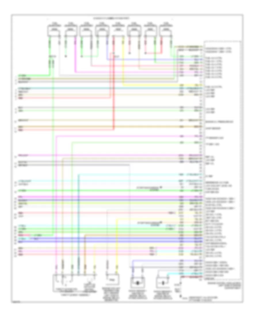
6.0L VIN U, Engine Performance Wiring Diagram (6 of 6) for Pontiac GTO 2005
 https://portal-diagnostov.com/license.html
Automotive Electricians Portal FZCO
Automotive Electricians Portal FZCO
https://portal-diagnostov.com/license.html
https://portal-diagnostov.com/license.html
Automotive Electricians Portal FZCO
Automotive Electricians Portal FZCOList of elements for 6.0L VIN U, Engine Performance Wiring Diagram (6 of 6) for Pontiac GTO 2005:
- (in each cylinders intake port)
- (near right valve cover, attached to block)
- 5v ref
- Camp sensor
- Ckp sensor signal
- Duty cycle sig
- Ect sen sig
- Engine control module (ecm) (left side of engine compartment)
- Engine coolant temperature (ect) sensor (left side of engine, below generator)
- Engine oil pressure sig
- Evap sol ctrl
- Fuel inj 1 ctrl
- Fuel inj 2 ctrl
- Fuel inj 3 ctrl
- Fuel inj 4 ctrl
- Fuel inj 5 ctrl
- Fuel inj 6 ctrl
- Fuel inj 7 ctrl
- Fuel inj 8 ctrl
- Fuel injector 1
- Fuel injector 2
- Fuel injector 3
- Fuel injector 4
- Fuel injector 5
- Fuel injector 6
- Fuel injector 7
- Fuel injector 8
- G104
- Ground
- Ho2s bank 1 sen 1 ctrl
- Ho2s bank 2 sen 1 ctrl
- Ho2s high sig bank 1 sen 1
- Ho2s high sig bank 2 sen 1
- Ho2s low sig bank 1 sen 1
- Ho2s low sig bank 2 sen 1
- Ign coil 2 ctrl
- Ign coil 3 ctrl
- Ign coil 4 ctrl
- Ign coil 5 ctrl
- Ign coil 6 ctrl
- Ign coil 7 ctrl
- Ign coil 8 ctrl
- Knock sen 1 return
- Knock sen 1 signal
- Knock sen 2 return
- Knock sen 2 sig
- Knock sensor 1 (center of engine, below intake manifold)
- Knock sensor 2 (center of engine, below intake manifold)
- Low coolant level ind
- Low ref
- Map sen sig
- Red
- Ref vol
- Reference voltage
- S128
- S137
- S138
- Starting/charging system
- Tac motor ctrl-1
- Tac motor ctrl-2
- Throttle actuator control (tac) motor
- Throttle body assembly
- Throttle position (tp) sensor
- Tp sen 1 sig
- Tp sensor 2 sig
- Turn on sig
- Vent sol ctrl
EXTERIOR LIGHTS
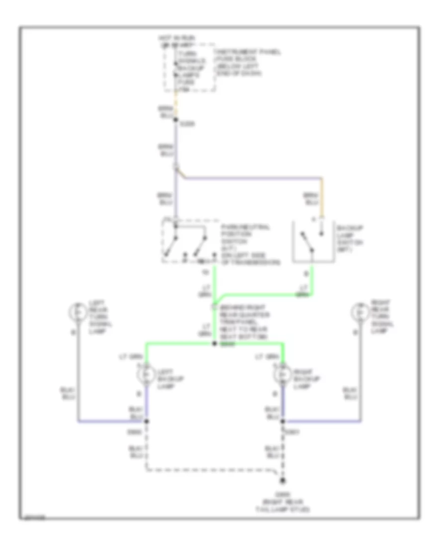
Back-up Lamps Wiring Diagram for Pontiac GTO 2005
 https://portal-diagnostov.com/license.html
Automotive Electricians Portal FZCO
Automotive Electricians Portal FZCO
https://portal-diagnostov.com/license.html
https://portal-diagnostov.com/license.html
Automotive Electricians Portal FZCO
Automotive Electricians Portal FZCOList of elements for Back-up Lamps Wiring Diagram for Pontiac GTO 2005:
- (behind right rear quarter trim panel, next to rear seat bottom) s905
- Backup lamp switch (m/t)
- G900 (right rear tail lamp stud)
- Hot in run or start
- Instrument panel fuse block (below left end of dash)
- Left backup lamp
- Left rear turn signal lamp
- Park/neutral position switch (a/t) (on left side of transmission)
- Rev
- Right backup lamp
- Right rear turn signal lamp
- S206
- S900
- S901
- Turn signals, backup lamps fuse 15a
Exterior Lamps Wiring Diagram (1 of 2) for Pontiac GTO 2005
 https://portal-diagnostov.com/license.html
Automotive Electricians Portal FZCO
Automotive Electricians Portal FZCO
https://portal-diagnostov.com/license.html
https://portal-diagnostov.com/license.html
Automotive Electricians Portal FZCO
Automotive Electricians Portal FZCOList of elements for Exterior Lamps Wiring Diagram (1 of 2) for Pontiac GTO 2005:
- (1900 mm from left marker light) s153
- (engine compt in right front wheel well)
- 5-100ma
- Auto
- Back-up lamps circuit
- Backup lamps circuit
- Body control module (below right side of dash)
- Flasher relay
- G102
- G102 (engine compt in right front wheel well)
- G900 (right rear tail lamp stud)
- Hazard switch
- Hdlmps off
- Hdlmps on
- Hdlp ret
- Head
- Headlamp switch
- Headlights system
- Hot at all times
- Hot in run or acc
- Hzrd sw sig
- Instrument panel fuse block (below left end of dash)
- Interior lights system
- Left front marker lamp
- Left front park/turn signal lamp
- Left rear turn signal lamp
- Off
- Park
- Park lamp
- Park lamps fuse 10a
- Park lamps relay
- Prk lp ret
- Right front marker lamp
- Right front park/turn signal lamp
- Right rear turn signal lamp
- S131
- S161
- S162
- S206
- S215
- S231
- S900
- S901
- S903 (front of under hood fuse panel)
- Sense
- Sp100
- Turn lamp
- Turn signals, backup lamps fuse 15a
Exterior Lamps Wiring Diagram (2 of 2) for Pontiac GTO 2005
 https://portal-diagnostov.com/license.html
Automotive Electricians Portal FZCO
Automotive Electricians Portal FZCO
https://portal-diagnostov.com/license.html
https://portal-diagnostov.com/license.html
Automotive Electricians Portal FZCO
Automotive Electricians Portal FZCOList of elements for Exterior Lamps Wiring Diagram (2 of 2) for Pontiac GTO 2005:
- (315 mm (12.4 in) from bcm) s276
- (behind bcm) s275
- (behind right kick panel, near passenger door pass through) s317
- (cut wire)
- (left of instrument panel fuse panel) s307
- Body control module (below right side of dash)
- C1 c1
- Center high mounted stop lamp
- Center high mounted stop lamp (spoiler)
- Cover is closed
- Cruise control system
- G900 (right rear tail lamp stud)
- Gnd
- Gnd1
- Gnd2
- Hazard lamps fuse 15a
- Hazard/ theft indicator relay
- Hot at all times
- Instrument panel cluster
- Instrument panel fuse block (below left end of dash)
- Left tail/ stop lamp
- Left turn ind
- License lamps
- Lt sig
- Nca
- Park lamp
- Pk lp
- Pwr
- Red
- Right tail/ stop lamp
- Right turn ind
- Rt sig
- S163
- S250 (i/p harness, right side of passenger air bag module)
- S906
- S907
- S908
- S909
- S910
- S911
- S920
- S921
- Stop lamp
- Stop lamp switch (on top of brake pedal support)
- Stop lamps fuse 15a
- Stp
- Switch closed when dust b
- Trailer a
- Trailer harness connector
- Trailer harness connector a
- Trailer harness connector b
- Trlr brk
- Turn signal multifunction switch
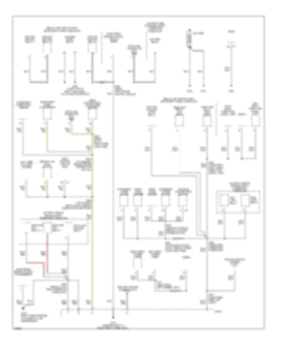
GROUND DISTRIBUTION
Ground Distribution Wiring Diagram (1 of 3) for Pontiac GTO 2005
 https://portal-diagnostov.com/license.html
Automotive Electricians Portal FZCO
Automotive Electricians Portal FZCO
https://portal-diagnostov.com/license.html
https://portal-diagnostov.com/license.html
Automotive Electricians Portal FZCO
Automotive Electricians Portal FZCOList of elements for Ground Distribution Wiring Diagram (1 of 3) for Pontiac GTO 2005:
- (below left end of dash) instrument panel fuse block
- (not used) auxiliary gauges
- (on right side of engine compt) underhood fuse block
- Accessory power outlet
- Battery
- Blower inhibit relay
- Blower relay
- Body control module (bcm)
- Brake fluid level switch
- Console compartment switch
- Data link connector (dlc) obd2
- Daytime running lamps relay
- Ecm/tcm control relay 1
- Ecm/tcm control relay 2
- Electronic brake control module (ebcm)
- Fog lamp relay
- From splice s128 (diagram 2 of 3)
- From splice s235 (diagram 2 of 3)
- Front cigar lighter
- Fuel pump relay
- G100
- G101
- G102 (engine compt in right front wheel well)
- G103 (right side of engine, attached to the abs bracket)
- G200
- Headlamp relay (high beam)
- Headlamp relay (low beam)
- Horn 1
- Horn 2
- Ignition control relay
- Instrument panel cluster (ipc)
- Left front marker lamp
- Left front park/turn signal lamp
- Radiator fan relay 1
- Radiator fan relay 2
- Radio
- Rear cigar lighter
- Rear compartment lid release switch
- Right front marker lamp
- Right front park/turn signal lamp
- S131 (290mm from left marker light)
- S228 (760mm from cruise control module)
- S229 top of right strut mount, behind under hood fuse panel)
- S230 (i/p harness, behind driver information switch)
- S231 (335mm from from left horn)
- S232 (455mm from underhood fuse block)
- S233 (335mm from right front park/turn signal lamp)
- S234 (top of right strut mount, behind under hood fuse panel)
- S238 (415mm (16.5 in) from turn signal multi function switch)
- S239 (360mm (14.2 in) from underhood fuse block)
- S240 (235mm (9.3 in) from under hood fuse)
- Shiftlock control relay
- Sp100
- Windshield wiper dwell module
- Windshield wiper motor
Ground Distribution Wiring Diagram (2 of 3) for Pontiac GTO 2005
 https://portal-diagnostov.com/license.html
Automotive Electricians Portal FZCO
Automotive Electricians Portal FZCO
https://portal-diagnostov.com/license.html
https://portal-diagnostov.com/license.html
Automotive Electricians Portal FZCO
Automotive Electricians Portal FZCOList of elements for Ground Distribution Wiring Diagram (2 of 3) for Pontiac GTO 2005:
- A/c compressor clutch
- A/c compressor clutch diode
- Body control module (bcm)
- Cellular telephone connector
- Engine control module (ecm)
- Fuel door release switch
- G104 (front of engine, near right valve cover, attached to block)
- G105 (rear of engine, near left valve cover, attached to block)
- G301
- G400
- Hazard switch
- Horn switch
- Ignition coil/ module cylinder 1
- Ignition coil/ module cylinder 2
- Ignition coil/ module cylinder 3
- Ignition coil/ module cylinder 4
- Ignition coil/ module cylinder 5
- Ignition coil/ module cylinder 6
- Ignition coil/ module cylinder 7
- Ignition coil/ module cylinder 8
- Ignition switch
- Inflatable restraint sensing & diagnostic module (sdm)
- Inflatable restraint steering wheel module coil
- Instrument panel compartment lamp switch
- Mass air flow (maf) sensor
- Park/ neutral position (pnp) switch
- Powertrain interface module (pim)
- Rear window defogger grid & radio antenna
- S128 (620mm from engine ground)
- S129 (engine harness, above engine ground)
- S130 (730mm from engine ground)
- S132 (725mm from left ignition module)
- S235 (285mm from bcm)
- S236 (970mm from instrument panel compt switch)
- S237 (i/p harness, behind the dash fuse panel)
- S242 (1990mm from shift lock solenoid assembly)
- Shiftlock control solenoid assembly
- Theft horn
- To sp100 (diagram 1 of 3)
- To splice s231 (diagram 1 of 3)
- Traction control switch
- Transmission control module (tcm)
- Turn signal/ multifunction switch
- Windshield wiper/washer switch
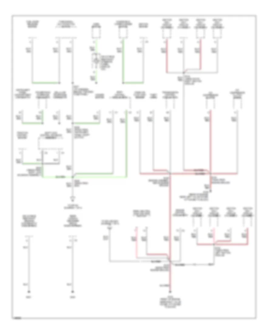
Ground Distribution Wiring Diagram (3 of 3) for Pontiac GTO 2005
 https://portal-diagnostov.com/license.html
Automotive Electricians Portal FZCO
Automotive Electricians Portal FZCO
https://portal-diagnostov.com/license.html
https://portal-diagnostov.com/license.html
Automotive Electricians Portal FZCO
Automotive Electricians Portal FZCOList of elements for Ground Distribution Wiring Diagram (3 of 3) for Pontiac GTO 2005:
- (430mm from door lock switch) s301
- (above the transmission) g300
- (not used) electro- chromatic mirror connector
- (w/ spoiler) center high mounted stop lamp (chmsl)
- Audio amplifier
- Center high mounted stop lamp (chmsl)
- Door lock cylinder switch
- Driver door lock actuator
- Driver door lock ajar indicator switch
- Driver memory seat module
- Fuel pump/ sender assembly
- G900 (right rear tail lamp stud)
- G901 (center of vehicle, below deck lid)
- Left back-up lamp
- Left rear turn signal lamp
- Left tail/ stop lamp
- Left vanity mirror lamp
- License lamp
- Master window switch
- Nca
- Outside rearview mirror switch
- Passenger door lock actuator
- Passenger door lock ajar indicator switch
- Passenger memory seat module
- Rear compartment lid release actuator
- Rear compartment lid release actuator diode
- Right back-up lamp
- Right rear turn signal lamp
- Right seat memory module)
- Right tail/ stop lamp
- Right vanity mirror lamp
- S221 (driver door, above speaker)
- S222 (above passenger b-pillar)
- S225 (under carpet, under passenger seat)
- S226 (3320mm from body ground)
- S227 (2065mm from right door lock)
- S300 (1570mm from subwoofer amplifier)
- S900 (180mm from fight rear turn signal)
- S901 (200mm from right turn signal lamp)
- S902 (1475mm from back up light lamps)
- S903 (front of under hood fuse panel)
- S904 (1975mm from rear compt release actuator)
- S915 (right side of passenger seat, below door sill)
- S916 (right rear corner of trunk, under tail lamp)
- S917 (behind right quarter trim panel, below quarter glass)
- S920 (behind top rear corner of back seat)
- S921 (right side of trunk, next to fuel tank)
- Seat belt alarm switch
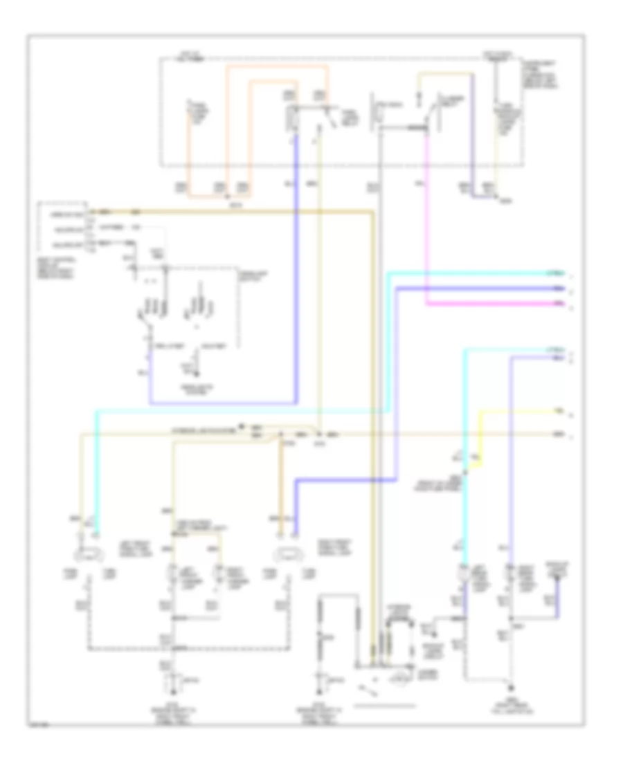
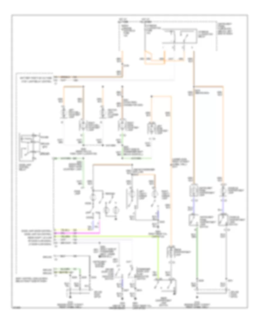
HEADLIGHTS
Headlights Wiring Diagram (1 of 2) for Pontiac GTO 2005
 https://portal-diagnostov.com/license.html
Automotive Electricians Portal FZCO
Automotive Electricians Portal FZCO
https://portal-diagnostov.com/license.html
https://portal-diagnostov.com/license.html
Automotive Electricians Portal FZCO
Automotive Electricians Portal FZCOList of elements for Headlights Wiring Diagram (1 of 2) for Pontiac GTO 2005:
- (behind right rear quarter trim panel, next to rear seat bottom) s265
- (not used)
- Ambient light sensor (on top of dash, under defroster grille)
- Auto
- Battery
- Bcm/engine controls fuse 15a
- Body control module (below right side of dash)
- Brighter
- Computer data lines system
- Darker
- Drl ind
- Exterior lights system
- Fog lamps
- Fog lamps ind
- G102 (engine compt in right front wheel well)
- Gnd
- Hdlmps off
- Hdlmps on
- Hdlp ret
- Hdlp sw
- Head
- Headlamp switch
- High beam ind
- Hot at all times
- I/p dim sw
- Instrument cluster system
- Instrument panel cluster
- Light sensor
- Off
- Park
- Parking brake switch (in center console)
- Prk lp ret
- S105
- S237
- S253 (i/p harness, behind driver information switch)
- S272 (1180mm from head light switch)
- Sp100
- Turn signal/ multifunction switch
- Twilight sentinel enbl sw
- Twilight sentinel enbl sw serial data c2
- Underhood fuse block (on right side of engine compt)
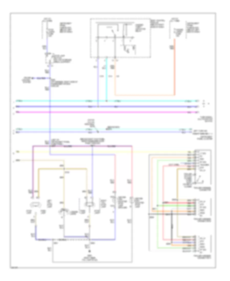
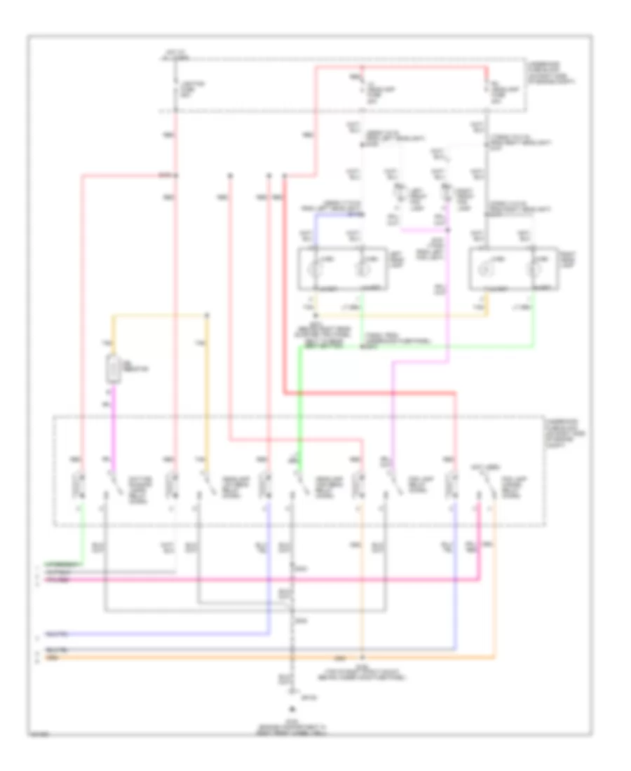
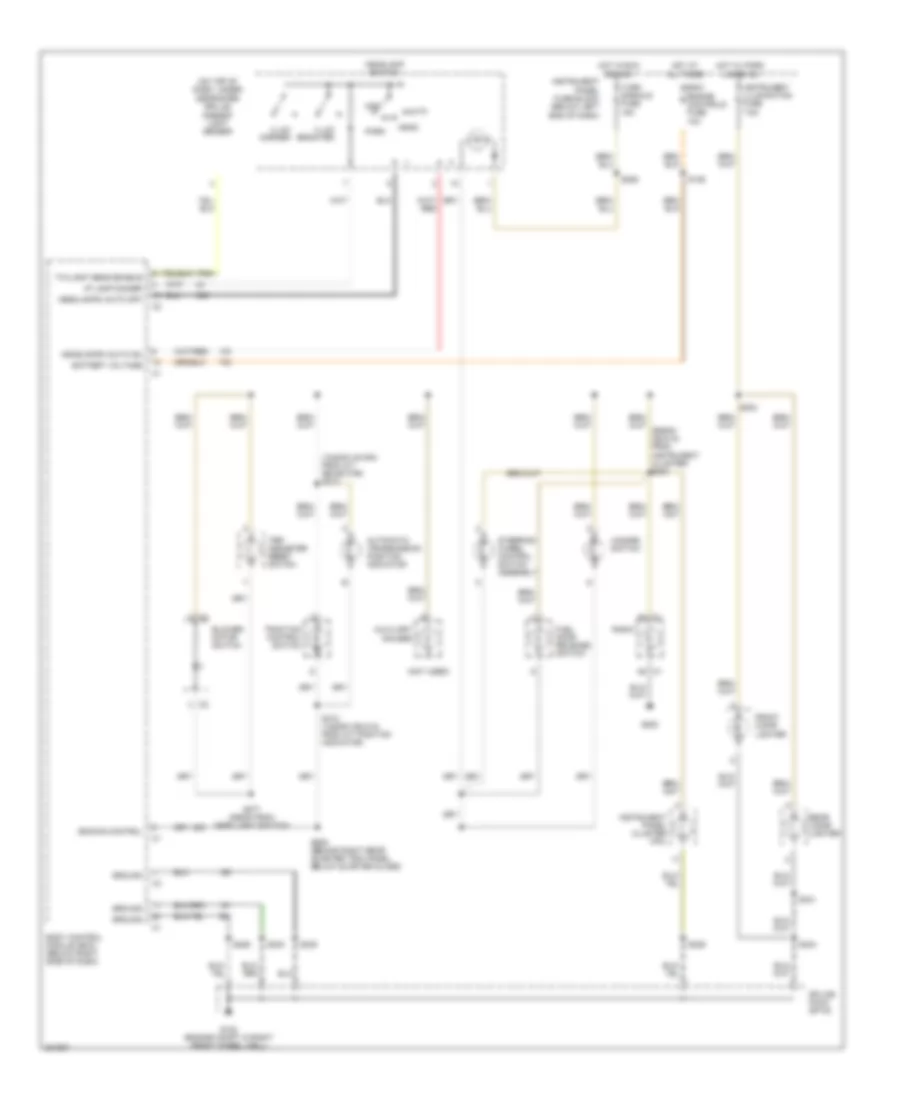
Headlights Wiring Diagram (2 of 2) for Pontiac GTO 2005
 https://portal-diagnostov.com/license.html
Automotive Electricians Portal FZCO
Automotive Electricians Portal FZCO
https://portal-diagnostov.com/license.html
https://portal-diagnostov.com/license.html
Automotive Electricians Portal FZCO
Automotive Electricians Portal FZCOList of elements for Headlights Wiring Diagram (2 of 2) for Pontiac GTO 2005:
- (1785mm (70.2 in) from right headlight) s107
- (375mm (14.8 in) from right headlight) s117
- (455mm (17.9 in) from left headlight) s116
- (455mm (18 in) from left headlight) s108
- (705mm from underhood fuse panel) s274
- (behind right rear quarter trim panel, next to rear seat bottom)
- (not used)
- Daytime running lamps relay (micro)
- Drl resistor
- Fog lamp cancel relay (micro)
- Fog lamp relay (micro)
- G102 (engine compartment in right front wheel well)
- Headlamp high beam relay (micro)
- Headlamp low beam relay (micro)
- Hi-bm
- Hi-ret
- Hot at all times
- Left front fog lamp
- Left head- lamp
- Lh headlamp fuse 20a
- Lighting fuse 60a
- Lo-bm
- Lo-ret
- Red
- Rh headlamp fuse 20a
- Right front fog lamp
- Right head- lamp
- S100
- S150 (top of right strut mount, behind under hood fuse panel)
- S151 (170mm from left fog light)
- S232
- S233
- S273
- Sp100
- Tan
- Underhood fuse block (on right side of engine compt)
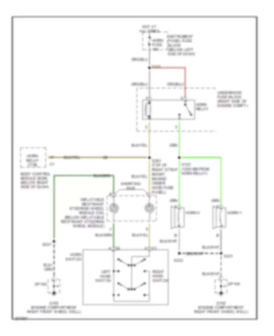
HORN
Horn Wiring Diagram for Pontiac GTO 2005
 https://portal-diagnostov.com/license.html
Automotive Electricians Portal FZCO
Automotive Electricians Portal FZCO
https://portal-diagnostov.com/license.html
https://portal-diagnostov.com/license.html
Automotive Electricians Portal FZCO
Automotive Electricians Portal FZCOList of elements for Horn Wiring Diagram for Pontiac GTO 2005:
- Body control module (bcm) (below right side of dash)
- C1 a
- C2 a
- G102 (engine compartment right front wheel well)
- Horn 1
- Horn 2
- Horn fuse 15a
- Horn relay
- Horn relay ctrl
- Horn switch
- Hot at all times
- Inflatable restraint steering wheel module coil (below inflatable restraint steering wheel module)
- Instrument panel fuse block (below left end of dash)
- Left hand switch
- Right hand switch
- S121
- S123 (1250 mm from horn relay)
- S231
- S233
- S237
- Shorting bar
- Sp100
- Underhood fuse block (right side of engine compt)
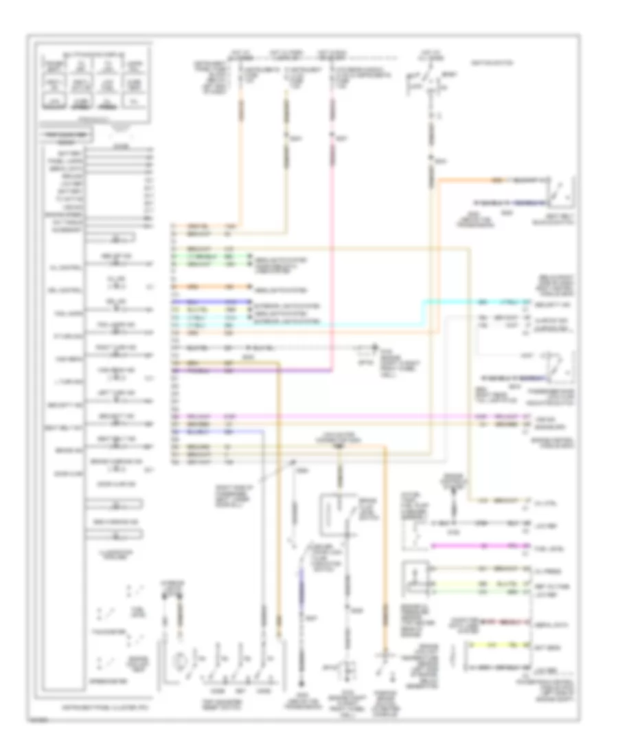
INSTRUMENT CLUSTER
Instrument Cluster Wiring Diagram for Pontiac GTO 2005
 https://portal-diagnostov.com/license.html
Automotive Electricians Portal FZCO
Automotive Electricians Portal FZCO
https://portal-diagnostov.com/license.html
https://portal-diagnostov.com/license.html
Automotive Electricians Portal FZCO
Automotive Electricians Portal FZCOList of elements for Instrument Cluster Wiring Diagram for Pontiac GTO 2005:
- (1910 mm for connector c200) s263
- (above the transmission)
- (below right side of dash) body control module (bcm)
- (in fuel tank) fuel pump & sender assembly
- (right side of passenger seat, under door sill)
- Abs off ind
- Acc
- Accessory
- Ajar sw sig
- Battery
- Brake fluid level switch
- Brake ind
- Brake warning ind
- Chime
- Computer data lines system
- Crctl active
- Crctl on
- Dic toggle
- Door ajar
- Door ajar ind
- Driver door lock ajar indicator switch
- Drl control
- Drl ind
- Ect sens
- Engine control module (ecm)
- Engine controls system
- Engine coolant temp
- Engine coolant temperature sensor (left side of engine, below generator)
- Engine oil pressure sensor (top center rear of engine)
- Engine spd
- Engine speed
- Exterior lights system
- Fog lamps
- Fog lamps ind
- Fuel level
- G102 (engine compt in right front wheel well)
- G300
- G300 (above the transmission)
- G900 (right rear tail lamp stud)
- Ground
- Headlights system
- High beam
- High beam ind
- Hot at all times
- Hot in run or start
- Hot w/ park lamps on
- Htd rear window, hvac & instruments fuse 7.5a
- Ignition switch
- Illumination (6 bulbs)
- Instrument illum fuse 7.5a
- Instrument panel cluster (ipc)
- Instrument panel fuse block (below left end of dash)
- Instruments fuse 10a
- Interior lights system
- L turn sig
- Lamps fail
- Left turn ind
- Lock
- Low coolant
- Low fuel
- Low ref
- Mil
- Mil control
- Mil ctrl
- Mil ind
- Mode
- Multifunction display
- Off
- Oil press
- Over speed
- Over temp
- P r n d 3 2 1
- Panel lamps
- Parking brake switch (in center console)
- Passenger door lock ajar indicator switch
- Power shift
- Powertrain control module (pcm) (left side of engine compt)
- R turn sig
- Ref voltage
- Right turn ind
- S158
- S204
- S207
- S220
- S227
- S229
- S230
- S243
- S264
- S915
- Seat belt buckle switch
- Seat belt ind
- Seat belt sw
- Security ind
- Serial data
- Set
- Sp100
- Speedometer
- Srs warning ind
- Start
- Tachometer
- Tc active
- Tc low
- Tc off
- Trip computer
- Trip odometer reset switch
- Vss sig
INTERIOR LIGHTS
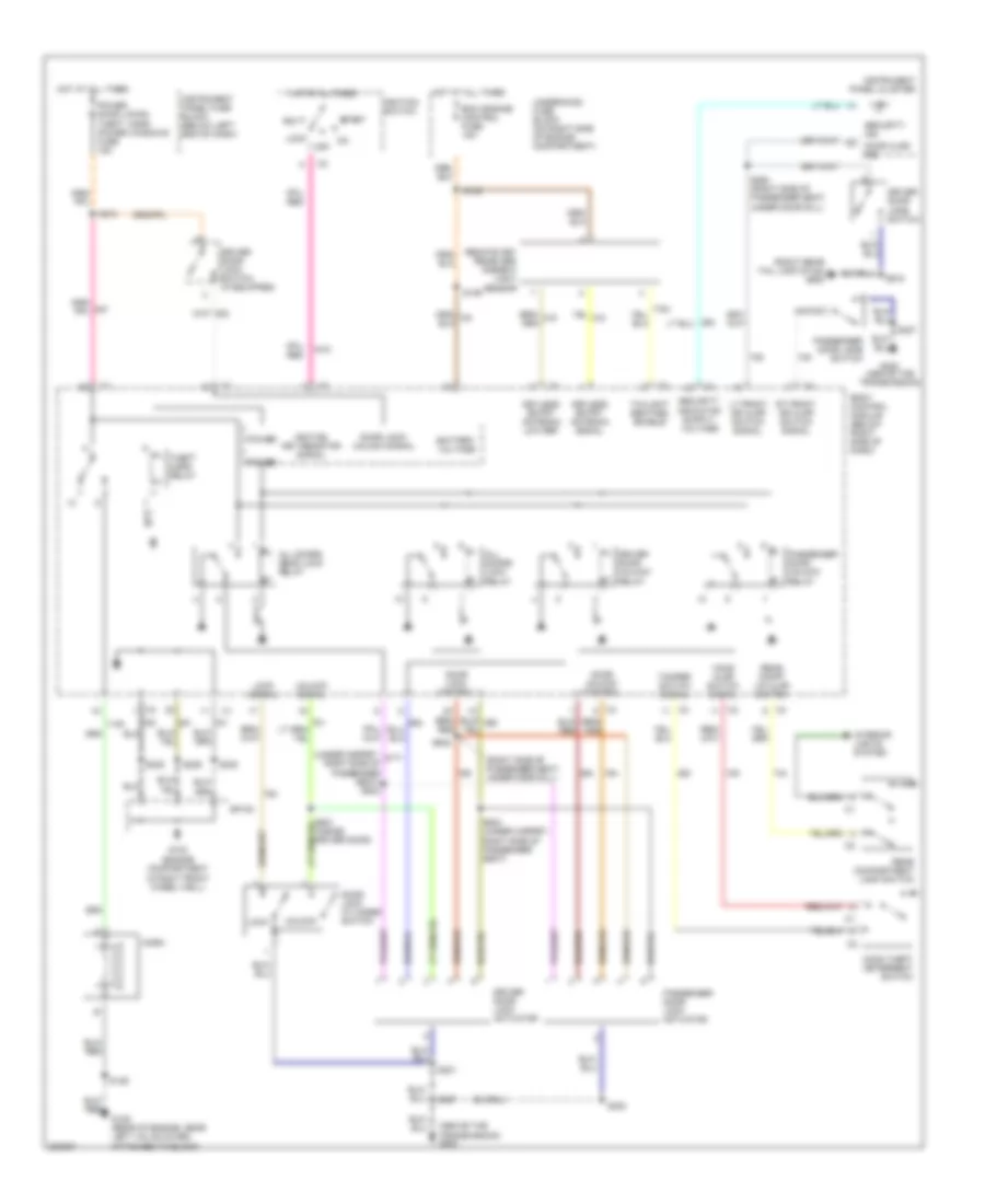
Courtesy Lamps Wiring Diagram for Pontiac GTO 2005
 https://portal-diagnostov.com/license.html
Automotive Electricians Portal FZCO
Automotive Electricians Portal FZCO
https://portal-diagnostov.com/license.html
https://portal-diagnostov.com/license.html
Automotive Electricians Portal FZCO
Automotive Electricians Portal FZCOList of elements for Courtesy Lamps Wiring Diagram for Pontiac GTO 2005:
- (under hood, front of right wheel well) s314
- A c1
- A c2
- Battery positive voltage
- Bcm/ engine controls fuse 10a
- Below door sill)
- Body control module (bcm) (below right side of dash)
- C1 a
- C2 a
- Console compartment lamp
- Console compartment lamp switch
- Ctsy lamp relay control
- Dome
- Dome lamp
- Dome lamp (door control)
- Dome lamp (on control)
- Dome lamp control relay
- Door
- Driver door lock ajar indicator switch
- G102 (engine compt in right front wheel well)
- G300 (above the transmission)
- G900 (right rear tail lamp stud)
- Ground
- Hot at all times
- Ignition lock cylinder lamp
- Instrument cluster system
- Instrument panel compartment lamp
- Instrument panel compartment lamp switch
- Instrument panel fuse block (below left end of dash)
- Interior illumination fuse 10a
- Interior illumination relay
- Left door courtesy lamp
- Left footwell courtesy lamp
- Left vanity mirror lamp
- Lf door ajar signal
- Off
- Passenger door lock ajar indicator switch
- Power
- Reading
- Rear compartment lamp
- Rear compartment lamp switch
- Rear compt lid ajar
- Rf door ajar signal
- Right door courtesy lamp
- Right footwell courtesy lamp
- Right vanity mirror lamp
- S106
- S222
- S227
- S229
- S235
- S236
- S241
- S278 (behind bcm)
- S280 (985mm (38.8 in) form lock illuminator)
- S282 (820mm from right door courtesy lamp)
- S915
- Seat, under door sill)
- Splice pack sp100
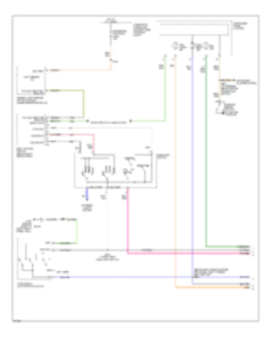
Instrument Illumination Wiring Diagram for Pontiac GTO 2005
 https://portal-diagnostov.com/license.html
Automotive Electricians Portal FZCO
Automotive Electricians Portal FZCO
https://portal-diagnostov.com/license.html
https://portal-diagnostov.com/license.html
Automotive Electricians Portal FZCO
Automotive Electricians Portal FZCOList of elements for Instrument Illumination Wiring Diagram for Pontiac GTO 2005:
- (1040mm (40.9in) from a/t selector) s313
- (not used)
- (on top of dash, under defroster grille)
- A6 c1
- A8 c1
- Ambient light sensor
- Auto
- Automatic transmission position indicator
- Auxiliary gauges
- Battery voltage
- Bcm/ engine controls fuse 10a
- Blower motor switch
- Body control module (bcm) (below right side of dash)
- Dimming control
- Front cigar lighter
- Fuel door release switch
- G102 (engine compt in right front wheel well)
- G200
- Ground
- Hazard switch
- Head
- Headlamp switch
- Headlamps (auto off)
- Headlamps (auto on)
- Hot at all times
- Hot in run or acc
- Hot w/ park lamps on
- I/p lamp dimmer
- Illum brighter
- Illum darker
- Instrument illumination fuse 7.5a
- Instrument panel cluster (ipc)
- Instrument panel fuse block (below left end of dash)
- Off
- Park
- Radio
- Rear cigar lighter
- S106
- S203
- S206
- S229
- S234
- S235
- S241
- S277 (890mm from head light switch)
- S295 (behind right rear quarter trim panel, below quarter glass)
- S312 (1420mm (55.9 in) from a/t position indicator)
- Splice pack sp100
- Steering wheel control switch assembly
- Traction control switch
- Trip odometer reset switch
- Turn signals fuse 15a
- Twilight sens enable
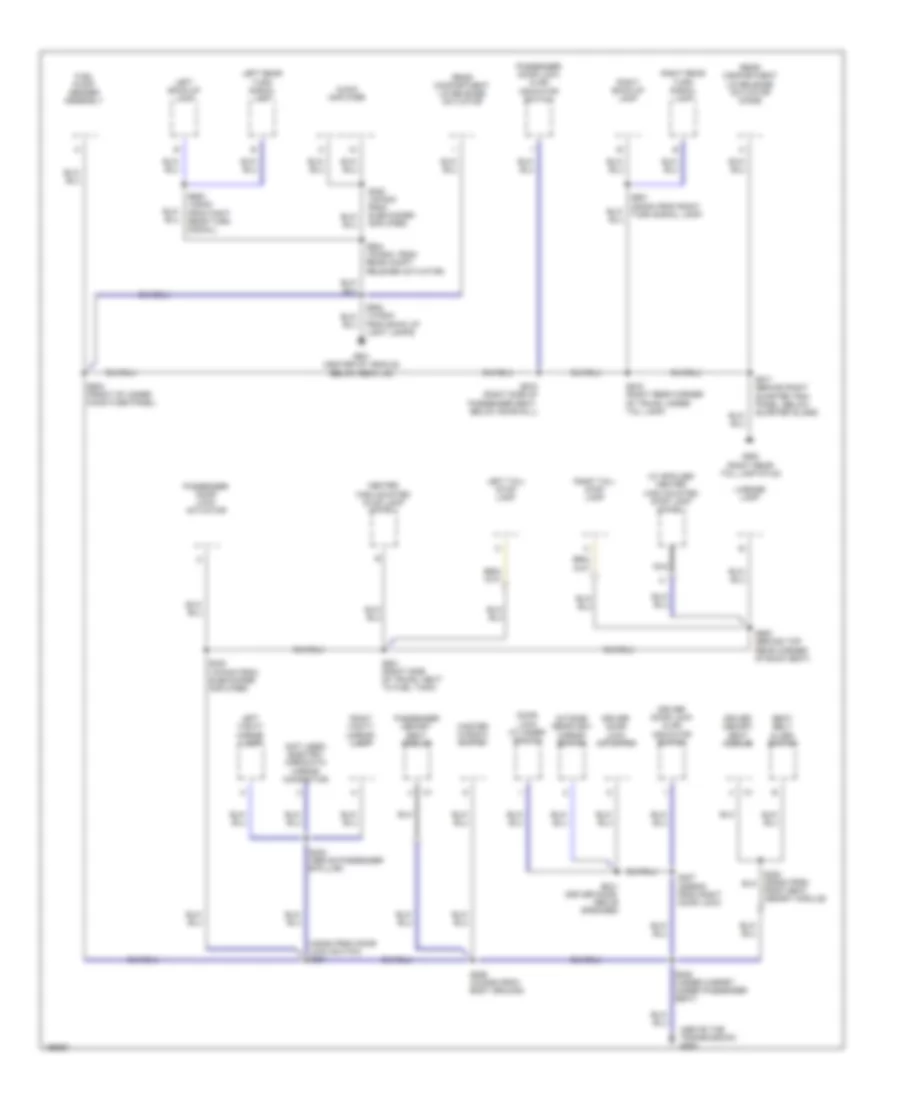
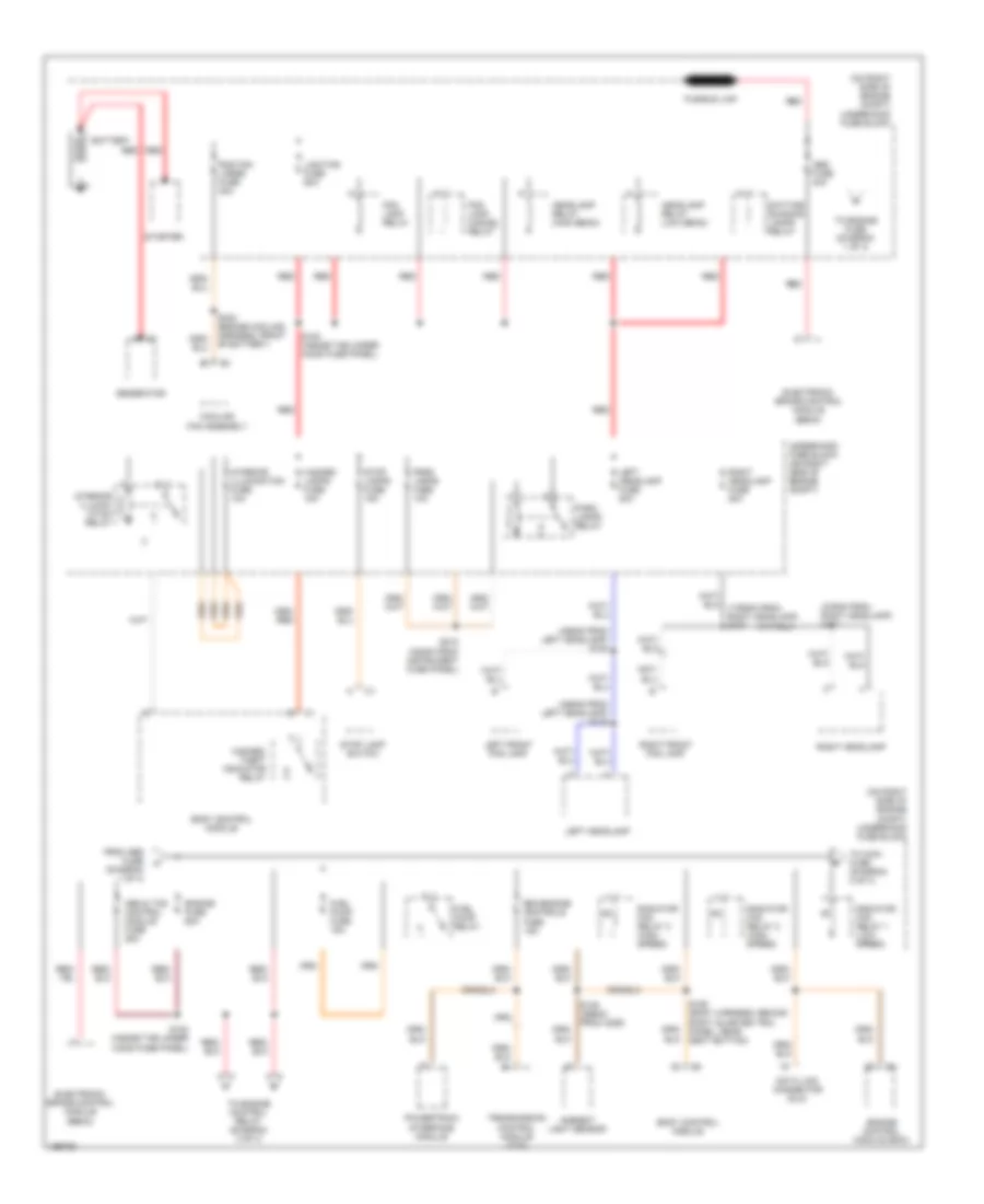
POWER DISTRIBUTION
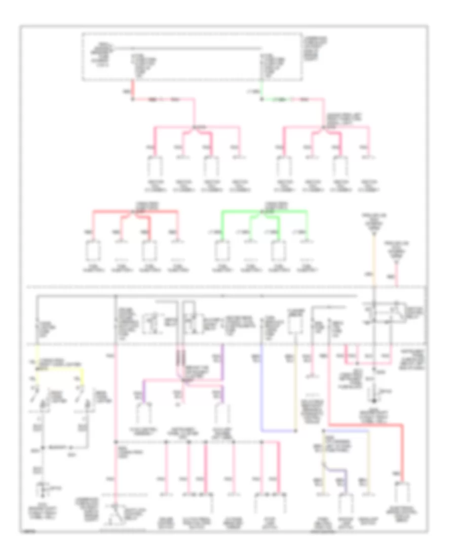
Power Distribution Wiring Diagram (1 of 4) for Pontiac GTO 2005
 https://portal-diagnostov.com/license.html
Automotive Electricians Portal FZCO
Automotive Electricians Portal FZCO
https://portal-diagnostov.com/license.html
https://portal-diagnostov.com/license.html
Automotive Electricians Portal FZCO
Automotive Electricians Portal FZCOList of elements for Power Distribution Wiring Diagram (1 of 4) for Pontiac GTO 2005:
- (375mm from right headlamp) s117
- (455mm from left headlamp) s108
- (455mm from left headlamp) s116
- (on right side of engine compt) underhood fuse block
- Abs & tcs control module fuse 25a
- Abs fuse 40a
- Ambient light sensor
- Battery
- Bcm/engine controls fuse 15a
- Body control module
- C1 a
- Cooling fan assembly
- Data link connector (dlc)
- Daytime running lamps relay
- Electronic brake control module (ebcm)
- Engine control module (ecm)
- Engine fuse 60a
- Fog lamp cancel relay
- Fog lamp relay
- From abs fuse (diagram 1 of 4)
- Fuel pump fuse 15a
- Fuel pump relay
- Fusible link
- Generator
- Hazard lamps fuse 15a
- Hazard/ theft indicator relay
- Headlamp relay (high beam)
- Headlamp relay (low beam)
- Interior illumin- ation relay
- Interior illumination fuse 10a
- Left front fog lamp
- Left headlamp
- Left headlamp fuse 20a
- Lighting fuse 60a
- Park lamps fuse 10a
- Park lamps relay
- Powertrain interface module
- Rad fan large fuse 30a
- Radiator fan relay 1 (low speed)
- Radiator fan relay 2 (high speed)
- Radiator fan relay 3 (high speed)
- Red
- Right front fog lamp
- Right headlamp
- Right headlamp fuse 20a
- S100 (inside the under hood fuse panel)
- S102 (inside the under hood fuse panel)
- S105 (295mm from c206)
- S106 (body harness, behind right quarter trim panel, near seat bottom)
- S165 (engine cooling harness, front of battery)
- S215 (330mm from instrument fuse panel)
- Starter
- Stop lamp switch
- Stop lamps fuse 15a
- To engine control relay (diagram 3 of 4)
- To engine fuse (diagram 1 of 4)
- To main fuse (diagram 2 of 4)
- Transmission control module (tcm)
- Underhood fuse block (on right side of engine compt)
Power Distribution Wiring Diagram (2 of 4) for Pontiac GTO 2005
 https://portal-diagnostov.com/license.html
Automotive Electricians Portal FZCO
Automotive Electricians Portal FZCO
https://portal-diagnostov.com/license.html
https://portal-diagnostov.com/license.html
Automotive Electricians Portal FZCO
Automotive Electricians Portal FZCOList of elements for Power Distribution Wiring Diagram (2 of 4) for Pontiac GTO 2005:
- (1455mm from right power seat) s200
- (2945mm from underhood fuse panel) s103
- (310mm from cell phone connector) s209
- (below left end of dash) instrument panel fuse block
- (i/p harness, behind driver information switch) s210
- (i/p harness, behind driver information switch) s217
- (left side of trunk, near hinge) s267
- Acc socket fuse 20a
- Accessory control relay
- Accessory power outlet
- Audio amplifier
- Auxiliary gauges (not used)
- Blower fan fuse 40a
- Blower fuse 30a
- Blower motor
- Blower motor inline fuse holder
- Blower relay
- Body control module
- Body control module (bcm)
- Cellular phone connector
- Defog relay
- Driver's memory seat module
- From engine fuse (diagram 1 of 4)
- Front washer & wiper circuit breaker 20a
- Fuel door release actuator
- G102 (engine compt in right front wheel well)
- Heated rear window fuse 30a
- Horn fuse 15a
- Horn relay
- Ignition switch fuse 7.5a
- Instrument panel cluster
- Instruments fuse 10a
- Main fuse 60a
- Passenger's memory seat module
- Power door locks, theft, horn, power windows fuse 15a
- Power seats circuit breaker 20a
- Power window relay
- Power windows circuit breaker 20a
- Rad fan small fuse 30a
- Radiator fan relay 3 (high speed)
- Radio
- Radio cellular phone fuse 7.5a
- Radio, cellular phone fuse 15a
- Red
- S104
- S114 (inside under hood fuse panel)
- S121 (top of right strut mount, behind under hood fuse panel)
- S202 (/p harness, behind ignition switch)
- S211 (665mm from instrument fuse panel)
- S216 (555mm from radio)
- S241
- S293 (behind cluster)
- S295 (behind right rear quarter trim panel, below quarter glass)
- Sp100
- Spare fuse
- Start relay
- Sub woofer amplifier fuse 20a
- To ecm signal fuse (diagram 3 of 4)
- To ignition control relay (diagram 4 of 4)
- To ignition switch (diagram 3 of 4)
- Underhood fuse block (on right side of engine compt)
- Windshield wiper motor
- Windshield wiper/ washer switch
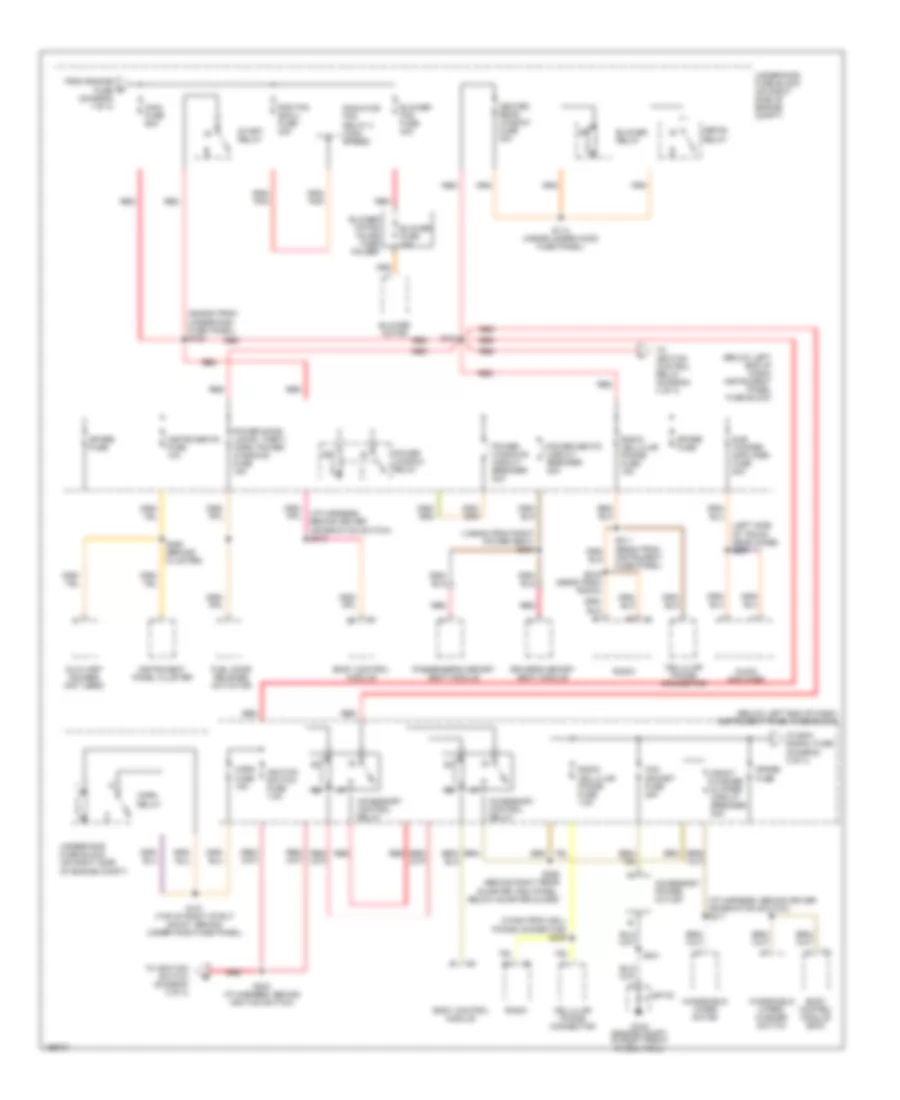
Power Distribution Wiring Diagram (3 of 4) for Pontiac GTO 2005
 https://portal-diagnostov.com/license.html
Automotive Electricians Portal FZCO
Automotive Electricians Portal FZCO
https://portal-diagnostov.com/license.html
https://portal-diagnostov.com/license.html
Automotive Electricians Portal FZCO
Automotive Electricians Portal FZCOList of elements for Power Distribution Wiring Diagram (3 of 4) for Pontiac GTO 2005:
- (490mm from connector c206) s245
- (top of right strut mount, behind under hood fuse panel) s111
- A/c compressor clutch relay
- A/t
- Acc
- Auto trans fuse 15a
- Automatic transmission
- Body control module
- Body control module (bcm)
- Ecm signal fuse 7.5a
- Ecm/tcm control relay 1
- Ecm/tcm control relay 2
- Engine control module
- Engine control module (ecm)
- Engine control relay
- Engine sensors fuse 15a
- Evaporative emissions (evap) canister purge solenoid
- Evaporative emissions (evap) canister vent solenoid
- From splice s102 (diagram 1 of 4)
- From splice s202 (diagram 2 of 4)
- G102 (engine compt in right front wheel well)
- Heated oxygen sensor (ho2s) bank 1 sensor 1
- Heated oxygen sensor (ho2s) bank 1 sensor 2
- Heated oxygen sensor (ho2s) bank 2 sensor 1
- Heated oxygen sensor (ho2s) bank 2 sensor 2
- Ignition switch
- Instrument panel cluster (ipc)
- Instrument panel fuse block (below left end of dash)
- Lock
- M/t
- Mass airflow (maf) sensor
- Off
- Pnk
- Pnk/ (750mm from skip shift solenoid) s110
- Powertrain interface module (pim)
- Red
- Reverse lockout solenoid
- Run
- S109 (right rear of engine)
- S237
- S243 (behind the cluster)
- S246 (105mm from oil pressure sensor)
- S289 (i/p harness, left side of steering column)
- S290 (i/p harness, left side of steering column)
- Shiftlock control solenoid assembly
- Skip shift coil assembly
- Sp100
- Start
- Start relay
- Stop lamp switch
- Tan
- The cluster)
- To fuel injectors & ignition module fuse (diagram 4 of 4)
- To ignition control relay (diagram 4 of 4)
- To spare fuse (diagram 2 of 4)
- Transmission control module (tcm)
- Underhood fuse block (on right side of engine compt)
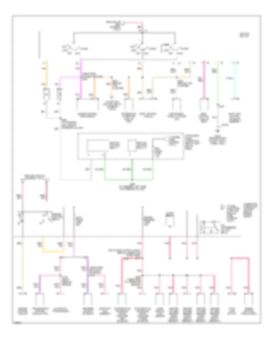
Power Distribution Wiring Diagram (4 of 4) for Pontiac GTO 2005
 https://portal-diagnostov.com/license.html
Automotive Electricians Portal FZCO
Automotive Electricians Portal FZCO
https://portal-diagnostov.com/license.html
https://portal-diagnostov.com/license.html
Automotive Electricians Portal FZCO
Automotive Electricians Portal FZCOList of elements for Power Distribution Wiring Diagram (4 of 4) for Pontiac GTO 2005:
- (150mm from injector 3) s138
- (155mm from injector 6) s137
- (2240mm from left front park/turn signal light) s155
- (behind the instrument cluster) s207
- Abs & tcs fuse 10a
- Auxiliary gauges (not used)
- Backup lamp switch
- Blower inhibit relay
- Cigar lighter fuse 20a
- Clutch pedal position (cpp) switch
- Cruise control switch
- Cruise control, power mirrors & shiftlock control fuse 10a
- Defog relay
- Electronic brake control module (ebcm)
- Flasher relay
- From engine f sensors fuse (diagram 3 of 4)
- From splice s104 (diagram 2 of 4)
- From splice s244 (diagram 3 of 4)
- Front cigar lighter
- Fuel injector 1
- Fuel injector 2
- Fuel injector 3
- Fuel injector 4
- Fuel injector 5
- Fuel injector 6
- Fuel injector 7
- Fuel injector 8
- Fuel injectors & ignition module fuse 15a
- Fuse panel)
- G102 (engine compt in right front wheel well)
- Headlamp switch
- Heated rear window, hvac & instruments fuse 7.5a
- Hvac control assembly
- Ignition coil cylinder 1
- Ignition coil cylinder 2
- Ignition coil cylinder 3
- Ignition coil cylinder 4
- Ignition coil cylinder 5
- Ignition coil cylinder 6
- Ignition coil cylinder 7
- Ignition coil cylinder 8
- Ignition control relay
- Inflatable restraint sensing & diagnostic control module
- Instrument panel cluster (ipc)
- Instrument panel fuse block (below left end of dash)
- Outside rearview mirror
- Park/ neutral position (pnp) switch
- Pnk
- Rear cigar lighter
- Red
- S154
- S208 (1245mm from c200)
- S213 (105mm from instrument panel fuse block)
- S234
- S238
- S241
- Shiftlock control relay
- Sp100
- Srs fuse 15a
- Stop- lamp switch
- Turn signals & backup lamps fuse 15a
- Underhood fuse block (on right side of engine compt)
POWER MIRRORS
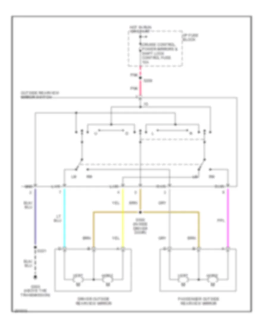
Power Mirrors Wiring Diagram for Pontiac GTO 2005
 https://portal-diagnostov.com/license.html
Automotive Electricians Portal FZCO
Automotive Electricians Portal FZCO
https://portal-diagnostov.com/license.html
https://portal-diagnostov.com/license.html
Automotive Electricians Portal FZCO
Automotive Electricians Portal FZCOList of elements for Power Mirrors Wiring Diagram for Pontiac GTO 2005:
- Cruise control, power mirrors & shift lock control fuse 10a
- Driver outside rearview mirror
- G300 (above the transmission)
- Gnd
- Horiz
- Hot in run or start
- I/p fuse block
- L hr
- L vr
- Outside rearview mirror switch
- Passenger outside rearview mirror
- Pnk
- R hr
- R vr
- S208
- S221
- S500 (in side driver door)
- Vert
POWER SEATS
Driver Power Seat Wiring Diagram for Pontiac GTO 2005
 https://portal-diagnostov.com/license.html
Automotive Electricians Portal FZCO
Automotive Electricians Portal FZCO
https://portal-diagnostov.com/license.html
https://portal-diagnostov.com/license.html
Automotive Electricians Portal FZCO
Automotive Electricians Portal FZCOList of elements for Driver Power Seat Wiring Diagram for Pontiac GTO 2005:
- Battery b+
- Down
- Driver memory seat module
- Driver seat adjuster switch
- Driver seat entry position switch
- Driver seat front vertical motor
- Driver seat horizontal motor
- Driver seat rear vertical motor
- Driver seat recline motor
- Driver seat return position switch
- Front vertical
- Fwd
- G300 (above the transmission)
- Gnd
- Ground
- Horizontal
- Horizontal fwd sw sig
- Horizontal motor fwd
- Horizontal motor rwd
- Horizontal rwd sw sig
- Hot at all times
- Instrument panel fuse block (below left end of dash)
- Passenger presence detection sensor (driver)
- Power seats circuit breaker 20a
- Presence detection
- Pwr
- Rear vertical
- Recline
- Recline fwd sw sig
- Recline motor fwd
- Recline motor rwd
- Recline rwd sw sig
- Red
- Rwd
- S200
- S220
- Seat entry position sw
- Seat return position sw
- Seat switch low ref
- Shaft encoder
- Tan
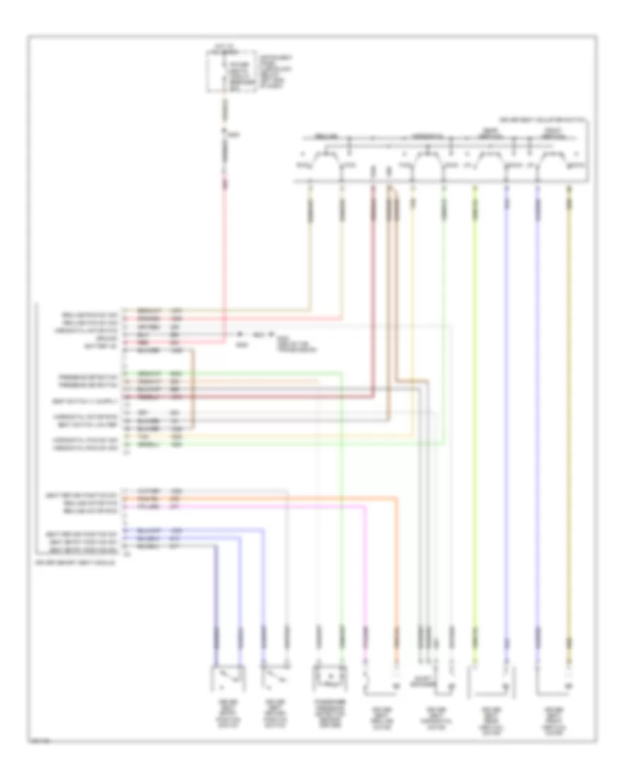
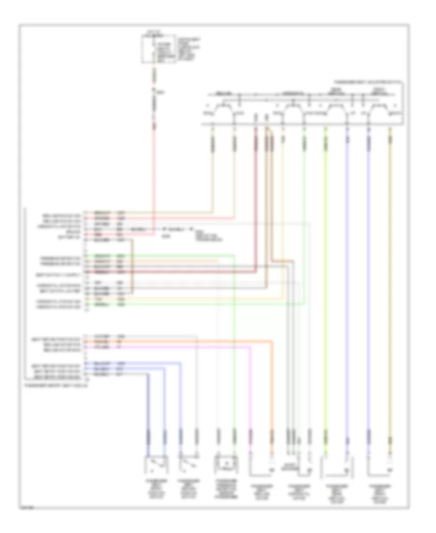
Passenger Power Seat Wiring Diagram for Pontiac GTO 2005
 https://portal-diagnostov.com/license.html
Automotive Electricians Portal FZCO
Automotive Electricians Portal FZCO
https://portal-diagnostov.com/license.html
https://portal-diagnostov.com/license.html
Automotive Electricians Portal FZCO
Automotive Electricians Portal FZCOList of elements for Passenger Power Seat Wiring Diagram for Pontiac GTO 2005:
- Battery b+
- Down
- Front vertical
- Fwd
- G300 (above the transmission)
- Gnd
- Ground
- Horizontal
- Horizontal fwd sw sig
- Horizontal motor fwd
- Horizontal motor rwd
- Horizontal rwd sw sig
- Hot at all times
- Instrument panel fuse block (below left end of dash)
- Passenger memory seat module
- Passenger presence detection sensor (passenger)
- Passenger seat adjuster switch
- Passenger seat entry position switch
- Passenger seat front vertical motor
- Passenger seat horizontal motor
- Passenger seat rear vertical motor
- Passenger seat recline motor
- Passenger seat return position switch
- Power seats circuit breaker 20a
- Presence detection
- Pwr
- Rear vertical
- Recline
- Recline fwd sw sig
- Recline motor fwd
- Recline motor rwd
- Recline rwd sw sig
- Red
- Rwd
- S200
- S226
- Seat entry position sw
- Seat return position sw
- Seat switch low ref
- Shaft encoder
- Tan
POWER WINDOWS
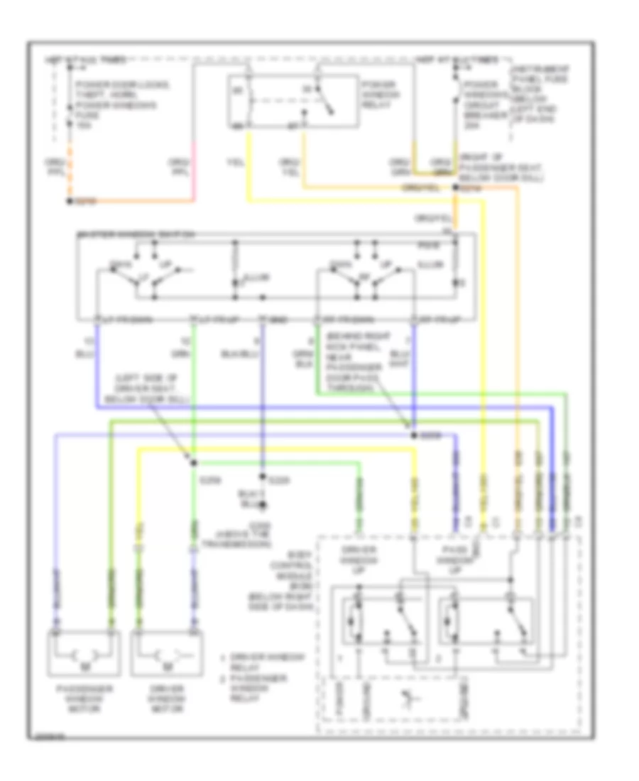
Power Windows Wiring Diagram for Pontiac GTO 2005
 https://portal-diagnostov.com/license.html
Automotive Electricians Portal FZCO
Automotive Electricians Portal FZCO
https://portal-diagnostov.com/license.html
https://portal-diagnostov.com/license.html
Automotive Electricians Portal FZCO
Automotive Electricians Portal FZCOList of elements for Power Windows Wiring Diagram for Pontiac GTO 2005:
- (behind right kick panel, near passenger door pass through)
- (left side of driver seat, below door sill)
- Body control module (bcm) (below right side of dash)
- Driver window
- Driver window motor
- Driver window up
- Dwn
- G300 (above the transmission)
- Gnd
- Ground
- Hot at all times
- Illum
- Instrument panel fuse block (below left end of dash)
- Lt fr dwn
- Lt fr up
- Master window switch
- Pass window up
- Passenger window motor
- Power
- Power door locks, theft, horn, power windows fuse 15a
- Power window relay
- Power windows circuit breaker 20a
- Pwr
- Relay passenger
- Rt fr dwn
- Rt fr up
- S210
- S226
- S258
- S259
- Window relay
RADIO
Radio Wiring Diagram for Pontiac GTO 2005
 https://portal-diagnostov.com/license.html
Automotive Electricians Portal FZCO
Automotive Electricians Portal FZCO
https://portal-diagnostov.com/license.html
https://portal-diagnostov.com/license.html
Automotive Electricians Portal FZCO
Automotive Electricians Portal FZCOList of elements for Radio Wiring Diagram for Pontiac GTO 2005:
- (830mm from connector c200)
- (above passenger "b"-pillar) s315
- (behind right rear quarter glass)
- (behind right rear quarter trim panel, behind pass door)
- Accy voltage
- Ant dfg
- Antenna sig
- Antenna solid state
- Audio amplifier
- Audio rtn sig
- Battery
- Body control module (below right side of dash)
- C10
- C11
- C12
- C13
- C14
- C15
- C16
- C17
- C18
- C19
- C20
- Cell mic sig
- Cell phn mute sig
- Cellular telephone connector
- Computer data lines systems
- Defogger systems
- Dfg
- Drain wire
- G200
- G400
- G901 (center of vehicle, below deck lid)
- Gnd
- Ground
- Hot at all times
- Hot in acc and run
- Hot w/ park lamps on
- I/p lamp voltage
- Inflatable restraint steering wheel module coil (below inflatable restraint steering wheel module)
- Instrument illum fuse 7.5a
- Instrument panel fuse block (below left end of dash)
- Left front door speaker
- Left front speaker
- Left rear speaker
- Left rear subwoofer speaker
- Lf speaker (+)
- Lf speaker (-)
- Lr speaker (+)
- Lr speaker (-)
- Lr subwfr (+)
- Lr subwfr (-)
- Mode
- Mute
- Nca
- Next dwn
- Next up
- Pnk
- Radio
- Radio cellular phone fuse 15a
- Radio cellular phone fuse 7.5a
- Radio on sig
- Rear window defogger & radio antenna module
- Rear window defogger grid & radio antenna
- Rf speaker (+)
- Rf speaker (-)
- Right front door speaker
- Right front speaker
- Right rear speaker
- Right rear subwoofer speaker
- Rr speaker (+)
- Rr speaker (-)
- Rr subwfr (+)
- Rr subwfr (-)
- S204
- S209
- S216
- S267
- S268
- S269 (i/p harness, right of center air vent)
- S270 (800mm from connector c200)
- S271
- S300
- S308 (right side of passenger seat, under door sill)
- S309 (right side of passenger seat, under door sill)
- S310
- S311
- Shorting clip
- Sig
- Steering wheel control switch assembly
- Strng whl ctrl sig
- Sub-woofer amplifier fuse 20a
- Tan
- Uart ser data
- Vol dwn
- Vol up
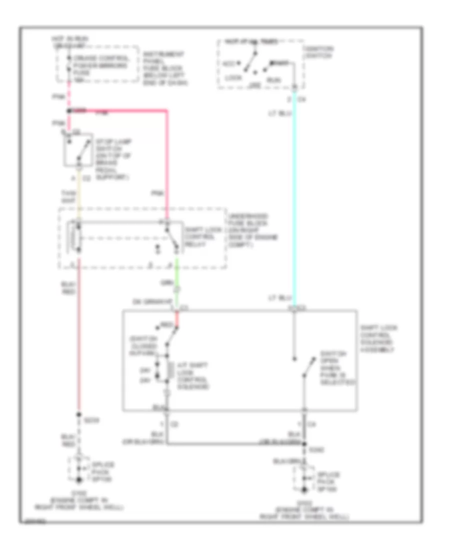
SHIFT INTERLOCK
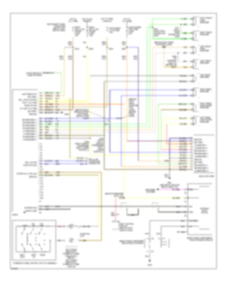
Shift Interlock Wiring Diagram for Pontiac GTO 2005
 https://portal-diagnostov.com/license.html
Automotive Electricians Portal FZCO
Automotive Electricians Portal FZCO
https://portal-diagnostov.com/license.html
https://portal-diagnostov.com/license.html
Automotive Electricians Portal FZCO
Automotive Electricians Portal FZCOList of elements for Shift Interlock Wiring Diagram for Pontiac GTO 2005:
- (switch closed in park)
- 24v
- A c2
- A/t shift lock control solenoid
- Acc
- B c2
- Cruise control, power mirrors fuse 10a
- G102 (engine compt in right front wheel well)
- Hot at all times
- Hot in run or start
- Ignition switch
- Instrument panel fuse block (below left end of dash)
- Lock
- Off
- Pnk
- Red
- Run
- S208
- S239
- S242
- Shift lock control relay
- Shift lock control solenoid assembly
- Splice pack sp100
- Start
- Stop lamp switch (on top of brake pedal support)
- Switch open when park is selected
- Underhood fuse block (on right side of engine compt)
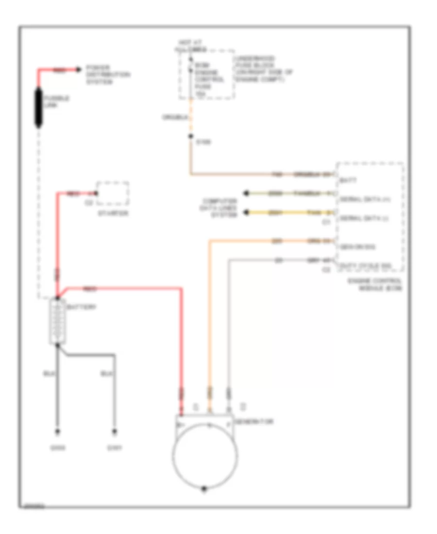
STARTING/CHARGING
Charging Wiring Diagram for Pontiac GTO 2005
 https://portal-diagnostov.com/license.html
Automotive Electricians Portal FZCO
Automotive Electricians Portal FZCO
https://portal-diagnostov.com/license.html
https://portal-diagnostov.com/license.html
Automotive Electricians Portal FZCO
Automotive Electricians Portal FZCOList of elements for Charging Wiring Diagram for Pontiac GTO 2005:
- Batt
- Battery
- Bcm/ engine control fuse 15a
- C2 generator
- Computer data lines system
- Duty cycle sig
- Engine control module (ecm)
- Fusible link
- G100
- G101
- Gen on sig
- Hot at all times
- Power distribution system
- Red
- S106
- Serial data (+)
- Serial data (-)
- Starter
- Tan
- Underhood fuse block (on right side of engine compt)
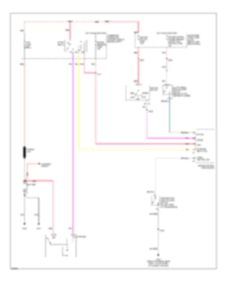
Starting Wiring Diagram for Pontiac GTO 2005
 https://portal-diagnostov.com/license.html
Automotive Electricians Portal FZCO
Automotive Electricians Portal FZCO
https://portal-diagnostov.com/license.html
https://portal-diagnostov.com/license.html
Automotive Electricians Portal FZCO
Automotive Electricians Portal FZCOList of elements for Starting Wiring Diagram for Pontiac GTO 2005:
- A c1
- Acc
- B c1
- Battery
- Charging circuit
- Clutch pedal position (cpp) switch (above clutch master cylinder)
- Crank
- Cruise control power mirrors & shiftlock control fuse 10a
- Engine control module (ecm)
- Engine sensors fuse 15a
- Fusible link
- G100
- G101
- G104 (front of engine, near right valve cover, attached to block)
- Hot in run or start
- Ign 1
- Ignition switch
- Ignition switch fuse 7.5a
- Instrument panel fuse block (below left end of dash)
- Lock
- Main fuse 60a
- Off
- Park/ neutral sig
- Park/neutral position (pnp) switch (on left side of transmission)
- Pnk
- Red
- Relay coil
- Run
- S103
- S104
- S111
- S128
- S202
- S208
- S245
- Start
- Start relay
- Starter
- Starter s
- Sw sig
- Underhood fuse block (on right side of engine compt)
SUPPLEMENTAL RESTRAINTS
Supplemental Restraints Wiring Diagram for Pontiac GTO 2005
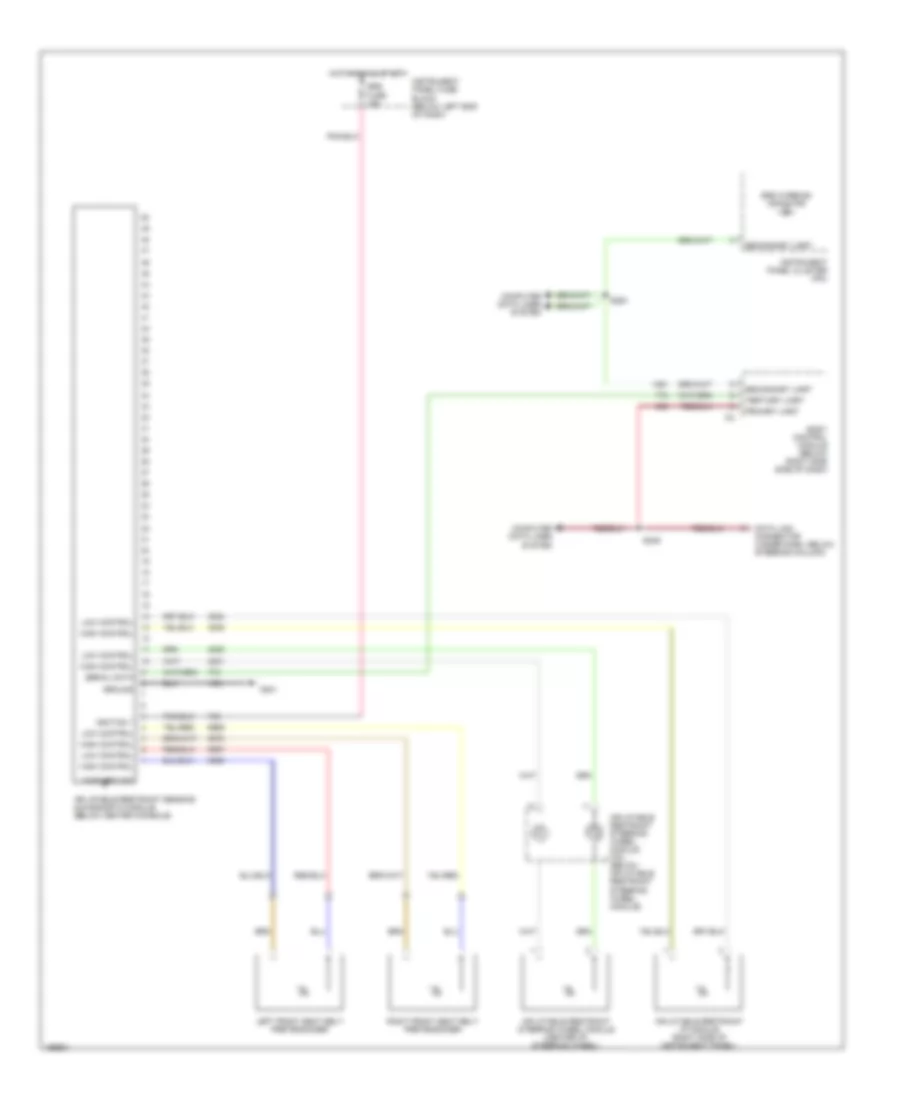 https://portal-diagnostov.com/license.html
Automotive Electricians Portal FZCO
Automotive Electricians Portal FZCO
https://portal-diagnostov.com/license.html
https://portal-diagnostov.com/license.html
Automotive Electricians Portal FZCO
Automotive Electricians Portal FZCOList of elements for Supplemental Restraints Wiring Diagram for Pontiac GTO 2005:
- Body control module (below right side side of dash)
- Case ground
- Computer data lines system
- Data link connector (under dash, below steering column)
- G301
- Ground
- High control
- Hot in run & start
- Ignition 1
- Inflatable restraint i/p module (right side of instrument panel)
- Inflatable restraint sensing & diagnostic module (below center console)
- Inflatable restraint steering wheel module (center of steering wheel)
- Inflatable restraint steering wheel module coil (below inflatable restraint steering wheel module)
- Instrument panel cluster (ipc)
- Instrument panel fuse block (below left end of dash)
- Left front seat belt pretensioner
- Low control
- Primary uart
- Right front seat belt pretensioner
- S249
- S253
- Secondary uart
- Serial data
- Srs fuse 15a
- Srs warning indicator
- Tertiary uart
TRANSMISSION
A/T Wiring Diagram (1 of 2) for Pontiac GTO 2005
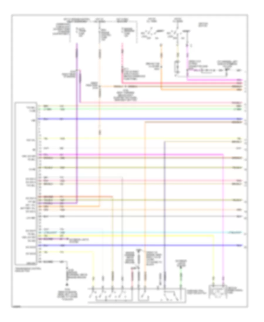 https://portal-diagnostov.com/license.html
Automotive Electricians Portal FZCO
Automotive Electricians Portal FZCO
https://portal-diagnostov.com/license.html
https://portal-diagnostov.com/license.html
Automotive Electricians Portal FZCO
Automotive Electricians Portal FZCOList of elements for A/T Wiring Diagram (1 of 2) for Pontiac GTO 2005:
- (490mm (18.9 in) from connector c206) s245
- (behind the cluster)
- (engine harness, above engine ground)
- (front of engine, near right valve cover, attached to block)
- (i/p harness, left side of steering column) s290
- (not used)
- (top of right strut mount, behind underhood fuse panel)
- 1-2 ss
- 2-3 ss
- Acc
- Acc vol
- Auto trans fuse 15a
- Battery vol
- Bcm/ engine control fuse 15a
- Engine sensors fuse 15a
- Exterior lights system
- G104
- G105 (rear of engine, near left valve cover, attached to block)
- Ground
- Hot at all times
- Hot in run or start
- Hot w/ engine control relay energized
- Ign 1 vol
- Ignition switch
- Lock
- Low ref
- Off
- Park/neutral position switch
- Pc sol
- Pnk
- S106 (body harness, behind right quarter trim panel, near seat bottom)
- S109 (right rear of engine)
- S111 pnk
- S129
- S129 (engine harness, above engine ground)
- S244
- Start
- Sw sig
- Sw sig a
- Sw sig b
- Sw sig c
- Sw sig p
- Tan
- Tcc sol
- Tft ss
- Transmission control module (tcm)
- Underhood fuse block (on right side of engine compartment)
- Vehicle speed signal (vss)
- Vss
- Vss low sig
A/T Wiring Diagram (2 of 2) for Pontiac GTO 2005
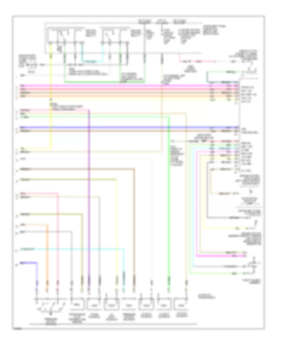 https://portal-diagnostov.com/license.html
Automotive Electricians Portal FZCO
Automotive Electricians Portal FZCO
https://portal-diagnostov.com/license.html
https://portal-diagnostov.com/license.html
Automotive Electricians Portal FZCO
Automotive Electricians Portal FZCOList of elements for A/T Wiring Diagram (2 of 2) for Pontiac GTO 2005:
- (620mm from engine ground) s128
- (above clutch master cylinder) clutch pedal position (cpp) switch
- (engine compt in right front wheel well) g102
- (i/p harness, left of dash fuse panel) s206
- (i/p harness, left side of steering column) s289
- (not used)
- 1-2 shift solenoid
- 2-3 shift solenoid
- 3-2 shift solenoid
- 5v ref
- Acc vol
- Automatic transmission
- Battery vol
- Crank vol
- Cruise control power mirrors & shiftlock control fuse 10a
- Ecm signal fuse 7.5a
- Ecm/tcm control relay 1
- Ecm/tcm control relay 2
- Ect sig
- Engine control module (ecm) (left side of engine compartment)
- Engine coolant temperature (ect) sensor (left side of engine, below generator)
- G104 (front of engine, near right valve cover, attached to block)
- Ground
- Hot at all times
- Hot in run or start
- Ign 1 vol
- Ign 3 vol
- Instrument panel cluster (ipc)
- Instrument panel fuse block (below left end of dash)
- Low ref
- Malfunction indicator lamp
- Mil ctrl
- Panel fuse panel)
- Park/neutral
- Pnk
- Pressure control solenoid
- Pressure switch manifold
- S208 (1245mm from c200)
- S238 (415mm (16.5 in) from turn signal multi function switch)
- Sen 1 sig
- Sen 2 sig
- Sp100
- Tcc en solenoid
- Tcc pwm solenoid
- Throttle body assembly
- Transmission fluid temperature sensor
- Turn signals & back up lamps fuse 15a
- Vss
M/T Wiring Diagram for Pontiac GTO 2005
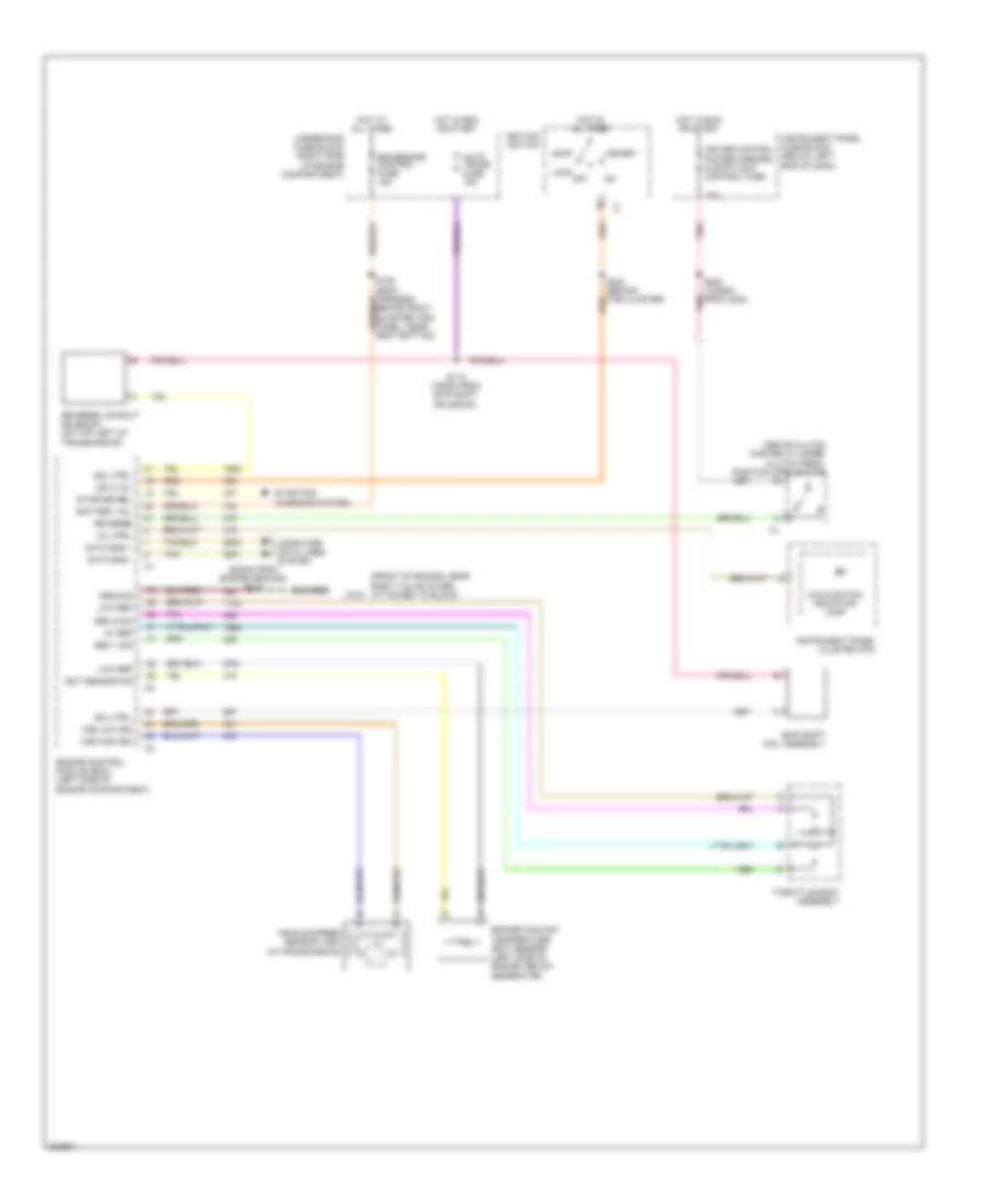 https://portal-diagnostov.com/license.html
Automotive Electricians Portal FZCO
Automotive Electricians Portal FZCO
https://portal-diagnostov.com/license.html
https://portal-diagnostov.com/license.html
Automotive Electricians Portal FZCO
Automotive Electricians Portal FZCOList of elements for M/T Wiring Diagram for Pontiac GTO 2005:
- (620mm from engine ground) s128
- (above clutch master cylinder) clutch pedal position (cpp) switch
- (front of engine, near right valve cover, attached to block)
- 10a
- 5v ref
- Acc
- Auto trans fuse 15a
- Battery vol
- Bcm/engine control fuse 15a
- Computer data lines system
- Cruise control power mirrors & shiftlock control fuse
- Data bus +
- Data bus -
- Ect sensor sig
- Engine control module (ecm) (left side of engine compartment)
- Engine coolant temperature (ect) sensor (left side of engine, below generator)
- G104
- Ground
- Hot at all times
- Hot in run or start
- Ign 3 vol
- Ignition switch
- Instrument panel cluster (ipc)
- Instrument panel fuse block (below left end of dash)
- Lock
- Low ref
- Malfunction indicator lamp
- Mil ctrl
- Off
- Pnk
- Reverse
- Reverse lockout solenoid (on top left of transmission)
- S106 (body harness, behind right quarter trim panel, near seat bottom)
- S110 (750mm from skip shift solenoid)
- S208 (1245mm from c200)
- Sen 1 sig
- Sen 2 sig
- Skip shift coil assembly
- Sol ctrl
- Start
- Starter rel
- Starting/ charging system
- Tan
- Throttle body assembly
- Underhood fuse block (right side of engine compartment)
- Vehicle speed sensor (vss) (in transmission)
- Vss high sig
- Vss low sig
TRUNK, TAILGATE, FUEL DOOR
Trunk, Tailgate, Fuel Door Wiring Diagram for Pontiac GTO 2005
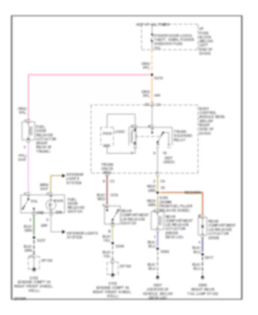 https://portal-diagnostov.com/license.html
Automotive Electricians Portal FZCO
Automotive Electricians Portal FZCO
https://portal-diagnostov.com/license.html
https://portal-diagnostov.com/license.html
Automotive Electricians Portal FZCO
Automotive Electricians Portal FZCOList of elements for Trunk, Tailgate, Fuel Door Wiring Diagram for Pontiac GTO 2005:
- (not used)
- Body control module (bcm) (below right side of dash)
- Dim
- Fuel door release actuator (right rear of trunk)
- Fuel door release switch
- G102 (engine compt in right front wheel well)
- G900 (right rear tail lamp stud)
- G901 (center of vehicle, below deck lid)
- Gnd
- Hot at all times
- I/p fuse block (below left end of dash)
- Interior lights system
- Logic
- Power door locks, theft, horn, power windows fuse 15a
- Pwr
- Rear compartment lid release actuator (inside deck lid)
- Rear compartment lid release actuator diode
- Rear compartment lid release switch
- S210
- S237
- S240
- S305 (300mm from fuel filler release diode)
- S902
- S917
- Sol
- Sp100
- Trunk solenoid relay
- Trunk unlck req
WARNING SYSTEMS
Warning Systems Wiring Diagram for Pontiac GTO 2005
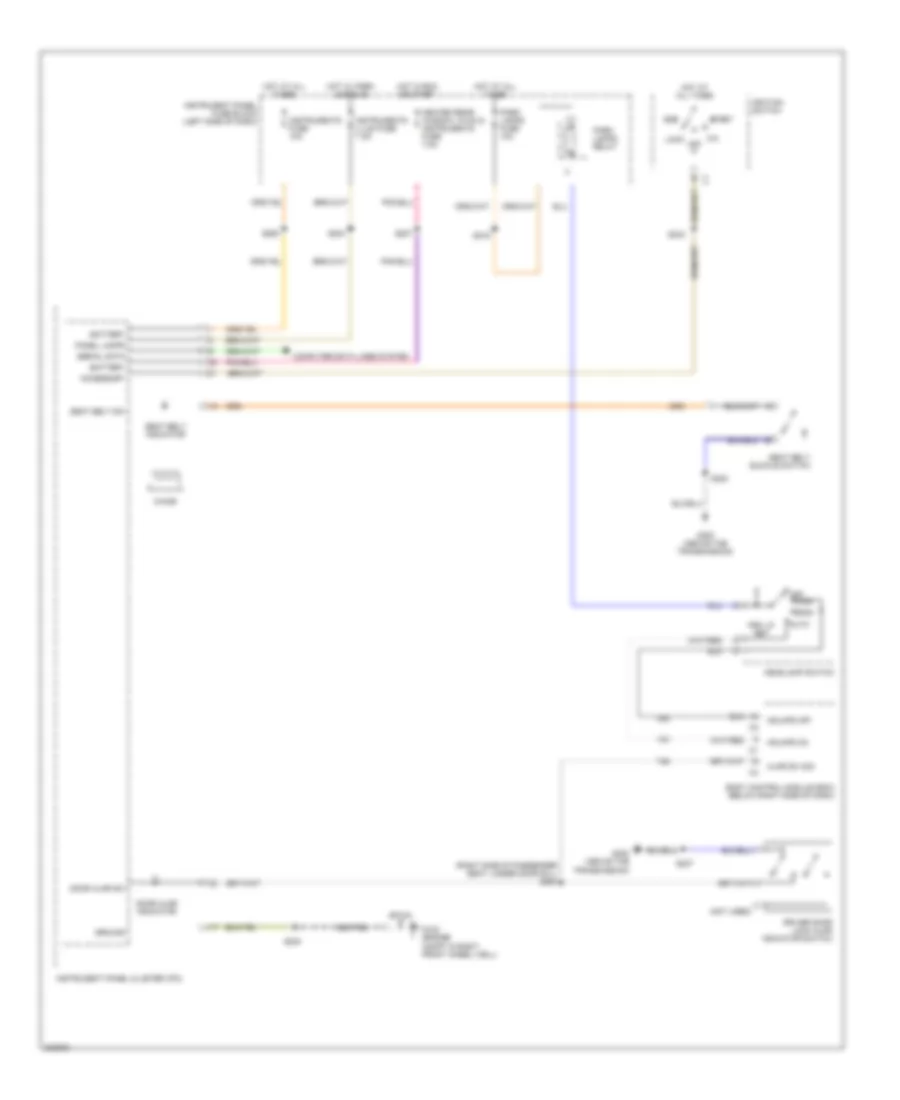 https://portal-diagnostov.com/license.html
Automotive Electricians Portal FZCO
Automotive Electricians Portal FZCO
https://portal-diagnostov.com/license.html
https://portal-diagnostov.com/license.html
Automotive Electricians Portal FZCO
Automotive Electricians Portal FZCOList of elements for Warning Systems Wiring Diagram for Pontiac GTO 2005:
- (not used)
- (right side of passenger seat, under door sill) s264
- Acc
- Accessory
- Ajar sw sig
- Auto
- Battery
- Body control module (bcm) (below right side of dash)
- Chime
- Computer data lines system
- Door ajar indicator
- Door ajar sw
- Driver door lock ajar indicator switch
- G102 (engine compt in right front wheel well)
- G300 (above the transmission)
- Ground
- Hdlmps off
- Hdlmps on
- Head
- Headlamp switch
- Heated rear window, hvac & instruments fuse 7.5a
- Hot at all times
- Hot in run or start
- Hot w/ park lamps on
- Ignition switch
- Instrument panel cluster (ipc)
- Instrument panel fuse block (left side of dash)
- Instruments fuse 10a
- Instruments illum fuse 7.5a
- Lock off
- Off
- Panel lamps
- Park
- Park lamps fuse 10a
- Park lamps relay
- Prk lp ret
- S204
- S207
- S215
- S220
- S227
- S230
- S243
- S293
- Seat belt buckle switch
- Seat belt indicator
- Seat belt sw
- Serial data
- Sp100
- Start
WIPER/WASHER
Wiper/Washer Wiring Diagram for Pontiac GTO 2005
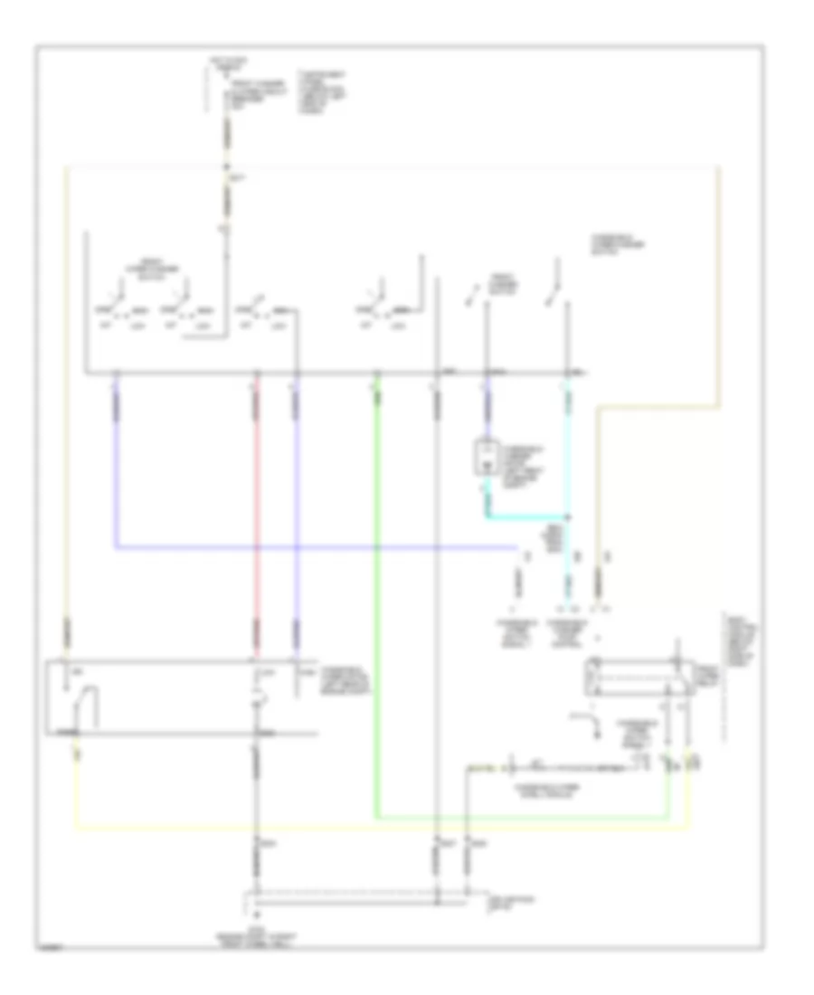 https://portal-diagnostov.com/license.html
Automotive Electricians Portal FZCO
Automotive Electricians Portal FZCO
https://portal-diagnostov.com/license.html
https://portal-diagnostov.com/license.html
Automotive Electricians Portal FZCO
Automotive Electricians Portal FZCOList of elements for Wiper/Washer Wiring Diagram for Pontiac GTO 2005:
- Body control module (below right side of dash)
- Front washer & wiper circuit breaker 20a
- Front washer switch
- Front wiper relay
- Front wiper washer switch
- G102 (engine compt in right front wheel well)
- Gnd
- High
- Hot in acc or run
- Ign
- Instrument panel fuse block (below left end of dash)
- Int
- Low
- Off
- Park
- Rtn
- S217
- S230
- S234
- S237
- S262 (445mm from bcm)
- Splice pack sp100
- Windshield washer motor (left front of engine compt)
- Windshield washer pump control
- Windshield wiper dwell module
- Windshield wiper motor (left rear of engine compt)
- Windshield wiper switch signal 1
- Windshield wiper/washer switch

 Čeština
 Dansk
Dansk Deutsch
 Ελληνικά
 English
 English
 Español
 Suomi
Suomi Français
 Français
 עברית
עברית Hrvatski
 Magyar
 Italiano
 한국어
한국어 Nederlands
 Polski
 Português
 Português
 Română
 Русский
 Slovenčina
 Slovenščina
 Svenska
 Türkçe
 中文 (中国)
