AIR CONDITIONING
Automatic A/C Wiring Diagram (1 of 2) for Toyota Tundra SR 2014
 https://portal-diagnostov.com/license.html
Automotive Electricians Portal FZCO
Automotive Electricians Portal FZCO
https://portal-diagnostov.com/license.html
https://portal-diagnostov.com/license.html
Automotive Electricians Portal FZCO
Automotive Electricians Portal FZCO
List of elements for Automatic A/C Wiring Diagram (1 of 2) for Toyota Tundra SR 2014:
- (left kick panel) j1
- A/c amplifier (right center of dash)
- A/c blower assembly
- A/c control assembly
- A/c evaporator temperature sensor
- A/c fuse 7.5a
- A/c ig fuse 10a
- Ac1
- Act
- Aj10
- Aj3
- Aj5
- Aj9
- B bus
- Blw
- Bus
- Bus g
- Canh
- Canl
- Computer data lines system
- Connector housing color (black)
- Connector housing color (green)
- Connector housing color (natural)
- Connector housing color (red)
- D58
- Damper servo motor (air inlet)
- Damper servo motor (air mix driver side)
- Damper servo motor (air mix front passenger side)
- Damper servo motor (air vent mode)
- Damper servo motor (cool air bypass)
- Defogger rear window
- Defogger system
- Driver side j/b (left end of dash)
- Ecu-ig 2 fuse 7.5a
- Ecu-ig1 4 fuse 7.5a
- Engine room r/b (left side of engine compt)
- Exterior lights system
- Gnd
- Haz
- Hazard switch
- Hot at all times
- Hot in on or start
- Ig+
- Ill+
- Ill-
- Indicator air bag on/off passenger
- Interior lights system
- J/c j60 (left end of dash)
- J/c j64 (left end of dash)
- J106
- J19
- J2 (bottom left center of dash)
- Lin1
- Lock
- Mg clt relay
- Mgc
- Mhtr
- P-ab
- Paon
- Pnk
- Psw
- Rdef
- Red
- Seats system
- Sg 1
- Sg 2
- Sg-6
- Sga
- Sgnd
- Shd+
- Shp+
- Stx
- Svdb
- Svpb
- Switch & mirror heater switch
- Tam
- Tea
- Tsd
- Tsl
- Tsp
- Tsr
Automatic A/C Wiring Diagram (2 of 2) for Toyota Tundra SR 2014
 https://portal-diagnostov.com/license.html
Automotive Electricians Portal FZCO
Automotive Electricians Portal FZCO
https://portal-diagnostov.com/license.html
https://portal-diagnostov.com/license.html
Automotive Electricians Portal FZCO
Automotive Electricians Portal FZCO
List of elements for Automatic A/C Wiring Diagram (2 of 2) for Toyota Tundra SR 2014:
- (left side of engine compt) j/c a49
- (right side of dash) blower motor
- 4.0l
- 4.6l
- A/c compressor (lower left front of engine)
- A/c pressure switch (left front of engine compt)
- A2 (left front of engine compt)
- A24
- Ac1
- Act
- Aj3
- Aj7
- Ambient temperature sensor (left side of front grille)
- Automatic light control sensor (top center of dash)
- Canh
- Canl
- Computer data lines system
- D74
- Da3
- E2 ethw
- Engine control module (right rear of engine compt)
- Engine controls system
- Engine coolant temperature sensor (except 4.0l: front of left cylinder bank) (4.0l: rear of right cylinder bank)
- Engine room j/b (left side of engine compt)
- Except 4.0l
- Except 4.6l
- Gnd
- Hot at all times
- Htr fuse 50a
- J3 (right kick panel)
- Lock sensor
- Magnetic clutch
- Mg+
- Pnk
- Red
- Room temperature sensor (lower left center of dash)
- Solar sensor
- Ssr+
- Ssr-
- Thw
- Tsl
- Tsr
Manual A/C Wiring Diagram (1 of 2) for Toyota Tundra SR 2014
 https://portal-diagnostov.com/license.html
Automotive Electricians Portal FZCO
Automotive Electricians Portal FZCO
https://portal-diagnostov.com/license.html
https://portal-diagnostov.com/license.html
Automotive Electricians Portal FZCO
Automotive Electricians Portal FZCO
List of elements for Manual A/C Wiring Diagram (1 of 2) for Toyota Tundra SR 2014:
- (left kick panel) j1
- A/c amplifier (right center of dash)
- A/c blower assembly
- A/c control assembly
- A/c evaporator temperature sensor
- A/c fuse 7.5a
- A/c ig fuse 10a
- Ac1
- Act
- Aj10
- Aj3
- Aj5
- Aj9
- B bus
- Blw
- Bus
- Bus g
- Canh
- Canl
- Computer data lines system
- Connector housing color (black)
- Connector housing color (green)
- Connector housing color (red)
- D58
- Damper servo motor (air inlet)
- Damper servo motor (air mix driver side)
- Damper servo motor (air mix front passenger side)
- Damper servo motor (air vent mode)
- Defogger rear window
- Defogger system
- Driver side j/b (left end of dash)
- Ecu-ig 2 fuse 7.5a
- Ecu-ig1 4 fuse 7.5a
- Engine room r/b (left side of engine compt)
- Exterior lights system
- Gnd
- Haz
- Hazard switch
- Hot at all times
- Hot in on or start
- Ig+
- Ill+
- Ill-
- Indicator air bag on/off passenger
- Interior lights system
- J/c j60 (left end of dash)
- J/c j64 (left end of dash)
- J106
- J19
- J2 (bottom left center of dash)
- Lin1
- Lock
- Mg clt relay
- Mgc
- Mhtr
- P-ab
- Paon
- Pnk
- Psw
- Rdef
- Red
- Seats system
- Sg 2
- Sg-6
- Sga
- Sgnd
- Shd+
- Shp+
- Stx
- Svdp
- Svpb
- Switch & mirror heater switch
- Tam
- Tea
- Tsl
- Tsr
Manual A/C Wiring Diagram (2 of 2) for Toyota Tundra SR 2014
 https://portal-diagnostov.com/license.html
Automotive Electricians Portal FZCO
Automotive Electricians Portal FZCO
https://portal-diagnostov.com/license.html
https://portal-diagnostov.com/license.html
Automotive Electricians Portal FZCO
Automotive Electricians Portal FZCO
List of elements for Manual A/C Wiring Diagram (2 of 2) for Toyota Tundra SR 2014:
- (left side engine compt) j/c a49
- 4.0l
- 4.6l
- A/c compressor (lower left front of engine)
- A/c pressure switch (left front of engine compt)
- A2 (left front of engine compt)
- A24
- Ac1
- Act
- Aj3
- Aj7
- Ambient temperature sensor (left side of front grille)
- Blower motor (right side of dash)
- Canh
- Canl
- Computer data lines system
- D74
- Da3
- E2 ethw
- Engine control module (right rear of engine compt)
- Engine controls system
- Engine coolant temperature sensor (except 4.0l: front of left cylinder bank) (4.0l: rear of right cylinder bank)
- Engine room j/b (left side of engine compt)
- Except 4.0l
- Except 4.6l
- Gnd
- Hot at all times
- Htr fuse 50a
- J3 (right kick panel)
- Lock sensor
- Magnetic clutch
- Mg+
- Pnk
- Red
- Ssr+
- Ssr-
- Thw
ANTI-LOCK BRAKES
Anti-lock Brakes Wiring Diagram (1 of 2) for Toyota Tundra SR 2014
 https://portal-diagnostov.com/license.html
Automotive Electricians Portal FZCO
Automotive Electricians Portal FZCO
https://portal-diagnostov.com/license.html
https://portal-diagnostov.com/license.html
Automotive Electricians Portal FZCO
Automotive Electricians Portal FZCO
List of elements for Anti-lock Brakes Wiring Diagram (1 of 2) for Toyota Tundra SR 2014:
- +bm
- +bs
- A2 (left front of engine compt)
- Active brake booster (left rear of engine compt)
- Aj10
- Ab1
- Ab2
- B17
- Brk relay
- Bst
- Bstp
- Bsw
- Canh
- Canl
- Computer data lines system
- Cruise control system
- Csw
- D/g
- D56
- Driver side j/b (left end of dash)
- Ecu ig 1 fuse 7.5a
- Engine room r/b (left side of engine compt)
- Exi2
- Fl+
- Fl-
- Fr+
- Fr-
- Gnd1
- Gyaw
- Hot in on or start
- Ig1
- J/c a49 (left side of engine compt)
- J/c a50 (left end of dash)
- J/c a51 (right end of dash)
- Left front speed sensor (left front wheel hub assembly)
- Left rear speed sensor (left rear wheel hub assembly)
- Pa1
- Pim
- Pkb2
- Pnk
- Psnc
- Psno
- Ra5
- Red
- Right front speed sensor (right front wheel hub assembly)
- Right rear speed sensor (right rear wheel hub assembly)
- Rl+
- Rl-
- Rr+
- Rr-
- Rb1
- Skid control ecu w/ actuator (left side of engine compt)
- Sp1
- Ss1
- Ss2
- Stp
- Stp2
- Stpo
- Sts
- Vcp
- Vys
- Yaw rate sensor (under center console)
- Yaw1
- Yaw2
Anti-lock Brakes Wiring Diagram (2 of 2) for Toyota Tundra SR 2014
 https://portal-diagnostov.com/license.html
Automotive Electricians Portal FZCO
Automotive Electricians Portal FZCO
https://portal-diagnostov.com/license.html
https://portal-diagnostov.com/license.html
Automotive Electricians Portal FZCO
Automotive Electricians Portal FZCO
List of elements for Anti-lock Brakes Wiring Diagram (2 of 2) for Toyota Tundra SR 2014:
- (left front of engine compt) a1
- (left front of engine compt) j/c a44
- 4wd control ecu (if equipped) (right end of dash)
- 5v +b
- 5v ic
- A2 (left front of engine compt)
- A25
- Abs1 fuse 50a
- Abs2 fuse 40a
- Add
- Add actuator (4wd) (front of engine)
- Aj10
- Aj9
- B11
- B13
- B14
- B21
- Bat
- Brake fluid level warning switch (brake master cylinder)
- Buzzer
- Can i/f
- Canh
- Canl
- Combination meter
- Computer data lines system
- Cpu
- D14
- D3 (right rear of engine)
- Da4
- Dg1
- Display color tft (if equipped)
- Driver side j/b (left end of dash)
- Ecu b1 fuse 7.5a
- Engine room r/b (left side of engine compt)
- Ess
- Gnd
- Hot at all times
- Hot in on or start
- I/f
- Ig+
- Interior lights system
- J/c j61 (left side of dash)
- J/c j70 & j71 (left center of dash)
- J3 (right kick panel)
- J70
- J71
- Led driver
- Met fuse 7.5a
- Met-b fuse 5a
- Parking brake switch (base of parking brake lever assembly)
- Pedal stroke speed sensor (brake master cylinder assembly)
- Pim
- Pnk
- Red
- Steering angle sensor (steering column)
- Stop fuse 15a
- Stop light switch (top of brake pedal assembly)
- Telltale
- Vcp
- Vsc off switch
ANTI-THEFT
Forced Entry Wiring Diagram (1 of 2) for Toyota Tundra SR 2014
 https://portal-diagnostov.com/license.html
Automotive Electricians Portal FZCO
Automotive Electricians Portal FZCO
https://portal-diagnostov.com/license.html
https://portal-diagnostov.com/license.html
Automotive Electricians Portal FZCO
Automotive Electricians Portal FZCO
List of elements for Forced Entry Wiring Diagram (1 of 2) for Toyota Tundra SR 2014:
- (center of dash) j/c j73 & j72
- (left center of dash) j/c j70 & j71
- (right "b" pillar) q1
- A1 (left front of engine compt)
- A2 (left front of engine compt)
- A24
- Acc
- Acc fuse 7.5a
- Act+
- Act-
- Actd
- Aj10
- Aj2
- Aj9
- Altb
- B13
- B18
- B21
- Becu
- Bk/up lp fuse 10a
- Bzr
- C23
- C24
- Canh
- Canl
- Computer data lines system
- D14
- D40
- D49
- D51
- D52
- D53
- D55
- D65
- D74
- Da4
- Dcty
- Detection unlock
- Diode (ignition) (left side of dash)
- Dr/lck fuse 25a
- Driver side j/b (left end of dash)
- Ecu ig 2 fuse 7.5a
- Engine control module (right rear of engine compt)
- Exterior lights system
- Gbs
- Gnd1
- Gnd2
- Haz
- Hcty
- Headlights system
- Horn
- Horns system
- Hot at all times
- Hot in on or acc
- Hot in on or start
- Hrly
- Ile
- Ind
- Interior lights system
- J/c d73 (right rear of engine compt)
- J/c j64 (left end of dash)
- J/c j70 (left center of dash)
- J/c j72 & j73 (center of dash)
- J1 (left kick panel)
- J70
- J71
- J72
- J73
- Key lock
- Key unlock
- Ksw
- Lcty
- Left front door courtesy switch (left "b" pillar)
- Left front door lock motor
- Lh ig fuse 7.5a
- Lswd
- Lswl
- Lswp
- Lswr
- Main body ecu (on driver side junction block)
- Nj1
- Nj2
- Oq1
- Park/neutral position switch (transmission assembly)
- Pcty
- Pj2
- Pnk
- Prg
- Qj1
- Qj2
- Rda
- Red
- Right front door courtesy switch (right "b" pillar)
- Right rear door courtesy switch (right "c" pillar)
- Right rear door lock motor
- Rrcy
- Trly
- Ul1
- Ul3
- Unlock detection
- Unlock warning switch (steering column)
- W/ column shift
- W/ floor shift
- Wireless door lock buzzer (left front of engine compt)
Forced Entry Wiring Diagram (2 of 2) for Toyota Tundra SR 2014
 https://portal-diagnostov.com/license.html
Automotive Electricians Portal FZCO
Automotive Electricians Portal FZCO
https://portal-diagnostov.com/license.html
https://portal-diagnostov.com/license.html
Automotive Electricians Portal FZCO
Automotive Electricians Portal FZCO
List of elements for Forced Entry Wiring Diagram (2 of 2) for Toyota Tundra SR 2014:
- (left "b" pillar) p1
- (left "c" pillar)
- (left side of dash) glass breakage sensor ecu
- (right kick panel) j3
- (right side of engine compt) a3
- Aj10
- Cab
- Can i/f
- Combination meter
- Computer data lines system
- Cpu
- D56
- Door control receiver (except regular cab: right "c" pillar) (regular cab: right "b" pillar)
- Door lock switch
- Driver side j/b (left end of dash)
- Ecu b1 fuse 7.5a
- Ecu ig1 fuse 7.5a
- Engine hood courtesy switch (center front of engine compt)
- Engine room r/b (left side of engine compt)
- Except regular
- Glass breakage sensor microphone (lower center of dash)
- Gnd
- Hot at all times
- Hot in on or start
- J/c a52 (right end of dash)
- J/c j61 (left side of dash)
- J/c j64 (left end of dash)
- J/c j65 (left side of dash)
- J/c j66 (right end of dash)
- J/c j70 (left center of dash)
- J1 (left kick panel)
- J3 (right kick panel)
- Left rear door courtesy switch
- Left rear door lock motor
- Lock
- Met b fuse 5a
- Mic+
- Mic-
- Mj1
- Mj2
- Nca
- Nca mic-
- Nj2
- Op1
- Pnk
- Pnk gbig
- Power window regulator master switch
- Prg
- Q2 (except regular cab: right "c" pillar) (regular cab: right "b" pillar)
- Qj1
- Rda
- Red
- Regular cab
- Right front door lock motor
- Right front door lock switch
- Security horn (right rear of engine compt)
- Security horn relay
- Security ind
- Unlock
- Unlock detection
Immobilizer Wiring Diagram for Toyota Tundra SR 2014
 https://portal-diagnostov.com/license.html
Automotive Electricians Portal FZCO
Automotive Electricians Portal FZCO
https://portal-diagnostov.com/license.html
https://portal-diagnostov.com/license.html
Automotive Electricians Portal FZCO
Automotive Electricians Portal FZCO
List of elements for Immobilizer Wiring Diagram for Toyota Tundra SR 2014:
- (center of dash) j/c j72 & j73
- (left "b" pillar) left front door courtesy switch
- (left end of dash) j/c j64
- (right kick panel) j3
- A24
- Agnd
- Aj5
- Aj9
- B15
- Can i/f
- Code
- Combination meter
- Computer data lines system
- Cpu
- Cty
- D17
- Driver side j/b (left end of dash)
- Efii
- Efio
- Engine control module (right rear of engine compt)
- Engine room r/b (left side of engine compt)
- Gnd
- Hot at all times
- Hot in on or start
- Ign fuse 10a
- Ignition key cylinder light
- Imb fuse 7.5a
- Imi
- Imo
- Ind
- Interior lights system
- J/c a49 (left side of engine compt)
- J/c j61 (left side of dash)
- J/c j65 (left side of dash)
- J/c j72 (left center of dash)
- J1 (left kick panel)
- J3 (right kick panel)
- J72
- J73
- Ksw
- Pj2
- Pnk
- Security
- Transponder key amplifier (at steering column)
- Transponder key coil
- Transponder key ecu (left center of dash)
- Txct
- Unlock warning switch (steering column)
- Vc5
BODY CONTROL MODULES
Body Control Modules Wiring Diagram (1 of 2) for Toyota Tundra SR 2014
 https://portal-diagnostov.com/license.html
Automotive Electricians Portal FZCO
Automotive Electricians Portal FZCO
https://portal-diagnostov.com/license.html
https://portal-diagnostov.com/license.html
Automotive Electricians Portal FZCO
Automotive Electricians Portal FZCO
List of elements for Body Control Modules Wiring Diagram (1 of 2) for Toyota Tundra SR 2014:
- 7.5a
- A1 (left front of engine compt)
- Acc
- Acc fuse 7.5a
- Act+
- Act-
- Altb
- B11
- B13
- B16
- B18
- B21
- Becu
- C23
- C24
- Can
- Canh
- Canl
- Cann
- Canp
- Cglp
- Cgnd
- Cgsw
- Cltb
- Clte
- Clts
- Computer data lines system
- D13
- D14
- D40
- D41
- D49
- D51
- D52
- D53
- Dim
- Domr
- Door locks & anti-theft systems
- Dr/lck fuse 25a
- Driver side j/b (left end of dash)
- Drl
- Ecu b1
- Ecu-ig 2 fuse 7.5a
- Engine room r/b (left side of engine compt)
- Exterior lights & interior lights systems
- Exterior lights system
- Ffog
- Fuse
- Gnd1
- Gnd2
- Haz
- Head
- Headlights & instrument cluster systems
- Headlights system
- Horn
- Horns system
- Hot at all times
- Hot in on or acc
- Hot in on or start
- Hrly
- Ile
- Interior lights system
- J/c j76 (w/ seat position memory) (left end of dash)
- Lcty
- Left front power seat control ecu & switch (under driver's seat)
- Lin2
- Lswl
- Lswp
- Lswr
- Main body ecu (on driver side junction block)
- Memory systems
- Multiplex tilt & telescopic ecu (on steering column)
- Nj3
- Outer mirror control ecu
- P/w relay
- Pcty
- Pj2
- Pkb
- Pnk
- Prg
- Pws
- Pz1
- Rda
- Red
- Ret
- Rrcy
- Trly
- Ul1
- Z10
Body Control Modules Wiring Diagram (2 of 2) for Toyota Tundra SR 2014
 https://portal-diagnostov.com/license.html
Automotive Electricians Portal FZCO
Automotive Electricians Portal FZCO
https://portal-diagnostov.com/license.html
https://portal-diagnostov.com/license.html
Automotive Electricians Portal FZCO
Automotive Electricians Portal FZCO
List of elements for Body Control Modules Wiring Diagram (2 of 2) for Toyota Tundra SR 2014:
- (right center of dash) a/c amplifier
- (right end of dash) (w/ blindspot monitor system) network gateway ecu
- (right side of dash) bus buffer
- (w/o navigation) radio & display receiver assembly (w/ navigation) navigation receiver assembly
- 4wd control ecu (if equipped) (right end of dash)
- A24
- A25
- Actd
- Aj3
- Aj5
- Aj9
- Bzr
- Ca1h
- Ca1l
- Can+
- Can-
- Canh
- Canl
- Center air bag ecu (column shift: bottom center of dash) (floor shift: under front of center console)
- Combination meter
- Dcty
- Dlc 3 (left side of dash)
- Door locks & anti-theft systems
- Engine control module (right rear of engine compt)
- Exterior lights & headlights systems
- Ffgo
- Gbs
- Hcty
- Headlights system
- Ind
- Interior lights system
- J/c j74 (right side of dash)
- J/c j75 (left end of dash)
- J135
- J139
- J19
- J46
- Ksw
- Lswd
- Main body ecu (on driver side junction block)
- Memory systems
- Mirb
- Mire
- Mirs
- Msch
- Mscl
- Pnk
- Red
- Skid control ecu w/ actuator (left side of engine compt)
- Steering angle sensor (steering column)
- Tail
- Ul3
- W/ navigation
- W/o navigation
- Warning systems
COMPUTER DATA LINES
Computer Data Lines Wiring Diagram (1 of 2) for Toyota Tundra SR 2014
 https://portal-diagnostov.com/license.html
Automotive Electricians Portal FZCO
Automotive Electricians Portal FZCO
https://portal-diagnostov.com/license.html
https://portal-diagnostov.com/license.html
Automotive Electricians Portal FZCO
Automotive Electricians Portal FZCO
List of elements for Computer Data Lines Wiring Diagram (1 of 2) for Toyota Tundra SR 2014:
- (right rear of engine) (4.0l) d8 d1 (except 4.0l) (left rear of engine)
- 4wd control ecu (if equipped) (right end of dash)
- A/c amplifier (right center of dash)
- A/c control assembly
- A24
- A25
- A45
- Aj2
- Aj3
- Aj4
- Aj5
- Aj9
- B13
- B15
- Bat
- Batt
- Bus buffer (right side of dash)
- Ca1h
- Ca1l
- Ca1n
- Ca1p
- Ca2h
- Ca2l
- Ca2n
- Ca2p
- Can+
- Can-
- Canh
- Canl
- D14
- D17
- D18
- D56
- D73
- Dia
- Dlc3 (left side of dash)
- Driver side j/b (left end of dash)
- Ecu-b1 fuse 7.5a
- Ecu-ig 1 fuse 7.5a
- Engine control module (right rear of engine compt)
- Engine room r/b (left side of engine compt)
- Gnd
- Hot at all times
- Hot w/ ig 1 relay energized
- Hot w/ ig2 relay energized
- Ig1
- Ig2
- Ign fuse 10a
- J/c a45 & d73 (right rear of engine compt)
- J/c a49 (left side of engine compt)
- J/c j60 (left end of dash)
- J/c j61 (left side of dash)
- J/c j65 (left side of dash)
- J/c j70 & j71 (left center of dash) j71
- J/c j72 & j73 (center of dash)
- J/c j72 & j73 (center of dash) j73
- J/c j72 (center of dash)
- J/c j74 (right side of dash)
- J/c r17 (under right rear of vehicle)
- J1 (left kick panel)
- J135
- J139
- J19
- J3 (right kick panel)
- J70
- J72
- J73
- Junction terminal j77 (right end of dash)
- Left blind spot monitor sensor (left corner of rear bumper)
- Lin1
- Navigation receiver assembly (w/ navigation system) radio & display receiver assembly (w/o navigation system)
- Network gateway ecu (w/ blind spot monitor system) (right end of dash)
- Obd fuse 7.5a
- Occupant detection ecu (under front passenger's seat)
- Pnk
- Qj1
- Qy1
- Ra6
- Red
- Right blind spot monitor sensor (right corner of rear bumper)
- Sil
- Sr2
- Stx
- Tac
- Tach
- Tire pressure warning ecu (right side of dash)
- Transponder key ecu (left center of dash)
- W/ navigation system
- W/o navigation system
Computer Data Lines Wiring Diagram (2 of 2) for Toyota Tundra SR 2014
 https://portal-diagnostov.com/license.html
Automotive Electricians Portal FZCO
Automotive Electricians Portal FZCO
https://portal-diagnostov.com/license.html
https://portal-diagnostov.com/license.html
Automotive Electricians Portal FZCO
Automotive Electricians Portal FZCO
List of elements for Computer Data Lines Wiring Diagram (2 of 2) for Toyota Tundra SR 2014:
- (left end of dash) j/c j75
- Aj10
- Aj9
- Can
- Canh
- Canl
- Cann
- Canp
- Center air bag ecu (column shift: bottom center of dash) (floor shift: under front of center console)
- Cgnd
- Combination meter
- D/g
- J/c j65 (left side of dash)
- J/c j76 (w/ memory) (left end of dash)
- J46
- Jj1
- Jw1
- Left front power seat control ecu & switch (under driver's seat)
- Left front power window regulator motor
- Lin
- Lin1
- Lin2
- Main body ecu (on driver side junction block)
- Mj2
- Msch
- Mscl
- Multiplex tilt & telescopic ecu (on steering column)
- Nj3
- Outer mirror control ecu
- Pj2
- Pnk
- Power window regulator master switch
- Pz1
- Red
- Right front power window regulator motor
- Sil
- Skid control ecu w/ actuator (left side of engine compt)
- Sliding roof control ecu
- Steering angle sensor (steering column)
- W/ auto up
- W/ memory
- Z10
CRUISE CONTROL
4.0L
4.0L, Cruise Control Wiring Diagram (1 of 2) for Toyota Tundra SR 2014
 https://portal-diagnostov.com/license.html
Automotive Electricians Portal FZCO
Automotive Electricians Portal FZCO
https://portal-diagnostov.com/license.html
https://portal-diagnostov.com/license.html
Automotive Electricians Portal FZCO
Automotive Electricians Portal FZCO
List of elements for 4.0L, Cruise Control Wiring Diagram (1 of 2) for Toyota Tundra SR 2014:
- (left end of dash) j/c a50
- (right side of engine compt)
- (top of brake pedal assembly) stop light switch
- +b2
- +bm
- A2 (left front of engine compt)
- A24
- Accelerator pedal position sensor (top of accelerator pedal assembly)
- Aj10
- Aj2
- Aj4
- Batt
- Canh
- Canl
- Ccs
- Column shift
- Computer data lines system
- D74
- D8 (right rear of engine)
- D9 (right rear of engine)
- Da2
- Da4
- Diode (ignition) (left side of dash)
- E01
- E02
- E03
- Efi 1 fuse 25a
- Efi relay
- Engine control module (right rear of engine compt)
- Engine controls system
- Engine room j/b (left side of engine compt)
- Engine room r/b (left side of engine compt)
- Epa
- Epa2
- Eta
- Etcs fuse 10a
- Floor shift
- Ge01
- Hot at all times
- Hot in on or start
- Ign fuse 10a
- Igsw
- J/c a44 (left front of engine compt)
- J/c a49 (left side of engine compt)
- J/c a52 (right end of dash)
- J/c d73 (right rear of engine compt)
- J/c j73 & j72 (center of dash)
- J72
- J73
- Me01
- Met fuse 7.5a
- Met-b fuse 5a
- Mrel
- Park/neutral position switch (transmission assembly)
- Pnk
- Red
- Shield
- Spd
- St1-
- Stop fuse 15a
- Stp
- Throttle position sensor (on throttle body)
- Vcp2
- Vcpa
- Vcta
- Vpa
- Vpa2
- Vta
- Vta1
- Vta2
4.0L, Cruise Control Wiring Diagram (2 of 2) for Toyota Tundra SR 2014
 https://portal-diagnostov.com/license.html
Automotive Electricians Portal FZCO
Automotive Electricians Portal FZCO
https://portal-diagnostov.com/license.html
https://portal-diagnostov.com/license.html
Automotive Electricians Portal FZCO
Automotive Electricians Portal FZCO
List of elements for 4.0L, Cruise Control Wiring Diagram (2 of 2) for Toyota Tundra SR 2014:
- (left side of dash) j/c j61
- (right kick panel) j3
- (w/o tft)
- +res
- -set
- 5v ic
- A45
- Aj3
- Aj5
- Aj9
- Ab1
- Ab2
- Bk/up lp fuse 10a
- Buzzer
- Can i/f
- Cancel
- Canh
- Canl
- Combination meter assembly
- Computer data lines system
- Cpu
- Cruise control main switch
- Cruise control switch
- D55
- D65
- D73
- D8 (right rear of engine)
- Display color tft (w/ tft) display segmented
- Driver side j/b (left end of dash)
- Fl+
- Fl-
- Fr+
- Fr-
- Hot in on or start
- I/f
- Ig+
- J/c a45 & d73 (right rear of engine compt)
- J/c j65 (left side of dash)
- J/c j70 (left center of dash)
- J45
- Led
- Led driver
- Left front speed sensor (left front wheel hub assembly)
- Left rear speed sensor (left rear wheel hub assembly)
- Lh ig fuse 7.5a
- On-off
- Pnk
- Ra5
- Red
- Right front speed sensor (right front wheel hub assembly)
- Right rear speed sensor (right rear wheel hub assembly)
- Rl+
- Rl-
- Rr+
- Rr-
- Rb1
- Skid control ecu w/ actuator (left side of engine compt)
- Sp1
- Spiral cable (steering column)
- Telltale
4.6L
4.6L, Cruise Control Wiring Diagram (1 of 2) for Toyota Tundra SR 2014
 https://portal-diagnostov.com/license.html
Automotive Electricians Portal FZCO
Automotive Electricians Portal FZCO
https://portal-diagnostov.com/license.html
https://portal-diagnostov.com/license.html
Automotive Electricians Portal FZCO
Automotive Electricians Portal FZCO
List of elements for 4.6L, Cruise Control Wiring Diagram (1 of 2) for Toyota Tundra SR 2014:
- (left end of dash) j/c a50
- (left front of engine compt) j/c a44
- (right side of engine compt) a3
- (top of brake pedal assembly) stop light switch
- +b2
- +bm
- A2 (left front of engine compt)
- A24
- Accelerator pedal position sensor (top of accelerator pedal assembly)
- Aj10
- Aj2
- Aj4
- Batt
- Canh
- Canl
- Ccs
- Column shift
- Computer data lines system
- D1 (left rear of engine)
- D2 (rear of engine compt)
- D74
- Da2
- Da4
- Diode (ignition) (left side of dash)
- E03
- Efi 1 fuse 25a
- Efi relay
- Engine control module (right rear of engine compt)
- Engine controls system
- Engine room j/b (left side of engine compt)
- Engine room r/b (left side of engine compt)
- Epa
- Epa2
- Eta
- Etcs fuse 10a
- Floor shift
- Ge01
- Hot at all times
- Hot in on or start
- Ign fuse 10a
- Igsw
- J/c a49 (left side of engine compt)
- J/c a52 (right end of dash)
- J/c d73 (right rear of engine compt)
- J/c j73 & j72 (center of dash)
- J72
- J73
- Me01
- Met b fuse 5a
- Met fuse 7.5a
- Mrel
- Park/neutral position switch (transmission assembly)
- Pnk
- Red
- Spd
- St1-
- Stop fuse 15a
- Stp
- Throttle position sensor (on throttle body)
- Vcp2
- Vcpa
- Vcta
- Vpa
- Vpa2
- Vta1
- Vta2
4.6L, Cruise Control Wiring Diagram (2 of 2) for Toyota Tundra SR 2014
 https://portal-diagnostov.com/license.html
Automotive Electricians Portal FZCO
Automotive Electricians Portal FZCO
https://portal-diagnostov.com/license.html
https://portal-diagnostov.com/license.html
Automotive Electricians Portal FZCO
Automotive Electricians Portal FZCO
List of elements for 4.6L, Cruise Control Wiring Diagram (2 of 2) for Toyota Tundra SR 2014:
- (w/o tft)
- +res
- -set
- 5v ic
- A45
- Aj3
- Aj5
- Aj9
- Ab1
- Ab2
- Bk/up lp fuse 10a
- Buzzer
- Can i/f
- Cancel
- Canh
- Canl
- Combination meter assembly
- Computer data lines system
- Cpu
- Cruise control main switch
- Cruise control switch
- D1 (left rear of engine)
- D55
- D65
- D73
- Display color tft (w/ tft) display segmented
- Driver side j/b (left end of dash)
- Fl+
- Fl-
- Fr+
- Fr-
- Hot in on or start
- I/f
- Ig+
- J/c a45 & d73 (right rear of engine compt)
- J/c j61 (left side of dash)
- J/c j65 (left side of dash)
- J/c j70 (left center of dash)
- J3 (right kick panel)
- J45
- Led
- Led driver
- Left front speed sensor (left front wheel hub assembly)
- Left rear speed sensor (left rear wheel hub assembly)
- Lh ig fuse 7.5a
- On-off
- Pnk
- Ra5
- Red
- Right front speed sensor (right front wheel hub assembly)
- Right rear speed sensor (right rear wheel hub assembly)
- Rl+
- Rl-
- Rr+
- Rr-
- Rb1
- Skid control ecu w/ actuator (left side of engine compt)
- Sp1
- Spiral cable (steering column)
- Telltale
5.7L
5.7L, Cruise Control Wiring Diagram (1 of 2) for Toyota Tundra SR 2014
 https://portal-diagnostov.com/license.html
Automotive Electricians Portal FZCO
Automotive Electricians Portal FZCO
https://portal-diagnostov.com/license.html
https://portal-diagnostov.com/license.html
Automotive Electricians Portal FZCO
Automotive Electricians Portal FZCO
List of elements for 5.7L, Cruise Control Wiring Diagram (1 of 2) for Toyota Tundra SR 2014:
- (left end of dash) j/c a50
- (right side of engine compt) a3
- (top of brake pedal assembly) stop light switch
- +b2
- +bm
- A2 (left front of engine compt)
- A24
- Accelerator pedal position sensor (top of accelerator pedal assembly)
- Aj10
- Aj2
- Aj4
- Batt
- Canh
- Canl
- Ccs
- Column shift
- Computer data lines system
- D1 (left rear of engine)
- D2 (rear of engine compt)
- D74
- Da2
- Da4
- Diode (ignition) (left side of dash)
- E01
- E02
- E03
- E04
- E05
- Efi 1 fuse 25a
- Efi relay
- Engine control module (right rear of engine compt)
- Engine controls system
- Engine room j/b (left side of engine compt)
- Engine room r/b (left side of engine compt)
- Epa
- Epa2
- Eta
- Etcs fuse 10a
- Floor shift
- Ge01
- Hot at all times
- Hot in on or start
- Ign fuse 10a
- Igsw
- J/c a44 (left front of engine compt)
- J/c a49 (left side of engine compt)
- J/c a52 (right end of dash)
- J/c d73 (right rear of engine compt)
- J/c j73 & j72 (center of dash)
- J72
- J73
- Me01
- Met fuse 7.5a
- Met-b fuse 5a
- Mrel
- Park/neutral position switch (transmission assembly)
- Pnk
- Red
- Spd
- St1-
- Stop fuse 15a
- Stp
- Throttle position sensor (on throttle body)
- Vcp2
- Vcpa
- Vcta
- Vpa
- Vpa2
- Vta1
- Vta2
5.7L, Cruise Control Wiring Diagram (2 of 2) for Toyota Tundra SR 2014
 https://portal-diagnostov.com/license.html
Automotive Electricians Portal FZCO
Automotive Electricians Portal FZCO
https://portal-diagnostov.com/license.html
https://portal-diagnostov.com/license.html
Automotive Electricians Portal FZCO
Automotive Electricians Portal FZCO
List of elements for 5.7L, Cruise Control Wiring Diagram (2 of 2) for Toyota Tundra SR 2014:
- (w/o tft)
- +res
- -set
- 5v ic
- A45
- Aj3
- Aj5
- Aj9
- Ab1
- Ab2
- Bk/up lp fuse 10a
- Buzzer
- Can i/f
- Cancel
- Canh
- Canl
- Combination meter assembly
- Computer data lines system
- Cpu
- Cruise control main switch
- Cruise control switch
- D55
- D65
- D73
- D8 (right rear of engine)
- Display color tft (w/ tft) display segmented
- Driver side j/b (left end of dash)
- Fl+
- Fl-
- Fr+
- Fr-
- Hot in on or start
- I/f
- Ig+
- J/c a45 & d73 (right rear of engine compt)
- J/c j61 (left side of dash)
- J/c j65 (left side of dash)
- J/c j70 (left center of dash)
- J3 (right kick panel)
- J45
- Led
- Led driver
- Left front speed sensor (left front wheel hub assembly)
- Left rear speed sensor (left rear wheel hub assembly)
- Lh ig fuse 7.5a
- On-off
- Pnk
- Ra5
- Red
- Right front speed sensor (right front wheel hub assembly)
- Right rear speed sensor (right rear wheel hub assembly)
- Rl+
- Rl-
- Rr+
- Rr-
- Rb1
- Skid control ecu w/ actuator (left side of engine compt)
- Sp1
- Spiral cable (steering column)
- Telltale
5.7L FLEX FUEL
5.7L Flex Fuel, Cruise Control Wiring Diagram (1 of 2) for Toyota Tundra SR 2014
 https://portal-diagnostov.com/license.html
Automotive Electricians Portal FZCO
Automotive Electricians Portal FZCO
https://portal-diagnostov.com/license.html
https://portal-diagnostov.com/license.html
Automotive Electricians Portal FZCO
Automotive Electricians Portal FZCO
List of elements for 5.7L Flex Fuel, Cruise Control Wiring Diagram (1 of 2) for Toyota Tundra SR 2014:
- (left end of dash) j/c a50
- (right side of engine compt) a3
- (top of brake pedal assembly) stop light switch
- +b2
- +bm
- A2 (left front of engine compt)
- A24
- Accelerator pedal position sensor (top of accelerator pedal assembly)
- Aj10
- Aj2
- Aj4
- Batt
- Canh
- Canl
- Ccs
- Column shift
- Computer data lines system
- D1 (left rear of engine)
- D2 (rear of engine compt)
- D74
- Da2
- Da4
- Diode (ignition) (left side of dash)
- E01
- E02
- E03
- E04
- E05
- Efi 1 fuse 25a
- Efi relay
- Engine control module (right rear of engine compt)
- Engine controls system
- Engine room j/b (left side of engine compt)
- Engine room r/b (left side of engine compt)
- Epa
- Epa2
- Eta
- Etcs fuse 10a
- Floor shift
- Ge01
- Hot at all times
- Hot in on or start
- Ign fuse 10a
- Igsw
- J/c a44 (left front of engine compt)
- J/c a49 (left side of engine compt)
- J/c a52 (right end of dash)
- J/c d73 (right rear of engine compt)
- J/c j73 & j72 (center of dash)
- J72
- J73
- Me01
- Met fuse 7.5a
- Met-b fuse 5a
- Mrel
- Park/neutral position switch (transmission assembly)
- Pnk
- Red
- Spd
- St1-
- Stop fuse 15a
- Stp
- Throttle position sensor (on throttle body)
- Vcp2
- Vcpa
- Vcta
- Vpa
- Vpa2
- Vta1
- Vta2
5.7L Flex Fuel, Cruise Control Wiring Diagram (2 of 2) for Toyota Tundra SR 2014
 https://portal-diagnostov.com/license.html
Automotive Electricians Portal FZCO
Automotive Electricians Portal FZCO
https://portal-diagnostov.com/license.html
https://portal-diagnostov.com/license.html
Automotive Electricians Portal FZCO
Automotive Electricians Portal FZCO
List of elements for 5.7L Flex Fuel, Cruise Control Wiring Diagram (2 of 2) for Toyota Tundra SR 2014:
- (w/o tft)
- +res
- -set
- 5v ic
- A45
- Aj3
- Aj5
- Aj9
- Ab1
- Ab2
- Bk/up lp fuse 10a
- Buzzer
- Can i/f
- Cancel
- Canh
- Canl
- Combination meter assembly
- Computer data lines system
- Cpu
- Cruise control main switch
- Cruise control switch
- D55
- D65
- D73
- D8 (right rear of engine)
- Display color tft (w/ tft) display segmented
- Driver side j/b (left end of dash)
- Fl+
- Fl-
- Fr+
- Fr-
- Hot in on or start
- I/f
- Ig+
- J/c a45 & d73 (right rear of engine compt)
- J/c j61 (left side of dash)
- J/c j65 (left side of dash)
- J/c j70 (left center of dash)
- J3 (right kick panel)
- J45
- Led
- Led driver
- Left front speed sensor (left front wheel hub assembly)
- Left rear speed sensor (left rear wheel hub assembly)
- Lh ig fuse 7.5a
- On-off
- Pnk
- Ra5
- Red
- Right front speed sensor (right front wheel hub assembly)
- Right rear speed sensor (right rear wheel hub assembly)
- Rl+
- Rl-
- Rr+
- Rr-
- Rb1
- Skid control ecu w/ actuator (left side of engine compt)
- Sp1
- Spiral cable (steering column)
- Telltale
DEFOGGERS
Front Deicer Wiring Diagram for Toyota Tundra SR 2014
 https://portal-diagnostov.com/license.html
Automotive Electricians Portal FZCO
Automotive Electricians Portal FZCO
https://portal-diagnostov.com/license.html
https://portal-diagnostov.com/license.html
Automotive Electricians Portal FZCO
Automotive Electricians Portal FZCO
List of elements for Front Deicer Wiring Diagram for Toyota Tundra SR 2014:
- A/c amplifier (right center of dash)
- A/c control assembly
- A2 (left front of engine compt)
- Aj10
- Aj3
- Aj9
- Ambient temperature sensor (left side of front grille)
- B10
- Canh
- Canl
- Computer data lines system
- Deicer fuse 20a
- Deicer relay
- Driver side j/b (left end of dash)
- Ecu-ig 2 fuse 7.5a
- Engine room r/b (left side of engine compt)
- Front wiper deicer
- Front wiper deicer (left rear of engine compt)
- Gnd
- Hot at all times
- Hot in on or start
- Ig+
- J/c a49 (left side of engine compt)
- J/c j64 (left end of dash)
- J19
- J2 (bottom left center of dash)
- Lh-ig fuse 7.5a
- Lin1
- Mirror heater switch
- Pnk
- Sg-2
- Stx
- Tam
Heated Mirrors Wiring Diagram for Toyota Tundra SR 2014
 https://portal-diagnostov.com/license.html
Automotive Electricians Portal FZCO
Automotive Electricians Portal FZCO
https://portal-diagnostov.com/license.html
https://portal-diagnostov.com/license.html
Automotive Electricians Portal FZCO
Automotive Electricians Portal FZCO
List of elements for Heated Mirrors Wiring Diagram for Toyota Tundra SR 2014:
- (bottom left center of dash) j2
- A/c amplifier (right center of dash)
- A/c control assembly
- Aj10
- Aj3
- Ambient temperature sensor (left side of front grille)
- Canh
- Canl
- Computer data lines system
- D11
- D19
- D38
- D50
- D55
- Driver side j/b (left end of dash)
- Ecu-ig 2 fuse 7.5a
- Gnd
- Heater switch
- Hot at all times
- Hot in on or start
- Ig+
- J/c a49 (left side of engine compt)
- J/c j64 (left end of dash)
- J/c j70 (left center of dash)
- J1 (left kick panel)
- J19
- J3 (right kick panel)
- Left outer rear view mirror
- Lh-ig fuse 7.5a
- Lin1
- Mhtr
- Mir fuse 15a
- Mir htr relay
- Mirror
- Mirror heater
- Mj2
- Nj2
- Pnk
- Right outer rear view mirror
- Sg-2
- Stx
- Tam
Rear Defogger Wiring Diagram for Toyota Tundra SR 2014
 https://portal-diagnostov.com/license.html
Automotive Electricians Portal FZCO
Automotive Electricians Portal FZCO
https://portal-diagnostov.com/license.html
https://portal-diagnostov.com/license.html
Automotive Electricians Portal FZCO
Automotive Electricians Portal FZCO
List of elements for Rear Defogger Wiring Diagram for Toyota Tundra SR 2014:
- A/c amplifier (right center
- A/c control assembly
- A2 (left front of engine compt)
- A24
- Aj10
- Aj3
- Ambient temperature sensor (left side of front grille)
- Ap1
- B17
- Can h
- Can l
- Canh
- Canl
- Computer data lines system
- Def i/up fuse 5a
- Defog fuse 40a
- Defog relay
- Driver side j/b (left end of dash)
- Ecu-ig 1 fuse 7.5a
- Ecu-ig 2 fuse 7.5a
- Els2
- Engine control module (right rear of engine compt)
- Engine room r/b (left side of engine compt)
- Gnd
- Hot at all times
- Hot in on or start
- Ig+
- J/c a49 (left side of engine compt)
- J/c j64 (left end of dash)
- J19
- J2 (bottom left center of dash)
- Lin1
- Noise filter
- Of dash)
- P10
- P2 (regular cab: left "b" pillar) (except regular cab: left "c" pillar)
- Pnk
- Rdef
- Rear window defogger
- Rear window defogger switch
- Sg-2
- Stx
- Tam
ELECTRONIC POWER STEERING
Electronic Power Steering Wiring Diagram for Toyota Tundra SR 2014
 https://portal-diagnostov.com/license.html
Automotive Electricians Portal FZCO
Automotive Electricians Portal FZCO
https://portal-diagnostov.com/license.html
https://portal-diagnostov.com/license.html
Automotive Electricians Portal FZCO
Automotive Electricians Portal FZCO
List of elements for Electronic Power Steering Wiring Diagram for Toyota Tundra SR 2014:
- B13
- Canh
- Canl
- Computer data lines system
- D14
- D34
- D56
- Driver side j/b (left end of dash)
- Ecu-b1 fuse 7.5a
- Ecu-ig 1 fuse 7.5a
- Ecub
- Engine room r/b (left side of engine compt)
- Gnd
- Headlight dimmer switch assembly
- Hot at all times
- Hot in on or start
- J/c j70 & j73 (left center of dash)
- J2 (bottom left center of dash)
- J70
- J71
- Msw
- Multiplex tilt & telescopic ecu (on steering column)
- Pnk
- Power tilt motor (on steering column)
- Red
- Telescopic motor
- Telescopic sensor
- Telescopic shrink
- Telescopic stretch
- Tem+
- Tem-
- Tes
- Ti & te fuse 15a
- Tilt & telescopic switch
- Tilt down
- Tilt motor
- Tilt sensor
- Tilt up
- Tim+
- Tim-
- Tim- tim+
- Tis
- Vce
- Vci
ENGINE PERFORMANCE
4.0L
4.0L, Engine Performance Wiring Diagram (1 of 6) for Toyota Tundra SR 2014
 https://portal-diagnostov.com/license.html
Automotive Electricians Portal FZCO
Automotive Electricians Portal FZCO
https://portal-diagnostov.com/license.html
https://portal-diagnostov.com/license.html
Automotive Electricians Portal FZCO
Automotive Electricians Portal FZCO
List of elements for 4.0L, Engine Performance Wiring Diagram (1 of 6) for Toyota Tundra SR 2014:
- (air intake duct) mass air flow meter
- (left side of engine compt) vvt sensor (bank 1 exhaust side)
- (on throttle body) throttle position sensor
- (rear of engine compt) d9
- (right front of engine) power steering oil pressure switch
- (top left of engine) fuel injector 3
- (top left of engine) fuel injector 5
- (top of engine) fuel injector 1
- (top right of engine) fuel injector 2
- (top right of engine) fuel injector 4
- (top right of engine) fuel injector 6
- A1a+
- A1a-
- A2a+
- A2a-
- Air fuel ratio sensor (bank 1 sensor 1) (left side exhaust, before catalytic converter)
- Air fuel ratio sensor (bank 2 sensor 1) (right side exhaust, before catalytic converter)
- D74
- D8 (rear of engine compt)
- Da1
- Da2
- E2g
- Ekn2
- Eknk
- Engine control module (right rear of engine compt)
- Eta
- Ethw
- Ev1+
- Ev1-
- Ex+
- Ex-
- Ex1b
- Ex2b
- Ha1a
- Ha2a
- Heated oxygen sensor (bank 1 sensor 2) (left side exhaust, after catalytic converter)
- Heated oxygen sensor (bank 2 sensor 2) (right side exhaust, after catalytic converter)
- Ht1b
- Ht2b
- Igf1
- Knk1
- Knk2
- Knock sensor (bank 2) (left front of engine)
- Me01
- Nca
- Ne+
- Ne-
- Nsw
- Nt+
- Nt-
- Ox1b
- Ox2b
- Pnk
- Ppmp
- Psp
- Red
- Sp2+
- Sp2-
- Tha
- Tho1
- Tho2
- Thw
- Transmission revolution sensor (turbine) (in transmission)
- Vc2
- Vcta
- Vcv1
- Vcv2
- Vta
- Vta1
- Vta2
- Vv1+
- Vv1-
- Vv2+
- Vv2-
4.0L, Engine Performance Wiring Diagram (2 of 6) for Toyota Tundra SR 2014
 https://portal-diagnostov.com/license.html
Automotive Electricians Portal FZCO
Automotive Electricians Portal FZCO
https://portal-diagnostov.com/license.html
https://portal-diagnostov.com/license.html
Automotive Electricians Portal FZCO
Automotive Electricians Portal FZCO
List of elements for 4.0L, Engine Performance Wiring Diagram (2 of 6) for Toyota Tundra SR 2014:
- (left front of engine compt) engine coolant temperature sensor
- (left front of engine compt) j/c a44
- (left side of engine) vvt sensor (bank 1 intake side)
- (right side of engine) vvt sensor (bank 2 intake side)
- A/f fuse 15a
- A/f relay
- A2 (left side of engine compt)
- Camshaft timing oil control valve (bank 1 exhaust side) (left front of engine)
- Camshaft timing oil control valve (bank 1) intake side) (left front of engine)
- Camshaft timing oil control valve (bank 2 exhaust side) (right front of engine)
- Camshaft timing oil control valve (bank 2) intake side) (right front of engine)
- Crankshaft position sensor (front of engine)
- D9 (rear of engine compt)
- Da3
- Da2
- Efi 1 fuse 25a
- Efi relay
- Engine room j/b (left side of engine compt)
- Hot at all times
- J/c d71 (right rear of engine compt)
- Knock sensor (bank 1) (right front of engine)
- Nca
- Purge vsv (left side of engine)
- Red
- Vvl+
- Vvl-
- Vvr+
- Vvr-
4.0L, Engine Performance Wiring Diagram (3 of 6) for Toyota Tundra SR 2014
 https://portal-diagnostov.com/license.html
Automotive Electricians Portal FZCO
Automotive Electricians Portal FZCO
https://portal-diagnostov.com/license.html
https://portal-diagnostov.com/license.html
Automotive Electricians Portal FZCO
Automotive Electricians Portal FZCO
List of elements for 4.0L, Engine Performance Wiring Diagram (3 of 6) for Toyota Tundra SR 2014:
- (front of engine compt) air pump
- (rear of engine) air switching valve (bank 1)
- (rear of engine) air switching valve (bank 2)
- (right side of engine compt) vvt sensor (bank 2 exhaust side)
- +bl
- Ai-htr fuse 10a
- Ai-vsv relay
- Aip
- Aip2
- Air injection control driver
- Air1
- Airp
- Batt
- D10 (rear of engine)
- D74
- D8 (rear of engine compt)
- D86
- D87
- D9 (rear of engine compt)
- Da2
- E03
- E22
- Engine control module (right rear of engine compt)
- Engine room r/b (left side of engine compt)
- Ev2+
- Ev2-
- Ex+
- Ex-
- Gnd
- Gndl
- Hot at all times
- Igf
- Ignition coil 2 (top right of engine)
- Ignition coil 3 (top left of engine)
- Ignition coil 5 (top left of engine)
- Igt2
- Igt3
- Igt5
- J/c d72 (right rear of engine compt)
- Oc1+
- Oc1-
- Oc2+
- Oc2-
- Oe1+
- Oe1-
- Oe2+
- Oe2-
- Pnk
- Prg
- Red
- Sip
- Siv
- Vc2
4.0L, Engine Performance Wiring Diagram (4 of 6) for Toyota Tundra SR 2014
 https://portal-diagnostov.com/license.html
Automotive Electricians Portal FZCO
Automotive Electricians Portal FZCO
https://portal-diagnostov.com/license.html
https://portal-diagnostov.com/license.html
Automotive Electricians Portal FZCO
Automotive Electricians Portal FZCO
List of elements for 4.0L, Engine Performance Wiring Diagram (4 of 6) for Toyota Tundra SR 2014:
- (near fuel tank) canister pump module
- (right rear of engine) d9
- A/pump fuse 50a
- Automatic transmission
- Canister pressure sensor
- Da1
- Da2
- Da3
- Efi 2 fuse 10a
- Engine room j/b (left side of engine compt)
- Engine room r/b (left side of engine compt)
- Etcs fuse 10a
- F/pmp fuse 25a
- Hot at all times
- Hot in on or start
- Ign fuse 10a
- Inj fuse 10a
- J/c a49 (left side of engine compt)
- J/c a50 (left end of dash)
- Leak detection pump
- Ot+
- Ot-
- Ot2+
- Ot2-
- Pnk
- Ra1
- Red
- Sl1+
- Sl1-
- Sl2+
- Sl2-
- Slt+
- Slt-
- Slu+
- Slu-
- Stop fuse 15a
- Stop light switch (top of brake pedal assembly)
- Transmission revolution sensor (electronically controlled transmission) (transmission assembly)
- Vent valve
4.0L, Engine Performance Wiring Diagram (5 of 6) for Toyota Tundra SR 2014
 https://portal-diagnostov.com/license.html
Automotive Electricians Portal FZCO
Automotive Electricians Portal FZCO
https://portal-diagnostov.com/license.html
https://portal-diagnostov.com/license.html
Automotive Electricians Portal FZCO
Automotive Electricians Portal FZCO
List of elements for 4.0L, Engine Performance Wiring Diagram (5 of 6) for Toyota Tundra SR 2014:
- (right end of dash) j/c j66
- (right kick panel) j3
- +bm
- 5v ic
- 5v+b
- A45
- Acc
- Aidi
- Airv
- Aj2
- Aj3
- Aj4
- Aj5
- Alt
- Buzzer
- Can if
- Canh
- Canl
- Chk
- Combination meter
- Computer data lines system
- Cpu
- D73
- D74
- D8 (right rear of engine)
- D9 (right rear of engine)
- Da4
- Diode (starting) (right end of dash)
- Display color tft (if equipped)
- Display segmented lcd (if equipped)
- E01
- E02
- E04
- E05
- Engine control module (right rear of engine compt)
- Ge01
- Ha1a
- Ha2a
- Hot at all times
- Ht1b
- Ht2b
- I/f
- Ig+
- Ignition switch
- Igt1
- Igt2
- Igt3
- Igt4
- Igt5
- Igt6
- Instrument cluster system
- J/c a45 & d73 (right rear of engine d73 compt)
- J/c a51 (right end of dash)
- J/c j61 (left side of dash)
- J/c j65 (left side of dash)
- J/c j70 (left center of dash)
- Led driver
- Lock
- Malfunction indicator lamp
- Off
- Park/neutral position switch (transmission assembly)
- Pnk
- Red
- Sl1+
- Sl1-
- Sl2+
- Sl2-
- Slt+
- Slt-
- Slu+
- Slu-
- Star
- Start
- Starting/ charging system
- Telltale
4.0L, Engine Performance Wiring Diagram (6 of 6) for Toyota Tundra SR 2014
 https://portal-diagnostov.com/license.html
Automotive Electricians Portal FZCO
Automotive Electricians Portal FZCO
https://portal-diagnostov.com/license.html
https://portal-diagnostov.com/license.html
Automotive Electricians Portal FZCO
Automotive Electricians Portal FZCO
List of elements for 4.0L, Engine Performance Wiring Diagram (6 of 6) for Toyota Tundra SR 2014:
- (fuel tank assembly) fuel pump control ecu
- (fuel tank assembly) fuel sender gauge
- +b2
- A24
- A3 (right side of engine compt)
- A4 (right side of engine compt)
- Ac1
- Acc fuse 7.5a
- Accelerator position sensor (top of accelerator pedal assembly)
- Act
- Aip
- Aip2
- Air conditioning system
- Aj10
- Aj4
- Aj5
- Anti-theft system
- Backup light relay (right side of dash)
- Batt
- Bk/up lp fuse 10a
- Canh
- Canl
- Ccs
- Column shift
- Computer data lines system
- Cruise control system
- D55
- D65
- D9 (right rear of engine)
- Da4
- Diode (ignition) (column shift) (left side of dash)
- Driver side j/b (left end of dash)
- Engine control module (right rear of engine compt)
- Engine room r/b (left side of engine compt)
- Epa
- Epa2
- F/pmp relay
- Floor shift
- Fp-
- Fpc
- Gauge
- Gnd
- Hot in on or acc
- Hot in on or start
- Igf
- Ignition coil 1 (top of right cylinder bank)
- Ignition coil 6 (top of left cylinder bank)
- Ignition coil4 (top of left cylinder bank)
- Igsw
- Igt1
- Igt4
- Igt6
- Ill+
- Ill-
- Imi
- Imo
- Instrument cluster system
- Interior lights system
- J/c a52 (right end of dash)
- J/c d72 (right rear of engine compt)
- J/c j70 & j71 (left center of dash)
- J/c j72 & j73 (center of dash)
- J2 (bottom left center of dash)
- J70
- J71
- J72
- J73
- Lh-ig fuse 7.5a
- Met fuse 7.5a
- Mpmp
- Mrel
- Pnk
- Pump
- Ra1
- Ra2
- Red
- Sftd
- Sftu
- Spd
- St1-
- Sta
- Starting/charging system
- Stp
- Stsw
- Tach
- Transmission control switch (base of transmission shift lever assembly)
- Vcp2
- Vcpa
- Vpa
- Vpa2
- Vpmp
4.6L
4.6L, Engine Performance Wiring Diagram (1 of 8) for Toyota Tundra SR 2014
 https://portal-diagnostov.com/license.html
Automotive Electricians Portal FZCO
Automotive Electricians Portal FZCO
https://portal-diagnostov.com/license.html
https://portal-diagnostov.com/license.html
Automotive Electricians Portal FZCO
Automotive Electricians Portal FZCO
List of elements for 4.6L, Engine Performance Wiring Diagram (1 of 8) for Toyota Tundra SR 2014:
- (air intake duct) mass air flow meter
- (on throttle body) throttle position sensor
- (top of left cylinder bank) fuel injector 1
- (top of left cylinder bank) fuel injector 3
- (top of left cylinder bank) fuel injector 5
- (top of left cylinder bank) fuel injector 7
- (top of right cylinder bank) fuel injector 2
- (top of right cylinder bank) fuel injector 4
- (top of right cylinder bank) fuel injector 6
- (top of right cylinder bank) fuel injector 8
- A1a+
- A1a-
- A2a+
- A2a-
- Air fuel ratio sensor (bank 1 sensor 1) (left side exhaust, before catalytic converter)
- Air fuel ratio sensor (bank 2 sensor 1) (right side exhaust, before catalytic converter)
- D1 (left rear of engine)
- D2 (right rear of engine)
- D74
- Da1
- Df1
- Dh1
- Da1
- E2g
- Ekn2
- Ekn3
- Ekn4
- Eknk
- Engine control module (right rear of engine compt)
- Eta
- Ev1+
- Ev1-
- Ex1b
- Ex2b
- G2-
- Ha1a
- Ha2a
- Heated oxygen sensor (bank 1 sensor 2) (left side exhaust, after catalytic converter)
- Heated oxygen sensor (bank 2 sensor 2) (right side exhaust, after catalytic converter)
- Ht1b
- Ht2b
- Igf1
- Igf2
- J/c d71 (right rear of engine compt)
- Knk1
- Knk2
- Knk3
- Knk4
- Knock sensor (bank 2 sensor 1) (under intake manifold, on right cylinder bank)
- Me01
- Nca
- Ne+
- Ne-
- Nsw
- Nt+
- Nt-
- Ox1b
- Ox2b
- Pim
- Pnk
- Ppmp
- Psp
- Red
- Sp2+
- Sp2-
- Tha
- Tho1
- Tho2
- Thw
- Transmission revolution sensor (turbine) (in transmission)
- Vcta
- Vcv1
- Vcv2
- Vta
- Vta1
- Vta2
- Vv1+
- Vv1-
- Vv2+
- Vv2-
4.6L, Engine Performance Wiring Diagram (2 of 8) for Toyota Tundra SR 2014
 https://portal-diagnostov.com/license.html
Automotive Electricians Portal FZCO
Automotive Electricians Portal FZCO
https://portal-diagnostov.com/license.html
https://portal-diagnostov.com/license.html
Automotive Electricians Portal FZCO
Automotive Electricians Portal FZCO
List of elements for 4.6L, Engine Performance Wiring Diagram (2 of 8) for Toyota Tundra SR 2014:
- (front of left cylinder bank) engine coolant temperature sensor
- (left front of engine compt) j/c a44
- (left side of engine compt) vvt sensor (bank 1 exhaust side)
- (left side of engine compt) vvt sensor (bank 1 intake side)
- A/f fuse 15a
- A/f relay
- A/pump fuse 50a
- A2 (left front of engine compt)
- Camshaft position sensor (front of left cylinder bank)
- Crankshaft position sensor (left front of engine)
- Da3
- Da1
- Efi 1 fuse 25a
- Efi relay
- Engine room j/b (left side of engine compt)
- Ex+
- Ex-
- Hot at all times
- Intake manifold vacuum sensor (left front of intake manifold)
- J/c d71 (right rear of engine compt)
- Knock sensor (bank 1 sensor 1) (under intake manifold, on left cylinder bank)
- Knock sensor (bank 1 sensor 2) (under intake manifold, on left cylinder bank)
- Knock sensor (bank 2 sensor 2) (under intake manifold, on right cylinder bank)
- Ne+
- Ne-
- Pim
- Purge vsv (left rear of engine)
- Red
- Vc2
- Vvl+
- Vvl-
4.6L, Engine Performance Wiring Diagram (3 of 8) for Toyota Tundra SR 2014
 https://portal-diagnostov.com/license.html
Automotive Electricians Portal FZCO
Automotive Electricians Portal FZCO
https://portal-diagnostov.com/license.html
https://portal-diagnostov.com/license.html
Automotive Electricians Portal FZCO
Automotive Electricians Portal FZCO
List of elements for 4.6L, Engine Performance Wiring Diagram (3 of 8) for Toyota Tundra SR 2014:
- (left rear of engine) d1
- (left side of engine compt) air injection control driver (bank 2)
- (right front of engine) air pump (bank 2)
- (right rear of engine) egr control valve sub-assembly
- (right side of engine) vvt sensor (bank 2 exhaust side)
- (right side of engine) vvt sensor (bank 2 intake side)
- +b1
- +b2
- Acis
- Acis vsv (rear of engine)
- Ai-htr fuse 10a
- Ai-htr relay
- Airp
- Aph+
- Aphg
- Arp2
- Bat2
- Camshaft timing oil control valve (bank 1 exhaust side) (front of left cylinder bank)
- Camshaft timing oil control valve (bank 1 intake side) (front of left cylinder bank)
- Camshaft timing oil control valve (bank 2 exhaust side) (front of right cylinder bank)
- Camshaft timing oil control valve (bank 2 intake side) (front of right cylinder bank)
- D2 (right rear of engine)
- D52
- D54
- D74
- Da2
- Da4
- Di2
- E03
- Egr1
- Egr2
- Egr3
- Egr4
- Engine control module (right rear of engine compt)
- Engine room r/b (left side of engine compt)
- Ev2+
- Ev2-
- Ex+
- Ex-
- Gnd
- Hai1
- Hot at all times
- Ht1b
- Ht2b
- Oc1+
- Oc1-
- Oc2+
- Oc2-
- Oe1+
- Oe1-
- Oe2+
- Oe2-
- Pnk
- Prg
- Red
- Sip2
- Siv2
- Vc2
- Vp2
- Vv2
- Vvr+
- Vvr-
4.6L, Engine Performance Wiring Diagram (4 of 8) for Toyota Tundra SR 2014
 https://portal-diagnostov.com/license.html
Automotive Electricians Portal FZCO
Automotive Electricians Portal FZCO
https://portal-diagnostov.com/license.html
https://portal-diagnostov.com/license.html
Automotive Electricians Portal FZCO
Automotive Electricians Portal FZCO
List of elements for 4.6L, Engine Performance Wiring Diagram (4 of 8) for Toyota Tundra SR 2014:
- (left rear of engine) air switching (bank 1)
- (left side of engine compt) air injection control driver (bank 1)
- (on power steering pump) power steering oil pressure sensor
- (right front of engine) air pump (bank 1)
- (right rear of engine) air switching valve (bank 2)
- (right rear of engine) d3
- +bl
- Aip
- Aip2
- Aph+
- Aphg
- Batt
- D3 (right rear of engine)
- D48
- D50
- E22
- Gnd
- Gndl
- Igf2
- Ignition coil 2 (top of right cylinder bank)
- Ignition coil 3 (top of left cylinder bank)
- Ignition coil 5 (top of left cylinder bank)
- Ignition coil 8 (top of right cylinder bank)
- Igt2
- Igt3
- Igt5
- Igt8
- J/c d72 (right rear of engine compt)
- Noise filter (ignition bank 1) (left rear of engine)
- Pnk
- Psp
- Red
- Sip
- Siv
- Transmission revolution sensor (electronically controlled transmission) (transmission assembly)
- Vc2
4.6L, Engine Performance Wiring Diagram (5 of 8) for Toyota Tundra SR 2014
 https://portal-diagnostov.com/license.html
Automotive Electricians Portal FZCO
Automotive Electricians Portal FZCO
https://portal-diagnostov.com/license.html
https://portal-diagnostov.com/license.html
Automotive Electricians Portal FZCO
Automotive Electricians Portal FZCO
List of elements for 4.6L, Engine Performance Wiring Diagram (5 of 8) for Toyota Tundra SR 2014:
- (near fuel tank) canister pump module
- A/pump fuse 50a
- Canister pressure sensor
- D2 (right rear of engine)
- Da1
- Da2
- Da3
- Efi 2 fuse 10a
- Engine room j/b (left side of engine compt)
- Engine room r/b (left side of engine compt)
- Etcs fuse 10a
- Hot at all times
- Hot in on or start
- Ign fuse 10a
- Inj fuse 10a
- J/c a49 (left side of engine compt)
- J/c a50 (left end of dash)
- Leak detection pump
- Ot+
- Ot-
- Ot2+
- Ot2-
- Pnk
- Ra1
- Red
- S3 automatic transmission
- Sl1+
- Sl1-
- Sl2+
- Sl2-
- Slt+
- Slt-
- Slu+
- Slu-
- Stop fuse 15a
- Stop light switch (top of brake pedal assembly)
- Vent valve
4.6L, Engine Performance Wiring Diagram (6 of 8) for Toyota Tundra SR 2014
 https://portal-diagnostov.com/license.html
Automotive Electricians Portal FZCO
Automotive Electricians Portal FZCO
https://portal-diagnostov.com/license.html
https://portal-diagnostov.com/license.html
Automotive Electricians Portal FZCO
Automotive Electricians Portal FZCO
List of elements for 4.6L, Engine Performance Wiring Diagram (6 of 8) for Toyota Tundra SR 2014:
- (right rear of engine) d2
- +bm
- 5v ic
- 5v+b
- A45
- Acc
- Aid2
- Aidi
- Airv
- Aj3
- Aj4
- Aj5
- Alt
- Buzzer
- Can if
- Canh
- Canl
- Chk
- Combination meter
- Computer data lines system
- Cpu
- D1 (left rear of engine)
- D2 (right rear of engine)
- D73
- D74 e01
- Da4
- Diode (starting) (right end of dash)
- Display color tft (if equipped)
- Display segmented lcd (if equipped)
- E02
- E04
- E05
- Egr2
- Egr3
- Engine control module (right rear of engine compt)
- Ge01
- Ha1a
- Ha2a
- Hot at all times
- I/f
- Ig+
- Ignition switch
- Igt1
- Igt2
- Igt3
- Igt4
- Igt5
- Igt6
- Igt7
- Igt8
- Instrument cluster system
- J/c a45 & d73 (right rear of engine compt) d73
- J/c a51 (right end of dash)
- J/c j61 (left side of dash)
- J/c j65 (left side of dash)
- J/c j66 (right end of dash)
- J3 (right kick panel)
- Led driver
- Lock
- Malfunction indicator lamp
- Off
- Park/neutral position switch (transmission assembly)
- Pnk
- Red
- Sl1+
- Sl1-
- Sl2+
- Sl2-
- Slt+
- Slt-
- Slu+
- Slu-
- Star
- Start
- Starting/ charging system
- Starting/charging system
- Telltale
4.6L, Engine Performance Wiring Diagram (7 of 8) for Toyota Tundra SR 2014
 https://portal-diagnostov.com/license.html
Automotive Electricians Portal FZCO
Automotive Electricians Portal FZCO
https://portal-diagnostov.com/license.html
https://portal-diagnostov.com/license.html
Automotive Electricians Portal FZCO
Automotive Electricians Portal FZCO
List of elements for 4.6L, Engine Performance Wiring Diagram (7 of 8) for Toyota Tundra SR 2014:
- & j71 (left center of dash)
- & j73 (center of dash)
- (left side of dash) (column shift) diode (ignition)
- Acc fuse 7.5a
- Aj2
- Backup light relay (right side of dash)
- Bk/up lp fuse 10a
- Column shift
- D3 (right rear of engine)
- D55
- D65
- Da4
- Driver side j/b (left end of dash)
- Floor shift
- Gnd
- Hot in on or acc
- Hot in on or start
- Igf1
- Ignition coil 1 (top of left cylinder bank)
- Ignition coil 4 (top of right cylinder bank)
- Ignition coil 6 (top of right cylinder bank)
- Ignition coil 7 (top of left cylinder bank)
- Igt1
- Igt4
- Igt6
- Igt7
- J/c d72 (right rear of engine compt)
- J/c j70
- J/c j72
- J70
- J71
- J72
- J73
- Lh-ig fuse 7.5a
- Noise filter (ignition bank 2) (right rear of engine)
- Pnk
- Red
4.6L, Engine Performance Wiring Diagram (8 of 8) for Toyota Tundra SR 2014
 https://portal-diagnostov.com/license.html
Automotive Electricians Portal FZCO
Automotive Electricians Portal FZCO
https://portal-diagnostov.com/license.html
https://portal-diagnostov.com/license.html
Automotive Electricians Portal FZCO
Automotive Electricians Portal FZCO
List of elements for 4.6L, Engine Performance Wiring Diagram (8 of 8) for Toyota Tundra SR 2014:
- (left center of dash) j/c j70
- (right side of engine compt)
- +b2
- 2wd
- A2 (left front of engine compt)
- A24
- A4 (right side of engine compt)
- Ac1
- Accelerator position sensor (top of accelerator pedal assembly)
- Accr
- Act
- Adj1
- Aip
- Aip2
- Air conditioning system
- Aj10
- Aj4
- Aj5
- Anti-theft system
- Arv2
- Batt
- Canh
- Canl
- Ccs
- Column shift
- Computer data lines system
- Cruise control system
- Da4
- Defogger system
- Els2
- Engine control module (right rear of engine compt)
- Engine room r/b (left side of engine compt)
- Epa
- Epa2
- F/pmp fuse 25a
- F/pmp relay
- Floor shift
- Fp-
- Fpc
- Fuel pump control ecu (fuel tank assembly)
- Fuel sender gauge (fuel tank assembly)
- Hot at all times
- Hot in on or start
- Igsw
- Ill+
- Ill-
- Imi
- Imo
- Instrument cluster system
- Interior lights system
- J/c a44 (left front of engine compt)
- J/c a52 (right end of dash)
- J/c j72 & j73 (center of dash)
- J3 (right kick panel)
- J72
- J73
- Key interlock solenoid
- Met fuse 7.5a
- Mpmp
- Mrel
- Pnk
- Pump
- Ra1
- Ra2
- Red
- Sftd
- Sftu
- Shift interlock system
- Sls+
- Spd
- St1-
- Sta
- Starting/charging system
- Stp
- Stsw
- Tach
- Transmission control switch (base of transmission shift lever assembly)
- Transmissions system
- Vcp2
- Vcpa
- Vpa
- Vpa2
- Vpmp
5.7L
5.7L, Engine Performance Wiring Diagram (1 of 7) for Toyota Tundra SR 2014
 https://portal-diagnostov.com/license.html
Automotive Electricians Portal FZCO
Automotive Electricians Portal FZCO
https://portal-diagnostov.com/license.html
https://portal-diagnostov.com/license.html
Automotive Electricians Portal FZCO
Automotive Electricians Portal FZCO
List of elements for 5.7L, Engine Performance Wiring Diagram (1 of 7) for Toyota Tundra SR 2014:
- (air intake duct) mass air flow meter
- (on throttle body) throttle position sensor
- (top of left cylinder bank) fuel injector 1
- (top of left cylinder bank) fuel injector 3
- (top of left cylinder bank) fuel injector 5
- (top of left cylinder bank) fuel injector 7
- (top of right cylinder bank) fuel injector 2
- (top of right cylinder bank) fuel injector 4
- (top of right cylinder bank) fuel injector 6
- (top of right cylinder bank) fuel injector 8
- A1a+
- A1a-
- A2a+
- A2a-
- Air fuel ratio sensor (bank 1 sensor 1) (left side exhaust, before catalytic converter)
- Air fuel ratio sensor (bank 2 sensor 1) (right side exhaust, before catalytic converter)
- D1 (left rear of engine)
- D2 (right rear of engine)
- D74
- Da1
- Df1
- Dh1
- Da1
- E2g
- Ekn2
- Ekn3
- Ekn4
- Eknk
- Engine control module (right rear of engine compt)
- Eta
- Etha
- Ethw
- Ev1+
- Ev1-
- Ex1b
- Ex2b
- G2-
- Ha1a
- Ha2a
- Heated oxygen sensor (bank 1 sensor 2) (left side exhaust, after catalytic converter)
- Heated oxygen sensor (bank 2 sensor 2) (right side exhaust, after catalytic converter)
- Ht1b
- Ht2b
- Igf1
- Igf2
- J/c d71 (right rear of engine compt)
- Knk1
- Knk2
- Knk3
- Knk4
- Knock sensor (bank 2 sensor 1) (under intake manifold, on right cylinder bank)
- Me01
- Nca
- Ne+
- Ne-
- Nsw
- Nt+
- Nt-
- Ox1b
- Ox2b
- Pnk
- Ppmp
- Psp
- Red
- Sp2+
- Sp2-
- Tha
- Tho1
- Tho2
- Thw
- Transmission revolution sensor (turbine) (in transmission)
- Vcta
- Vcv1
- Vcv2
- Vta
- Vta1
- Vta2
- Vv1+
- Vv1-
- Vv2+
- Vv2-
5.7L, Engine Performance Wiring Diagram (2 of 7) for Toyota Tundra SR 2014
 https://portal-diagnostov.com/license.html
Automotive Electricians Portal FZCO
Automotive Electricians Portal FZCO
https://portal-diagnostov.com/license.html
https://portal-diagnostov.com/license.html
Automotive Electricians Portal FZCO
Automotive Electricians Portal FZCO
List of elements for 5.7L, Engine Performance Wiring Diagram (2 of 7) for Toyota Tundra SR 2014:
- (front of left engine compt) engine coolant temperature sensor
- (left front of engine compt) j/c a44
- (left side of engine compt) vvt sensor (bank 1 exhaust side)
- (left side of engine) vvt sensor (bank 1 intake side)
- A/f fuse 15a
- A/f relay
- A/pump fuse 50a
- A2 (left front of engine compt)
- Camshaft position sensor (front of left cylinder bank)
- Crankshaft position sensor (left front of engine)
- Da3
- Da1
- Efi 1 fuse 25a
- Efi relay
- Engine room j/b (left side of engine compt)
- Ex+
- Ex-
- Hot at all times
- J/c d71 (right rear of engine compt)
- Knock sensor (bank 1 sensor 1) (under intake manifold, on left cylinder bank)
- Knock sensor (bank 1 sensor 2) (under intake manifold, on left cylinder bank)
- Knock sensor (bank 2 sensor 2) (under intake manifold, on right cylinder bank)
- Ne+
- Ne-
- Purge vsv (left rear of engine)
- Red
- Vc2
- Vvl+
- Vvl-
5.7L, Engine Performance Wiring Diagram (3 of 7) for Toyota Tundra SR 2014
 https://portal-diagnostov.com/license.html
Automotive Electricians Portal FZCO
Automotive Electricians Portal FZCO
https://portal-diagnostov.com/license.html
https://portal-diagnostov.com/license.html
Automotive Electricians Portal FZCO
Automotive Electricians Portal FZCO
List of elements for 5.7L, Engine Performance Wiring Diagram (3 of 7) for Toyota Tundra SR 2014:
- (fuel tank assembly) (5.7l flex fuel) fuel tank solenoid valve
- (left rear of engine) d1
- (left side of engine compt) air injection control driver (bank 2)
- (rear of right frame member) r1
- (right front of engine) air pump (bank 2)
- (right side of engine) vvt sensor (bank 2 exhaust side)
- (right side of engine) vvt sensor (bank 2 intake side)
- +b2
- Acis
- Acis vsv (rear of engine)
- Ai htr relay
- Airp
- Aph+
- Aphg
- Arp2
- Bat2
- Camshaft timing oil control valve (bank 1 exhaust side) (front of left cylinder bank)
- Camshaft timing oil control valve (bank 1 intake side) (front of left cylinder bank)
- Camshaft timing oil control valve (bank 2 exhaust side) (front of right cylinder bank)
- Camshaft timing oil control valve (bank 2 intake side) (front of right cylinder bank)
- D2 (right rear of engine)
- D3 (right rear of engine)
- D52
- D54
- D74
- Da1
- Da2
- Da4
- Di2
- E03
- Engine control module (right rear of engine compt)
- Engine room r/b (left side of engine compt)
- Ev2+
- Ev2-
- Ex+
- Ex-
- F/pmp vsv relay (5.7l flex fuel)
- Fpcr
- Gnd
- Hai1
- Oc1+
- Oc1-
- Oc2+
- Oc2-
- Oe1+
- Oe1-
- Oe2+
- Oe2-
- Pnk
- Prg
- Ra1
- Red
- Sip2
- Siv2
- Vc2
- Vp2
- Vv2
- Vvr+
- Vvr-
5.7L, Engine Performance Wiring Diagram (4 of 7) for Toyota Tundra SR 2014
 https://portal-diagnostov.com/license.html
Automotive Electricians Portal FZCO
Automotive Electricians Portal FZCO
https://portal-diagnostov.com/license.html
https://portal-diagnostov.com/license.html
Automotive Electricians Portal FZCO
Automotive Electricians Portal FZCO
List of elements for 5.7L, Engine Performance Wiring Diagram (4 of 7) for Toyota Tundra SR 2014:
- (left rear of engine) air switching valve (bank 1)
- (left side of engine compt) air injection control driver (bank 1)
- (on power steering pump) power steering oil pressure sensor
- (right front of engine) air pump (bank 1)
- (right rear of engine) air switching valve (bank 2)
- (right rear of engine) d3
- +b d50
- +bl
- Ai-htr fuse 10a
- Aip
- Aip2
- Aph+ pnk
- Batt
- D3 (right rear of engine)
- E22
- Engine room r/b (left side of engine compt)
- Gnd
- Gndl
- Hot at all times
- Igf2
- Ignition coil 2 (top of right cylinder bank)
- Ignition coil 3 (top of left cylinder bank)
- Ignition coil 5 (top of left cylinder bank)
- Ignition coil 8 (top of right cylinder bank)
- Igt2
- Igt3
- Igt5
- Igt8
- J/c d72 (right rear of engine compt)
- Pnk
- Psp
- Red
- Sip
- Siv
- Vc2
- Vp d48
5.7L, Engine Performance Wiring Diagram (5 of 7) for Toyota Tundra SR 2014
 https://portal-diagnostov.com/license.html
Automotive Electricians Portal FZCO
Automotive Electricians Portal FZCO
https://portal-diagnostov.com/license.html
https://portal-diagnostov.com/license.html
Automotive Electricians Portal FZCO
Automotive Electricians Portal FZCO
List of elements for 5.7L, Engine Performance Wiring Diagram (5 of 7) for Toyota Tundra SR 2014:
- (near fuel tank) canister pump module
- (right rear of engine) d2
- A/pump fuse 50a
- Automatic transmission
- Canister pressure sensor
- D63
- D64
- Da1
- Da2
- Da3
- Efi 2 fuse 10a
- Engine room j/b (left side of engine compt)
- Engine room r/b (left side of engine compt)
- Etcs fuse 10a
- Hot at all times
- Hot in on or start
- Ign fuse 10a
- Inj fuse 10a
- J/c a49 (left side of engine compt)
- J/c a50 (left end of dash)
- Leak detection pump
- Mgnd
- Mtrb
- Ot+
- Ot-
- Ot2+
- Ot2-
- Pnk
- Ra1
- Red
- Sgnd
- Sl1+
- Sl1-
- Sl2+
- Sl2-
- Slt+
- Slt-
- Slu+
- Slu-
- Stop fuse 15a
- Stop light switch (top of brake pedal assembly)
- Transmission revolution sensor (electronically controlled transmission) (transmission assembly)
- Vcc
- Vent valve
- Vgnd
- Vlvb
- Vout
5.7L, Engine Performance Wiring Diagram (6 of 7) for Toyota Tundra SR 2014
 https://portal-diagnostov.com/license.html
Automotive Electricians Portal FZCO
Automotive Electricians Portal FZCO
https://portal-diagnostov.com/license.html
https://portal-diagnostov.com/license.html
Automotive Electricians Portal FZCO
Automotive Electricians Portal FZCO
List of elements for 5.7L, Engine Performance Wiring Diagram (6 of 7) for Toyota Tundra SR 2014:
- (right rear of engine) d2
- +bm
- 5v ic
- 5v+b
- A45
- Acc
- Aid2
- Aidi
- Airv
- Aj3
- Aj4
- Aj5
- Alt
- Buzzer
- Can if
- Canh
- Canl
- Chk
- Combination meter
- Computer data lines system
- Cpu
- D1 (left rear of engine)
- D2 (right rear of engine)
- D73
- D74
- Da4
- Diode (starting) (right end of dash)
- Display color tft (if equipped)
- Display segmented lcd (if equipped)
- E01
- E02
- E04
- E05
- Engine control module (right rear of engine compt)
- Ge01
- Ha1a
- Ha2a
- Hot at all times
- Ht1b
- Ht2b
- I/f
- Ig+
- Ignition switch
- Igt1
- Igt2
- Igt3
- Igt4
- Igt5
- Igt6
- Igt7
- Igt8
- Instrument cluster system
- Interior lights system
- J/c a45 & d73 (right rear of engine compt) d73
- J/c a51 (right end of dash)
- J/c j60 (left end of dash)
- J/c j61 (left side of dash)
- J/c j65 (left side of dash)
- J/c j66 (right end of dash)
- J1 (left kick panel)
- J3 (right kick panel)
- Led driver
- Lock
- Malfunction indicator lamp
- Off
- Park/neutral position switch (transmission assembly)
- Pnk
- Red
- Sl1+
- Sl1-
- Sl2+
- Sl2-
- Slt+
- Slt-
- Slu+
- Slu-
- Star
- Start
- Starting/ charging system
- Starting/charging system
- Telltale
- Tow/haul pattern select switch (floor shift)
5.7L, Engine Performance Wiring Diagram (7 of 7) for Toyota Tundra SR 2014
 https://portal-diagnostov.com/license.html
Automotive Electricians Portal FZCO
Automotive Electricians Portal FZCO
https://portal-diagnostov.com/license.html
https://portal-diagnostov.com/license.html
Automotive Electricians Portal FZCO
Automotive Electricians Portal FZCO
List of elements for 5.7L, Engine Performance Wiring Diagram (7 of 7) for Toyota Tundra SR 2014:
- (5.7l flex fuel) c/opn relay
- (left center of dash) j/c j70
- (left front of engine compt) a2
- (left side of dash) (column shift) diode (ignition)
- (pin 6 to 9 not used)
- +b2
- 2wd
- 5.7l
- 5.7l flex fuel
- A24
- A3 (right side of engine compt)
- A4 (right side of engine compt)
- Ac1
- Acc fuse 7.5a
- Accelerator position sensor (top of accelerator pedal assembly)
- Accr
- Act
- Adj1
- Aip
- Aip2
- Air conditioning system
- Aj10
- Aj2
- Aj4
- Aj5
- Anti-theft system
- Arv2
- Backup light relay (right side of dash)
- Batt
- Bk/up lp fuse 10a
- Canh
- Canl
- Ccs
- Column shift
- Computer data lines system
- Cruise control system
- D3 (right rear of engine)
- D55
- D65
- Da4
- Defogger system
- Driver side j/b (left end of dash)
- Els2
- Engine control module (right rear of engine compt)
- Engine room r/b (left side of engine compt)
- Epa
- Epa2
- F/pmp fuse 25a
- F/pmp relay
- Floor shift
- Fp-
- Fpc
- Fuel pump control ecu (fuel tank assembly)
- Fuel sender gauge (fuel tank assembly)
- Gnd
- Hot at all times
- Hot in on or acc
- Hot in on or start
- Igf1
- Ignition coil 1 (top of left cylinder bank)
- Ignition coil 4 (top of right cylinder bank)
- Ignition coil 6 (top of right cylinder bank)
- Ignition coil 7 (top of left cylinder bank)
- Igsw
- Igt1
- Igt4
- Igt6
- Igt7
- Ill+
- Ill-
- Imi
- Imo
- Instrument cluster system
- Interior lights system
- J/c a44 (left front of engine compt)
- J/c a52 (right end of dash)
- J/c d72 (right rear of engine compt)
- J/c j60 (left end of dash)
- J/c j70 & j71 (left center of dash)
- J/c j72 & j73 (center of dash)
- J1 (left kick panel)
- J2 (right kick panel)
- J70
- J71
- J72
- J73
- Lh-ig fuse 7.5a
- Met fuse 7.5a
- Mpmp
- Mrel
- Pnk
- Pump
- Pwr
- R11
- Ra1
- Ra2
- Ra4
- Red
- Sender
- Sftd
- Sftu
- Spd
- St1-
- Sta
- Starting/ charging system
- Starting/charging system
- Stp
- Stsw
- Tach
- Transmission control switch (base of transmission shift lever assembly)
- Transmissions system
- Vcp2
- Vcpa
- Vpa
- Vpa2
- Vpmp
5.7L FLEX FUEL
5.7L Flex Fuel, Engine Performance Wiring Diagram (1 of 7) for Toyota Tundra SR 2014
 https://portal-diagnostov.com/license.html
Automotive Electricians Portal FZCO
Automotive Electricians Portal FZCO
https://portal-diagnostov.com/license.html
https://portal-diagnostov.com/license.html
Automotive Electricians Portal FZCO
Automotive Electricians Portal FZCO
List of elements for 5.7L Flex Fuel, Engine Performance Wiring Diagram (1 of 7) for Toyota Tundra SR 2014:
- (air intake duct) mass air flow meter
- (on throttle body) throttle position sensor
- (top of left cylinder bank) fuel injector 1
- (top of left cylinder bank) fuel injector 3
- (top of left cylinder bank) fuel injector 5
- (top of left cylinder bank) fuel injector 7
- (top of right cylinder bank) fuel injector 2
- (top of right cylinder bank) fuel injector 4
- (top of right cylinder bank) fuel injector 6
- (top of right cylinder bank) fuel injector 8
- A1a+
- A1a-
- A2a+
- A2a-
- Air fuel ratio sensor (bank 1 sensor 1) (left side exhaust, before catalytic converter)
- Air fuel ratio sensor (bank 2 sensor 1) (right side exhaust, before catalytic converter)
- D1 (left rear of engine)
- D2 (right rear of engine)
- D74
- Da1
- Df1
- Dh1
- Da1
- E2g
- Ekn2
- Ekn3
- Ekn4
- Eknk
- Engine control module (right rear of engine compt)
- Eta
- Etha
- Ethw
- Ev1+
- Ev1-
- Ex1b
- Ex2b
- G2-
- Ha1a
- Ha2a
- Heated oxygen sensor (bank 1 sensor 2) (left side exhaust, after catalytic converter)
- Heated oxygen sensor (bank 2 sensor 2) (right side exhaust, after catalytic converter)
- Ht1b
- Ht2b
- Igf1
- Igf2
- J/c d71 (right rear of engine compt)
- Knk1
- Knk2
- Knk3
- Knk4
- Knock sensor (bank 2 sensor 1) (under intake manifold, on right cylinder bank)
- Me01
- Nca
- Ne+
- Ne-
- Nsw
- Nt+
- Nt-
- Ox1b
- Ox2b
- Pnk
- Ppmp
- Psp
- Red
- Sp2+
- Sp2-
- Tha
- Tho1
- Tho2
- Thw
- Transmission revolution sensor (turbine) (in transmission)
- Vcta
- Vcv1
- Vcv2
- Vta
- Vta1
- Vta2
- Vv1+
- Vv1-
- Vv2+
- Vv2-
5.7L Flex Fuel, Engine Performance Wiring Diagram (2 of 7) for Toyota Tundra SR 2014
 https://portal-diagnostov.com/license.html
Automotive Electricians Portal FZCO
Automotive Electricians Portal FZCO
https://portal-diagnostov.com/license.html
https://portal-diagnostov.com/license.html
Automotive Electricians Portal FZCO
Automotive Electricians Portal FZCO
List of elements for 5.7L Flex Fuel, Engine Performance Wiring Diagram (2 of 7) for Toyota Tundra SR 2014:
- (front of left engine compt) engine coolant temperature sensor
- (left front of engine compt) j/c a44
- (left side of engine compt) vvt sensor (bank 1 exhaust side)
- (left side of engine) vvt sensor (bank 1 intake side)
- A/f fuse 15a
- A/f relay
- A/pump fuse 50a
- A2 (left front of engine compt)
- Camshaft position sensor (front of left cylinder bank)
- Crankshaft position sensor (left front of engine)
- Da3
- Da1
- Efi 1 fuse 25a
- Efi relay
- Engine room j/b (left side of engine compt)
- Ex+
- Ex-
- Hot at all times
- J/c d71 (right rear of engine compt)
- Knock sensor (bank 1 sensor 1) (under intake manifold, on left cylinder bank)
- Knock sensor (bank 1 sensor 2) (under intake manifold, on left cylinder bank)
- Knock sensor (bank 2 sensor 2) (under intake manifold, on right cylinder bank)
- Ne+
- Ne-
- Purge vsv (left rear of engine)
- Red
- Vc2
- Vvl+
- Vvl-
5.7L Flex Fuel, Engine Performance Wiring Diagram (3 of 7) for Toyota Tundra SR 2014
 https://portal-diagnostov.com/license.html
Automotive Electricians Portal FZCO
Automotive Electricians Portal FZCO
https://portal-diagnostov.com/license.html
https://portal-diagnostov.com/license.html
Automotive Electricians Portal FZCO
Automotive Electricians Portal FZCO
List of elements for 5.7L Flex Fuel, Engine Performance Wiring Diagram (3 of 7) for Toyota Tundra SR 2014:
- (fuel tank assembly) (5.7l flex fuel) fuel tank solenoid valve
- (left rear of engine) d1
- (left side of engine compt) air injection control driver (bank 2)
- (rear of right frame member) r1
- (right front of engine) air pump (bank 2)
- (right side of engine) vvt sensor (bank 2 exhaust side)
- (right side of engine) vvt sensor (bank 2 intake side)
- +b2
- Acis
- Acis vsv (rear of engine)
- Ai htr relay
- Airp
- Aph+
- Aphg
- Arp2
- Bat2
- Camshaft timing oil control valve (bank 1 exhaust side) (front of left cylinder bank)
- Camshaft timing oil control valve (bank 1 intake side) (front of left cylinder bank)
- Camshaft timing oil control valve (bank 2 exhaust side) (front of right cylinder bank)
- Camshaft timing oil control valve (bank 2 intake side) (front of right cylinder bank)
- D2 (right rear of engine)
- D3 (right rear of engine)
- D52
- D54
- D74
- Da1
- Da2
- Da4
- Di2
- E03
- Engine control module (right rear of engine compt)
- Engine room r/b (left side of engine compt)
- Ev2+
- Ev2-
- Ex+
- Ex-
- F/pmp vsv relay (5.7l flex fuel)
- Fpcr
- Gnd
- Hai1
- Oc1+
- Oc1-
- Oc2+
- Oc2-
- Oe1+
- Oe1-
- Oe2+
- Oe2-
- Pnk
- Prg
- Ra1
- Red
- Sip2
- Siv2
- Vc2
- Vp2
- Vv2
- Vvr+
- Vvr-
5.7L Flex Fuel, Engine Performance Wiring Diagram (4 of 7) for Toyota Tundra SR 2014
 https://portal-diagnostov.com/license.html
Automotive Electricians Portal FZCO
Automotive Electricians Portal FZCO
https://portal-diagnostov.com/license.html
https://portal-diagnostov.com/license.html
Automotive Electricians Portal FZCO
Automotive Electricians Portal FZCO
List of elements for 5.7L Flex Fuel, Engine Performance Wiring Diagram (4 of 7) for Toyota Tundra SR 2014:
- (left rear of engine) air switching valve (bank 1)
- (left side of engine compt) air injection control driver (bank 1)
- (on power steering pump) power steering oil pressure sensor
- (right front of engine) air pump (bank 1)
- (right rear of engine) air switching valve (bank 2)
- (right rear of engine) d3
- +b d50
- +bl
- Ai-htr fuse 10a
- Aip
- Aip2
- Aph+ pnk
- Batt
- D3 (right rear of engine)
- E22
- Engine room r/b (left side of engine compt)
- Gnd
- Gndl
- Hot at all times
- Igf2
- Ignition coil 2 (top of right cylinder bank)
- Ignition coil 3 (top of left cylinder bank)
- Ignition coil 5 (top of left cylinder bank)
- Ignition coil 8 (top of right cylinder bank)
- Igt2
- Igt3
- Igt5
- Igt8
- J/c d72 (right rear of engine compt)
- Pnk
- Psp
- Red
- Sip
- Siv
- Vc2
- Vp d48
5.7L Flex Fuel, Engine Performance Wiring Diagram (5 of 7) for Toyota Tundra SR 2014
 https://portal-diagnostov.com/license.html
Automotive Electricians Portal FZCO
Automotive Electricians Portal FZCO
https://portal-diagnostov.com/license.html
https://portal-diagnostov.com/license.html
Automotive Electricians Portal FZCO
Automotive Electricians Portal FZCO
List of elements for 5.7L Flex Fuel, Engine Performance Wiring Diagram (5 of 7) for Toyota Tundra SR 2014:
- (near fuel tank) canister pump module
- (right rear of engine) d2
- A/pump fuse 50a
- Automatic transmission
- Canister pressure sensor
- D63
- D64
- Da1
- Da2
- Da3
- Efi 2 fuse 10a
- Engine room j/b (left side of engine compt)
- Engine room r/b (left side of engine compt)
- Etcs fuse 10a
- Hot at all times
- Hot in on or start
- Ign fuse 10a
- Inj fuse 10a
- J/c a49 (left side of engine compt)
- J/c a50 (left end of dash)
- Leak detection pump
- Mgnd
- Mtrb
- Ot+
- Ot-
- Ot2+
- Ot2-
- Pnk
- Ra1
- Red
- Sgnd
- Sl1+
- Sl1-
- Sl2+
- Sl2-
- Slt+
- Slt-
- Slu+
- Slu-
- Stop fuse 15a
- Stop light switch (top of brake pedal assembly)
- Transmission revolution sensor (electronically controlled transmission) (transmission assembly)
- Vcc
- Vent valve
- Vgnd
- Vlvb
- Vout
5.7L Flex Fuel, Engine Performance Wiring Diagram (6 of 7) for Toyota Tundra SR 2014
 https://portal-diagnostov.com/license.html
Automotive Electricians Portal FZCO
Automotive Electricians Portal FZCO
https://portal-diagnostov.com/license.html
https://portal-diagnostov.com/license.html
Automotive Electricians Portal FZCO
Automotive Electricians Portal FZCO
List of elements for 5.7L Flex Fuel, Engine Performance Wiring Diagram (6 of 7) for Toyota Tundra SR 2014:
- (right rear of engine) d2
- +bm
- 5v ic
- 5v+b
- A45
- Acc
- Aid2
- Aidi
- Airv
- Aj3
- Aj4
- Aj5
- Alt
- Buzzer
- Can if
- Canh
- Canl
- Chk
- Combination meter
- Computer data lines system
- Cpu
- D1 (left rear of engine)
- D2 (right rear of engine)
- D73
- D74
- Da4
- Diode (starting) (right end of dash)
- Display color tft (if equipped)
- Display segmented lcd (if equipped)
- E01
- E02
- E04
- E05
- Engine control module (right rear of engine compt)
- Ge01
- Ha1a
- Ha2a
- Hot at all times
- Ht1b
- Ht2b
- I/f
- Ig+
- Ignition switch
- Igt1
- Igt2
- Igt3
- Igt4
- Igt5
- Igt6
- Igt7
- Igt8
- Instrument cluster system
- Interior lights system
- J/c a45 & d73 (right rear of engine compt) d73
- J/c a51 (right end of dash)
- J/c j60 (left end of dash)
- J/c j61 (left side of dash)
- J/c j65 (left side of dash)
- J/c j66 (right end of dash)
- J1 (left kick panel)
- J3 (right kick panel)
- Led driver
- Lock
- Malfunction indicator lamp
- Off
- Park/neutral position switch (transmission assembly)
- Pnk
- Red
- Sl1+
- Sl1-
- Sl2+
- Sl2-
- Slt+
- Slt-
- Slu+
- Slu-
- Star
- Start
- Starting/ charging system
- Starting/charging system
- Telltale
- Tow/haul pattern select switch (floor shift)
5.7L Flex Fuel, Engine Performance Wiring Diagram (7 of 7) for Toyota Tundra SR 2014
 https://portal-diagnostov.com/license.html
Automotive Electricians Portal FZCO
Automotive Electricians Portal FZCO
https://portal-diagnostov.com/license.html
https://portal-diagnostov.com/license.html
Automotive Electricians Portal FZCO
Automotive Electricians Portal FZCO
List of elements for 5.7L Flex Fuel, Engine Performance Wiring Diagram (7 of 7) for Toyota Tundra SR 2014:
- (5.7l flex fuel) c/opn relay
- (left center of dash) j/c j70
- (left front of engine compt) a2
- (left side of dash) (column shift) diode (ignition)
- (pin 6 to 9 not used)
- +b2
- 2wd
- 5.7l
- 5.7l flex fuel
- A24
- A3 (right side of engine compt)
- A4 (right side of engine compt)
- Ac1
- Acc fuse 7.5a
- Accelerator position sensor (top of accelerator pedal assembly)
- Accr
- Act
- Adj1
- Aip
- Aip2
- Air conditioning system
- Aj10
- Aj2
- Aj4
- Aj5
- Anti-theft system
- Arv2
- Backup light relay (right side of dash)
- Batt
- Bk/up lp fuse 10a
- Canh
- Canl
- Ccs
- Column shift
- Computer data lines system
- Cruise control system
- D3 (right rear of engine)
- D55
- D65
- Da4
- Defogger system
- Driver side j/b (left end of dash)
- Els2
- Engine control module (right rear of engine compt)
- Engine room r/b (left side of engine compt)
- Epa
- Epa2
- F/pmp fuse 25a
- F/pmp relay
- Floor shift
- Fp-
- Fpc
- Fuel pump control ecu (fuel tank assembly)
- Fuel sender gauge (fuel tank assembly)
- Gnd
- Hot at all times
- Hot in on or acc
- Hot in on or start
- Igf1
- Ignition coil 1 (top of left cylinder bank)
- Ignition coil 4 (top of right cylinder bank)
- Ignition coil 6 (top of right cylinder bank)
- Ignition coil 7 (top of left cylinder bank)
- Igsw
- Igt1
- Igt4
- Igt6
- Igt7
- Ill+
- Ill-
- Imi
- Imo
- Instrument cluster system
- Interior lights system
- J/c a44 (left front of engine compt)
- J/c a52 (right end of dash)
- J/c d72 (right rear of engine compt)
- J/c j60 (left end of dash)
- J/c j70 & j71 (left center of dash)
- J/c j72 & j73 (center of dash)
- J1 (left kick panel)
- J2 (right kick panel)
- J70
- J71
- J72
- J73
- Lh-ig fuse 7.5a
- Met fuse 7.5a
- Mpmp
- Mrel
- Pnk
- Pump
- Pwr
- R11
- Ra1
- Ra2
- Ra4
- Red
- Sender
- Sftd
- Sftu
- Spd
- St1-
- Sta
- Starting/ charging system
- Starting/charging system
- Stp
- Stsw
- Tach
- Transmission control switch (base of transmission shift lever assembly)
- Transmissions system
- Vcp2
- Vcpa
- Vpa
- Vpa2
- Vpmp
EXTERIOR LIGHTS
Backup Lamps Wiring Diagram for Toyota Tundra SR 2014
 https://portal-diagnostov.com/license.html
Automotive Electricians Portal FZCO
Automotive Electricians Portal FZCO
https://portal-diagnostov.com/license.html
https://portal-diagnostov.com/license.html
Automotive Electricians Portal FZCO
Automotive Electricians Portal FZCO
List of elements for Backup Lamps Wiring Diagram for Toyota Tundra SR 2014:
- A2 (left front of engine compt)
- Acc fuse 7.5a
- Aj2
- Aj3
- Aj4
- Aj9
- B/up
- B24
- Backup light
- Backup light relay (column shift) (right side of dash)
- Bk/up lp fuse 10a
- Clearance sonar ecu (right end of dash)
- Column shift
- Combination meter
- D55
- D65
- D74
- Da4
- Diode (ignition) (column shift) (left side of dash)
- Driver side j/b (left end of dash)
- Engine control module (ecm) (right rear of engine compt)
- Engine room r/b (left side of engine compt)
- Floor shift
- Hot w/ acc relay energized
- Hot w/ ig1 2 relay energized
- Hot w/ ig1 relay energized
- J/c a44 (left front of engine compt)
- J/c j60 (left end of dash)
- J/c j61 (left side of dash)
- J/c j65 (left side of dash)
- J/c j66 (right end of dash)
- J/c j70 & j71 (left center of dash)
- J/c j72 & j73 (center of dash)
- J1 (left kick panel)
- J135
- J139
- J70
- J71
- J72
- J73
- Left rear combination light assembly
- Lh-ig fuse 7.5a
- Navigation receiver assembly (w/ navigation) radio & display receiver assembly (w/o navigation)
- Park/ neutral position switch (transmission assembly)
- R1 (rear of right frame member)
- R15
- R16
- Ra5
- Red
- Rev
- Right rear combination light assembly
- Tow backup relay
- Tow bk/up fuse 7.5a
- Trailer socket (under center of rear bumper)
- W/ navigation
- W/o navigation
Exterior Lamps Wiring Diagram (1 of 2) for Toyota Tundra SR 2014
 https://portal-diagnostov.com/license.html
Automotive Electricians Portal FZCO
Automotive Electricians Portal FZCO
https://portal-diagnostov.com/license.html
https://portal-diagnostov.com/license.html
Automotive Electricians Portal FZCO
Automotive Electricians Portal FZCO
List of elements for Exterior Lamps Wiring Diagram (1 of 2) for Toyota Tundra SR 2014:
- (left end of dash) j/c j67
- (right end of dash) j/c a51
- (right kick panel) j3
- (top of brake pedal assembly) stop light switch
- 5v ic
- A1 (left front of engine compt)
- A12
- A24
- A33
- Aj10
- Aj11
- Aj2
- Aj4
- Brk 1 relay
- Brk 2 relay
- Bsw
- Can i/f
- Canh
- Canl
- Cargo light & high mounted stop light
- Combination meter
- Computer data lines system
- Cpu
- Cruise control system
- Ecu-b1 fuse 7.5a
- Engine control module (right rear of engine compt)
- Engine room r/b (left side of engine compt)
- High mounted stop light
- Hot at all times
- Hot w/ ig 2 relay energized
- I/f
- Ig+
- J/c a50 (left end of dash)
- J/c j61 (left side of dash)
- J/c j66 (right end of dash)
- Led driver
- Left headlight assembly
- Left license plate light
- Left rear combination light assembly
- Left turn ind
- Met fuse 7.5a
- Met-b fuse 5a
- Mj2
- Nj1
- P2 (regular cab: left "b" pillar) (except regular cab: left "c" pillar)
- Pa1
- Parking
- Pnk
- R1 (rear of right frame member)
- R13
- R14
- Ra5
- Red
- Right license plate light
- Right rear combination light assembly
- Right turn ind
- Shift lock control ecu (floor shift: under center console) (column shift: right side of dash)
- Side marker
- Skid control ecu w/ actuator (left side of engine compt)
- Sr1
- Stop
- Stop fuse 15a
- Stp
- Stp2
- Stpo
- Tail/ side marker
- Telltale
- Turn
- Turn haz fuse 15a
- Turn/ daytime running light
- W/ column shift
- W/ drl halogen type
- W/ drl led type
- W/ floor shift
Exterior Lamps Wiring Diagram (2 of 2) for Toyota Tundra SR 2014
 https://portal-diagnostov.com/license.html
Automotive Electricians Portal FZCO
Automotive Electricians Portal FZCO
https://portal-diagnostov.com/license.html
https://portal-diagnostov.com/license.html
Automotive Electricians Portal FZCO
Automotive Electricians Portal FZCO
List of elements for Exterior Lamps Wiring Diagram (2 of 2) for Toyota Tundra SR 2014:
- 4.0l
- A/c control assembly
- A1 (left front of engine compt)
- A13
- A3 (right side of engine compt)
- A32
- Acc
- Acc fuse 7.5a
- Aj10
- Aj11
- Aj3
- Aj9
- Alt fuse 140a
- Altb
- Auto
- B13
- B17
- B21
- Becu
- C22
- Canh
- Canl
- Computer data lines system
- D55
- Dcty
- Dr/lck fuse 25a
- Driver side j/b (left end of dash)
- Drl
- Ecu ig 1 fuse 7.5a
- Ecu-ig 2 fuse 7.5a
- Engine room j/b (left side of engine compt)
- Engine room r/b (left side of engine compt)
- Except 4.0l
- Flasher relay (left end of dash)
- Gnd
- Gnd1
- Gnd2
- Haz
- Hazard switch
- Head
- Headlight dimmer switch assembly
- Hot at all times
- Hot w/ acc relay energized
- Hot w/ ig1 3 relay energized
- Hot w/ ig1 relay energized
- Interior lights system
- J/c a49 (left side of engine compt)
- J/c a50 (left end of dash)
- J/c j60 (left end of dash)
- J/c j64 (left end of dash)
- J/c j70 & j71 (left center of dash)
- J1 (left kick panel)
- J2 (bottom left center of dash)
- J3 (right kick panel)
- J70
- J71
- Lcty
- Led drl relay
- Left
- Left outer rearview mirror
- Lh-ig fuse 7.5a
- Lh-j/b fuse 150a
- Light control switch
- Ltot
- Main body ecu (on driver side junction block)
- Mj1
- Nj1
- Off
- Parking
- Pcty
- Pj2
- Pnk
- Red
- Right
- Right headlight assembly
- Right outer rearview mirror
- Rrcy
- Rtot
- Running light
- Side marker
- Stin
- Tail
- Tail fuse 15a
- Tail relay
- Trailer tow circuit
- Trly
- Trnl
- Trnr
- Turn
- Turn signal switch
- Turn/ daytime running light
- W/ drl halogen type
- W/ drl led type
Trailer Tow Wiring Diagram (1 of 2) for Toyota Tundra SR 2014
 https://portal-diagnostov.com/license.html
Automotive Electricians Portal FZCO
Automotive Electricians Portal FZCO
https://portal-diagnostov.com/license.html
https://portal-diagnostov.com/license.html
Automotive Electricians Portal FZCO
Automotive Electricians Portal FZCO
List of elements for Trailer Tow Wiring Diagram (1 of 2) for Toyota Tundra SR 2014:
- A2 (left front of engine compt)
- Aj4
- Aj6
- Aj7
- B/up
- Backup lamps circuit
- Batt
- Brake control relay w/ bracket (if equipped) (left center of dash)
- Brk
- Brk 1 relay
- Brk 2 relay
- Bsw
- Cruise control system
- Engine room r/b (left side of engine compt)
- Gnd
- Hot at all times
- J/c a44 (left front of engine compt)
- J/c a50 (left end of dash)
- J/c a51 (right end of dash)
- J/c j61 (left side of dash)
- J3 (right kick panel)
- R1 (rear of right frame member)
- Ra2
- Ra5
- Red
- Skid control ecu w/ actuator (left side of engine compt)
- Stop
- Stop fuse 15a
- Stop light switch (top of brake pedal assembly)
- Stpo
- Sttl
- Sttr
- Sub batt fuse 40a
- Sub batt relay
- Tail
- Tow brk fuse 30a
- Towing fuse 30a
- Trailer socket (under center of rear bumper)
Trailer Tow Wiring Diagram (2 of 2) for Toyota Tundra SR 2014
 https://portal-diagnostov.com/license.html
Automotive Electricians Portal FZCO
Automotive Electricians Portal FZCO
https://portal-diagnostov.com/license.html
https://portal-diagnostov.com/license.html
Automotive Electricians Portal FZCO
Automotive Electricians Portal FZCO
List of elements for Trailer Tow Wiring Diagram (2 of 2) for Toyota Tundra SR 2014:
- 4.0l
- A/c control assembly
- Aj1
- Aj2
- Alt fuse 140a
- Auto
- B17
- D57
- Driver side j/b (left end of dash)
- Ecu-ig1 fuse 7.5a
- Engine room j/b (left side of engine compt)
- Engine room r/b (left side of engine compt)
- Except 4.0l
- Flasher relay (left end of dash)
- Gnd
- Haz
- Hazard switch
- Head
- Headlight dimmer switch assembly
- Hot at all times
- Hot w/ ig 1 relay energized
- J/c a49 (left side of engine compt)
- J/c j62 (left side of dash)
- J/c j64 (left end of dash)
- J1 (left kick panel)
- J2 (bottom left center of dash)
- Left
- Lh-j/b fuse 150a
- Light control switch
- Ltot
- Main body ecu (on driver side junction block)
- Off
- Panel fuse 7.5a
- Pnk
- Red
- Right
- Rtot
- Stin
- Tail
- Tail relay
- Tow tail fuse 30a
- Tow tail relay
- Trly
- Turn signal switch
GROUND DISTRIBUTION
Ground Distribution Wiring Diagram (1 of 4) for Toyota Tundra SR 2014
 https://portal-diagnostov.com/license.html
Automotive Electricians Portal FZCO
Automotive Electricians Portal FZCO
https://portal-diagnostov.com/license.html
https://portal-diagnostov.com/license.html
Automotive Electricians Portal FZCO
Automotive Electricians Portal FZCO
List of elements for Ground Distribution Wiring Diagram (1 of 4) for Toyota Tundra SR 2014:
- (5.7l flex fuel) fuel tank solenoid valve assembly
- (if equipped)
- (if equipped) wireless door lock buzzer
- (left side of engine compt) engine room j/b
- (left side of engine compt) engine room r/b
- (w/ drl led type) left headlight assembly
- (w/ drl led type) right headlight assembly
- (w/ theft deterrent) engine hood courtesy switch
- 4wd control ecu
- 5.7l
- A/c pressure switch
- A/f relay
- A1 (left front of engine compt)
- A10
- A12
- A13
- A2 (left front of engine compt)
- A24
- A25
- A3 (right side of engine compt)
- A32
- A33
- A4 (right side of engine compt)
- A45
- Air fuel ratio sensor (bank 1 sensor 1) shield
- Air fuel ratio sensor (bank 2 sensor 1) shield
- Air injection control driver (bank 1)
- Air injection control driver (bank 2)
- Aj3
- Back p/w 1 relay
- Back p/w 2 relay
- Brake fluid level warning switch
- Canister pump module
- Cruise control main switch
- Cruise control switch
- D1 (4.6l, 5.7l 5.7l flex fuel) (left rear of engine)
- D2 (4.6l, 5.7l 5.7l flex fuel) (right rear of engine)
- D50
- D54
- D73
- D74
- Da1
- Defog relay
- Dlc3
- Efi relay
- Engine control module
- Except 4.0l 2wd
- Except 5.7l
- F/pmp relay
- Flex fuel
- From driver side j/b (diagram 3 of 4)
- Front wiper deicer
- Fuel pump control ecu
- Heated oxygen sensor (bank 1 sensor 2) shield
- Heated oxygen sensor (bank 2 sensor 2) shield
- Ig2 relay
- J45
- Junction connector a44 (left front of engine compt)
- Junction connector a45 & d73 (right rear of engine compt)
- Junction connector a52 (right end of dash)
- Junction connector d71 (right rear of engine compt)
- Junction connector j65 (left side of dash)
- Knock sensor (bank 1 sensor 1) shield
- Knock sensor (bank 1 sensor 2) shield
- Knock sensor (bank 2 sensor 1) shield
- Knock sensor (bank 2 sensor 2) shield
- Left blind spot monitor sensor
- Left fog light
- Left headlight assembly
- Left license plate light
- Left rear combination light assembly
- Nca
- Noise filter
- R1 (rear of right frame member)
- R13
- R14
- R15
- R16
- Ra1
- Ra2
- Ra4
- Right blind spot monitor sensor
- Right fog light
- Right headlight assembly
- Right license plate light
- Right rear combination light assembly
- Skid control ecu w/ actuator
- Spiral cable (steering column)
- Sr1
- St relay
- Sub batt relay
- To ground d3 (diagram 2 of 4)
- Tow bkup relay
- Trailer socket
- W/ drl halogen type
- Washer fluid level sensor
- Windshield wiper motor
Ground Distribution Wiring Diagram (2 of 4) for Toyota Tundra SR 2014
 https://portal-diagnostov.com/license.html
Automotive Electricians Portal FZCO
Automotive Electricians Portal FZCO
https://portal-diagnostov.com/license.html
https://portal-diagnostov.com/license.html
Automotive Electricians Portal FZCO
Automotive Electricians Portal FZCO
List of elements for Ground Distribution Wiring Diagram (2 of 4) for Toyota Tundra SR 2014:
- (4wd) add actuator
- (if equipped) left front seat heater
- (if equipped) left seat cushion climate control blower
- (w/ memory) left front power seat control ecu & switch
- (w/ memory) left front power seat switch (seat cushion control)
- (w/o memory) left front power seat switch
- A45
- Air fuel ratio sensor (bank 1 sensor 1) shield
- Air fuel ratio sensor (bank 2 sensor 1) shield
- Air injection control driver
- Air pump (bank 1)
- Air pump (bank 2)
- Air switching valve (bank 1)
- Air switching valve (bank 2)
- Aj3
- Canister pump module
- Cargo light high mounted stop light
- Crankshaft position sensor shield
- Cruise control main switch
- Cruise control switch
- D3 (4.6l, 5.7l 5.7l flex fuel) (right rear of engine)
- D73
- D74
- D8 (4.0l) (right rear of engine)
- D87
- D9 (4.0l) (right rear of engine)
- Da1
- Dg1
- Dlc3
- Da2
- Engine control module
- From ground d2 (diagram 1 of 4)
- Heated oxygen sensor (bank 1 sensor 2) shield
- Heated oxygen sensor (bank 2 sensor 2) shield
- Ignition coil 1
- Ignition coil 2
- Ignition coil 3
- Ignition coil 4
- Ignition coil 5
- Ignition coil 6
- Ignition coil 7
- Ignition coil 8
- J45
- Junction connector a45 & d73 (right rear of engine compt)
- Junction connector d71 (right rear of engine compt)
- Junction connector j65 (left side of dash)
- Knock sensor (bank 1) shield
- Knock sensor (bank 2) shield
- Left rear door lock motor
- Nca
- Op1
- P1 (left "b" pillar)
- P10
- P2 (except regular cab: left "c" pillar) (regular cab: left "b" pillar)
- Pz1
- Ra1
- Rear window defogger
- Spiral cable (steering column)
- Zz2
Ground Distribution Wiring Diagram (3 of 4) for Toyota Tundra SR 2014
 https://portal-diagnostov.com/license.html
Automotive Electricians Portal FZCO
Automotive Electricians Portal FZCO
https://portal-diagnostov.com/license.html
https://portal-diagnostov.com/license.html
Automotive Electricians Portal FZCO
Automotive Electricians Portal FZCO
List of elements for Ground Distribution Wiring Diagram (3 of 4) for Toyota Tundra SR 2014:
- (column shift) transmission control switch
- (if equipped) left vanity light
- (if equipped) right vanity light
- (if equipped) sliding roof control ecu
- (left end of dash) driver side j/b
- (w/ auto up) left front power window regulator motor
- A/c amplifier
- Acc relay
- B21
- Back sonar or clearance sonar switch assembly
- Backup light relay
- Cargo light switch
- Center air bag ecu
- Column shift
- Combination meter
- D30
- Dlc3
- Except regular cab
- Flasher relay
- Floor shift
- Headlight dimmer switch assembly
- Ig1 1 relay
- Ig1 2 relay
- Ig1 3 relay
- Inner mirror
- Interior dome light switch assembly
- J1 (left kick panel)
- J12
- J19
- J4 (steering column)
- J45
- J46
- Junction connector j60 (left end of dash)
- Junction connector j61 (left side of dash)
- Jw1
- Key interlock solenoid
- Left front door lock motor
- Left outer rear view mirror
- Main body ecu
- Nj1
- Outer mirror control ecu
- Outer mirror switch assembly
- P/w relay
- Power outlet relay
- Power window regulator master switch
- Power window regulator switch (for back window)
- Regular cab
- Right steering pad switch
- Roof console box assembly
- Room lamp
- Spiral cable (steering column)
- Steering pad switch
- To ground a1 (diagram 1 of 4)
- To ground j2 (diagram 4 of 4)
- Tow/ haul pattern select switch
- Transmission control switch
- Unlock warning switch
- Vsc off switch
- W/ memory
- W/o memory
- Windshield wiper switch
Ground Distribution Wiring Diagram (4 of 4) for Toyota Tundra SR 2014
 https://portal-diagnostov.com/license.html
Automotive Electricians Portal FZCO
Automotive Electricians Portal FZCO
https://portal-diagnostov.com/license.html
https://portal-diagnostov.com/license.html
Automotive Electricians Portal FZCO
Automotive Electricians Portal FZCO
List of elements for Ground Distribution Wiring Diagram (4 of 4) for Toyota Tundra SR 2014:
- (column shift) shift lock control ecu
- (floor shift) shift lock control ecu
- (if equipped) right front seat heater
- (if equipped) right seat cushion climate control blower
- (left end of dash) driver side j/b
- (w/ navigation) navigation receiver assembly
- (w/o navigation) radio & display receiver assembly
- A/c control assembly
- Air pump
- Blower motor
- Brake control relay w/ bracket
- Center air bag ecu
- Clearance sonar ecu
- Column shift
- Combination meter
- D10 (4.0l) (rear of engine)
- D16
- D28
- Door control receiver
- Floor shift
- From ground j1 (diagram 3 of 4)
- Glass breakage sensor ecu
- J133
- J137
- J141
- J144
- J2 (center of dash bottom left)
- J3 (right kick panel)
- J46
- J5 (bottom right center of dash)
- J6 (under passenger's seat)
- Jt1
- Junction connector j61 (left side of dash)
- Junction terminal
- Left power outlet socket assembly 1
- Mj2
- Multiplex tilt & telescopic ecu
- Network gateway ecu
- Occupant detection ecu
- Oq1
- Power outlet socket assembly 2
- Q1 (right "b" pillar)
- Q2 (regular cab: right "b" pillar) (except regular cab: right "c" pillar)
- Qy1
- Qy2
- Rear power outlet socket assembly 1
- Right front door lock motor
- Right front door lock switch
- Right front power window regulator motor
- Right front power window switch
- Right power outlet socket assembly 1
- Right rear door lock motor
- Right rear outer view mirror
- Steering angle sensor
- Stereo component amplifier assembly
- Tire pressure warning ecu
- Tire pressure warning reset switch
- Tj1
- Transfer position switch
- Transmission control switch
- Transponder key ecu
- W/ power seat (front passenger's seat) right front power seat switch
- W/ separate type amplifier & jbl type
- W/ separate type amplifier & w/o jbl type
- W/o memory
- W/o sdars
HEADLIGHTS
Headlights Wiring Diagram (1 of 2) for Toyota Tundra SR 2014
 https://portal-diagnostov.com/license.html
Automotive Electricians Portal FZCO
Automotive Electricians Portal FZCO
https://portal-diagnostov.com/license.html
https://portal-diagnostov.com/license.html
Automotive Electricians Portal FZCO
Automotive Electricians Portal FZCO
List of elements for Headlights Wiring Diagram (1 of 2) for Toyota Tundra SR 2014:
- 4.0l
- 5v ic
- A1 (left front of engine compt)
- A2 (left front of engine c0mpt)
- Acc
- Acc fuse 7.5a
- Air conditioning system
- Aj10
- Alt fuse 140a
- Altb
- Auto
- Automatic light control sensor (if equipped) (top center of dash)
- B11
- B13
- B16
- B18
- B21
- Becu
- Can i/f
- Canh
- Canl
- Cltb
- Clte
- Clts
- Combination meter
- Computer data lines system
- Cpu
- D13
- Dcty
- Dim
- Dimmer switch
- Dr/lck fuse 25a
- Driver side j/b (left end of dash)
- Drl
- Ecu- ig 2 fuse 7.5a
- Engine room j/b (left side of engine compt)
- Engine room r/b (left side of engine compt)
- Except 4.0l
- Ffgo
- Ffog
- Flash
- Fog fuse 15a
- Fog light switch
- Fog relay
- Gnd1
- Gnd2
- Head
- Headlight dimmer switch assembly
- High
- Hot at all times
- Hot w/ acc relay energized
- Hot w/ ig1 3 relay energized
- Hot w/ ig2 relay energized
- Hrly
- Ig+
- Interior lights system
- J/c a50 (left side of dash)
- J/c a51 (right side of dash)
- J/c j61 (left side of dash)
- J1 (left kick panel)
- J3 (right kick panel)
- Lcty
- Led driver
- Left fog light
- Lh-j/b fuse 150a
- Light control
- Light control switch
- Low
- Main body ecu (on driver side junction block)
- Main fuse 40a
- Met b fuse 5a
- Met fuse 7.5a
- Off
- Parking brake switch (base of parking brake lever assembly)
- Pcty
- Pkb
- Pnk
- Red
- Right fog light
- Rrcy
- Sensor
- Solar
- Tail
- Tail fuse 15a
- Tail relay
- Telltale
- Trly
- Tsl
- Tsr
- W/ automatic
Headlights Wiring Diagram (2 of 2) for Toyota Tundra SR 2014
 https://portal-diagnostov.com/license.html
Automotive Electricians Portal FZCO
Automotive Electricians Portal FZCO
https://portal-diagnostov.com/license.html
https://portal-diagnostov.com/license.html
Automotive Electricians Portal FZCO
Automotive Electricians Portal FZCO
List of elements for Headlights Wiring Diagram (2 of 2) for Toyota Tundra SR 2014:
- (right side of engine compt)
- (w/ led type) led drl relay
- A1 (left front of engine compt)
- A10
- A11
- A12
- A13
- A2 (left front of engine compt)
- A3 (right side of engine compt)
- Aj10
- Aj11
- Aj3
- Aj9
- D55
- Daytime running light
- Dim relay
- Driver circuit
- Driver side j/b (left end of dash)
- Ecu-b1 fuse 7.5a
- Engine room r/b (left side of engine compt)
- Exterior lights system
- Flasher relay (w/ halogen type) (left end of dash)
- Head relay
- High
- Hot at all times
- Hot w/ ig1 relay energized
- J/c a44 (left front of engine compt)
- J/c a52 (right end of dash)
- J/c j70 & j71 (left center of dash)
- J70
- Led drl fuse 7.5a
- Left headlight assembly
- Lh head fuse 15a
- Lh ig fuse 7.5a
- Ll head fuse 15a
- Low
- Parking
- Pnk
- Red
- Rh head fuse 15a
- Right headlight assembly
- Rl head fuse 15a
- Running light turn/daytime
- Trnl
- Trnr
- Turn- haz fuse 15a
- W/ drl halogen type
- W/ drl led type
HORN
Horn Wiring Diagram for Toyota Tundra SR 2014
 https://portal-diagnostov.com/license.html
Automotive Electricians Portal FZCO
Automotive Electricians Portal FZCO
https://portal-diagnostov.com/license.html
https://portal-diagnostov.com/license.html
Automotive Electricians Portal FZCO
Automotive Electricians Portal FZCO
List of elements for Horn Wiring Diagram for Toyota Tundra SR 2014:
- Cruise control main switch
- D21
- Driver side j/b (left end of dash)
- Engine room j/b (left side of engine compt)
- High pitched horn (right front of engine compt)
- Horn
- Horn fuse 10a
- Horn relay
- Horn switch
- Hot at all times
- J45
- Low pitched horn (left front of engine compt)
- Main body ecu (on driver side junction block)
- Spiral cable (steering column)
- Steering pad switch
- W/ steering pad switch
- W/o steering pad switch
INSTRUMENT CLUSTER
Instrument Cluster Wiring Diagram (1 of 2) for Toyota Tundra SR 2014
 https://portal-diagnostov.com/license.html
Automotive Electricians Portal FZCO
Automotive Electricians Portal FZCO
https://portal-diagnostov.com/license.html
https://portal-diagnostov.com/license.html
Automotive Electricians Portal FZCO
Automotive Electricians Portal FZCO
List of elements for Instrument Cluster Wiring Diagram (1 of 2) for Toyota Tundra SR 2014:
- (front of engine) oil pressure sensor
- +s si
- 4.0l
- 5v ic
- 5v+b
- A2 (left front of engine compt)
- Ae1
- Aj10
- Aj4
- Aj9
- Anti-theft system
- Brake fluid level warning switch (brake master cylinder)
- Buzzer
- Can i/f
- Canh
- Canl
- Charge gauge (tft multi information display)
- Charge ind
- Chg-
- Chk
- Combination meter
- Computer data lines system
- Cpu
- Da3
- Display color tft (multi information display)
- Display segmented lcd (lcd multi information display)
- Engine controls system
- Engine room r/b (left side of engine compt)
- Except 4.0l
- Exterior lights system
- Fuel gauge
- Fuel sender gauge (fuel tank assembly)
- Hot at all times
- Hot in on or start
- I/f
- Ig+
- Ill-
- Interior lights system
- J/c a44 (left front of engine compt)
- J/c j60 (left end of dash)
- J/c j61 (left side of dash)
- J1 (left kick panel)
- J3 (right kick panel)
- J45
- Lcd multi information display
- Led driver
- Left turn ind
- Malfunction indicator lamp
- Met fuse 7.5a
- Met-b fuse 5a
- Msch
- Mscl
- Mssl
- Navigation system
- Oil gauge (tft multi information display)
- Oil pressure ind
- Oil pressure switch (right front of engine)
- Pnk
- Ra1
- Red
- Right steering pad switch
- Right turn ind
- Security
- Speed gauge
- Spiral cable (steering column)
- Starting/charging system
- Steering pad switch
- Tacho gauge
- Telltale
- Temperature gauge
- Tft multi information display
- Tire
- Transmissions system
- Trip reset rheostat/
- W/ parking assist (intuitive parking assist)
- Warning systems
- Wiper/wahser system
- Wlvl
Instrument Cluster Wiring Diagram (2 of 2) for Toyota Tundra SR 2014
 https://portal-diagnostov.com/license.html
Automotive Electricians Portal FZCO
Automotive Electricians Portal FZCO
https://portal-diagnostov.com/license.html
https://portal-diagnostov.com/license.html
Automotive Electricians Portal FZCO
Automotive Electricians Portal FZCO
List of elements for Instrument Cluster Wiring Diagram (2 of 2) for Toyota Tundra SR 2014:
- (left "c" pillar) left rear door courtesy switch
- (right "b" pillar) right front door courtesy switch
- (right "c" pillar) right rear door courtesy switch
- A1 (left front of engine compt)
- A24
- Acc
- Acc fuse 7.5a
- Aj4
- Altb
- B11
- B13
- B14
- B21
- Becu
- Canh
- Canl
- Clearance sonar ecu (right end of dash)
- Computer data lines system
- Dcty
- Dr/lck fuse 25a
- Driver side j/b (left end of dash)
- Ecu- b1 fuse 7.5a
- Ecu- ig 2 fuse 7.5a
- Engine control module (right rear of engine compt)
- Engine room r/b (left side of engine compt)
- Gnd1
- Gnd2
- Hot at all times
- Hot in on or start
- Hot w/ acc relay energized
- J/c j64 (left end of dash)
- J/c j70 & j71 (left center of dash)
- J135
- J139
- J141
- J70
- J71
- Lcty
- Left front door courtesy switch (left "b" pillar)
- Main body ecu
- Navigation receiver assembly (w/ navigation) radio receiver assembly (w/o navigation)
- Parking brake switch (base of parking brake lever assembly)
- Pcty
- Pj2
- Pkb
- Pkb2
- Pnk
- Qj1
- Red
- Rrcy
- Skid control ecu w/ actuator (left side of engine compt)
- Sp1
- Spd
- Stereo component amplifier (under front passenger's seat)
- Tire pressure warning ecu (right side of dash)
- W/ navigation
- W/o navigation
INTERIOR LIGHTS
Cargo Light Wiring Diagram for Toyota Tundra SR 2014
 https://portal-diagnostov.com/license.html
Automotive Electricians Portal FZCO
Automotive Electricians Portal FZCO
https://portal-diagnostov.com/license.html
https://portal-diagnostov.com/license.html
Automotive Electricians Portal FZCO
Automotive Electricians Portal FZCO
List of elements for Cargo Light Wiring Diagram for Toyota Tundra SR 2014:
- A1 (left front of engine compt)
- Acc
- Acc fuse 7.5a
- Altb
- B21
- C13
- Cargo light & high mounted stop light
- Cargo light switch
- Cargo lp fuse 7.5a
- Cargo relay
- Cglp
- Cgsw
- Courtesy lamps circuit
- D46
- Dcty
- Dr/lck fuse 25a
- Driver side j/b (left end of dash)
- Ecu ig 2 fuse 7.5a
- Gnd1
- Gnd2
- Hot at all times
- Hot in on or acc
- Hot in on or start
- Instrument illumination circuit
- Lcty
- Left cargo light
- Main body ecu (on driver side junction block)
- Off
- P2 (regular cab: left "b" pillar) (except regular cab: left "c" pillar)
- Pcty
- Right cargo light
- Rrcy
Courtesy Lamps Wiring Diagram (1 of 2) for Toyota Tundra SR 2014
 https://portal-diagnostov.com/license.html
Automotive Electricians Portal FZCO
Automotive Electricians Portal FZCO
https://portal-diagnostov.com/license.html
https://portal-diagnostov.com/license.html
Automotive Electricians Portal FZCO
Automotive Electricians Portal FZCO
List of elements for Courtesy Lamps Wiring Diagram (1 of 2) for Toyota Tundra SR 2014:
- (center of dash) j/c j72
- (left end of dash) j/c j76
- A1 (left front of engine compt)
- Acc
- Acc fuse 7.5a
- Aj9
- Altb
- B13
- B21
- Becu
- Can
- Canh
- Canl
- Cann
- Canp
- Cgnd
- Computer data lines system
- D51
- D54
- Dcty
- Domr
- Dr/lck fuse 25a
- Driver side j/b (left end of dash)
- Ecu-ig 2 fuse 7.5a
- Gnd
- Gnd1
- Gnd2
- Hot at all times
- Hot w/ acc relay energized
- Hot w/ ig1 3 relay energized
- Ile
- J/c j64 (left end of dash)
- J1 (left kick panel)
- J3 (right kick panel)
- Lcty
- Left front door courtesy switch (left "b" pillar)
- Left front door lock motor
- Left outer rear view mirror (w/ memory)
- Left rear door courtesy switch (left "c" pillar)
- Left rear door lock motor
- Lssr
- Lswd
- Lswl
- Lswp
- Lswr
- Main body ecu (on driver side junction block)
- Mir fuse 15a
- Mj2
- Mlp
- Mlp-
- Nj1
- Nj2
- Nj3
- Op1
- Oq1
- Outer mirror control ecu (w/ memory)
- P1 (left "b" pillar)
- Pcty
- Pj2
- Pnk
- Puddle light
- Q1 (right "b" pillar)
- Qj1
- Red
- Right front door courtesy switch (right "b" pillar)
- Right front door lock motor
- Right outer rear view mirror (w/ memory)
- Right rear door courtesy switch (right "c" pillar)
- Right rear door lock motor
- Rrcy
- Unlock detection
Courtesy Lamps Wiring Diagram (2 of 2) for Toyota Tundra SR 2014
 https://portal-diagnostov.com/license.html
Automotive Electricians Portal FZCO
Automotive Electricians Portal FZCO
https://portal-diagnostov.com/license.html
https://portal-diagnostov.com/license.html
Automotive Electricians Portal FZCO
Automotive Electricians Portal FZCO
List of elements for Courtesy Lamps Wiring Diagram (2 of 2) for Toyota Tundra SR 2014:
- (left side of dash) j/c j61
- 5v ic
- Aj10
- Can i/f
- Canh
- Canl
- Combination meter
- Computer data lines system
- Cpu
- Cty
- Dome fuse 7.5a
- Dome relay
- Door
- Ecu b1 fuse 7.5a
- Engine room r/b (left side of engine compt)
- Except regular cab
- Fcty
- Flmp
- Foot light (if equipped)
- Hot at all times
- Hot w/ ig2 relay energized
- Ig+
- Ignition key cylinder light
- Interior dome light switch assembly
- J/c j60 (left end of dash)
- J/c j67 (left end of dash)
- J/c j72 & j73 (center of dash)
- J1 (left kick panel)
- J3 (right kick panel)
- J72
- J73
- Jw1
- Led driver
- Left vanity light (if equipped)
- Met b fuse 5a
- Met fuse 7.5a
- Off
- Pnk
- Red
- Regular cab w/o vanity light
- Right vanity light (if equipped)
- Roof console box assembly
- Room lamp (except regular cab)
- Telltale
- Transponder key amplifier (w/ engine immobiliser system) (at steering column)
- W/ vanity light
- W/o vanity light
Instrument Illumination Wiring Diagram (1 of 2) for Toyota Tundra SR 2014
 https://portal-diagnostov.com/license.html
Automotive Electricians Portal FZCO
Automotive Electricians Portal FZCO
https://portal-diagnostov.com/license.html
https://portal-diagnostov.com/license.html
Automotive Electricians Portal FZCO
Automotive Electricians Portal FZCO
List of elements for Instrument Illumination Wiring Diagram (1 of 2) for Toyota Tundra SR 2014:
- 4.0l
- A/c control assembly
- A1 (left front of engine compt)
- Acc
- Acc fuse 7.5a
- Alt fuse 140a
- Altb
- Auto
- B13
- B21
- Back sonar or clearance sonar switch assembly
- Becu
- Blind spot monitor main switch (warning canceling switch assembly) (if equipped)
- Canh
- Canl
- Computer data lines system
- D57
- Dr/lck fuse 25a
- Driver side j/b (left end of dash)
- E10
- Ec-ig 2 fuse 7.5a
- Engine room j/b (left side of engine compt)
- Except 4.0l
- Gnd1
- Gnd2
- Head
- Headlight dimmer switch assembly
- Hot at all times
- Hot w/ acc relay energized
- Hot w/ ig1 3 relay energized
- Ill+
- Ill-
- J/c j62 (left side of dash)
- J1 (left kick panel)
- J133
- J134
- J137
- J138
- Lh j/b fuse 150a
- Light control switch
- Main body ecu (on driver side junction block)
- Navigation receiver assembly (w/ navigation) radio & display receiver assembly (w/o navigation)
- Off
- Panel fuse 7.5a
- Pnk
- Power window regulator switch (for back window)
- Red
- Tail
- Tail relay
- Tow/haul pattern select switch (floor shift)
- Transfer position switch
- Transmission control switch (floor shift)
- Trly
- W/ automatic light control
- W/ navigation
- W/o navigation
Instrument Illumination Wiring Diagram (2 of 2) for Toyota Tundra SR 2014
 https://portal-diagnostov.com/license.html
Automotive Electricians Portal FZCO
Automotive Electricians Portal FZCO
https://portal-diagnostov.com/license.html
https://portal-diagnostov.com/license.html
Automotive Electricians Portal FZCO
Automotive Electricians Portal FZCO
List of elements for Instrument Illumination Wiring Diagram (2 of 2) for Toyota Tundra SR 2014:
- (left side of dash) j/c j61
- 5v ic
- A1 (left front of engine compt)
- Aj10
- Can i/f
- Canh
- Canl
- Cargo light switch
- Combination meter
- Computer data lines system
- Cpu
- Ecu b1 fuse 7.5a
- Engine room r/b (left side of engine compt)
- Hot at all times
- Hot w/ ig2 relay energized
- I/f
- Ig+
- Ill+
- Ill-
- Interior dome light switch assembly
- J1 (left kick panel)
- J3 (right kick panel)
- J45
- Led driver
- Left steering switch
- Met b fuse 5a
- Met fuse 7.5a
- Pnk
- Red
- Right steering switch
- Spiral cable (steering column)
- Steering pad switch (if equpped)
- Telltale
- Trip reset rheostat/
- Vsc off switch
MEMORY SYSTEMS
Memory Mirrors Wiring Diagram for Toyota Tundra SR 2014
 https://portal-diagnostov.com/license.html
Automotive Electricians Portal FZCO
Automotive Electricians Portal FZCO
https://portal-diagnostov.com/license.html
https://portal-diagnostov.com/license.html
Automotive Electricians Portal FZCO
Automotive Electricians Portal FZCO
List of elements for Memory Mirrors Wiring Diagram for Toyota Tundra SR 2014:
- Acc
- Acc fuse 7.5a
- Blind spot monitor ind
- Bsl+
- Bsr+
- Can
- Canh
- Canl
- Cann
- Canp
- Cgnd
- Computer data lines system
- D54
- Defogger system
- Driver side j/b (left end of dash)
- Ec mirror
- Ec+
- Ec-
- Exterior lights system
- Gnd
- Hot at all times
- Hot in on or acc
- Hsrl
- Hsrr
- Hssr
- J/c j61 (left side of dash)
- J/c j71 (left center of dash)
- J1 (left kick panel)
- J4 (steering column)
- Left outer rear view mirror
- Lvc
- M+l
- M+r
- Main body ecu (on driver side junction block)
- Mhl
- Mhr
- Mir fuse 15a
- Mirb
- Mire
- Mirrors system
- Mirs
- Mj1
- Mj2
- Mlp
- Mlp-
- Mr+
- Mr-
- Mry
- Msw
- Mswe
- Mvl
- Mvr
- Navigation system
- Nj2
- Nj3
- Outer mirror control ecu
- Outer mirror switch assembly
- Pnk
- Puddle light
- Red
- Ret
- Right outer rear view mirror
- Rvc
- Seat memory switch
- Set
- Trnl
- Trnr
- Turn
- Vsr
- Vsrl
- Vssr
Memory Power Tilt & Power Telescopic Wiring Diagram for Toyota Tundra SR 2014
 https://portal-diagnostov.com/license.html
Automotive Electricians Portal FZCO
Automotive Electricians Portal FZCO
https://portal-diagnostov.com/license.html
https://portal-diagnostov.com/license.html
Automotive Electricians Portal FZCO
Automotive Electricians Portal FZCO
List of elements for Memory Power Tilt & Power Telescopic Wiring Diagram for Toyota Tundra SR 2014:
- (left end of dash) j/c j76
- B13
- Can
- Canh
- Canl
- Cgnd
- D14
- D34
- D56
- Driver side j/b (left end of dash)
- Ecu ig 1 fuse 7.5a
- Ecu-b1 fuse 7.5a
- Ecub
- Engine room r/b (left side of engine compt)
- Gnd
- Headlight dimmer switch assembly
- Hot at all times
- Hot in on or start
- J/c j70 & j71 (left center of dash)
- J2 (bottom left center of dash)
- J70
- J71
- Mry
- Msw
- Mswe
- Multiplex tilt & telescopic ecu (on steering column)
- Nj3
- Outer mirror control ecu
- Pnk
- Power tilt motor (on steering column)
- Red
- Seat memory switch
- Set
- Telescopic motor
- Telescopic sensor
- Telescopic shrink
- Telescopic stretch
- Tem+
- Tem-
- Tes
- Ti & te fuse 15a
- Tilt & telescopic switch
- Tilt down
- Tilt motor
- Tilt sensor
- Tilt up
- Tim+
- Tim-
- Tim- tim+
- Tis
- Vce
- Vci
Memory Seat Wiring Diagram for Toyota Tundra SR 2014
 https://portal-diagnostov.com/license.html
Automotive Electricians Portal FZCO
Automotive Electricians Portal FZCO
https://portal-diagnostov.com/license.html
https://portal-diagnostov.com/license.html
Automotive Electricians Portal FZCO
Automotive Electricians Portal FZCO
List of elements for Memory Seat Wiring Diagram for Toyota Tundra SR 2014:
- +b1
- +b2
- B13
- Buckle switch
- C11
- Can
- Cann
- Canp
- Cgnd
- Computer data lines system
- Dbcl
- Driver side j/b (left end of dash)
- Ecu-b1 fuse 7.5a
- Engine room r/b (left side of engine compt)
- Fr p/seat lh fuse 30a
- Front
- Frv+
- Frv-
- Gnd1
- Gnd2
- Hold
- Hot at all times
- Left front lumbar support motor
- Left front power seat control ecu & switch (under driver's seat)
- Left front power seat cushion control motor
- Left front power seat position motor (lift position)
- Left front power seat position motor (reclining position)
- Left front power seat position motor (slide position)
- Left front power seat position motor (vertical position)
- Left front power seat switch (lumbar support control)
- Left front power seat switch (seat cushion control)
- Left front seat inner belt switch (integral to left front seat belt buckle assembly)
- Lft+
- Lft-
- Lumbar support
- Mry
- Mswe
- Outer mirror control ecu
- P1 (left "b" pillar)
- Pnk
- Pz1
- Rcl+
- Rcl-
- Rear
- Red
- Release
- Seat memory switch
- Set
- Sgnd
- Sld+
- Sld-
- Ssfv
- Ssrl
- Ssrr
- Ssrs
- Svsb
- Z10
- Z14
- Zz1
- Zz2
NAVIGATION
Blind Spot Monitoring Wiring Diagram for Toyota Tundra SR 2014
 https://portal-diagnostov.com/license.html
Automotive Electricians Portal FZCO
Automotive Electricians Portal FZCO
https://portal-diagnostov.com/license.html
https://portal-diagnostov.com/license.html
Automotive Electricians Portal FZCO
Automotive Electricians Portal FZCO
List of elements for Blind Spot Monitoring Wiring Diagram for Toyota Tundra SR 2014:
- Aj2
- Bind
- Blb
- Blgd
- Blind spot monitor main switch (warning canceling switch assembly)
- Brb
- Brgd
- Bsl+
- Bsr+
- Bssw
- Buz
- Bzn
- Bzp
- Ca1n
- Ca1p
- Ca2n
- Ca2p
- Computer data lines system
- D56
- Driver side j/b (left end of dash)
- Ecu ig 1 fuse 7.5a
- Hot in on or start
- Ill+
- Ill-
- Indicator monitor blind spot
- Interior lights system
- J/c j72 & j73 (center of dash)
- J1 (left kick panel)
- J3 (right kick panel)
- J72
- J73
- Left blind spot monitor sensor (left corner of rear bumper)
- Left outer rear view mirror
- Mj2
- Mlp-
- Nj2
- Omil
- Omir
- Pj2
- Pnk
- R1 (rear of right frame member)
- Ra6
- Rear cross traffic alert buzzer (blind spot monitor buzzer) (if equipped) (except regular cab: left "c" pillar) (regular cab: left "b" pillar)
- Red
- Right blind spot monitor sensor (right corner of rear bumper)
- Right outer rear view mirror
- Sr1
- Sr2
- W/ memory
- W/o memory
Navigation Wiring Diagram, with Built-in Amplifier (1 of 3) for Toyota Tundra SR 2014
 https://portal-diagnostov.com/license.html
Automotive Electricians Portal FZCO
Automotive Electricians Portal FZCO
https://portal-diagnostov.com/license.html
https://portal-diagnostov.com/license.html
Automotive Electricians Portal FZCO
Automotive Electricians Portal FZCO
List of elements for Navigation Wiring Diagram, with Built-in Amplifier (1 of 3) for Toyota Tundra SR 2014:
- (center of dash) j/c j65
- (center of dash) j/c j66
- (if equipped) sdars antenna
- +b2
- Acc2
- Adpg
- Agnd
- Aj2
- Aj4
- Alo
- Antenna
- Aro
- Asgn
- Au1
- Au2
- Au3
- Auxo
- Back
- Canh
- Canl
- Column shift
- Computer data lines system
- Da4
- Down
- Eau
- Enter
- Floor shift
- Gnd2
- Gps antenna
- J/c j72 & j73 (center of dash)
- J116
- J122
- J135
- J139
- J151
- J154
- J155
- J45
- J72
- J73
- Jj2
- Left
- Left steering pad switch
- Macc
- Min+
- Min-
- Mode hold
- Navigation receiver assembly (w/ navigation system) radio & display receiver assembly (w/o navigation system)
- Nca
- Off hook
- On hook
- Park/ neutral position switch (transmission assembly)
- Pkb
- Pnk
- Red
- Rev
- Right
- Right steering pad switch
- Satellite radio antenna assembly
- Sgnd
- Sns2
- Spd
- Spiral cable (left side of dash)
- Steering pad switch (if equipped) (behind left side of dash)
- Stereo component tuner assembly (w/ sdars) (under front passenger's seat)
- Stereo jack adapter assembly
- Sw1
- Sw2
- Sw3
- Swg
- Udo+
- Udo-
- Ugd1
- Ugd4
- Ujsg
- Up1
- Us1+
- Us1-
- Us4+
- Us4-
- Usg4
- Usv1
- Usv4
- Va-
- Val+
- Var+
- Voice
- Vol+
- Vol-
- W/ holder antenna assembly
- W/ navigation system
- W/o navigation system
Navigation Wiring Diagram, with Built-in Amplifier (2 of 3) for Toyota Tundra SR 2014
 https://portal-diagnostov.com/license.html
Automotive Electricians Portal FZCO
Automotive Electricians Portal FZCO
https://portal-diagnostov.com/license.html
https://portal-diagnostov.com/license.html
Automotive Electricians Portal FZCO
Automotive Electricians Portal FZCO
List of elements for Navigation Wiring Diagram, with Built-in Amplifier (2 of 3) for Toyota Tundra SR 2014:
- (left side of dash) (column shift) diode (ignition)
- 5v ic
- Acc
- Acc fuse 7.5a
- Aj10
- Aj9
- B11
- Bk/up lp fuse 10a
- Can i/f
- Canh
- Canl
- Combination meter
- Computer data lines system
- Cpu
- D55
- D65
- Driver side j/b (left end of dash)
- Engine room r/b (left side of engine compt)
- Hot at all times
- Hot w/ acc relay energized
- Hot w/ ig1 relay 1 energized
- Hot w/ ig1 relay 2 energized
- Hot w/ ig2 relay energized
- Ig+
- J/c j61 (left side of dash)
- J/c j70 & j71 (left center of dash)
- J/c j70 (left center of dash)
- J3 (right kick panel)
- J70
- J71
- Jw1
- Lh ig fuse 7.5a
- Met fuse 7.5a
- Met-b fuse 5a
- Mi1+
- Mic-
- Nca
- Parking brake switch (base of parking brake lever assembly)
- Pnk
- Red
- Roof console box assembly
- Sgnd
- Skid control ecu w/ actuator (left side of engine compt)
- Sp1
Navigation Wiring Diagram, with Built-in Amplifier (3 of 3) for Toyota Tundra SR 2014
 https://portal-diagnostov.com/license.html
Automotive Electricians Portal FZCO
Automotive Electricians Portal FZCO
https://portal-diagnostov.com/license.html
https://portal-diagnostov.com/license.html
Automotive Electricians Portal FZCO
Automotive Electricians Portal FZCO
List of elements for Navigation Wiring Diagram, with Built-in Amplifier (3 of 3) for Toyota Tundra SR 2014:
- +b1
- Acc1
- Aj11
- Aj5
- Ca+
- Cb+
- Cgnd
- Cv+
- Cv-
- Engine room r/b (left side of dash)
- Fl+
- Fl-
- Fr+
- Fr-
- Gnd1
- Hot at all times
- Ill+
- Ill-
- Interior lights system
- J133
- J134
- J136
- J137
- J138
- J140
- J6 (w/ sdars) j5 (w/o sdars) (w/ sdars: under passenger's seat) (w/o sdars: bottom right center of dash)
- Left front speaker assembly 1
- Left front speaker set
- Left rear speaker assembly (w/ rear door speaker)
- Mj2
- Navigation receiver assembly (w/ navigation system) radio & display receiver assembly (w/o navigation system)
- Nca
- Nj3
- Op1
- Oq1
- Pj1
- Pnk
- Qj2
- Ra1
- Rad 1 fuse 20a
- Red
- Right front speaker assembly 1
- Right front speaker set
- Right rear speaker assembly (w/ rear door speaker)
- Rl+
- Rl-
- Rr+
- Rr-
- Television camera (integral to tail gate handle assembly)
- Twl+
- Twl-
- Twr+
- Twr-
- W/ navigation system
- W/o navigation system
- Xr1
Navigation Wiring Diagram, with Separate Amplifier & JBL (1 of 4) for Toyota Tundra SR 2014
 https://portal-diagnostov.com/license.html
Automotive Electricians Portal FZCO
Automotive Electricians Portal FZCO
https://portal-diagnostov.com/license.html
https://portal-diagnostov.com/license.html
Automotive Electricians Portal FZCO
Automotive Electricians Portal FZCO
List of elements for Navigation Wiring Diagram, with Separate Amplifier & JBL (1 of 4) for Toyota Tundra SR 2014:
- (center of dash) j/c j65
- (center of dash) j/c j66
- +b2
- Acc2
- Adpg
- Agnd
- Aj2
- Aj4
- Alo
- Antenna
- Aro
- Asgn
- Au1
- Au2
- Au3
- Auxo
- Back
- Canh
- Canl
- Computer data lines system
- Da4
- Down
- Eau
- Enter
- Gnd2
- Gps antenna
- J116
- J135
- J151
- J154
- J45
- Jj2
- Left
- Left steering pad switch
- Macc
- Min+
- Min-
- Mode hold
- Mut1
- Navigation receiver assembly
- Nca
- Off hook
- On hook
- Park/ neutral position switch (transmission assembly)
- Pkb
- Pnk
- Red
- Rev
- Right
- Right steering pad switch
- Satellite radio antenna assembly
- Sdars antenna
- Sgnd
- Sns2
- Spd
- Spiral cable (left side of dash)
- Steering pad switch (behind left side of dash)
- Stereo component tuner assembly (under front passenger's seat)
- Stereo jack adapter assembly
- Sw1
- Sw2
- Sw3
- Swg
- Tx1+
- Tx1-
- Udo+
- Udo-
- Ugd1
- Ugd4
- Ujsg
- Up1
- Us1+
- Us1-
- Us4+
- Us4-
- Usg4
- Usv1
- Usv4
- Va-
- Val+
- Var+
- Voice
- Vol+
- Vol-
- W/ holder antenna assembly
Navigation Wiring Diagram, with Separate Amplifier & JBL (2 of 4) for Toyota Tundra SR 2014
 https://portal-diagnostov.com/license.html
Automotive Electricians Portal FZCO
Automotive Electricians Portal FZCO
https://portal-diagnostov.com/license.html
https://portal-diagnostov.com/license.html
Automotive Electricians Portal FZCO
Automotive Electricians Portal FZCO
List of elements for Navigation Wiring Diagram, with Separate Amplifier & JBL (2 of 4) for Toyota Tundra SR 2014:
- 5v ic
- Acc
- Acc fuse 7.5a
- Ag9
- Aj10
- Aj9
- Amp fuse 30a
- B11
- Bk/up lp fuse 10a
- Can i/f
- Canh
- Canl
- Combination meter
- Computer data lines system
- Cpu
- D55
- D65
- Driver side j/b (left end of dash)
- Engine room r/b (left side of engine compt)
- Hot at all times
- Hot w/ acc relay energized
- Hot w/ ig1 relay 1 energized
- Hot w/ ig1 relay 2 energized
- Hot w/ ig2 relay energized
- Ig+
- J/c j61 (left side of dash)
- J/c j70 & j71 (left center of dash)
- J/c j70 (left center of dash)
- J3 (right kick panel)
- J70
- J71
- Jw1
- Lh ig fuse 7.5a
- Met fuse 7.5a
- Met-b fuse 5a
- Mi1+
- Mic-
- Nca
- Parking brake switch (base of parking brake lever assembly)
- Pnk
- Red
- Roof console box assembly
- Sgnd
- Skid control ecu w/ actuator (left side of engine compt)
- Sp1
Navigation Wiring Diagram, with Separate Amplifier & JBL (3 of 4) for Toyota Tundra SR 2014
 https://portal-diagnostov.com/license.html
Automotive Electricians Portal FZCO
Automotive Electricians Portal FZCO
https://portal-diagnostov.com/license.html
https://portal-diagnostov.com/license.html
Automotive Electricians Portal FZCO
Automotive Electricians Portal FZCO
List of elements for Navigation Wiring Diagram, with Separate Amplifier & JBL (3 of 4) for Toyota Tundra SR 2014:
- (under front passenger's seat) stereo component amplifier assembly
- +b2
- +tw
- -tw
- Acc
- Ctr+
- Ctr-
- Fl+
- Fl-
- Fr+
- Fr-
- Gnd
- Gnd2
- Ii1+
- Ii1-
- J141
- J142
- J143
- J6 (under passenger's seat)
- Left front speaker assembly 1
- Left front speaker assembly 2
- Left front speaker set
- Left rear speaker assembly
- Left rear speaker assembly 2
- Mj2
- Mute
- Nca
- Nj3
- Op1
- Oq1
- Pj1
- Pnk
- Qj2
- Red
- Right front speaker assembly 2
- Right front speaker set
- Right rear speaker assembly
- Right rear speaker assembly 2
- Rl+
- Rl-
- Rr+
- Rr-
- Sld
- Spd
- Twl+
- Twl-
- Twr+
- Twr-
- Tx+
- Tx-
- Wf1+
- Wf1-
- Wfl+
- Wfl-
- Wfr+
- Wfr-
Navigation Wiring Diagram, with Separate Amplifier & JBL (4 of 4) for Toyota Tundra SR 2014
 https://portal-diagnostov.com/license.html
Automotive Electricians Portal FZCO
Automotive Electricians Portal FZCO
https://portal-diagnostov.com/license.html
https://portal-diagnostov.com/license.html
Automotive Electricians Portal FZCO
Automotive Electricians Portal FZCO
List of elements for Navigation Wiring Diagram, with Separate Amplifier & JBL (4 of 4) for Toyota Tundra SR 2014:
- (1 to 10 pins not used)
- +b1
- Acc1
- Aj11
- Aj5
- Ca+
- Cb+
- Cgnd
- Cv+
- Cv-
- Engine room r/b (left side of engine compt)
- Fl+
- Fl-
- Fr+
- Fr-
- Gnd1
- Hot at all times
- Ill+
- Ill-
- Interior lights system
- J133
- J134
- J136
- J6 (under passenger's seat)
- Mj2
- Navigation receiver assembly
- Nca
- Pj1
- Ra1
- Rad 1 fuse 20a
- Red
- Right front speaker assembly 1
- Rl+
- Rl-
- Sld2
- Speaker w/ box assembly 1
- Stereo component speaker assembly
- Television camera (integral to tail gate handle assembly)
- Xr1
Navigation Wiring Diagram, with Separate Amplifier & without JBL (1 of 4) for Toyota Tundra SR 2014
 https://portal-diagnostov.com/license.html
Automotive Electricians Portal FZCO
Automotive Electricians Portal FZCO
https://portal-diagnostov.com/license.html
https://portal-diagnostov.com/license.html
Automotive Electricians Portal FZCO
Automotive Electricians Portal FZCO
List of elements for Navigation Wiring Diagram, with Separate Amplifier & without JBL (1 of 4) for Toyota Tundra SR 2014:
- (center of dash) j/c j65
- (center of dash) j/c j66
- +b2
- Acc2
- Adpg
- Agnd
- Aj2
- Aj4
- Alo
- Antenna
- Aro
- Asgn
- Au1
- Au2
- Au3
- Auxo
- Back
- Canh
- Canl
- Column shift
- Computer data lines system
- Da4
- Down
- Eau
- Enter
- Floor shift
- Gnd2
- Gps antenna
- J/c j72 & j73 (center of dash)
- J116
- J122
- J135
- J139
- J151
- J154
- J155
- J45
- J72
- J73
- Jj2
- Left
- Left steering pad switch
- Macc
- Min+
- Min-
- Mode hold
- Navigation receiver assembly (w/ navigation system) radio & display receiver assembly (w/o navigation system)
- Nca
- Off hook
- On hook
- Park/ neutral position switch (transmission assembly)
- Pkb
- Pnk
- Red
- Rev
- Right
- Right steering pad switch
- Satellite radio antenna assembly
- Sdars antenna
- Sgnd
- Sns2
- Spd
- Spiral cable (left side of dash)
- Steering pad switch (behind left side of dash)
- Stereo component tuner assembly (under front passenger's seat)
- Stereo jack adapter assembly
- Sw1
- Sw2
- Sw3
- Swg
- Udo+
- Udo-
- Ugd4
- Ujsg
- Up1
- Us1+
- Us1-
- Us4+
- Us4-
- Usd1
- Usg4
- Usv1
- Usv4
- Va-
- Val+
- Var+
- Voice
- Vol+
- Vol-
- W/ holder antenna assembly
- W/ navigation system
- W/o navigation system
Navigation Wiring Diagram, with Separate Amplifier & without JBL (2 of 4) for Toyota Tundra SR 2014
 https://portal-diagnostov.com/license.html
Automotive Electricians Portal FZCO
Automotive Electricians Portal FZCO
https://portal-diagnostov.com/license.html
https://portal-diagnostov.com/license.html
Automotive Electricians Portal FZCO
Automotive Electricians Portal FZCO
List of elements for Navigation Wiring Diagram, with Separate Amplifier & without JBL (2 of 4) for Toyota Tundra SR 2014:
- (left side of dash) (column shift) diode (ignition)
- 5v ic
- Acc
- Acc fuse 7.5a
- Ag9
- Aj10
- B11
- Bk/up lp fuse 10a
- Can i/f
- Canh
- Canl
- Combination meter
- Computer data lines system
- Cpu
- D55
- D65
- Driver side j/b (left end of dash)
- Engine room r/b (left side of engine compt)
- Hot at all times
- Hot w/ acc relay energized
- Hot w/ ig1 relay 1 energized
- Hot w/ ig1 relay 2 energized
- Hot w/ ig2 relay energized
- Ig+
- J/c j61 (left side of dash)
- J/c j70 & j71 (left center of dash)
- J/c j70 (left center of dash)
- J3 (right kick panel)
- J70
- J71
- Jw1
- Lh ig fuse 7.5a
- Met fuse 7.5a
- Met-b fuse 5a
- Mi1+
- Mic-
- Nca
- Parking brake switch (base of parking brake lever assembly)
- Pnk
- Red
- Roof console box assembly
- Sgnd
- Skid control ecu w/ actuator (left side of engine compt)
- Sp1
Navigation Wiring Diagram, with Separate Amplifier & without JBL (3 of 4) for Toyota Tundra SR 2014
 https://portal-diagnostov.com/license.html
Automotive Electricians Portal FZCO
Automotive Electricians Portal FZCO
https://portal-diagnostov.com/license.html
https://portal-diagnostov.com/license.html
Automotive Electricians Portal FZCO
Automotive Electricians Portal FZCO
List of elements for Navigation Wiring Diagram, with Separate Amplifier & without JBL (3 of 4) for Toyota Tundra SR 2014:
- (under front passenger's seat) stereo component amplifier assembly
- Acc
- Aj5
- Aj9
- Amp
- Amp fuse 30a
- Cb+
- Cgnd
- Cv+
- Cv-
- Engine room r/b (left side of engine compt)
- Fl+
- Fl-
- Fr+
- Fr-
- Gnd
- Hot at all times
- J/c j69 (right end of dash)
- J144
- J145
- J6 (under passenger's seat)
- Left front speaker assembly 1
- Left rear speaker assembly
- Mj2
- Nca
- Nj3
- Op1
- Oq1
- Pj1
- Pnk
- Qj2
- Ra1
- Red
- Right front speaker assembly 1
- Right rear speaker assembly
- Right rear speaker assembly 2 (9 speaker)
- Rl+
- Rl-
- Rr+
- Rr-
- Television camera (integral to tail gate handle assembly)
- Wfl+
- Wfl-
- Wfr+
- Wfr-
- Xr1
Navigation Wiring Diagram, with Separate Amplifier & without JBL (4 of 4) for Toyota Tundra SR 2014
 https://portal-diagnostov.com/license.html
Automotive Electricians Portal FZCO
Automotive Electricians Portal FZCO
https://portal-diagnostov.com/license.html
https://portal-diagnostov.com/license.html
Automotive Electricians Portal FZCO
Automotive Electricians Portal FZCO
List of elements for Navigation Wiring Diagram, with Separate Amplifier & without JBL (4 of 4) for Toyota Tundra SR 2014:
- +b1
- Acc1
- Aj11
- Amp
- Ca+
- Cgnd
- Engine room r/b (left side of engine compt)
- Fl+
- Fl-
- Fr+
- Fr-
- Gnd1
- Hot at all times
- Ill+
- Ill-
- Interior lights system
- J/c j68 (left side of dash)
- J/c j69 (right end of dash)
- J133
- J134
- J136 j140
- J137
- J138
- J6 (under passenger's seat)
- Left front speaker set
- Left rear speaker assembly 2 (9 speaker)
- Navigation receiver assembly (w/ navigation system) radio & display receiver assembly (w/o navigation system)
- Nca
- Op1
- Pj1
- Pnk
- Rad 1 fuse 20a
- Red
- Ri1+
- Ri1-
- Right front speaker set
- Rl+
- Rl-
- Rr+
- Rr-
- Stereo component speaker assembly
- Twl+
- Twl-
- Twr+
- Twr-
- W/ navigation system
- W/o navigation system
Parking Assistant Wiring Diagram for Toyota Tundra SR 2014
 https://portal-diagnostov.com/license.html
Automotive Electricians Portal FZCO
Automotive Electricians Portal FZCO
https://portal-diagnostov.com/license.html
https://portal-diagnostov.com/license.html
Automotive Electricians Portal FZCO
Automotive Electricians Portal FZCO
List of elements for Parking Assistant Wiring Diagram for Toyota Tundra SR 2014:
- (left end of dash) j/c j60
- (left side of dash) j/c j61
- (right kick panel) j3
- 5v ic
- 5v+b
- A45
- Ab1
- Acc fuse 7.5a
- Aj10
- Aj2
- Aj4
- Aj5
- Aj9
- Back sonar or clearance sonar switch assembly
- Bk/up lp fuse 10a
- Bof
- Bor
- Buzzer
- Ca1
- Clearance sonar ecu (right end of dash)
- Combination meter
- Cpu
- D55
- D56
- D65
- D73
- Da4
- Diode (ignition) (w/ column shift) (left side of dash)
- Display color
- Driver side j/b (left end of dash)
- Ecu
- Ecu ig 1 fuse 7.5a
- Engine room r/b (left side of engine compt)
- Hot at all times
- Hot in on or acc
- Hot in on or start
- Hot w/ ig2 relay energized
- I/f
- Ig+
- Ill+
- Ill-
- Interior
- J/c a45 & d73 (right rear of engine compt)
- J/c j61 (left side of dash)
- J/c j65 (left side of dash)
- J/c j66 (right end of dash)
- J/c j70 & j71 (left center of dash)
- J/c j72 & j73 (center of dash)
- J1 (left kick panel)
- J3 (right kick panel)
- J70
- J71
- J72
- J73
- L10
- Left front ultrasonic sensor 1 (left front end of front bumper)
- Left rear center ultrasonic sensor 1 (left side of rear bumper)
- Left rear ultrasonic sensor 1 (left rear corner of rear bumper)
- Lh ig fuse 7.5a
- Lights
- Met fuse 7.5a
- Met-b fuse 5a
- Park/neutral position switch (transmission assembly)
- Pnk
- Ra1
- Red
- Right front ultrasonic sensor 1 (right front end of front bumper)
- Right rear center ultrasonic sensor 1 (right side of rear bumper)
- Right rear ultrasonic sensor 1 (right rear corner of rear bumper)
- Skid control ecu w/ actuator (left side of engine compt)
- Sof
- Sor
- Sp1
- Spd
- Sr1
- System
- Tft
- W/ column shift
- W/ floor shift
- W/ tft multi-information display
POWER DISTRIBUTION
Power Distribution Wiring Diagram (1 of 3) for Toyota Tundra SR 2014
 https://portal-diagnostov.com/license.html
Automotive Electricians Portal FZCO
Automotive Electricians Portal FZCO
https://portal-diagnostov.com/license.html
https://portal-diagnostov.com/license.html
Automotive Electricians Portal FZCO
Automotive Electricians Portal FZCO
List of elements for Power Distribution Wiring Diagram (1 of 3) for Toyota Tundra SR 2014:
- (left end of dash) driver side j/b
- (left side of engine compt) engine room j/b
- (left side of engine compt) engine room r/b
- 4.0l
- 4.0l & 4.6l
- 5.7l & 5.7l flex fuel
- A/c ig fuse 10a
- A/pump fuse (except 4.0l) 50a
- A/pump fuse 50a
- A1 (left front of engine compt)
- Acc
- Acc cut relay (left side of dash)
- Acc fuse 7.5a
- Acc relay
- Air conditioning system
- Aj10
- Aj9
- Alt fuse 180a 140a
- Alt s fuse 5a
- Am1 fuse 7.5a
- Am2 fuse 7.5a
- Amp fuse 30a
- Anti-lock brakes & electronic power steering systems
- Anti-theft, navigation, defogger, door locks, transmissions, exterior lights, cruise control, engine controls & sound systems
- B10
- B13
- B17
- B21
- B24
- Battery
- Becu
- Bk/up lp fuse 10a
- C11
- C22
- Computer data lines system
- Computer data lines, shift interlock, anti-lock brakes, electronic power steering warning, navigation, door locks, anti-theft & memory systems
- D14
- D43
- D45
- D47
- D55
- D56
- D57
- D65
- D66
- Defogger, air conditioning, mirrors & power tops systems
- Defogger, exterior lights & anti-lock brakes systems
- Dome fuse 7.5a
- Door locks & anti-theft systems
- Door locks, transmissions, mirrors, exterior lights, memory, navigation & sound systems
- E10
- Ecu ig 1 fuse 7.5a
- Ecu ig 2 fuse 7.5a
- Ecu ig1 4 fuse 7.5a
- Ecu-b1 fuse 7.5a
- Ecu-ig1 3 fuse 7.5a
- Electronic power steering & memory systems
- Engine controls system
- Except 4.0l
- Exterior lights system
- From e obd fuse (diagram 2 of 3)
- From power outlet relay (diagram 2 of 3)
- Gnd1
- Headlights & exterior lights systems
- Htr fuse 50a
- Ig 1 relay
- Ig1 2 relay
- Ig1 3 relay
- Ignition switch
- Interior lights system
- J/c j70 & j71 (left center of dash)
- J70
- J71
- Lh ig fuse 7.5a
- Lh j/b fuse 150a
- Lock
- Main body ecu
- Memory systems
- Mirrors system
- Off
- Panel fuse 7.5a
- Pnk
- Rad 1 fuse 20a
- Red
- Seat htr fuse 20a
- Seats system
- Shift interlock system
- Short pin
- Sound & navigation systems
- St fuse 30a
- Start
- Starting/ charging system
- Tail fuse 15a
- Tail relay
- To driver side j/b (diagram 2 of 3)
- To engine room j/b (diagram 2 of 3)
- To engine room j/b (diagram 3 of 3)
- To main fuse (diagram 2 of 3)
- To met-b fuse (diagram 3 of 3)
- To power outlet relay (diagram 2 of 3)
- Tow bk/up fuse 7.5a
- Transmissions system
- Transmissions, exterior lights, anti-theft, door locks, sound, cruise control & navigation systems
- Trly
- Turn haz fuse 15a
- Wiper fuse 30a
- Wiper/washer system
- Wsh fuse 20a
Power Distribution Wiring Diagram (2 of 3) for Toyota Tundra SR 2014
 https://portal-diagnostov.com/license.html
Automotive Electricians Portal FZCO
Automotive Electricians Portal FZCO
https://portal-diagnostov.com/license.html
https://portal-diagnostov.com/license.html
Automotive Electricians Portal FZCO
Automotive Electricians Portal FZCO
List of elements for Power Distribution Wiring Diagram (2 of 3) for Toyota Tundra SR 2014:
- (left end of dash) driver side j/b
- A/c fuse 7.5a
- A/f fuse 15a
- A/f relay
- A2 (left front of engine compt)
- Air conditioning system
- Column shift
- Computer data lines system
- D18
- D34
- D36
- D58
- D61
- Efi 1 fuse 25a
- Efi relay
- Engine controls system
- Engine room j/b (left side of engine compt)
- Floor shift
- Fr p/ seat lh fuse 30a
- Fr p/ seat rh fuse 30a
- From a/pump 1 fuse (diagram 1 of 3)
- From acc relay (diagram 1 of 3)
- From engine room j/b (diagram 1 of 3)
- From ignition switch (diagram 1 of 3)
- Headlights system
- Horn fuse 10a
- Horn relay
- Ig2 main fuse 30a
- Ig2 relay
- J/c a44 (left front of engine compt)
- J2 (bottom left center of dash)
- Jt1
- Left power outlet socket assembly 1
- Main fuse 40a
- Memory & electronic power steering systems
- Memory & seats systems
- Obd fuse 7.5a
- Pnk
- Power outlet relay
- Power outlet socket assembly 2 (floor shift)
- Pwr outlet fuse 15a
- Rear power outlet socket assembly 1 (column shift)
- Rear power outlet socket assembly 1 (floor shift)
- Red
- Right power outlet socket assembly 1
- Seats system
- Ti & te fuse 15a
- Tj1
- To acc relay (diagram 1 of 3)
- To engine room r/b (diagram 3 of 3)
- To power 3 fuse (diagram 3 of 3)
- To tail relay (diagram 1 of 3)
Power Distribution Wiring Diagram (3 of 3) for Toyota Tundra SR 2014
 https://portal-diagnostov.com/license.html
Automotive Electricians Portal FZCO
Automotive Electricians Portal FZCO
https://portal-diagnostov.com/license.html
https://portal-diagnostov.com/license.html
Automotive Electricians Portal FZCO
Automotive Electricians Portal FZCO
List of elements for Power Distribution Wiring Diagram (3 of 3) for Toyota Tundra SR 2014:
- (left side of engine compt) engine room r/b
- 4wd fuse 30a
- Abs 1 fuse 50a
- Abs 2 fuse 40a
- Ai htr fuse 10a
- Altb
- Anti-lock brakes system
- Anti-theft system
- Cargo lp fuse 7.5a
- Cargo relay
- D35
- D54
- D64
- Defog fuse 40a
- Defogger system
- Deicer fuse 20a
- Dr/lck fuse 25a
- Driver side j/b (left end of dash)
- Engine controls system
- Engine controls, cruise control & transmissions systems
- Engine room j/b (left side of engine compt)
- Etcs fuse 10a
- Exterior lights & computer data lines systems
- Exterior lights system
- F/pmp fuse 25a
- Fog fuse 15a
- From engine room j/b (diagram 1 of 3)
- From engine room j/b (diagram 2 of 3)
- From pwr j outlet fuse (diagram 2 of 3)
- From short pin (diagram 1 of 3)
- Headlights system
- Ign fuse 10a
- Imb fuse 7.5a
- Inj fuse 10a
- Instrument cluster & anti-theft systems
- Instrument cluster system
- Led drl fuse (w/ daytime running light led type) 7.5a
- Main body ecu
- Memory systems
- Met fuse 7.5a
- Met-b fuse 5a
- Mir fuse 15a
- Mir htr relay
- P/w relay
- Pnk
- Power 1 fuse 30a
- Power 3 fuse (w/ auto up) 20a
- Power fuse (w/ auto up) 25a
- Power fuse (w/ back power window) 30a
- Power tops system
- Power windows system
- Red
- S/roof fuse 25a
- Stop fuse 15a
- Sub batt fuse 40a
- Tow brk fuse 30a
- Tow tail fuse 30a
- Towing fuse 30a
- Transmissions system
- Transmissions, engine controls, cruise control, anti-lock brakes, exterior lights & shift interlock systems
POWER DOOR LOCKS
Power Door Locks Wiring Diagram (1 of 2) for Toyota Tundra SR 2014
 https://portal-diagnostov.com/license.html
Automotive Electricians Portal FZCO
Automotive Electricians Portal FZCO
https://portal-diagnostov.com/license.html
https://portal-diagnostov.com/license.html
Automotive Electricians Portal FZCO
Automotive Electricians Portal FZCO
List of elements for Power Door Locks Wiring Diagram (1 of 2) for Toyota Tundra SR 2014:
- (center of dash) j/c j73 & j72
- (left center of dash) j/c j70 & j71
- (right "b" pillar) q1
- A1 (left front of engine compt)
- A2 (left front of engine compt)
- A24
- Acc
- Acc fuse 7.5a
- Act+
- Act-
- Actd
- Aj10
- Aj2
- Aj9
- Altb
- B13
- B18
- B21
- Becu
- Bk/up lp fuse 10a
- Bzr
- C23
- C24
- Canh
- Canl
- Computer data lines system
- D14
- D40
- D49
- D51
- D52
- D53
- D55
- D65
- D74
- Da4
- Dcty
- Detection unlock
- Diode (ignition) (left side of dash)
- Dr/lck fuse 25a
- Driver side j/b (left end of dash)
- Ecu ig 2 fuse 7.5a
- Engine control module (right rear of engine compt)
- Exterior lights system
- Gbs
- Gnd1
- Gnd2
- Haz
- Hcty
- Headlights system
- Horn
- Horns system
- Hot at all times
- Hot in on or acc
- Hot in on or start
- Hrly
- Ile
- Ind
- Interior lights system
- J/c d73 (right rear of engine compt)
- J/c j64 (left end of dash)
- J/c j70 (left center of dash)
- J/c j72 & j73 (center of dash)
- J1 (left kick panel)
- J70
- J71
- J72
- J73
- Key lock
- Key unlock
- Ksw
- Lcty
- Left front door courtesy switch (left "b" pillar)
- Left front door lock motor
- Lh ig fuse 7.5a
- Lswd
- Lswl
- Lswp
- Lswr
- Main body ecu (on driver side junction block)
- Nj1
- Nj2
- Oq1
- Park/neutral position switch (transmission assembly)
- Pcty
- Pj2
- Pnk
- Prg
- Qj1
- Qj2
- Rda
- Red
- Right front door courtesy switch (right "b" pillar)
- Right rear door courtesy switch (right "c" pillar)
- Right rear door lock motor
- Rrcy
- Trly
- Ul1
- Ul3
- Unlock detection
- Unlock warning switch (steering column)
- W/ column shift
- W/ floor shift
- Wireless door lock buzzer (left front of engine compt)
Power Door Locks Wiring Diagram (2 of 2) for Toyota Tundra SR 2014
 https://portal-diagnostov.com/license.html
Automotive Electricians Portal FZCO
Automotive Electricians Portal FZCO
https://portal-diagnostov.com/license.html
https://portal-diagnostov.com/license.html
Automotive Electricians Portal FZCO
Automotive Electricians Portal FZCO
List of elements for Power Door Locks Wiring Diagram (2 of 2) for Toyota Tundra SR 2014:
- (left "b" pillar) p1
- (left "c" pillar)
- (left side of dash) glass breakage sensor ecu
- (right kick panel) j3
- (right side of engine compt) a3
- Aj10
- Cab
- Can i/f
- Combination meter
- Computer data lines system
- Cpu
- D56
- Door control receiver (except regular cab: right "c" pillar) (regular cab: right "b" pillar)
- Door lock switch
- Driver side j/b (left end of dash)
- Ecu b1 fuse 7.5a
- Ecu ig1 fuse 7.5a
- Engine hood courtesy switch (center front of engine compt)
- Engine room r/b (left side of engine compt)
- Except regular
- Glass breakage sensor microphone (lower center of dash)
- Gnd
- Hot at all times
- Hot in on or start
- J/c a52 (right end of dash)
- J/c j61 (left side of dash)
- J/c j64 (left end of dash)
- J/c j65 (left side of dash)
- J/c j66 (right end of dash)
- J/c j70 (left center of dash)
- J1 (left kick panel)
- J3 (right kick panel)
- Left rear door courtesy switch
- Left rear door lock motor
- Lock
- Met b fuse 5a
- Mic+
- Mic-
- Mj1
- Mj2
- Nca
- Nca mic-
- Nj2
- Op1
- Pnk
- Pnk gbig
- Power window regulator master switch
- Prg
- Q2 (except regular cab: right "c" pillar) (regular cab: right "b" pillar)
- Qj1
- Rda
- Red
- Regular cab
- Right front door lock motor
- Right front door lock switch
- Security horn (right rear of engine compt)
- Security horn relay
- Security ind
- Unlock
- Unlock detection
POWER MIRRORS
Electrochromic Mirror Wiring Diagram for Toyota Tundra SR 2014
 https://portal-diagnostov.com/license.html
Automotive Electricians Portal FZCO
Automotive Electricians Portal FZCO
https://portal-diagnostov.com/license.html
https://portal-diagnostov.com/license.html
Automotive Electricians Portal FZCO
Automotive Electricians Portal FZCO
List of elements for Electrochromic Mirror Wiring Diagram for Toyota Tundra SR 2014:
- B13
- D14
- Driver side j/b (left end of dash)
- Ec+
- Ec-
- Ecu-b1 fuse 7.5a
- Ecu-ig 2 fuse 7.5a
- Engine room r/b (left side of engine compt)
- Hot at all times
- Hot in on or start
- Inner mirror
- J/c j63 (right center of dash)
- J/c j64 (left end of dash)
- J/c j70 & j71 (left center of dash)
- J1 (left kick panel)
- J70
- J71
- Jw1
- Left outer rear view mirror (w/ memory)
- Mj2
- Nj2
- Pnk
- Right outer rear view mirror (w/ memory)
Power Mirrors Wiring Diagram for Toyota Tundra SR 2014
 https://portal-diagnostov.com/license.html
Automotive Electricians Portal FZCO
Automotive Electricians Portal FZCO
https://portal-diagnostov.com/license.html
https://portal-diagnostov.com/license.html
Automotive Electricians Portal FZCO
Automotive Electricians Portal FZCO
List of elements for Power Mirrors Wiring Diagram for Toyota Tundra SR 2014:
- Acc fuse 7.5a
- Blind spot monitor indicator
- Bsl+
- Bsr+
- Defogger system
- Down
- Driver side j/b (left end of dash)
- Exterior lights system
- Gnd
- Hot in acc or on
- J/c j60 (left end of dash)
- J/c j61 (left side of dash)
- J/c j64 (left end of dash)
- J/c j71 (left center of dash)
- J1 (left kick panel)
- Left
- Left outer rear view mirror
- Mirror heater
- Mj1
- Mlp-
- Navigation system
- Nj3
- Operation switch
- Outer mirror switch assembly
- Pnk
- Red
- Right
- Right outer rear view mirror
- Running light
- Select switch
- Trnl
- Trnr
- Turn
POWER SEATS
Driver Power Seat Wiring Diagram for Toyota Tundra SR 2014
 https://portal-diagnostov.com/license.html
Automotive Electricians Portal FZCO
Automotive Electricians Portal FZCO
https://portal-diagnostov.com/license.html
https://portal-diagnostov.com/license.html
Automotive Electricians Portal FZCO
Automotive Electricians Portal FZCO
List of elements for Driver Power Seat Wiring Diagram for Toyota Tundra SR 2014:
- Down
- Driver side j/b (left end of dash)
- Fdwn
- Fr p/seat lh fuse 30a
- Front
- Front vertical
- Fup
- Hold
- Hot at all times
- Ldwn
- Left front lumbar support motor
- Left front power seat position motor (lift position)
- Left front power seat position motor (reclining position)
- Left front power seat position motor (slide position)
- Left front power seat position motor (vertical position)
- Left front power seat switch
- Left front power seat switch (lumbar support control)
- Lifter
- Lup
- P1 (left "b" pillar)
- Pnk
- Pz1
- Rclf
- Rclr
- Rear
- Reclining
- Red
- Release
- Sldf
- Sldr
- Slide
- Zz1
Heated Seats Wiring Diagram for Toyota Tundra SR 2014
 https://portal-diagnostov.com/license.html
Automotive Electricians Portal FZCO
Automotive Electricians Portal FZCO
https://portal-diagnostov.com/license.html
https://portal-diagnostov.com/license.html
Automotive Electricians Portal FZCO
Automotive Electricians Portal FZCO
List of elements for Heated Seats Wiring Diagram for Toyota Tundra SR 2014:
- A/c amplifier (right center of dash)
- Driver side j/b (left end of dash)
- Hot w/ ig1 2 relay energized
- J106
- Left front seat heater
- Left seat back climate control blower
- Left seat cushion climate control blower (if equipped)
- P1 (left "b" pillar)
- Pj2
- Pnk
- Pz1
- Q1 (right "b" pillar)
- Qj1
- Qy2
- Red
- Right front seat heater
- Right seat back climate control blower
- Right seat cushion climate control blower (if equipped)
- Seat back heater
- Seat cushion heater
- Seat-htr fuse 20a
- Sg-6
- Sgnd
- Shd+
- Shp+
- Svdb
- Svpb
- Tsl
- Tsr
- Yy1
- Zz1
Passenger Power Seat Wiring Diagram for Toyota Tundra SR 2014
 https://portal-diagnostov.com/license.html
Automotive Electricians Portal FZCO
Automotive Electricians Portal FZCO
https://portal-diagnostov.com/license.html
https://portal-diagnostov.com/license.html
Automotive Electricians Portal FZCO
Automotive Electricians Portal FZCO
List of elements for Passenger Power Seat Wiring Diagram for Toyota Tundra SR 2014:
- D36
- Driver side j/b (left end of dash)
- Fr p/seat rh fuse 30a
- Front
- Hold
- Hot at all times
- Pnk
- Q1 (right "b" pillar)
- Qj2
- Qy2
- Rclf
- Rclr
- Rear
- Reclining
- Release
- Right front lumbar support motor
- Right front power seat position motor (reclining position)
- Right front power seat position motor (slide position)
- Right front power seat switch
- Right front power seat switch (lumbar support control)
- Sldf
- Sldr
- Slide
- Yy1
POWER TOP/SUNROOF
Power Top/Sunroof Wiring Diagram for Toyota Tundra SR 2014
 https://portal-diagnostov.com/license.html
Automotive Electricians Portal FZCO
Automotive Electricians Portal FZCO
https://portal-diagnostov.com/license.html
https://portal-diagnostov.com/license.html
Automotive Electricians Portal FZCO
Automotive Electricians Portal FZCO
List of elements for Power Top/Sunroof Wiring Diagram for Toyota Tundra SR 2014:
- (except regular cab: right "c" pillar) (regular cab: right "b" pillar) (w/ power seat) q2
- (left front of engine compt) a2
- A1 (left front of engine compt)
- Aj10
- B13
- B21
- Becu
- Bzr
- Canh
- Canl
- Close
- Cls
- Computer data lines system
- D14
- D64
- Dcty
- Door control receiver (except regular cab: right "c" pillar) (regular cab: right "b" pillar)
- Down
- Driver side j/b (left end of dash)
- Dwn
- Ecu-b1
- Ecu-ig 2
- Engine room r/b (left side of engine compt)
- Fuse 7.5a
- Gnd
- Gnd1
- Gnd2
- Hot at all times
- Hot in on or start
- J/c j64 (left end of dash)
- J/c j65 (left side of dash)
- J/c j70 (left center of dash)
- J1 (left kick panel)
- Jw1
- Key lock
- Key unlock
- Left front door courtesy switch (left "b" pillar)
- Left front door lock motor
- Lin
- Lin2
- Main body ecu
- Nj2
- Open
- Opn
- Pj2
- Pnk
- Prg
- Q1 (w/o power seat) (right "b" pillar)
- Qj1
- Rda
- Red
- Roof console box assembly
- S/roof fuse 25a
- Slide
- Sliding roof control ecu
- Sliding roof control switch
- Tilt
- Ul3
- Wireless door lock buzzer (left front of engine compt)
POWER WINDOWS
Power Windows Wiring Diagram, Except Regular Cab (1 of 2) for Toyota Tundra SR 2014
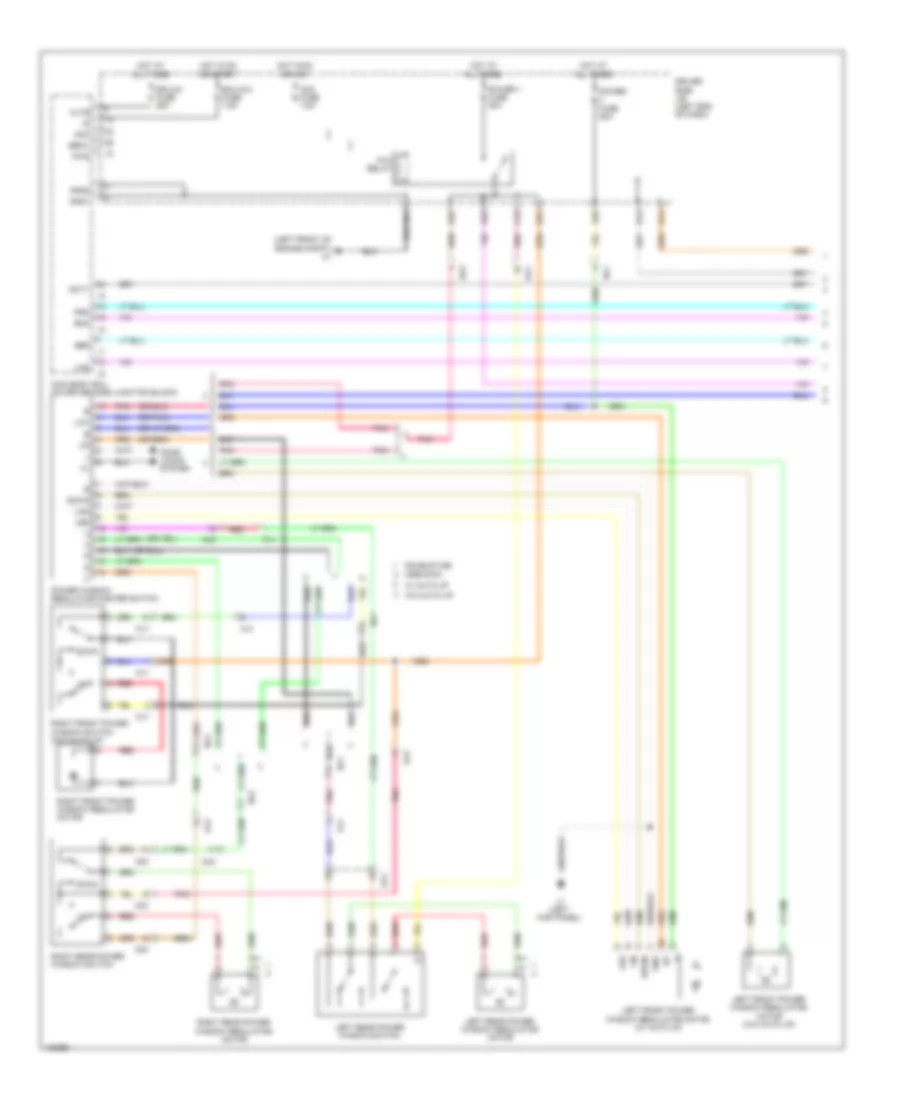 https://portal-diagnostov.com/license.html
Automotive Electricians Portal FZCO
Automotive Electricians Portal FZCO
https://portal-diagnostov.com/license.html
https://portal-diagnostov.com/license.html
Automotive Electricians Portal FZCO
Automotive Electricians Portal FZCO
List of elements for Power Windows Wiring Diagram, Except Regular Cab (1 of 2) for Toyota Tundra SR 2014:
- (left front of engine compt) a1
- (or pnk)
- Acc
- Acc fuse 7.5a
- Altb
- B13
- B21
- Becu
- Bzr
- C19
- Crewmax
- D14
- D31
- D32
- D33
- D35
- Dcty
- Door locks system
- Double cab
- Down
- Dr/lck fuse 25a
- Driver side j/b (left end of dash)
- Ecu-ig 2 fuse 7.5a
- Gnd
- Gnd1
- Gnd2
- Hot at all times
- Hot in on or acc
- Hot in on or start
- J1 (left kick panel)
- Led
- Left front power window regulator motor (w/ auto up)
- Left front power window regulator motor (w/o auto up)
- Left rear power window regulator motor
- Left rear power window switch
- Lin
- Lin1
- Lin2
- Main body ecu (on driver side junction block)
- Mj1
- Nj1
- Nj2
- Nj3
- Op1
- Oq1
- P/w relay
- Pj1
- Pnk
- Power 1 fuse 30a
- Power fuse 20a
- Power window regulator master switch
- Prg
- Pws
- Qj2
- Rda
- Red
- Right front power window regulator motor
- Right front power window switch (w/o auto up)
- Right rear power window regulator motor
- Right rear power window switch
- W/ auto up
- W/o auto up
Power Windows Wiring Diagram, Except Regular Cab (2 of 2) for Toyota Tundra SR 2014
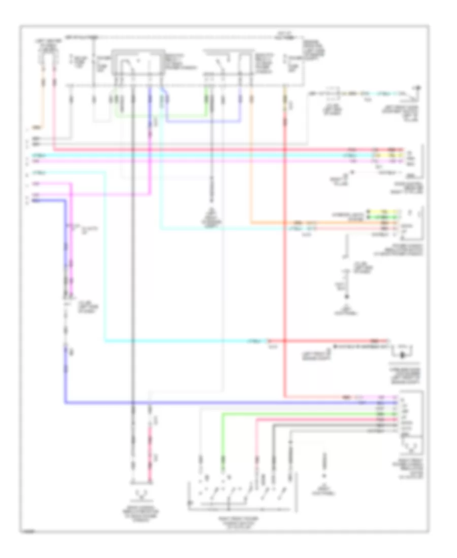 https://portal-diagnostov.com/license.html
Automotive Electricians Portal FZCO
Automotive Electricians Portal FZCO
https://portal-diagnostov.com/license.html
https://portal-diagnostov.com/license.html
Automotive Electricians Portal FZCO
Automotive Electricians Portal FZCO
List of elements for Power Windows Wiring Diagram, Except Regular Cab (2 of 2) for Toyota Tundra SR 2014:
- (left center of dash) j/c j70
- A2 (left front of engine compt)
- Aj10
- Aj11
- Auto
- Back p/w relay 1 (w/ back power window)
- Back p/w relay 2 (w/ back power window)
- Back window regulator motor (w/ back power window)
- Door control receiver (right "c" pillar)
- Down
- Ecu-b1 fuse 7.5a
- Engine room r/b (left side of engine compt)
- Gnd
- Hot at all times
- Interior lights system
- J/c j60 (left end of dash)
- J/c j64 (left end of dash)
- J/c j65 (left side of dash)
- J1 (left kick panel)
- J3 (right kick panel)
- Led
- Left front door courtesy switch (left "b" pillar)
- Lin
- Mj1
- Mj2
- Nj3
- Pj2
- Pnk
- Power fuse 25a
- Power fuse 30a
- Power window regulator switch (w/ back power window)
- Prg
- Q2 (right "c" pillar)
- Qj1
- Qj2
- Rda
- Red
- Right front power window regulator motor (w/ auto up)
- Right front power window switch (w/ auto up)
- W/ auto up
- Wireless door lock buzzer (left front of engine compt)
Power Windows Wiring Diagram, Regular Cab (1 of 2) for Toyota Tundra SR 2014
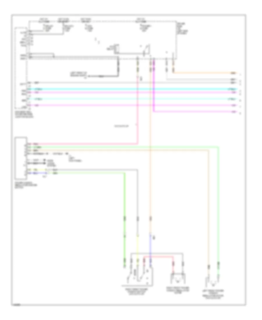 https://portal-diagnostov.com/license.html
Automotive Electricians Portal FZCO
Automotive Electricians Portal FZCO
https://portal-diagnostov.com/license.html
https://portal-diagnostov.com/license.html
Automotive Electricians Portal FZCO
Automotive Electricians Portal FZCO
List of elements for Power Windows Wiring Diagram, Regular Cab (1 of 2) for Toyota Tundra SR 2014:
- (left front of engine compt) a1
- Acc
- Acc fuse 7.5a
- Altb
- B13
- B21
- Becu
- Bzr
- D14
- D31
- D32
- D33
- Dcty
- Door locks system
- Down
- Dr/lck fuse 25a
- Driver side j/b (left end of dash)
- Ecu-ig 2 fuse 7.5a
- Gnd1
- Gnd2
- Hot at all times
- Hot in on or acc
- Hot in on or start
- J1 (left kick panel)
- Left front power window regulator motor (w/o auto up)
- Lin2
- Main body ecu (on driver side junction block)
- Mj1
- Nj1
- Nj3
- P/w relay
- Pnk
- Power 1 fuse 30a
- Power window regulator master switch
- Prg
- Pws
- Rda
- Red
- Right front power window regulator motor
- Right front power window switch (w/o auto up)
- W/o auto up
Power Windows Wiring Diagram, Regular Cab (2 of 2) for Toyota Tundra SR 2014
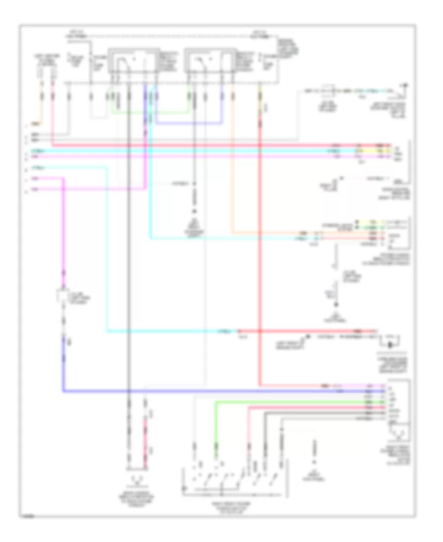 https://portal-diagnostov.com/license.html
Automotive Electricians Portal FZCO
Automotive Electricians Portal FZCO
https://portal-diagnostov.com/license.html
https://portal-diagnostov.com/license.html
Automotive Electricians Portal FZCO
Automotive Electricians Portal FZCO
List of elements for Power Windows Wiring Diagram, Regular Cab (2 of 2) for Toyota Tundra SR 2014:
- (left center of dash) j/c j70
- A2 (left front of engine compt)
- Aj10
- Aj11
- Auto
- Back p/w relay 1 (w/ back power window)
- Back p/w relay 2 (w/ back power window)
- Back window regulator motor (w/ back power window)
- Door control receiver (right "b" pillar)
- Down
- Ecu-b1 fuse 7.5a
- Engine room r/b (left side of engine compt)
- Gnd
- Hot at all times
- Interior lights system
- J/c j60 (left end of dash)
- J/c j64 (left end of dash)
- J/c j65 (left side of dash)
- J1 (left kick panel)
- J3 (right kick panel)
- Led
- Left front door courtesy switch (left "b" pillar)
- Lin
- Mj1
- Mj2
- Pj2
- Pnk
- Power fuse 25a
- Power fuse 30a
- Power window regulator switch (w/ back power window)
- Prg
- Q2 (right "b" pillar)
- Qj1
- Qj2
- Rda
- Red
- Right front power window regulator motor (w/ auto up)
- Right front power window switch (w/ auto up)
- Wireless door lock buzzer (left front of engine compt)
RADIO
Radio Wiring Diagram, with Built-in Amplifier (1 of 3) for Toyota Tundra SR 2014
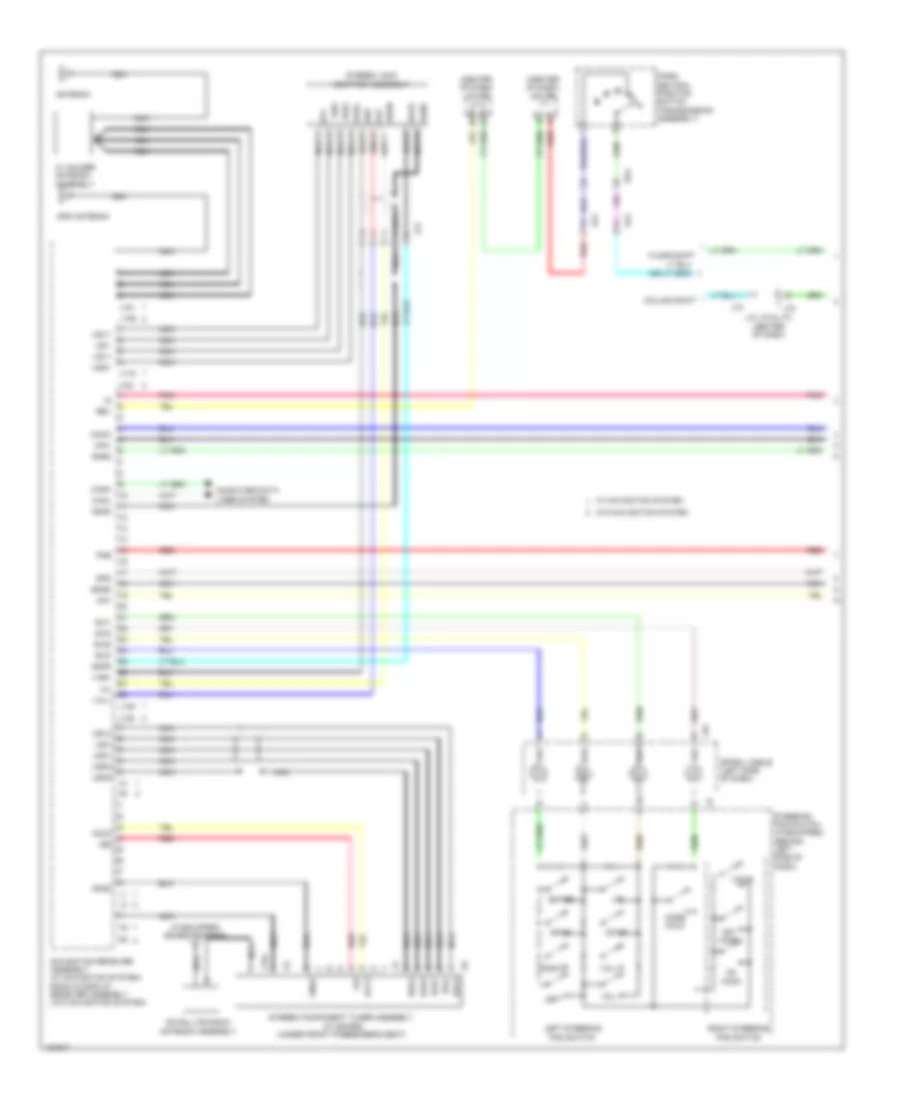 https://portal-diagnostov.com/license.html
Automotive Electricians Portal FZCO
Automotive Electricians Portal FZCO
https://portal-diagnostov.com/license.html
https://portal-diagnostov.com/license.html
Automotive Electricians Portal FZCO
Automotive Electricians Portal FZCO
List of elements for Radio Wiring Diagram, with Built-in Amplifier (1 of 3) for Toyota Tundra SR 2014:
- (center of dash) j/c j65
- (center of dash) j/c j66
- (if equipped) sdars antenna
- +b2
- Acc2
- Adpg
- Agnd
- Aj2
- Aj4
- Alo
- Antenna
- Aro
- Asgn
- Au1
- Au2
- Au3
- Auxo
- Back
- Canh
- Canl
- Column shift
- Computer data lines system
- Da4
- Down
- Eau
- Enter
- Floor shift
- Gnd2
- Gps antenna
- J/c j72 & j73 (center of dash)
- J116
- J122
- J135
- J139
- J151
- J154
- J155
- J45
- J72
- J73
- Jj2
- Left
- Left steering pad switch
- Macc
- Min+
- Min-
- Mode hold
- Navigation receiver assembly (w/ navigation system) radio & display receiver assembly (w/o navigation system)
- Nca
- Off hook
- On hook
- Park/ neutral position switch (transmission assembly)
- Pkb
- Pnk
- Red
- Rev
- Right
- Right steering pad switch
- Satellite radio antenna assembly
- Sgnd
- Sns2
- Spd
- Spiral cable (left side of dash)
- Steering pad switch (if equipped) (behind left side of dash)
- Stereo component tuner assembly (w/ sdars) (under front passenger's seat)
- Stereo jack adapter assembly
- Sw1
- Sw2
- Sw3
- Swg
- Udo+
- Udo-
- Ugd1
- Ugd4
- Ujsg
- Up1
- Us1+
- Us1-
- Us4+
- Us4-
- Usg4
- Usv1
- Usv4
- Va-
- Val+
- Var+
- Voice
- Vol+
- Vol-
- W/ holder antenna assembly
- W/ navigation system
- W/o navigation system
Radio Wiring Diagram, with Built-in Amplifier (2 of 3) for Toyota Tundra SR 2014
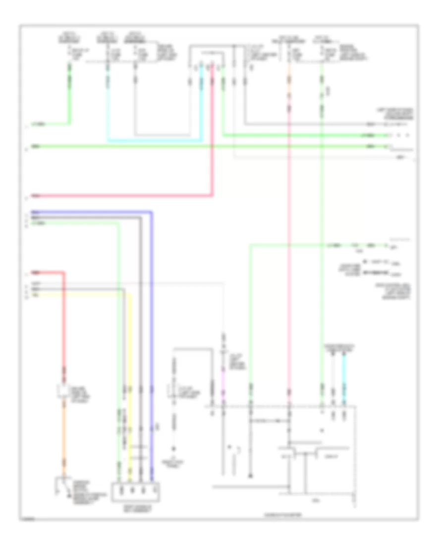 https://portal-diagnostov.com/license.html
Automotive Electricians Portal FZCO
Automotive Electricians Portal FZCO
https://portal-diagnostov.com/license.html
https://portal-diagnostov.com/license.html
Automotive Electricians Portal FZCO
Automotive Electricians Portal FZCO
List of elements for Radio Wiring Diagram, with Built-in Amplifier (2 of 3) for Toyota Tundra SR 2014:
- (left side of dash) (column shift) diode (ignition)
- 5v ic
- Acc
- Acc fuse 7.5a
- Aj10
- Aj9
- B11
- Bk/up lp fuse 10a
- Can i/f
- Canh
- Canl
- Combination meter
- Computer data lines system
- Cpu
- D55
- D65
- Driver side j/b (left end of dash)
- Engine room r/b (left side of engine compt)
- Hot at all times
- Hot w/ acc relay energized
- Hot w/ ig1 relay 1 energized
- Hot w/ ig1 relay 2 energized
- Hot w/ ig2 relay energized
- Ig+
- J/c j61 (left side of dash)
- J/c j70 & j71 (left center of dash)
- J/c j70 (left center of dash)
- J3 (right kick panel)
- J70
- J71
- Jw1
- Lh ig fuse 7.5a
- Met fuse 7.5a
- Met-b fuse 5a
- Mi1+
- Mic-
- Nca
- Parking brake switch (base of parking brake lever assembly)
- Pnk
- Red
- Roof console box assembly
- Sgnd
- Skid control ecu w/ actuator (left side of engine compt)
- Sp1
Radio Wiring Diagram, with Built-in Amplifier (3 of 3) for Toyota Tundra SR 2014
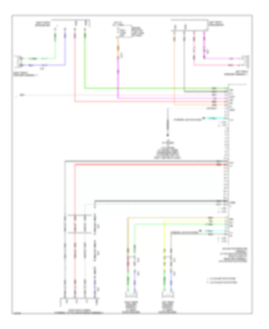 https://portal-diagnostov.com/license.html
Automotive Electricians Portal FZCO
Automotive Electricians Portal FZCO
https://portal-diagnostov.com/license.html
https://portal-diagnostov.com/license.html
Automotive Electricians Portal FZCO
Automotive Electricians Portal FZCO
List of elements for Radio Wiring Diagram, with Built-in Amplifier (3 of 3) for Toyota Tundra SR 2014:
- +b1
- Acc1
- Aj11
- Aj5
- Ca+
- Cb+
- Cgnd
- Cv+
- Cv-
- Engine room r/b (left side of dash)
- Fl+
- Fl-
- Fr+
- Fr-
- Gnd1
- Hot at all times
- Ill+
- Ill-
- Interior lights system
- J133
- J134
- J136
- J137
- J138
- J140
- J6 (w/ sdars) j5 (w/o sdars) (w/ sdars: under passenger's seat) (w/o sdars: bottom right center of dash)
- Left front speaker assembly 1
- Left front speaker set
- Left rear speaker assembly (w/ rear door speaker)
- Mj2
- Navigation receiver assembly (w/ navigation system) radio & display receiver assembly (w/o navigation system)
- Nca
- Nj3
- Op1
- Oq1
- Pj1
- Pnk
- Qj2
- Ra1
- Rad 1 fuse 20a
- Red
- Right front speaker assembly 1
- Right front speaker set
- Right rear speaker assembly (w/ rear door speaker)
- Rl+
- Rl-
- Rr+
- Rr-
- Television camera (integral to tail gate handle assembly)
- Twl+
- Twl-
- Twr+
- Twr-
- W/ navigation system
- W/o navigation system
- Xr1
Radio Wiring Diagram, with Separate Amplifier & JBL (1 of 4) for Toyota Tundra SR 2014
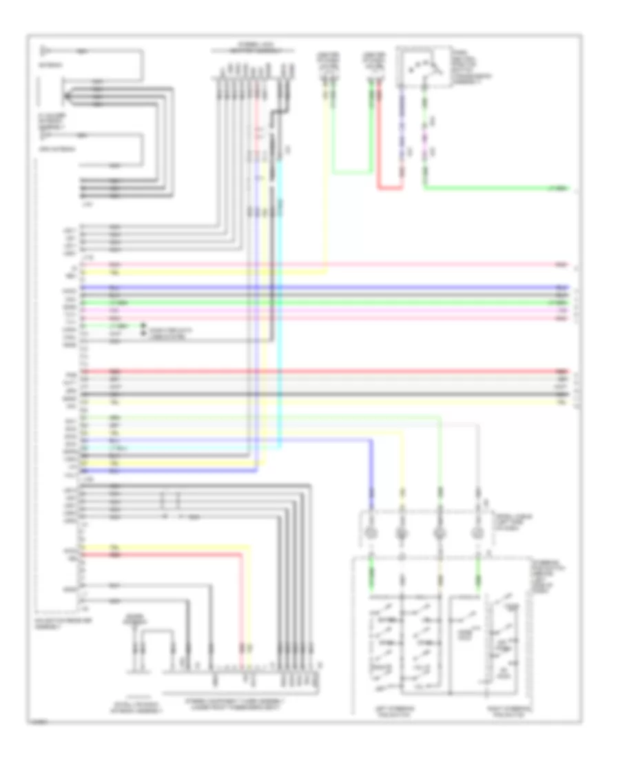 https://portal-diagnostov.com/license.html
Automotive Electricians Portal FZCO
Automotive Electricians Portal FZCO
https://portal-diagnostov.com/license.html
https://portal-diagnostov.com/license.html
Automotive Electricians Portal FZCO
Automotive Electricians Portal FZCO
List of elements for Radio Wiring Diagram, with Separate Amplifier & JBL (1 of 4) for Toyota Tundra SR 2014:
- (center of dash) j/c j65
- (center of dash) j/c j66
- +b2
- Acc2
- Adpg
- Agnd
- Aj2
- Aj4
- Alo
- Antenna
- Aro
- Asgn
- Au1
- Au2
- Au3
- Auxo
- Back
- Canh
- Canl
- Computer data lines system
- Da4
- Down
- Eau
- Enter
- Gnd2
- Gps antenna
- J116
- J135
- J151
- J154
- J45
- Jj2
- Left
- Left steering pad switch
- Macc
- Min+
- Min-
- Mode hold
- Mut1
- Navigation receiver assembly
- Nca
- Off hook
- On hook
- Park/ neutral position switch (transmission assembly)
- Pkb
- Pnk
- Red
- Rev
- Right
- Right steering pad switch
- Satellite radio antenna assembly
- Sdars antenna
- Sgnd
- Sns2
- Spd
- Spiral cable (left side of dash)
- Steering pad switch (behind left side of dash)
- Stereo component tuner assembly (under front passenger's seat)
- Stereo jack adapter assembly
- Sw1
- Sw2
- Sw3
- Swg
- Tx1+
- Tx1-
- Udo+
- Udo-
- Ugd1
- Ugd4
- Ujsg
- Up1
- Us1+
- Us1-
- Us4+
- Us4-
- Usg4
- Usv1
- Usv4
- Va-
- Val+
- Var+
- Voice
- Vol+
- Vol-
- W/ holder antenna assembly
Radio Wiring Diagram, with Separate Amplifier & JBL (2 of 4) for Toyota Tundra SR 2014
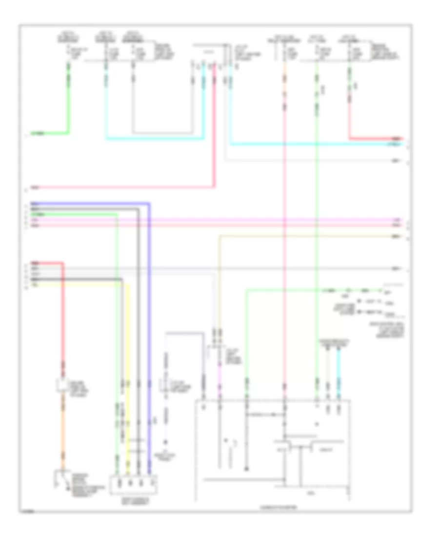 https://portal-diagnostov.com/license.html
Automotive Electricians Portal FZCO
Automotive Electricians Portal FZCO
https://portal-diagnostov.com/license.html
https://portal-diagnostov.com/license.html
Automotive Electricians Portal FZCO
Automotive Electricians Portal FZCO
List of elements for Radio Wiring Diagram, with Separate Amplifier & JBL (2 of 4) for Toyota Tundra SR 2014:
- 5v ic
- Acc
- Acc fuse 7.5a
- Ag9
- Aj10
- Aj9
- Amp fuse 30a
- B11
- Bk/up lp fuse 10a
- Can i/f
- Canh
- Canl
- Combination meter
- Computer data lines system
- Cpu
- D55
- D65
- Driver side j/b (left end of dash)
- Engine room r/b (left side of engine compt)
- Hot at all times
- Hot w/ acc relay energized
- Hot w/ ig1 relay 1 energized
- Hot w/ ig1 relay 2 energized
- Hot w/ ig2 relay energized
- Ig+
- J/c j61 (left side of dash)
- J/c j70 & j71 (left center of dash)
- J/c j70 (left center of dash)
- J3 (right kick panel)
- J70
- J71
- Jw1
- Lh ig fuse 7.5a
- Met fuse 7.5a
- Met-b fuse 5a
- Mi1+
- Mic-
- Nca
- Parking brake switch (base of parking brake lever assembly)
- Pnk
- Red
- Roof console box assembly
- Sgnd
- Skid control ecu w/ actuator (left side of engine compt)
- Sp1
Radio Wiring Diagram, with Separate Amplifier & JBL (3 of 4) for Toyota Tundra SR 2014
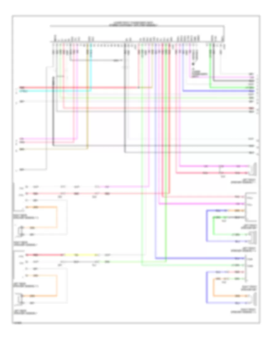 https://portal-diagnostov.com/license.html
Automotive Electricians Portal FZCO
Automotive Electricians Portal FZCO
https://portal-diagnostov.com/license.html
https://portal-diagnostov.com/license.html
Automotive Electricians Portal FZCO
Automotive Electricians Portal FZCO
List of elements for Radio Wiring Diagram, with Separate Amplifier & JBL (3 of 4) for Toyota Tundra SR 2014:
- (under front passenger's seat) stereo component amplifier assembly
- +b2
- +tw
- -tw
- Acc
- Ctr+
- Ctr-
- Fl+
- Fl-
- Fr+
- Fr-
- Gnd
- Gnd2
- Ii1+
- Ii1-
- J141
- J142
- J143
- J6 (under passenger's seat)
- Left front speaker assembly 1
- Left front speaker assembly 2
- Left front speaker set
- Left rear speaker assembly
- Left rear speaker assembly 2
- Mj2
- Mute
- Nca
- Nj3
- Op1
- Oq1
- Pj1
- Pnk
- Qj2
- Red
- Right front speaker assembly 2
- Right front speaker set
- Right rear speaker assembly
- Right rear speaker assembly 2
- Rl+
- Rl-
- Rr+
- Rr-
- Sld
- Spd
- Twl+
- Twl-
- Twr+
- Twr-
- Tx+
- Tx-
- Wf1+
- Wf1-
- Wfl+
- Wfl-
- Wfr+
- Wfr-
Radio Wiring Diagram, with Separate Amplifier & JBL (4 of 4) for Toyota Tundra SR 2014
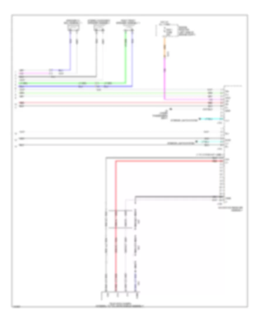 https://portal-diagnostov.com/license.html
Automotive Electricians Portal FZCO
Automotive Electricians Portal FZCO
https://portal-diagnostov.com/license.html
https://portal-diagnostov.com/license.html
Automotive Electricians Portal FZCO
Automotive Electricians Portal FZCO
List of elements for Radio Wiring Diagram, with Separate Amplifier & JBL (4 of 4) for Toyota Tundra SR 2014:
- (1 to 10 pins not used)
- +b1
- Acc1
- Aj11
- Aj5
- Ca+
- Cb+
- Cgnd
- Cv+
- Cv-
- Engine room r/b (left side of engine compt)
- Fl+
- Fl-
- Fr+
- Fr-
- Gnd1
- Hot at all times
- Ill+
- Ill-
- Interior lights system
- J133
- J134
- J136
- J6 (under passenger's seat)
- Mj2
- Navigation receiver assembly
- Nca
- Pj1
- Ra1
- Rad 1 fuse 20a
- Red
- Right front speaker assembly 1
- Rl+
- Rl-
- Sld2
- Speaker w/ box assembly 1
- Stereo component speaker assembly
- Television camera (integral to tail gate handle assembly)
- Xr1
Radio Wiring Diagram, with Separate Amplifier & without JBL (1 of 4) for Toyota Tundra SR 2014
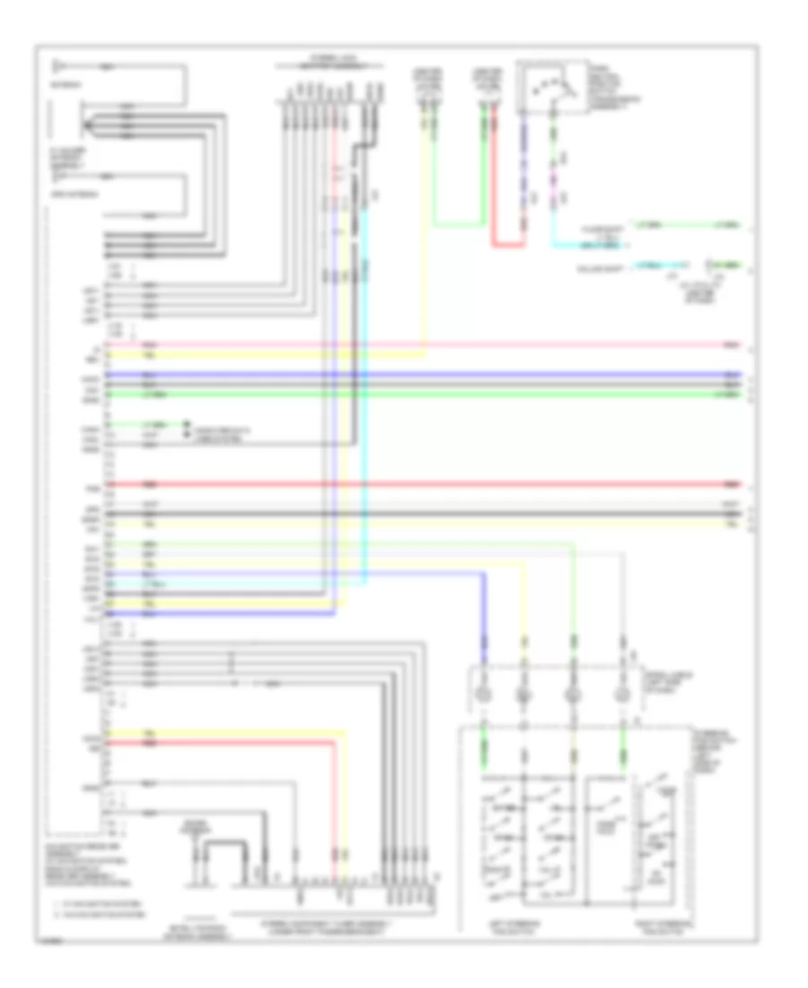 https://portal-diagnostov.com/license.html
Automotive Electricians Portal FZCO
Automotive Electricians Portal FZCO
https://portal-diagnostov.com/license.html
https://portal-diagnostov.com/license.html
Automotive Electricians Portal FZCO
Automotive Electricians Portal FZCO
List of elements for Radio Wiring Diagram, with Separate Amplifier & without JBL (1 of 4) for Toyota Tundra SR 2014:
- (center of dash) j/c j65
- (center of dash) j/c j66
- +b2
- Acc2
- Adpg
- Agnd
- Aj2
- Aj4
- Alo
- Antenna
- Aro
- Asgn
- Au1
- Au2
- Au3
- Auxo
- Back
- Canh
- Canl
- Column shift
- Computer data lines system
- Da4
- Down
- Eau
- Enter
- Floor shift
- Gnd2
- Gps antenna
- J/c j72 & j73 (center of dash)
- J116
- J122
- J135
- J139
- J151
- J154
- J155
- J45
- J72
- J73
- Jj2
- Left
- Left steering pad switch
- Macc
- Min+
- Min-
- Mode hold
- Navigation receiver assembly (w/ navigation system) radio & display receiver assembly (w/o navigation system)
- Nca
- Off hook
- On hook
- Park/ neutral position switch (transmission assembly)
- Pkb
- Pnk
- Red
- Rev
- Right
- Right steering pad switch
- Satellite radio antenna assembly
- Sdars antenna
- Sgnd
- Sns2
- Spd
- Spiral cable (left side of dash)
- Steering pad switch (behind left side of dash)
- Stereo component tuner assembly (under front passenger's seat)
- Stereo jack adapter assembly
- Sw1
- Sw2
- Sw3
- Swg
- Udo+
- Udo-
- Ugd4
- Ujsg
- Up1
- Us1+
- Us1-
- Us4+
- Us4-
- Usd1
- Usg4
- Usv1
- Usv4
- Va-
- Val+
- Var+
- Voice
- Vol+
- Vol-
- W/ holder antenna assembly
- W/ navigation system
- W/o navigation system
Radio Wiring Diagram, with Separate Amplifier & without JBL (2 of 4) for Toyota Tundra SR 2014
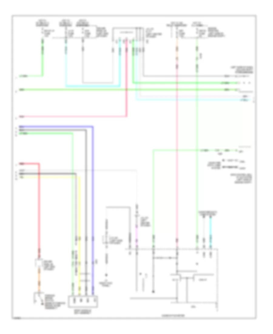 https://portal-diagnostov.com/license.html
Automotive Electricians Portal FZCO
Automotive Electricians Portal FZCO
https://portal-diagnostov.com/license.html
https://portal-diagnostov.com/license.html
Automotive Electricians Portal FZCO
Automotive Electricians Portal FZCO
List of elements for Radio Wiring Diagram, with Separate Amplifier & without JBL (2 of 4) for Toyota Tundra SR 2014:
- (left side of dash) (column shift) diode (ignition)
- 5v ic
- Acc
- Acc fuse 7.5a
- Ag9
- Aj10
- B11
- Bk/up lp fuse 10a
- Can i/f
- Canh
- Canl
- Combination meter
- Computer data lines system
- Cpu
- D55
- D65
- Driver side j/b (left end of dash)
- Engine room r/b (left side of engine compt)
- Hot at all times
- Hot w/ acc relay energized
- Hot w/ ig1 relay 1 energized
- Hot w/ ig1 relay 2 energized
- Hot w/ ig2 relay energized
- Ig+
- J/c j61 (left side of dash)
- J/c j70 & j71 (left center of dash)
- J/c j70 (left center of dash)
- J3 (right kick panel)
- J70
- J71
- Jw1
- Lh ig fuse 7.5a
- Met fuse 7.5a
- Met-b fuse 5a
- Mi1+
- Mic-
- Nca
- Parking brake switch (base of parking brake lever assembly)
- Pnk
- Red
- Roof console box assembly
- Sgnd
- Skid control ecu w/ actuator (left side of engine compt)
- Sp1
Radio Wiring Diagram, with Separate Amplifier & without JBL (3 of 4) for Toyota Tundra SR 2014
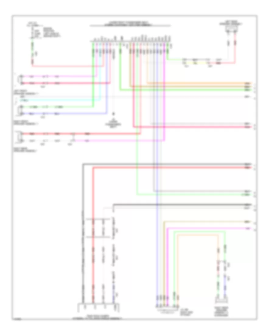 https://portal-diagnostov.com/license.html
Automotive Electricians Portal FZCO
Automotive Electricians Portal FZCO
https://portal-diagnostov.com/license.html
https://portal-diagnostov.com/license.html
Automotive Electricians Portal FZCO
Automotive Electricians Portal FZCO
List of elements for Radio Wiring Diagram, with Separate Amplifier & without JBL (3 of 4) for Toyota Tundra SR 2014:
- (under front passenger's seat) stereo component amplifier assembly
- Acc
- Aj5
- Aj9
- Amp
- Amp fuse 30a
- Cb+
- Cgnd
- Cv+
- Cv-
- Engine room r/b (left side of engine compt)
- Fl+
- Fl-
- Fr+
- Fr-
- Gnd
- Hot at all times
- J/c j69 (right end of dash)
- J144
- J145
- J6 (under passenger's seat)
- Left front speaker assembly 1
- Left rear speaker assembly
- Mj2
- Nca
- Nj3
- Op1
- Oq1
- Pj1
- Pnk
- Qj2
- Ra1
- Red
- Right front speaker assembly 1
- Right rear speaker assembly
- Right rear speaker assembly 2 (9 speaker)
- Rl+
- Rl-
- Rr+
- Rr-
- Television camera (integral to tail gate handle assembly)
- Wfl+
- Wfl-
- Wfr+
- Wfr-
- Xr1
Radio Wiring Diagram, with Separate Amplifier & without JBL (4 of 4) for Toyota Tundra SR 2014
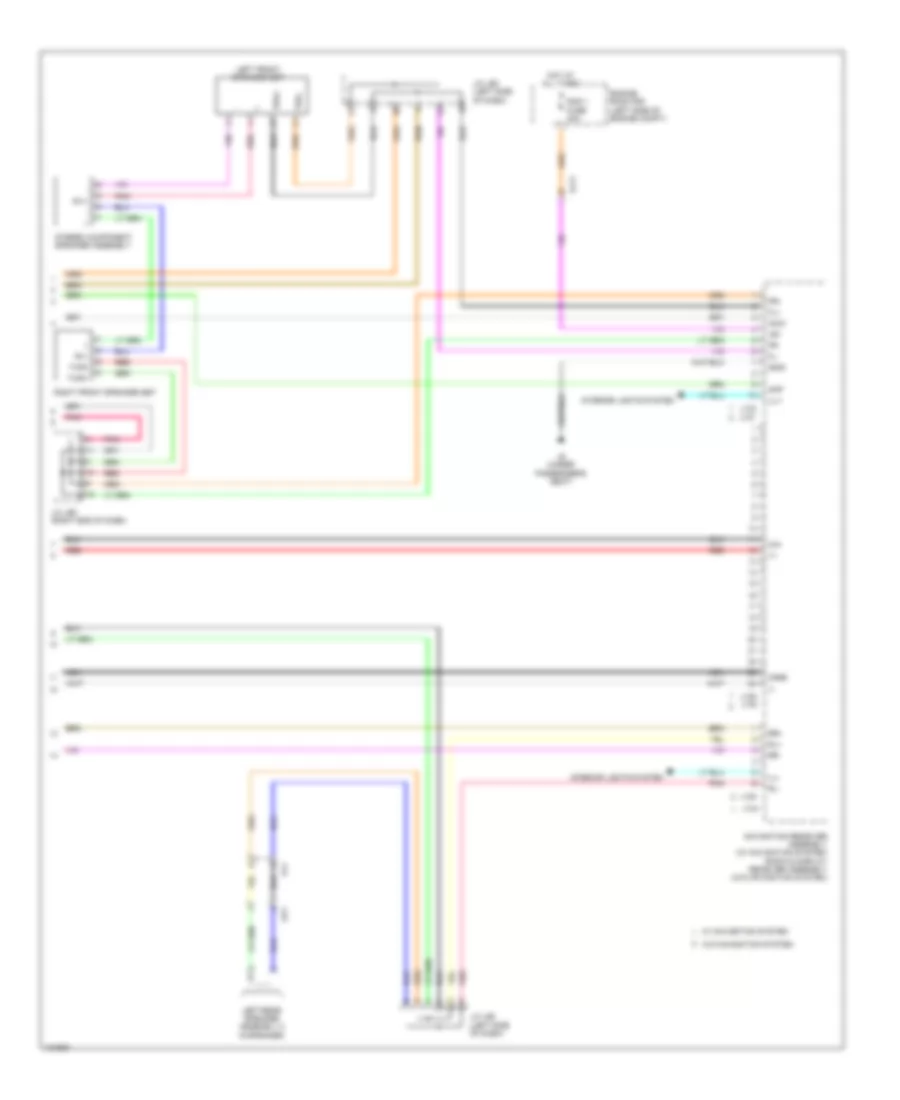 https://portal-diagnostov.com/license.html
Automotive Electricians Portal FZCO
Automotive Electricians Portal FZCO
https://portal-diagnostov.com/license.html
https://portal-diagnostov.com/license.html
Automotive Electricians Portal FZCO
Automotive Electricians Portal FZCO
List of elements for Radio Wiring Diagram, with Separate Amplifier & without JBL (4 of 4) for Toyota Tundra SR 2014:
- +b1
- Acc1
- Aj11
- Amp
- Ca+
- Cgnd
- Engine room r/b (left side of engine compt)
- Fl+
- Fl-
- Fr+
- Fr-
- Gnd1
- Hot at all times
- Ill+
- Ill-
- Interior lights system
- J/c j68 (left side of dash)
- J/c j69 (right end of dash)
- J133
- J134
- J136 j140
- J137
- J138
- J6 (under passenger's seat)
- Left front speaker set
- Left rear speaker assembly 2 (9 speaker)
- Navigation receiver assembly (w/ navigation system) radio & display receiver assembly (w/o navigation system)
- Nca
- Op1
- Pj1
- Pnk
- Rad 1 fuse 20a
- Red
- Ri1+
- Ri1-
- Right front speaker set
- Rl+
- Rl-
- Rr+
- Rr-
- Stereo component speaker assembly
- Twl+
- Twl-
- Twr+
- Twr-
- W/ navigation system
- W/o navigation system
SHIFT INTERLOCK
Shift Interlock Wiring Diagram, with Column Shift for Toyota Tundra SR 2014
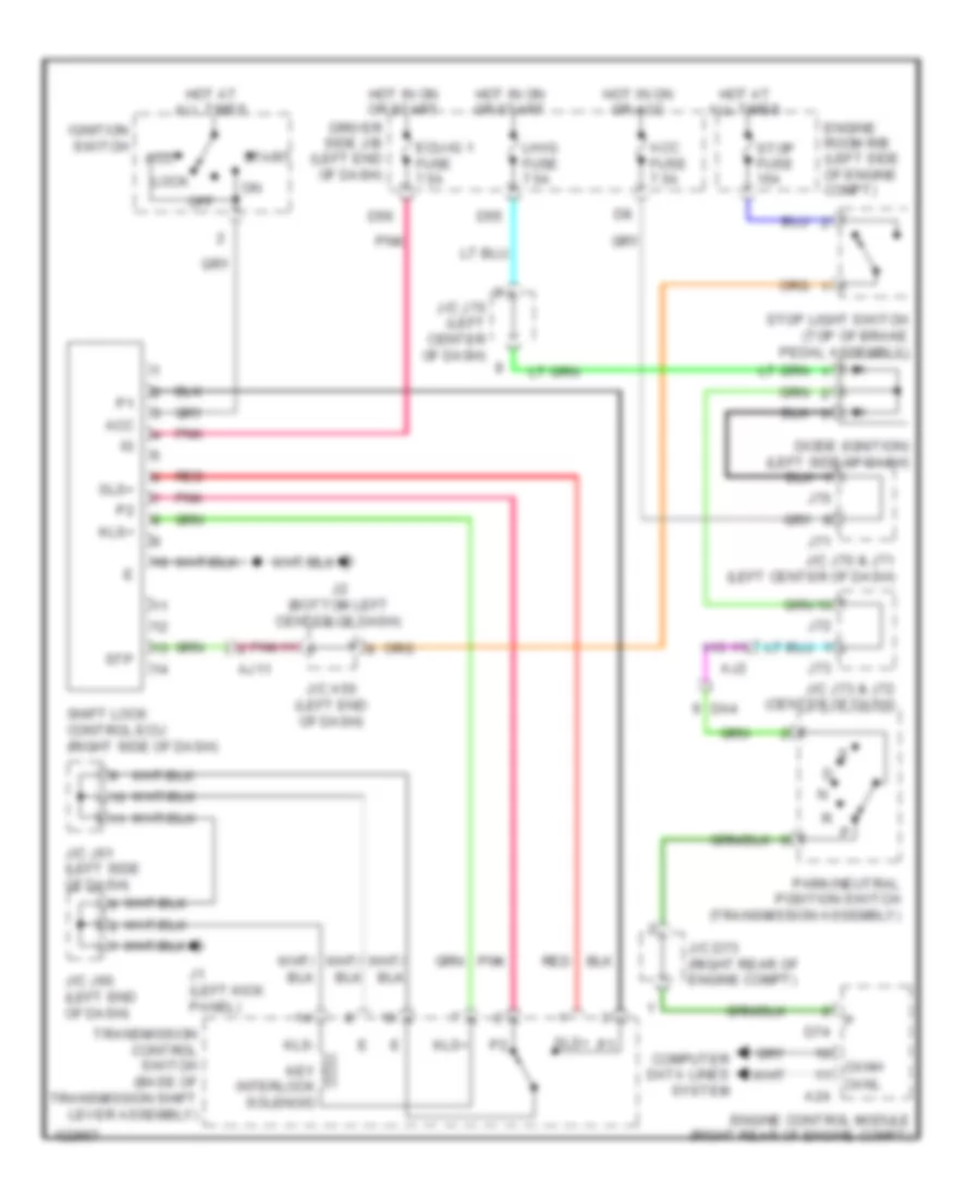 https://portal-diagnostov.com/license.html
Automotive Electricians Portal FZCO
Automotive Electricians Portal FZCO
https://portal-diagnostov.com/license.html
https://portal-diagnostov.com/license.html
Automotive Electricians Portal FZCO
Automotive Electricians Portal FZCO
List of elements for Shift Interlock Wiring Diagram, with Column Shift for Toyota Tundra SR 2014:
- A24
- Acc
- Acc fuse 7.5a
- Aj11
- Aj2
- Canh
- Canl
- Computer data lines system
- D55
- D56
- D74
- Da4
- Diode (ignition) (left side of dash)
- Driver side j/b (left end of dash)
- Ecu-ig 1 fuse 7.5a
- Engine control module (right rear of engine compt)
- Engine room r/b (left side of engine compt)
- Hot at all times
- Hot in on or acc
- Hot in on or start
- Ignition switch
- J/c a50 (left end of dash)
- J/c d73 (right rear of engine compt)
- J/c j60 (left end of dash)
- J/c j61 (left side of dash)
- J/c j70 & j71 (left center of dash)
- J/c j70 (left center of dash)
- J/c j73 & j72 (center of dash)
- J1 (left kick panel)
- J2 (bottom left center of dash)
- J70
- J71
- J72
- J73
- Key interlock solenoid
- Kls+
- Kls-
- Lh-ig fuse 7.5a
- Lock
- Off
- Park/neutral position switch (transmission assembly)
- Pnk
- Red
- Shift lock control ecu (right side of dash)
- Sls+
- Start
- Stop fuse 15a
- Stop light switch (top of brake pedal assembly)
- Stp
- Transmission control switch (base of transmission shift lever assembly)
Shift Interlock Wiring Diagram, with Floor Shift for Toyota Tundra SR 2014
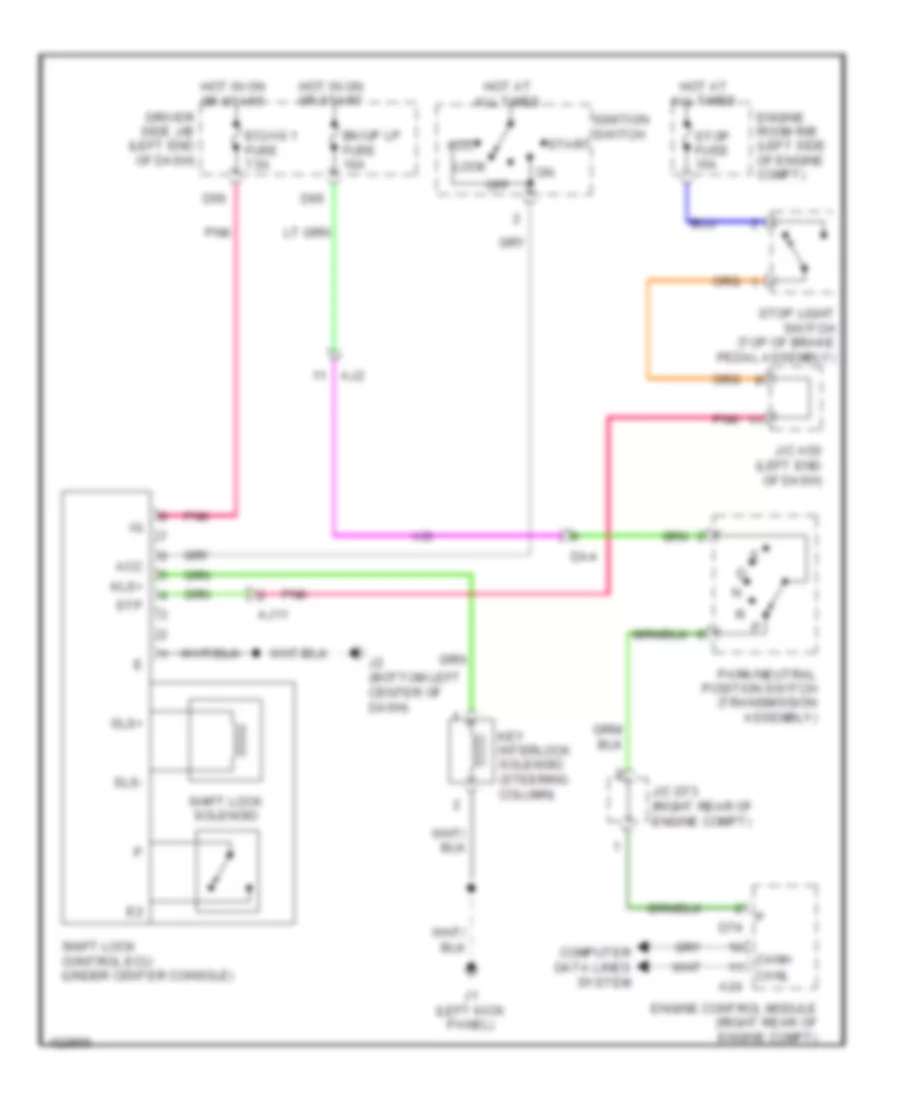 https://portal-diagnostov.com/license.html
Automotive Electricians Portal FZCO
Automotive Electricians Portal FZCO
https://portal-diagnostov.com/license.html
https://portal-diagnostov.com/license.html
Automotive Electricians Portal FZCO
Automotive Electricians Portal FZCO
List of elements for Shift Interlock Wiring Diagram, with Floor Shift for Toyota Tundra SR 2014:
- (steering column)
- A24
- Acc
- Aj11
- Aj2
- Bk/up lp fuse 10a
- Canh
- Canl
- Computer data lines system
- D56
- D65
- D74
- Da4
- Driver side j/b (left end of dash)
- Ecu-ig 1 fuse 7.5a
- Engine control module (right rear of engine compt)
- Engine room r/b (left side of engine compt)
- Hot at all times
- Hot in on or start
- Ignition switch
- J/c a50 (left end of dash)
- J/c d73 (right rear of engine compt)
- J1 (left kick panel)
- J2 (bottom left center of dash)
- Key interlock solenoid
- Kls+
- Lock
- Off
- Park/neutral position switch (transmission assembly)
- Pnk
- Shift lock control ecu (under center console)
- Shift lock solenoid
- Sls+
- Sls-
- Start
- Stop fuse 15a
- Stop light switch (top of brake pedal assembly)
- Stp
STARTING/CHARGING
Charging Wiring Diagram for Toyota Tundra SR 2014
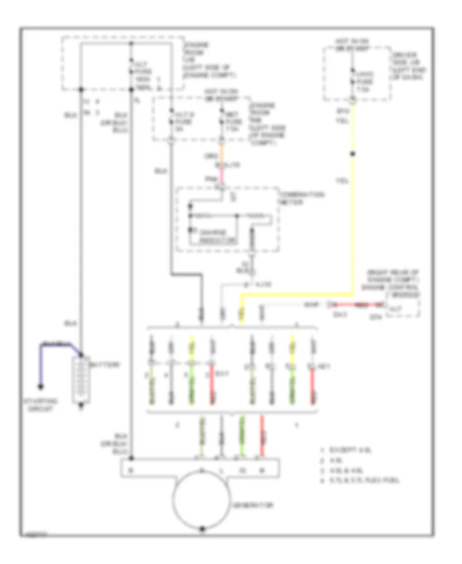 https://portal-diagnostov.com/license.html
Automotive Electricians Portal FZCO
Automotive Electricians Portal FZCO
https://portal-diagnostov.com/license.html
https://portal-diagnostov.com/license.html
Automotive Electricians Portal FZCO
Automotive Electricians Portal FZCO
List of elements for Charging Wiring Diagram for Toyota Tundra SR 2014:
- (right rear of engine compt) engine control module
- 4.0l
- 4.0l & 4.6l
- 5.7l & 5.7l flex fuel
- Ae1
- Aj10
- Alt
- Alt fuse 180a 140a
- Alt-s fuse 5a
- B10
- Battery
- Charge indicator
- Chg
- Combination meter
- D74
- Da3
- Driver side j/b (left end of dash)
- Ea1
- Engine room j/b (left side of engine compt)
- Engine room r/b (left side of engine compt)
- Except 4.0l
- Generator
- Hot in on or start
- Igt
- Lh-ig fuse 7.5a
- Met fuse 7.5a
- Pnk
- Red
- Starting circuit
Starting Wiring Diagram for Toyota Tundra SR 2014
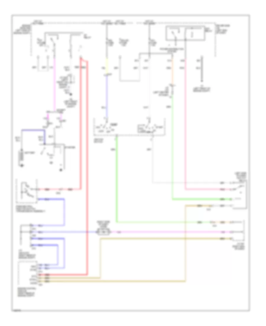 https://portal-diagnostov.com/license.html
Automotive Electricians Portal FZCO
Automotive Electricians Portal FZCO
https://portal-diagnostov.com/license.html
https://portal-diagnostov.com/license.html
Automotive Electricians Portal FZCO
Automotive Electricians Portal FZCO
List of elements for Starting Wiring Diagram for Toyota Tundra SR 2014:
- (left side of dash) acc cut relay
- (right side of dash) diode (starting)
- 4.0l
- A1 (left front of engine compt)
- A2 (left front of engine compt)
- A24
- A45
- Acc
- Acc lock
- Acc relay
- Accr
- Ae1
- Aj3
- Aj9
- Am1 fuse 7.5a
- Am2 fuse 7.5a
- B13
- B21
- Battery
- D14
- D45
- D47
- D73
- D74
- Da2
- Driver side j/b (left end of dash)
- Ea1
- Ecu-b1 fuse 7.5a
- Engine control module (right rear of engine compt)
- Engine room r/b (left side of engine compt)
- Except 4.0l
- Hot at all times
- Ignition switch
- J/c a44 (left front of engine compt)
- J/c a45 & d73 (right rear of engine compt)
- J/c a51 (right end of dash)
- J/c j70 (left center of dash)
- Lock
- Nsw
- Off
- On off
- Park/neutral position switch (transmission assembly)
- Pnk
- Power distribution system
- Red
- St fuse 30a
- St relay
- Sta
- Star
- Start
- Starter
- Stsw
SUPPLEMENTAL RESTRAINTS
Supplemental Restraints Wiring Diagram (1 of 2) for Toyota Tundra SR 2014
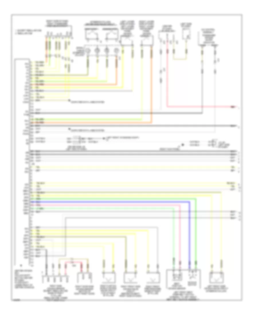 https://portal-diagnostov.com/license.html
Automotive Electricians Portal FZCO
Automotive Electricians Portal FZCO
https://portal-diagnostov.com/license.html
https://portal-diagnostov.com/license.html
Automotive Electricians Portal FZCO
Automotive Electricians Portal FZCO
List of elements for Supplemental Restraints Wiring Diagram (1 of 2) for Toyota Tundra SR 2014:
- (center of dash) j/c j72 & j73
- (left front of engine compt) a1
- (left lower side of dash) left lower instrument panel air bag assembly 1
- (left side of dash) dlc 3
- (right lower side of dash) right lower instrument panel air bag assembly 1
- (right side of dash) front passenger side squib circuit
- (steering column) driver side squib circuit
- +sl
- +sr
- -sl
- -sr
- A/c control assembly
- B21
- Bbd+
- Bbd-
- Bbp+
- Bbp-
- Bbr+
- Bbr-
- Bcr+
- Bcr-
- Buckle switch
- Canh
- Canl
- Center air bag ecu (column shift: bottom center of dash) (floor shift: under front of center console)
- Computer data lines system
- D16
- D2+
- D2-
- D28
- D30
- Dbe+
- Dbe-
- Dk+
- Dk-
- Driver side j/b (left end of dash)
- Dsp+
- Dsp-
- Except regular cab
- First step
- Fsp+
- Fsp-
- Icd+
- Icd-
- Icp+
- Icp-
- Ig2
- J/c j61 (left side of dash)
- J11
- J3 (right kick panel)
- J46
- J72
- J73
- Ji1
- Ji2
- Jj1
- Left front seat inner belt switch (integral to left front seat belt buckle assembly)
- Left front side air bag squib circuit (steering column)
- Mq1
- P-ab
- P2+
- P2-
- Paon
- Passenger air bag on/off indicator
- Pd+
- Pd-
- Pk+
- Pk-
- Pnk
- Pp+
- Pp-
- Red
- Regular cab
- Right curtain shield air bag squib circuit (top of right "b" pillar)
- Right door side air bag sensor (bottom of right front door)
- Right front pretensioner (base of right "b'' pillar)
- Right front side air bag squib circuit (separate seat) (right side of dash)
- Right side air bag sensor (except regular cab: base of right "c" pillar) (regular cab: under right door sill)
- Seat position air bag sensor
- Second step
- Sfd+
- Sfd-
- Sfp+
- Sfp-
- Sil
- Spiral cable (steering column)
- Vhp+
- Vhp-
Supplemental Restraints Wiring Diagram (2 of 2) for Toyota Tundra SR 2014
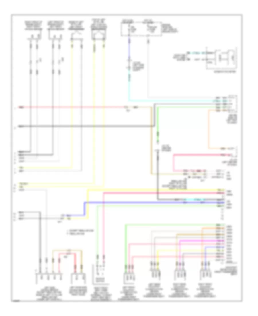 https://portal-diagnostov.com/license.html
Automotive Electricians Portal FZCO
Automotive Electricians Portal FZCO
https://portal-diagnostov.com/license.html
https://portal-diagnostov.com/license.html
Automotive Electricians Portal FZCO
Automotive Electricians Portal FZCO
List of elements for Supplemental Restraints Wiring Diagram (2 of 2) for Toyota Tundra SR 2014:
- (base of left "b'' pillar) left front pretensioner
- (left front of engine compt) left front air bag sensor
- (right front of engine compt) right front air bag sensor
- (top of left "b'' pillar) left curtain shield air bag squib circuit
- +sl
- +sr
- -sl
- -sr
- Aj1
- Aj8
- B13
- B15
- Bbl+
- Bbl-
- Bcl+
- Bcl-
- Bgnd
- Bsw
- Buckle switch
- Can i/f
- Canh
- Canl
- Combination meter
- Computer data lines system
- Cpu
- D14
- D17
- D29
- Dia
- Driver side j/b (left end of dash)
- Ecu-b1 fuse 7.5a
- Engine room r/b (left side of engine compt)
- Except regular cab
- Fsr+
- Fsr-
- Gnd
- Hot at all times
- Hot in on or start
- Ig2
- Ign fuse 10a
- J/c a49 (left side of engine compt)
- J/c j70 (left center of dash)
- J/c j72 (center of dash)
- Left door side air bag sensor (bottom of left front door)
- Left front occupant classification sensor (under front passenger's seat)
- Left rear occupant classification sensor (under front passenger's seat)
- Left side air bag sensor (except regular cab: base of left "c" pillar) (regular cab: (under left door sill)
- Occupant detection ecu (front passenger's seat)
- Pn1
- Pnk
- Q2 (regular cab: right "b'' pillar) (except regular cab: right "c'' pillar)
- Qj1
- Qy1
- Red
- Regular cab
- Right front occupant classification sensor (under front passenger's seat)
- Right front seat inner belt switch (integral to right front seat belt buckle assembly)
- Right rear occupant classification sensor (under front passenger's seat)
- Sgd1
- Sgd2
- Sgd3
- Sgd4
- Sig1
- Sig2
- Sig3
- Sig4
- Svc1
- Svc2
- Svc3
- Svc4
TRANSMISSION
4.0L
4.0L, A/T Wiring Diagram (1 of 3) for Toyota Tundra SR 2014
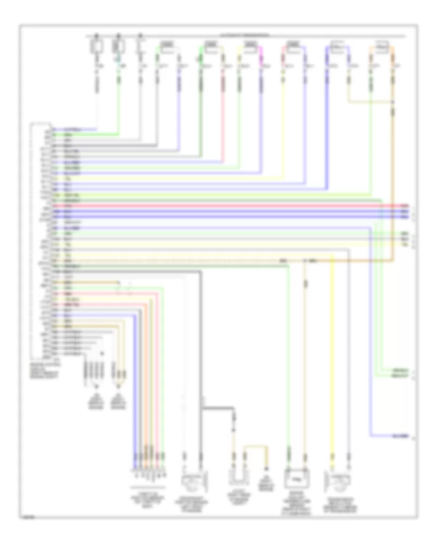 https://portal-diagnostov.com/license.html
Automotive Electricians Portal FZCO
Automotive Electricians Portal FZCO
https://portal-diagnostov.com/license.html
https://portal-diagnostov.com/license.html
Automotive Electricians Portal FZCO
Automotive Electricians Portal FZCO
List of elements for 4.0L, A/T Wiring Diagram (1 of 3) for Toyota Tundra SR 2014:
- +bm
- Automatic transmission
- Crankshaft position sensor (left front of engine)
- D74
- D8 (right rear of engine)
- D9 (right rear of engine)
- E01
- E02
- E03
- E04
- E05
- Engine control module (right rear of engine compt)
- Engine coolant temperature sensor (rear of right cylinder bank)
- Eta
- Ethw
- Ge01
- J/c d71 (right rear of engine compt)
- Me01
- Nca
- Ne+
- Ne-
- Nsw
- Nt+
- Nt-
- Pnk
- Red
- Red sl1+
- Sl1+
- Sl1-
- Sl2+
- Sl2-
- Slt+
- Slt-
- Slu+
- Slu-
- Sp2+
- Sp2-
- Star
- Tho1
- Tho2
- Throttle position sensor (on throttle body)
- Thw
- Transmission revolution sensor (turbine) (in transmission)
- Vcta
- Vta
- Vta1
- Vta2
4.0L, A/T Wiring Diagram (2 of 3) for Toyota Tundra SR 2014
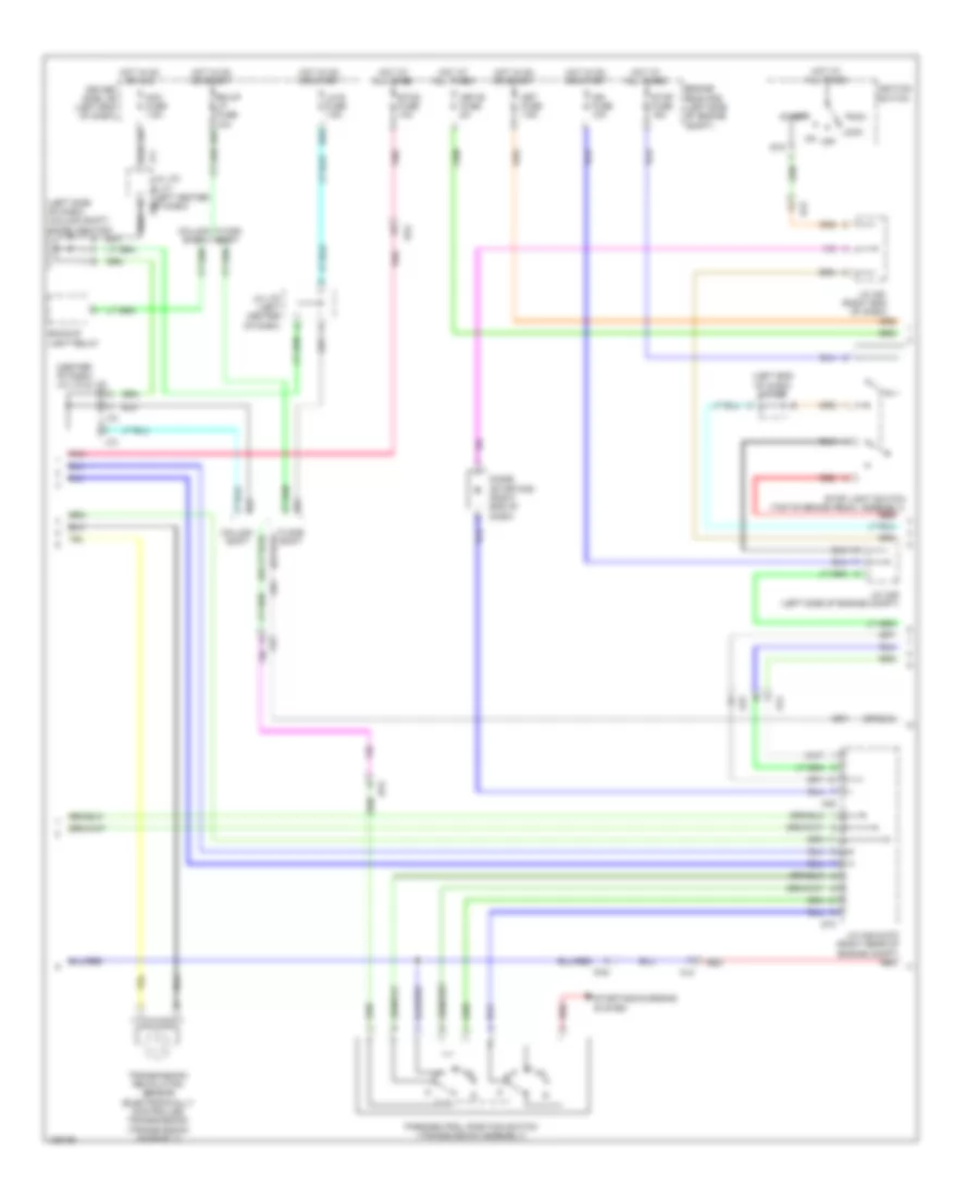 https://portal-diagnostov.com/license.html
Automotive Electricians Portal FZCO
Automotive Electricians Portal FZCO
https://portal-diagnostov.com/license.html
https://portal-diagnostov.com/license.html
Automotive Electricians Portal FZCO
Automotive Electricians Portal FZCO
List of elements for 4.0L, A/T Wiring Diagram (2 of 3) for Toyota Tundra SR 2014:
- (center of dash) j/c j72 & j73
- (left end of dash) j/c a50
- (left side of dash) (column shift) diode (ignition)
- A45
- Acc
- Acc fuse 7.5a
- Aj2
- Aj3
- Aj4
- Aj5
- Backup light relay
- Bk/up lp fuse 10a
- Column shift
- D55
- D65
- D73
- Da2
- Da4
- Diode (starting) (right end of dash)
- Driver side j/b (left end of dash)
- Engine room r/b (left side of engine compt)
- Etcs fuse 10a
- Floor shift
- Hot at all times
- Hot in on or acc
- Hot in on or start
- Ign fuse 10a
- Ignition switch
- J/c a45 & d73 (right rear of engine compt) red
- J/c a49 (left side of engine compt)
- J/c a51 (right end of dash)
- J/c j70 & j71 (left center j70 of dash)
- J/c j70 (left center of dash)
- J71
- J72
- J73
- Lh-ig fuse 7.5a
- Lock
- Met fuse 7.5a
- Met-b fuse 5a
- Off
- Park/neutral position switch (transmission assembly)
- Pnk
- Red
- St2
- Start
- Starting/charging system
- Stop fuse 15a
- Stop light switch (top of brake pedal assembly)
- Transmission revolution sensor (electronically controlled transmission) (transmission assembly)
4.0L, A/T Wiring Diagram (3 of 3) for Toyota Tundra SR 2014
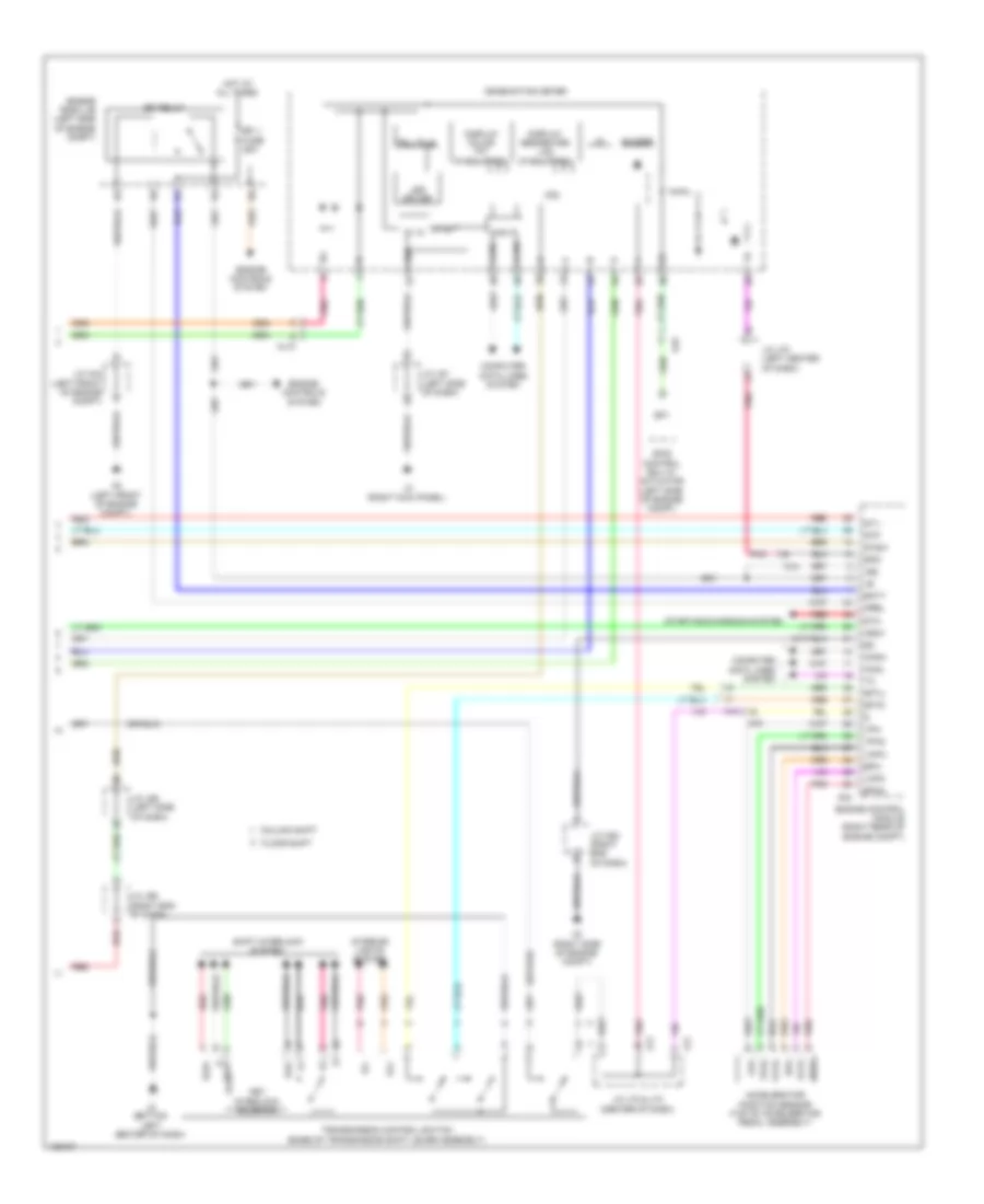 https://portal-diagnostov.com/license.html
Automotive Electricians Portal FZCO
Automotive Electricians Portal FZCO
https://portal-diagnostov.com/license.html
https://portal-diagnostov.com/license.html
Automotive Electricians Portal FZCO
Automotive Electricians Portal FZCO
List of elements for 4.0L, A/T Wiring Diagram (3 of 3) for Toyota Tundra SR 2014:
- +b2
- 5v ic
- 5v+b
- A2 (left front of engine compt)
- A24
- A3 (right side of engine compt)
- Accelerator position sensor (top of accelerator pedal assembly)
- Aj10
- Aj4
- Aj5
- Aj9
- Batt
- Buzzer
- Can if
- Canh
- Canl
- Column shift
- Combination meter
- Computer data lines system
- Cpu
- Display color tft (if equipped)
- Display segmented lcd (if equipped)
- Efi 1 fuse 25a
- Efi relay
- Engine control module (right rear of engine compt)
- Engine controls system
- Engine room j/b (left side of engine compt)
- Epa
- Epa2
- Floor shift
- Hot at all times
- I/f
- Ig+
- Igsw
- Ill+
- Ill-
- Interior lights system
- J/c a44 (left front of engine compt)
- J/c a52 (right end of dash)
- J/c j61 (left side of dash)
- J/c j65 (left side of dash)
- J/c j66 (right end of dash)
- J/c j70 (left center of dash)
- J/c j72 & j73 (center of dash)
- J2 (bottom left center of dash)
- J3 (right kick panel)
- J72
- J73
- Key interlock solenoid
- Kls+ e
- Kls-
- Led driver
- Mrel
- Pnk
- Red
- Sftd
- Sftu
- Shift interlock system
- Skid control ecu w/ actuator (left side of engine compt)
- Sls+
- Sp1
- Spd
- St1-
- Sta
- Starting/charging system
- Stp
- Stsw
- Telltale
- Transmission control switch (base of transmission shift lever assembly)
- Vcp2
- Vcpa
- Vpa
- Vpa2
4.6L
4.6L, 4WD Wiring Diagram for Toyota Tundra SR 2014
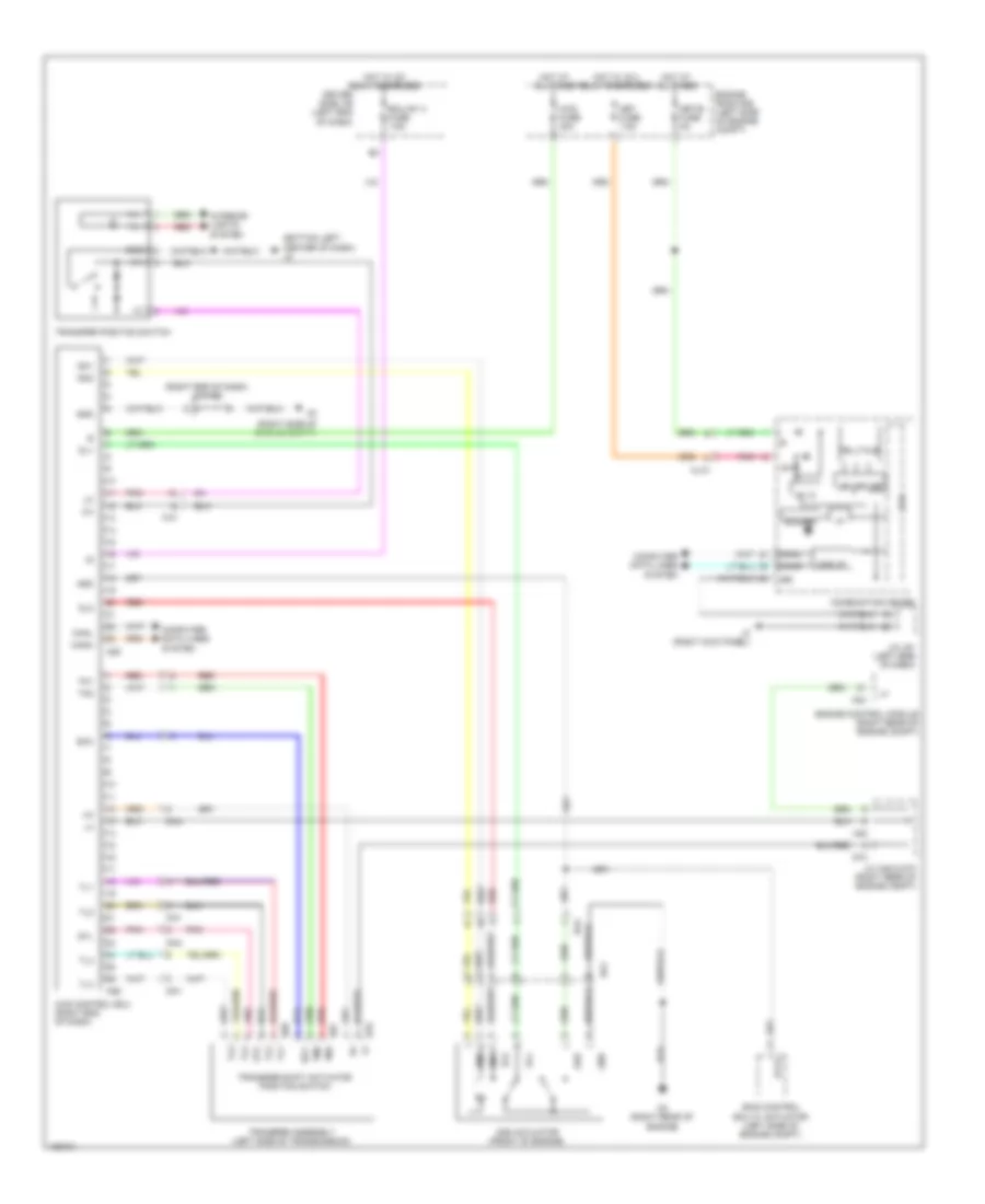 https://portal-diagnostov.com/license.html
Automotive Electricians Portal FZCO
Automotive Electricians Portal FZCO
https://portal-diagnostov.com/license.html
https://portal-diagnostov.com/license.html
Automotive Electricians Portal FZCO
Automotive Electricians Portal FZCO
List of elements for 4.6L, 4WD Wiring Diagram for Toyota Tundra SR 2014:
- (bottom left center of dash) j2
- (right end of dash) j/c a52
- (right side of engine compt)
- 2-4
- 4wd control ecu (right end of dash)
- 4wd fuse 30a
- 5v ic
- A24
- A25
- A26
- A45
- Add
- Add actuator (front of engine)
- Aj10
- Aj3
- Buzzer
- Can i/f
- Canh
- Canl
- Combination meter
- Computer data lines system
- Cpu
- D3 (right rear of engine)
- D67
- D68
- D70
- D73
- Da1
- Da4
- Dg1
- Dl1
- Dl2
- Dm1
- Dm2
- Driver side j/b (left end of dash)
- Ecu-ig1 3 fuse 7.5a
- Engine control module (right rear of engine compt)
- Engine room r/b (left side of engine compt)
- Ex12
- Gnd
- Gtl
- Hot at all times
- Hot w/ ig 2 relay energized
- Hot w/ ig1 relay energized
- I/f
- Ig+
- Ill+
- Ill-
- Interior lights system
- J/c a45 & d73 (right rear of engine compt)
- J/c j61 (left side of dash)
- J3 (right kick panel)
- Led driver
- Met fuse 7.5a
- Met-b fuse 5a
- Pnk
- Red
- Scc
- Skid control ecu w/ actuator (left side of engine compt)
- Telltale
- Tl1
- Tl2
- Tl3
- Tl4
- Tm1
- Tm2
- Transfer assembly (left side of transmission)
- Transfer position switch
- Transfer shift actuator position switch
4.6L, A/T Wiring Diagram (1 of 3) for Toyota Tundra SR 2014
 https://portal-diagnostov.com/license.html
Automotive Electricians Portal FZCO
Automotive Electricians Portal FZCO
https://portal-diagnostov.com/license.html
https://portal-diagnostov.com/license.html
Automotive Electricians Portal FZCO
Automotive Electricians Portal FZCO
List of elements for 4.6L, A/T Wiring Diagram (1 of 3) for Toyota Tundra SR 2014:
- +bm
- Automatic transmission
- Crankshaft position sensor (left front of engine)
- D1 (left rear of engine)
- D2 (right rear of engine)
- D74
- E01
- E02
- E03
- E04
- E05
- Engine control module (right rear of engine compt)
- Engine coolant temperature sensor (front of left cylinder bank)
- Eta
- Ge01
- Me01
- Ne+
- Ne-
- Nsw
- Nt+
- Nt-
- Pnk
- Red
- Red sl1+
- Sl1+
- Sl1-
- Sl2+
- Sl2-
- Slt+
- Slt-
- Slu+
- Slu-
- Sp2+
- Sp2-
- Star
- Tho1
- Tho2
- Throttle position sensor (on throttle body)
- Thw
- Transmission revolution sensor (turbine) (in transmission)
- Vcta
- Vcv2
- Vta
- Vta1
- Vta2
4.6L, A/T Wiring Diagram (2 of 3) for Toyota Tundra SR 2014
 https://portal-diagnostov.com/license.html
Automotive Electricians Portal FZCO
Automotive Electricians Portal FZCO
https://portal-diagnostov.com/license.html
https://portal-diagnostov.com/license.html
Automotive Electricians Portal FZCO
Automotive Electricians Portal FZCO
List of elements for 4.6L, A/T Wiring Diagram (2 of 3) for Toyota Tundra SR 2014:
- (center of dash) j/c j72 & j73
- (left end of dash) j/c a50
- (left side of dash) (column shift) diode (ignition)
- A45
- Acc
- Acc fuse 7.5a
- Aj2
- Aj3
- Aj4
- Aj5
- Backup light relay
- Bk/up lp fuse 10a
- Column shift
- D55
- D65
- D73
- Da2
- Da4
- Diode (starting) (right end of dash)
- Driver side j/b (left end of dash)
- Engine room r/b (left side of engine compt)
- Etcs fuse 10a
- Floor shift
- Hot at all times
- Hot in on or acc
- Hot in on or start
- Ign fuse 10a
- Ignition switch
- J/c a45 & d73 (right rear of engine compt) red
- J/c a51 (right end of dash)
- J/c j70 & j71 (left center j70 of dash)
- J/c j70 (left center of dash)
- J71
- J72
- J73
- Lh-ig fuse 7.5a
- Lock
- Met fuse 7.5a
- Met-b fuse 5a
- Off
- Park/neutral position switch (transmission assembly)
- Pnk
- Red
- St2
- Start
- Starting/charging system
- Stop fuse 15a
- Stop light switch (top of brake pedal assembly)
- Transmission revolution sensor (electronically controlled transmission) (transmission assembly)
4.6L, A/T Wiring Diagram (3 of 3) for Toyota Tundra SR 2014
 https://portal-diagnostov.com/license.html
Automotive Electricians Portal FZCO
Automotive Electricians Portal FZCO
https://portal-diagnostov.com/license.html
https://portal-diagnostov.com/license.html
Automotive Electricians Portal FZCO
Automotive Electricians Portal FZCO
List of elements for 4.6L, A/T Wiring Diagram (3 of 3) for Toyota Tundra SR 2014:
- +b2
- 5v ic
- 5v+b
- A2 (left front of engine compt)
- A24
- A3 (right side of engine compt)
- Accelerator position sensor (top of accelerator pedal assembly)
- Aj10
- Aj4
- Aj5
- Aj9
- Batt
- Buzzer
- Can if
- Canh
- Canl
- Column shift
- Combination meter
- Computer data lines system
- Cpu
- Display colour tft (if equipped)
- Display segmented lcd (if equipped)
- E kls+
- Efi 1 fuse 25a
- Efi relay
- Engine control module (right rear of engine compt)
- Engine controls system
- Engine room j/b (left side of engine compt)
- Epa
- Epa2
- Floor shift
- Hot at all times
- I/f
- Ig+
- Igsw
- Ill+
- Ill-
- Interior lights system
- J/c a44 (left front of engine compt)
- J/c a52 (right end of dash)
- J/c j61 (left side of dash)
- J/c j65 (left side of dash)
- J/c j66 (right end of dash)
- J/c j70 (left center of dash)
- J/c j72 & j73 (center of dash)
- J2 (bottom left center of dash)
- J3 (right kick panel)
- J72
- J73
- Key interlock solenoid
- Kls-
- Led driver
- Mrel
- Pnk
- Red
- Sftd
- Sftu
- Shift inter lock system
- Skid control ecu w/ actuator (left side of engine compt)
- Sls+
- Sp1
- Spd
- St1-
- Sta
- Starting/charging system
- Stp
- Stsw
- Telltale
- Transmission control switch (base of transmission shift lever assembly)
- Vcp2
- Vcpa
- Vpa
- Vpa2
5.7L
5.7L, 4WD Wiring Diagram for Toyota Tundra SR 2014
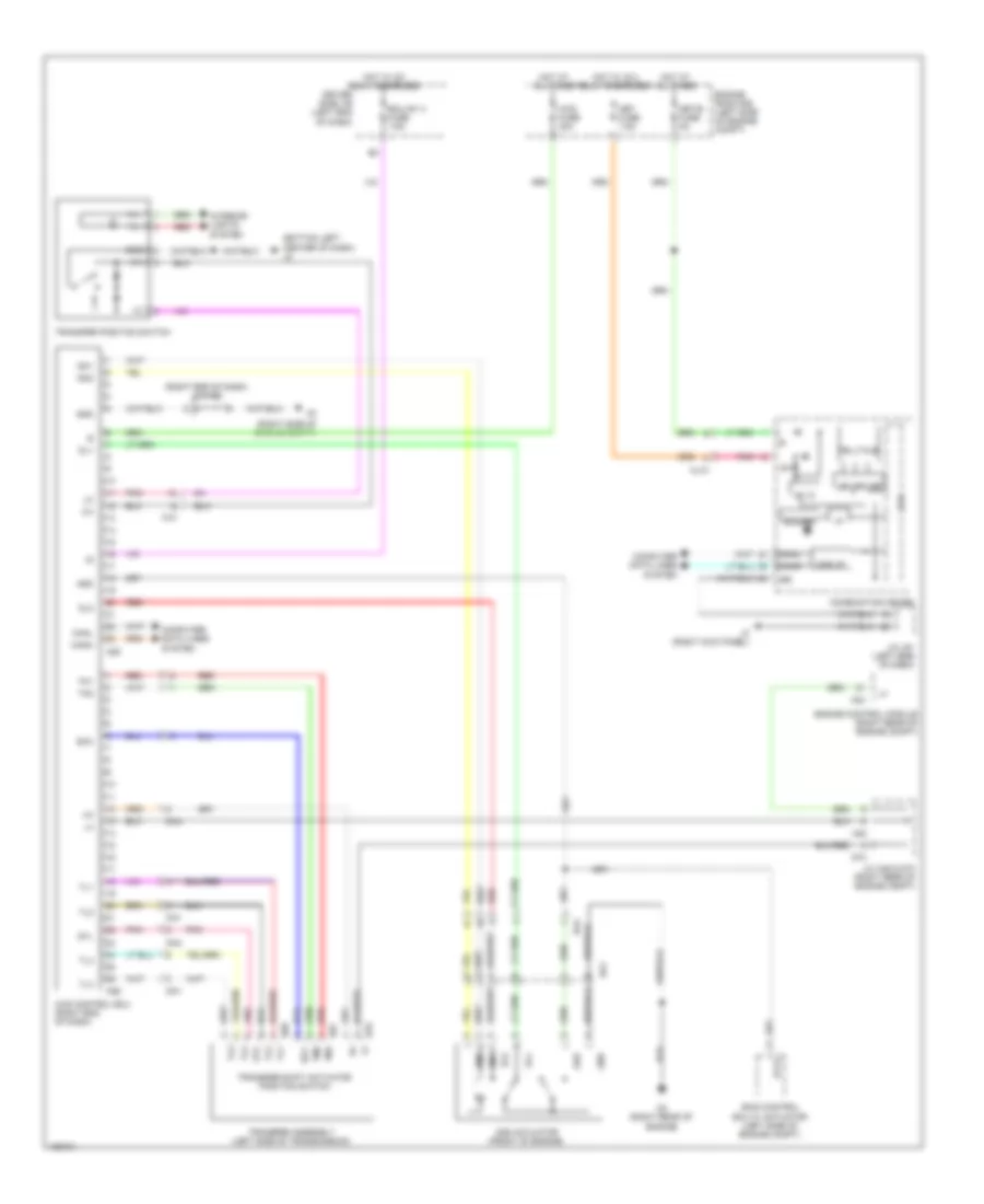 https://portal-diagnostov.com/license.html
Automotive Electricians Portal FZCO
Automotive Electricians Portal FZCO
https://portal-diagnostov.com/license.html
https://portal-diagnostov.com/license.html
Automotive Electricians Portal FZCO
Automotive Electricians Portal FZCO
List of elements for 5.7L, 4WD Wiring Diagram for Toyota Tundra SR 2014:
- (bottom left center of dash) j2
- (right end of dash) j/c a52
- (right side of engine compt)
- 2-4
- 4wd control ecu (right end of dash)
- 4wd fuse 30a
- 5v ic
- A24
- A25
- A26
- A45
- Add
- Add actuator (front of engine)
- Aj10
- Aj3
- Buzzer
- Can i/f
- Canh
- Canl
- Combination meter
- Computer data lines system
- Cpu
- D3 (right rear of engine)
- D67
- D68
- D70
- D73
- Da1
- Da4
- Dg1
- Dl1
- Dl2
- Dm1
- Dm2
- Driver side j/b (left end of dash)
- Ecu-ig1 3 fuse 7.5a
- Engine control module (right rear of engine compt)
- Engine room r/b (left side of engine compt)
- Ex12
- Gnd
- Gtl
- Hot at all times
- Hot w/ ig 2 relay energized
- Hot w/ ig1 relay energized
- I/f
- Ig+
- Ill+
- Ill-
- Interior lights system
- J/c a45 & d73 (right rear of engine compt)
- J/c j61 (left side of dash)
- J3 (right kick panel)
- Led driver
- Met fuse 7.5a
- Met-b fuse 5a
- Pnk
- Red
- Scc
- Skid control ecu w/ actuator (left side of engine compt)
- Telltale
- Tl1
- Tl2
- Tl3
- Tl4
- Tm1
- Tm2
- Transfer assembly (left side of transmission)
- Transfer position switch
- Transfer shift actuator position switch
5.7L, A/T Wiring Diagram (1 of 3) for Toyota Tundra SR 2014
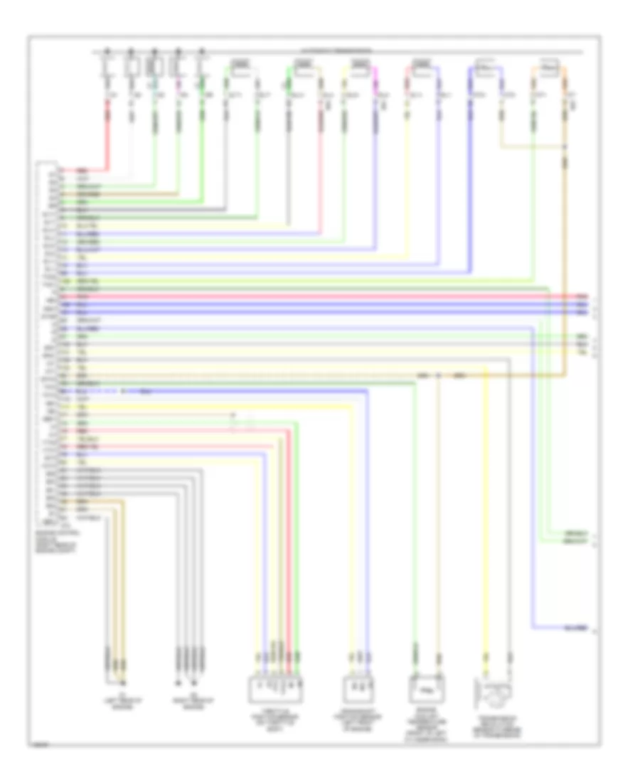 https://portal-diagnostov.com/license.html
Automotive Electricians Portal FZCO
Automotive Electricians Portal FZCO
https://portal-diagnostov.com/license.html
https://portal-diagnostov.com/license.html
Automotive Electricians Portal FZCO
Automotive Electricians Portal FZCO
List of elements for 5.7L, A/T Wiring Diagram (1 of 3) for Toyota Tundra SR 2014:
- +bm
- Automatic transmission
- Crankshaft position sensor (left front of engine)
- D1 (left rear of engine)
- D2 (right rear of engine)
- D63
- D64
- D74
- E01
- E02
- E03
- E04
- E05
- Engine control module (right rear of engine compt)
- Engine coolant temperature sensor (front of left cylinder bank)
- Eta
- Etha
- Ge01
- Me01
- Ne+
- Ne-
- Nsw
- Nt+
- Nt-
- Pnk
- Red
- Red sl1+
- Sl1+
- Sl1-
- Sl2+
- Sl2-
- Slt+
- Slt-
- Slu+
- Slu-
- Sp2+
- Sp2-
- Star
- Tho1
- Tho2
- Throttle position sensor (on throttle body)
- Thw
- Transmission revolution sensor (turbine) (in transmission)
- Vcta
- Vcv2
- Vta
- Vta1
- Vta2
5.7L, A/T Wiring Diagram (2 of 3) for Toyota Tundra SR 2014
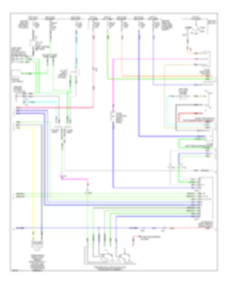 https://portal-diagnostov.com/license.html
Automotive Electricians Portal FZCO
Automotive Electricians Portal FZCO
https://portal-diagnostov.com/license.html
https://portal-diagnostov.com/license.html
Automotive Electricians Portal FZCO
Automotive Electricians Portal FZCO
List of elements for 5.7L, A/T Wiring Diagram (2 of 3) for Toyota Tundra SR 2014:
- (center of dash) j/c j72 & j73
- (left end of dash) j/c a50
- (left side of dash) (column shift) diode (ignition)
- A45
- Acc
- Acc fuse 7.5a
- Aj3
- Aj4
- Aj5
- Backup light relay
- Bk/up lp fuse 10a
- Column shift
- D55
- D65
- D73
- Da2
- Da4
- Diode (starting) (right end of dash)
- Driver side j/b (left end of dash)
- Engine room r/b (left side of engine compt)
- Etcs fuse 10a
- Floor shift
- Hot at all times
- Hot in on or acc
- Hot in on or start
- Ign fuse 10a
- Ignition switch
- J/c a45 & d73 (right rear of engine compt)
- J/c a49 (left side of engine compt)
- J/c j70 & j71 (left center j70 of dash)
- J/c j70 (left center of dash)
- J71
- J72
- J73
- Lh-ig fuse 7.5a
- Lock
- Met fuse 7.5a
- Met-b fuse 5a
- Off
- Park/neutral position switch (transmission assembly)
- Pnk
- Red
- St2
- Start
- Starting/charging system
- Stop fuse 15a
- Stop light switch (top of brake pedal assembly)
- Transmission revolution sensor (electronically controlled transmission) (transmission assembly)
5.7L, A/T Wiring Diagram (3 of 3) for Toyota Tundra SR 2014
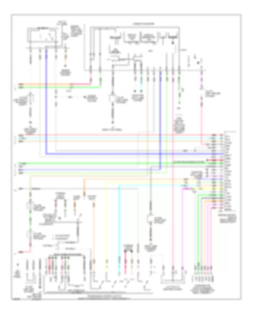 https://portal-diagnostov.com/license.html
Automotive Electricians Portal FZCO
Automotive Electricians Portal FZCO
https://portal-diagnostov.com/license.html
https://portal-diagnostov.com/license.html
Automotive Electricians Portal FZCO
Automotive Electricians Portal FZCO
List of elements for 5.7L, A/T Wiring Diagram (3 of 3) for Toyota Tundra SR 2014:
- (bottom left center of dash)
- +b2
- 5v ic
- 5v+b
- A2 (left front of engine compt)
- A24
- A3 (right side of engine compt)
- Accelerator position sensor (top of accelerator pedal assembly)
- Aj10
- Aj4
- Aj5
- Aj9
- Batt
- Buzzer
- Can if
- Canh
- Canl
- Column shift
- Combination meter
- Computer data lines system
- Cpu
- Display color tft (if equipped)
- Display segmented lcd (if equipped)
- Efi 1 fuse 25a
- Efi relay
- Engine control module (right rear of engine compt)
- Engine controls system
- Engine room j/b (left side of engine compt)
- Epa
- Epa2
- Floor shift
- Hot at all times
- I/f
- Ig+
- Igsw
- Ill+
- Ill-
- Interior lights system
- J/c a44 (left front of engine compt)
- J/c a52 (right end of dash)
- J/c j60 (left end of dash)
- J/c j61 (left side of dash)
- J/c j65 (left side of dash)
- J/c j66 (right end of dash)
- J/c j70 (left center of dash)
- J/c j72 & j73 (center of dash)
- J1 (left kick panel)
- J3 (right kick panel)
- J72
- J73
- Key interlock solenoid
- Kls+
- Kls-
- Led driver
- Mrel
- P1 e
- Pnk
- Pwr
- Red
- Sftd
- Sftu
- Shift interlock system
- Skid control ecu w/ actuator (left side of engine compt)
- Sls+
- Sp1
- Spd
- St1-
- Sta
- Starting/charging system
- Stp
- Stsw
- Telltale
- Tow/haul pattern select switch (floor shift)
- Transmission control switch (base of transmission shift lever assembly)
- Vcp2
- Vcpa
- Vpa
- Vpa2
5.7L FLEX FUEL
5.7L Flex Fuel, 4WD Wiring Diagram for Toyota Tundra SR 2014
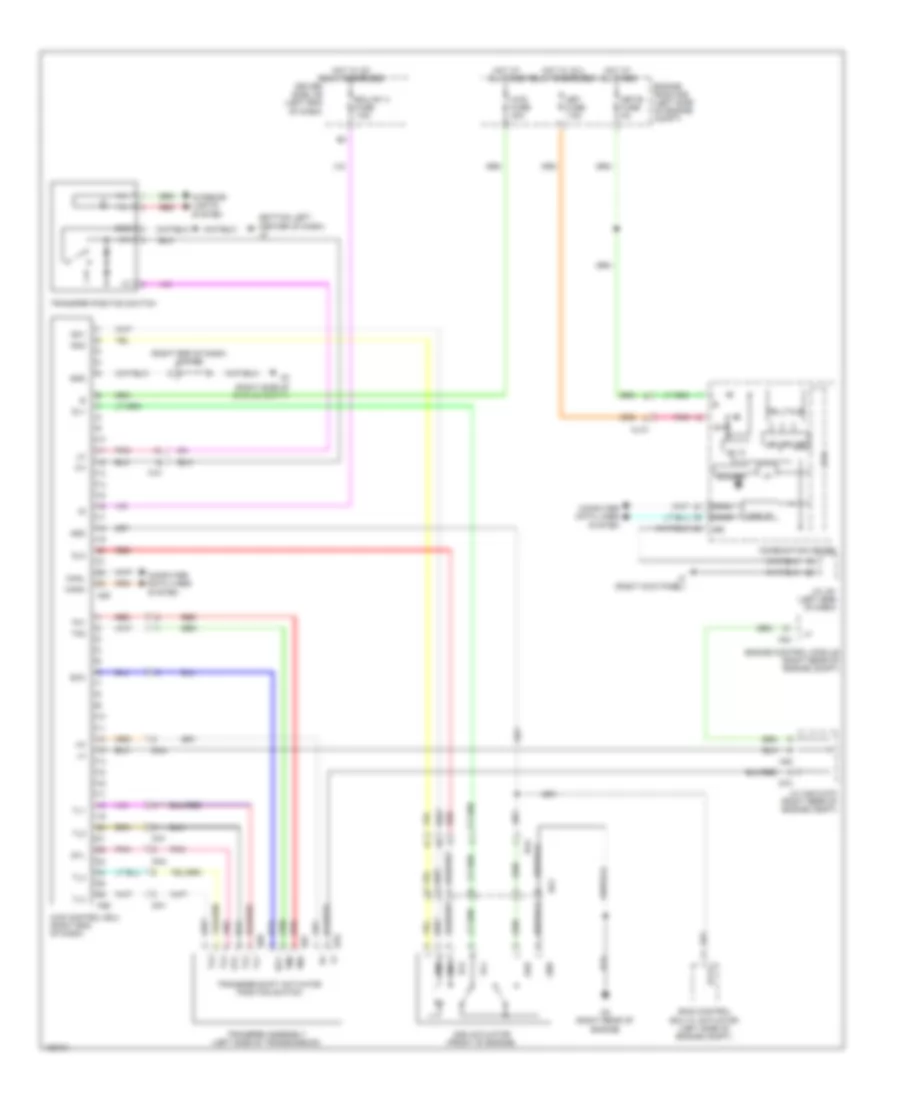 https://portal-diagnostov.com/license.html
Automotive Electricians Portal FZCO
Automotive Electricians Portal FZCO
https://portal-diagnostov.com/license.html
https://portal-diagnostov.com/license.html
Automotive Electricians Portal FZCO
Automotive Electricians Portal FZCO
List of elements for 5.7L Flex Fuel, 4WD Wiring Diagram for Toyota Tundra SR 2014:
- (bottom left center of dash) j2
- (right end of dash) j/c a52
- (right side of engine compt)
- 2-4
- 4wd control ecu (right end of dash)
- 4wd fuse 30a
- 5v ic
- A24
- A25
- A26
- A45
- Add
- Add actuator (front of engine)
- Aj10
- Aj3
- Buzzer
- Can i/f
- Canh
- Canl
- Combination meter
- Computer data lines system
- Cpu
- D3 (right rear of engine)
- D67
- D68
- D70
- D73
- Da1
- Da4
- Dg1
- Dl1
- Dl2
- Dm1
- Dm2
- Driver side j/b (left end of dash)
- Ecu-ig1 3 fuse 7.5a
- Engine control module (right rear of engine compt)
- Engine room r/b (left side of engine compt)
- Ex12
- Gnd
- Gtl
- Hot at all times
- Hot w/ ig 2 relay energized
- Hot w/ ig1 relay energized
- I/f
- Ig+
- Ill+
- Ill-
- Interior lights system
- J/c a45 & d73 (right rear of engine compt)
- J/c j61 (left side of dash)
- J3 (right kick panel)
- Led driver
- Met fuse 7.5a
- Met-b fuse 5a
- Pnk
- Red
- Scc
- Skid control ecu w/ actuator (left side of engine compt)
- Telltale
- Tl1
- Tl2
- Tl3
- Tl4
- Tm1
- Tm2
- Transfer assembly (left side of transmission)
- Transfer position switch
- Transfer shift actuator position switch
5.7L Flex Fuel, A/T Wiring Diagram (1 of 3) for Toyota Tundra SR 2014
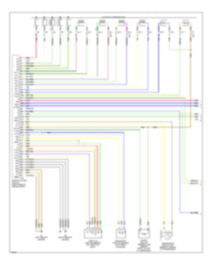 https://portal-diagnostov.com/license.html
Automotive Electricians Portal FZCO
Automotive Electricians Portal FZCO
https://portal-diagnostov.com/license.html
https://portal-diagnostov.com/license.html
Automotive Electricians Portal FZCO
Automotive Electricians Portal FZCO
List of elements for 5.7L Flex Fuel, A/T Wiring Diagram (1 of 3) for Toyota Tundra SR 2014:
- +bm
- Automatic transmission
- Crankshaft position sensor (left front of engine)
- D1 (left rear of engine)
- D2 (right rear of engine)
- D63
- D64
- D74
- E01
- E02
- E03
- E04
- E05
- Engine control module (right rear of engine compt)
- Engine coolant temperature sensor (front of left cylinder bank)
- Eta
- Etha
- Ge01
- Me01
- Ne+
- Ne-
- Nsw
- Nt+
- Nt-
- Pnk
- Red
- Red sl1+
- Sl1+
- Sl1-
- Sl2+
- Sl2-
- Slt+
- Slt-
- Slu+
- Slu-
- Sp2+
- Sp2-
- Star
- Tho1
- Tho2
- Throttle position sensor (on throttle body)
- Thw
- Transmission revolution sensor (turbine) (in transmission)
- Vcta
- Vcv2
- Vta
- Vta1
- Vta2
5.7L Flex Fuel, A/T Wiring Diagram (2 of 3) for Toyota Tundra SR 2014
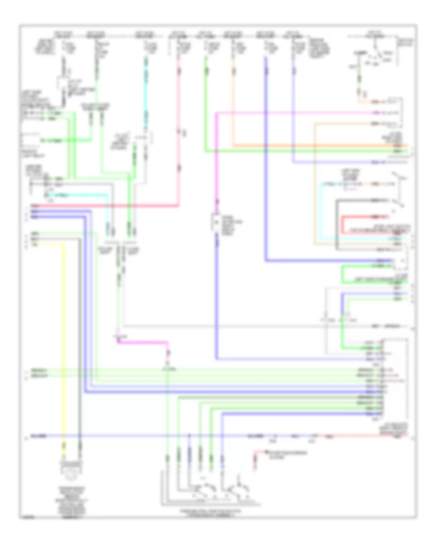 https://portal-diagnostov.com/license.html
Automotive Electricians Portal FZCO
Automotive Electricians Portal FZCO
https://portal-diagnostov.com/license.html
https://portal-diagnostov.com/license.html
Automotive Electricians Portal FZCO
Automotive Electricians Portal FZCO
List of elements for 5.7L Flex Fuel, A/T Wiring Diagram (2 of 3) for Toyota Tundra SR 2014:
- (center of dash) j/c j72 & j73
- (left end of dash) j/c a50
- (left side of dash) (column shift) diode (ignition)
- A45
- Acc
- Acc fuse 7.5a
- Aj3
- Aj4
- Aj5
- Backup light relay
- Bk/up lp fuse 10a
- Column shift
- D55
- D65
- D73
- Da2
- Da4
- Diode (starting) (right end of dash)
- Driver side j/b (left end of dash)
- Engine room r/b (left side of engine compt)
- Etcs fuse 10a
- Floor shift
- Hot at all times
- Hot in on or acc
- Hot in on or start
- Ign fuse 10a
- Ignition switch
- J/c a45 & d73 (right rear of engine compt)
- J/c a49 (left side of engine compt)
- J/c j70 & j71 (left center j70 of dash)
- J/c j70 (left center of dash)
- J71
- J72
- J73
- Lh-ig fuse 7.5a
- Lock
- Met fuse 7.5a
- Met-b fuse 5a
- Off
- Park/neutral position switch (transmission assembly)
- Pnk
- Red
- St2
- Start
- Starting/charging system
- Stop fuse 15a
- Stop light switch (top of brake pedal assembly)
- Transmission revolution sensor (electronically controlled transmission) (transmission assembly)
5.7L Flex Fuel, A/T Wiring Diagram (3 of 3) for Toyota Tundra SR 2014
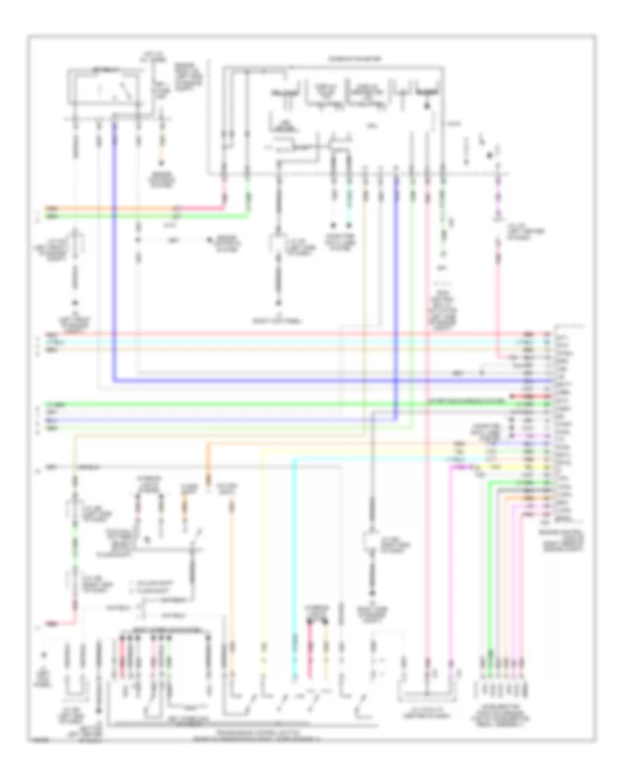 https://portal-diagnostov.com/license.html
Automotive Electricians Portal FZCO
Automotive Electricians Portal FZCO
https://portal-diagnostov.com/license.html
https://portal-diagnostov.com/license.html
Automotive Electricians Portal FZCO
Automotive Electricians Portal FZCO
List of elements for 5.7L Flex Fuel, A/T Wiring Diagram (3 of 3) for Toyota Tundra SR 2014:
- (bottom left center of dash)
- +b2
- 5v ic
- 5v+b
- A2 (left front of engine compt)
- A24
- A3 (right side of engine compt)
- Accelerator position sensor (top of accelerator pedal assembly)
- Aj10
- Aj4
- Aj5
- Aj9
- Batt
- Buzzer
- Can if
- Canh
- Canl
- Column shift
- Combination meter
- Computer data lines system
- Cpu
- Display color tft (if equipped)
- Display segmented lcd (if equipped)
- Efi 1 fuse 25a
- Efi relay
- Engine control module (right rear of engine compt)
- Engine controls system
- Engine room j/b (left side of engine compt)
- Epa
- Epa2
- Floor shift
- Hot at all times
- I/f
- Ig+
- Igsw
- Ill+
- Ill-
- Interior lights system
- J/c a44 (left front of engine compt)
- J/c a52 (right end of dash)
- J/c j60 (left end of dash)
- J/c j61 (left side of dash)
- J/c j65 (left side of dash)
- J/c j66 (right end of dash)
- J/c j70 (left center of dash)
- J/c j72 & j73 (center of dash)
- J1 (left kick panel)
- J3 (right kick panel)
- J72
- J73
- Key interlock solenoid
- Kls+
- Kls-
- Led driver
- Mrel
- P1 e
- Pnk
- Pwr
- Red
- Sftd
- Sftu
- Shift interlock system
- Skid control ecu w/ actuator (left side of engine compt)
- Sls+
- Sp1
- Spd
- St1-
- Sta
- Starting/charging system
- Stp
- Stsw
- Telltale
- Tow/haul pattern select switch (floor shift)
- Transmission control switch (base of transmission shift lever assembly)
- Vcp2
- Vcpa
- Vpa
- Vpa2
WARNING SYSTEMS
Key Reminder & Seat Belt Warning Wiring Diagram for Toyota Tundra SR 2014
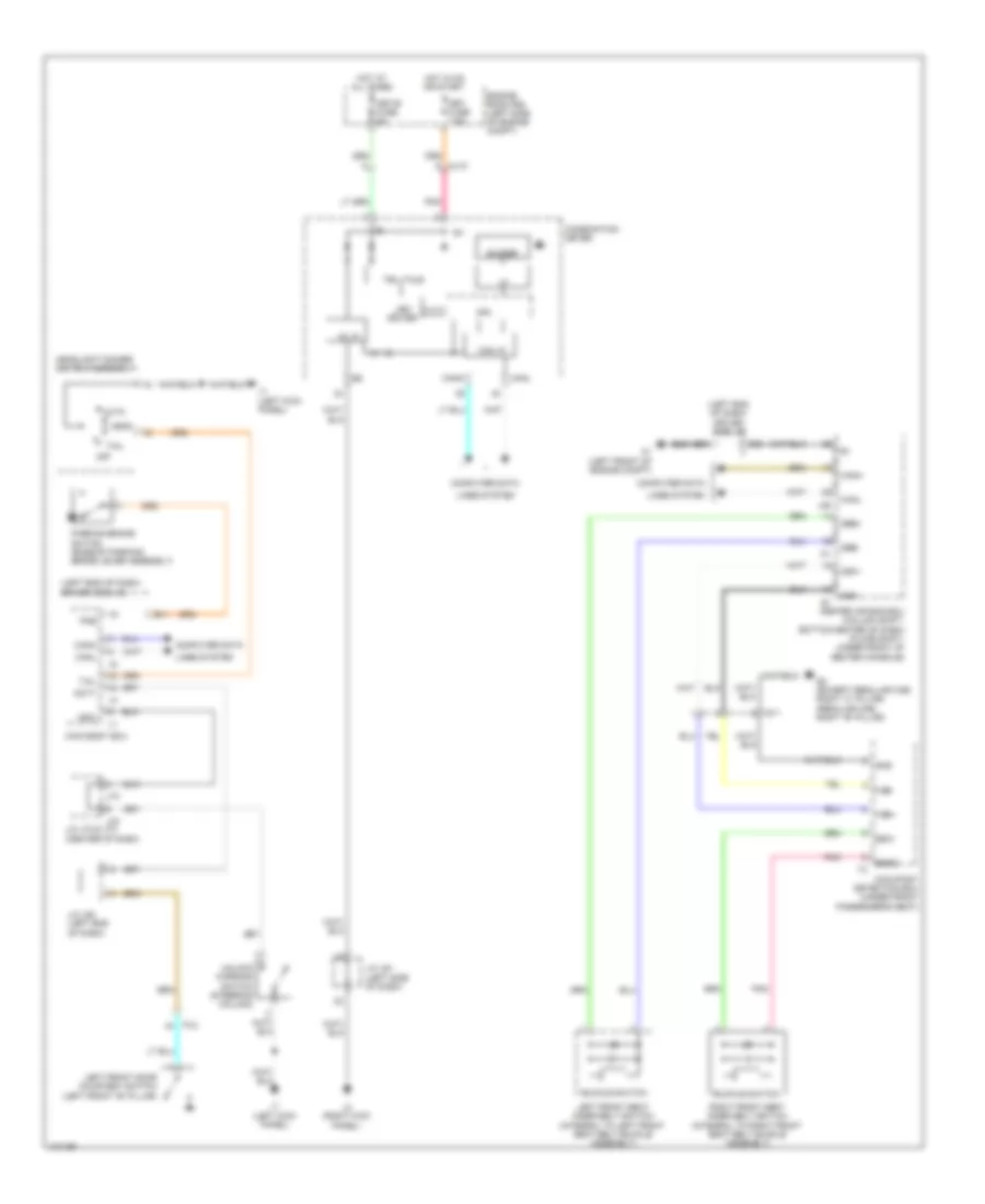 https://portal-diagnostov.com/license.html
Automotive Electricians Portal FZCO
Automotive Electricians Portal FZCO
https://portal-diagnostov.com/license.html
https://portal-diagnostov.com/license.html
Automotive Electricians Portal FZCO
Automotive Electricians Portal FZCO
List of elements for Key Reminder & Seat Belt Warning Wiring Diagram for Toyota Tundra SR 2014:
- (left end of dash) driver side j/b
- 5v +b
- 5v ic
- A1 (left front of engine compt)
- Aj10
- Auto
- B11
- Bgnd
- Bsw
- Buckle switch
- Buzzer
- Can i/f
- Canh
- Canl
- Center air bag ecu (column shift: bottom center of dash) (floor shift: under front of center console)
- Combination meter
- Computer data
- Cpu
- D30
- Dbe+
- Dbe-
- Dcty
- Engine room r/b (left side of engine compt)
- Fsp+
- Fsp-
- Fsr+
- Fsr-
- Gnd
- Head
- Headlight dimmer switch assembly
- Hot at all times
- Hot in on or start
- I/f
- Ig+
- J/c j61 (left side of dash)
- J/c j64 (left end of dash)
- J/c j72 & j73 (center of dash)
- J1 (left kick panel)
- J3 (right kick panel)
- J46
- J72
- J73
- Ksw
- Led driver
- Left front door courtesy switch (left front "b" pillar)
- Left front seat inner belt switch (integral to left front seat belt buckle assembly)
- Lines system
- Main body ecu
- Met fuse 7.5a
- Met-b fuse 5a
- Occupant detection ecu (under front passenger's seat)
- Off
- Parking brake switch (base of parking brake lever assembly)
- Pj2
- Pkb
- Pnk
- Q2 (except regular cab: right "c" pillar) (regular cab: right "b" pillar)
- Qy1
- Right front seat inner belt switch (integral to right front seat belt buckle assembly)
- Tail
- Telltale
- Unlock warning switch (steering column)
Tire Pressure Monitoring Wiring Diagram for Toyota Tundra SR 2014
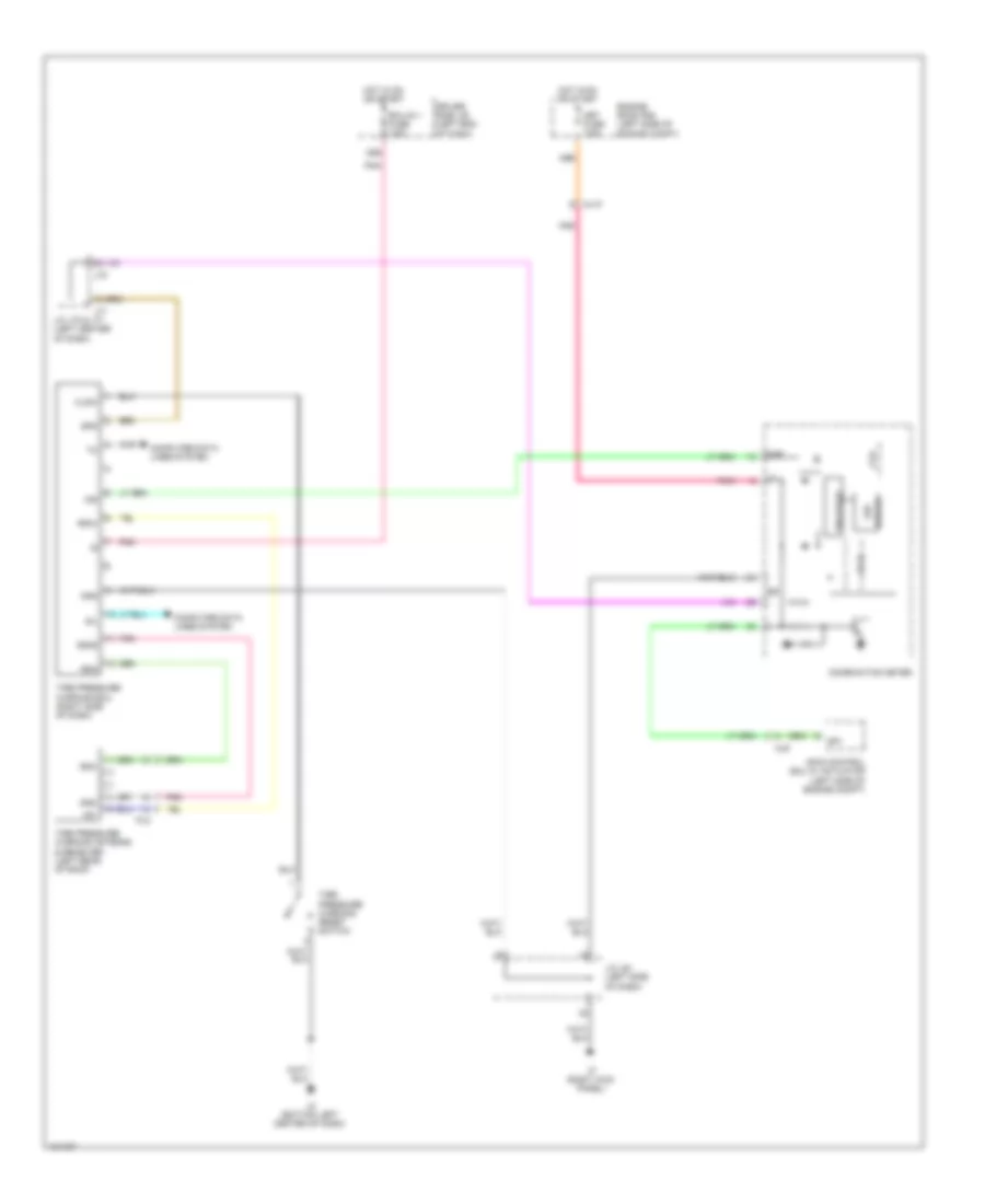 https://portal-diagnostov.com/license.html
Automotive Electricians Portal FZCO
Automotive Electricians Portal FZCO
https://portal-diagnostov.com/license.html
https://portal-diagnostov.com/license.html
Automotive Electricians Portal FZCO
Automotive Electricians Portal FZCO
List of elements for Tire Pressure Monitoring Wiring Diagram for Toyota Tundra SR 2014:
- +5v
- 5v ic
- Aj10
- Aj9
- Clsw
- Combination meter
- Computer data lines system
- Cpu
- D56
- Driver
- Driver side j/b (left end of dash)
- Ecu-ig 1 fuse 7.5a
- Engine room r/b (left side of engine compt)
- Gnd
- Gnd2
- Hot in on or start
- I/f
- Ig+
- Ind
- J/c j61 (left side of dash)
- J/c j70 & j71 (left center of dash)
- J2 (bottom left center of dash)
- J3 (right kick panel)
- J70
- J71
- Led
- Met fuse 7.5a
- Pj2
- Pnk
- Rda
- Rf5v
- Sil
- Skid control ecu w/ actuator (left side of engine compt)
- Sp1
- Spd
- Telltale
- Tire
- Tire pressure warning antenna & receiver (left rear of roof)
- Tire pressure warning ecu (right side of dash)
- Tire pressure warning reset switch
WIPER/WASHER
Wiper/Washer Wiring Diagram, with Intermittent for Toyota Tundra SR 2014
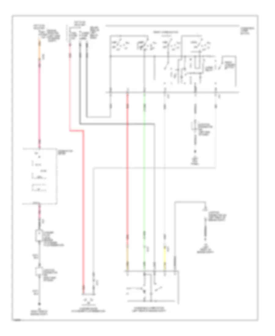 https://portal-diagnostov.com/license.html
Automotive Electricians Portal FZCO
Automotive Electricians Portal FZCO
https://portal-diagnostov.com/license.html
https://portal-diagnostov.com/license.html
Automotive Electricians Portal FZCO
Automotive Electricians Portal FZCO
List of elements for Wiper/Washer Wiring Diagram, with Intermittent for Toyota Tundra SR 2014:
- 1g+
- 5v ic
- 5v+b
- A2 (left front of engine compt)
- A4 (right side of engine compt)
- Aj10
- Aj11
- Aj4
- Combination meter
- Cpu
- D66
- Driver side j/b (left end of dash)
- Engine room r/b (left side of engine compt)
- Front washer switch
- Front wiper switch
- Hot in on or start
- I/f
- Int
- J1 (left kick panel)
- J12
- J13
- Junction connector a44 (left front of engine compt)
- Junction connector a52 (right end of dash)
- Junction connector j60 (left end of dash)
- Met fuse 7.5a
- Mist
- Off
- Pnk
- Red
- Washer fluid level sensor (in washer fluid reservoir)
- Washer motor (in washer fluid reservoir)
- Windshield wiper motor (left rear of engine compt)
- Windshield wiper switch
- Wiper fuse 30a
- Wiper relay
- Wlvl
- Wsh fuse 20a
Wiper/Washer Wiring Diagram, without Intermittent for Toyota Tundra SR 2014
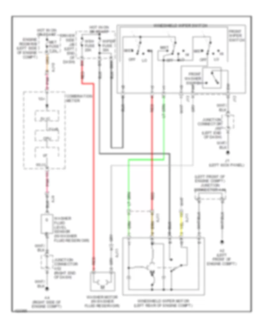 https://portal-diagnostov.com/license.html
Automotive Electricians Portal FZCO
Automotive Electricians Portal FZCO
https://portal-diagnostov.com/license.html
https://portal-diagnostov.com/license.html
Automotive Electricians Portal FZCO
Automotive Electricians Portal FZCO
List of elements for Wiper/Washer Wiring Diagram, without Intermittent for Toyota Tundra SR 2014:
- (left front of engine compt) junction connector a44
- 1g+
- 5v ic
- 5v+b
- A2 (left front of engine compt)
- A4 (right side of engine compt)
- Aj10
- Aj11
- Aj4
- Combination meter
- Cpu
- D66
- Driver side j/b (left end of dash)
- Engine room r/b (left side of engine compt)
- Front washer switch
- Front wiper switch
- Hot in on or start
- I/f
- J1 (left kick panel)
- J12
- J13
- Junction connector a52 (right end of dash)
- Junction connector j60 (left end of dash)
- Met fuse 7.5a
- Mist
- Off
- Pnk
- Red
- Washer fluid level sensor (in washer fluid reservoir)
- Washer motor (in washer fluid reservoir)
- Windshield wiper motor (left rear of engine compt)
- Windshield wiper switch
- Wiper fuse 30a
- Wlvl
- Wsh fuse 20a
 Deutsch
 English
 English
 Español
 Français
 Nederlands
 Русский


