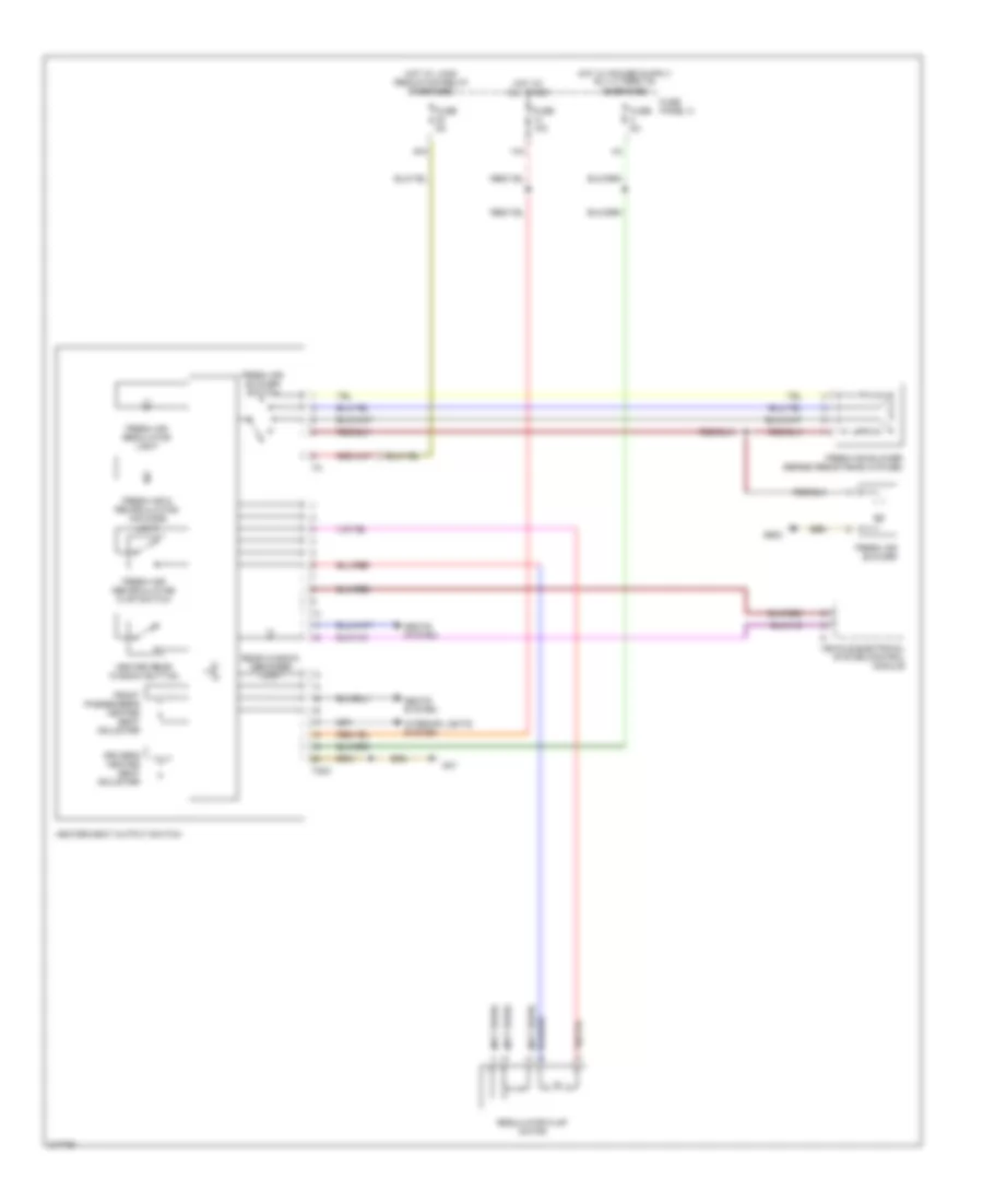
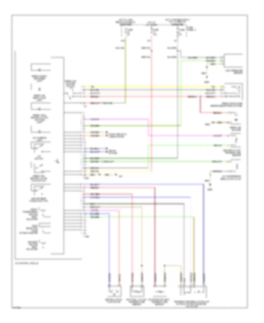
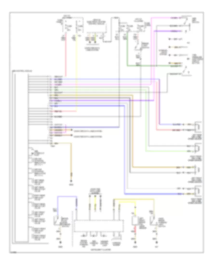
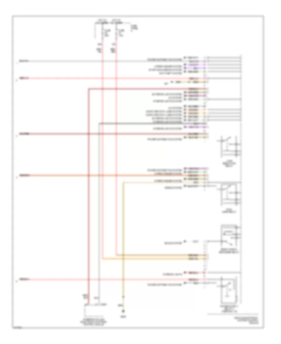
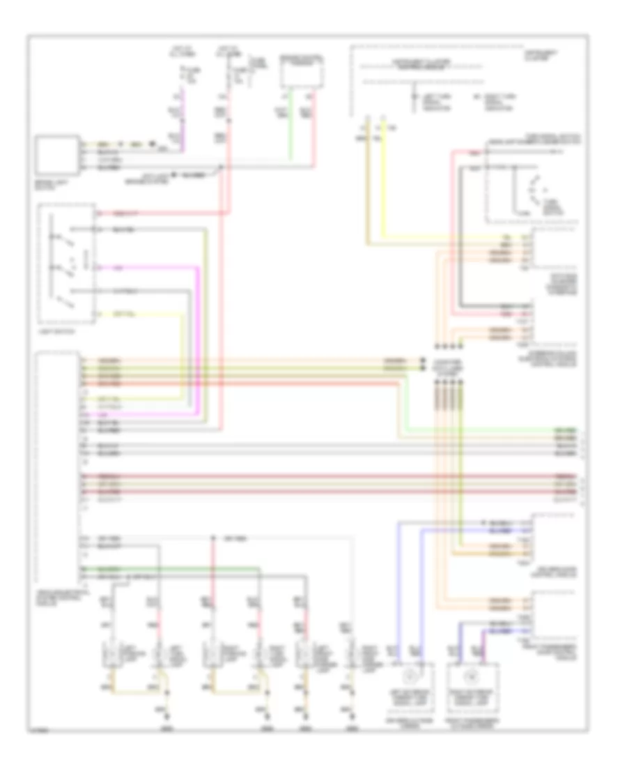
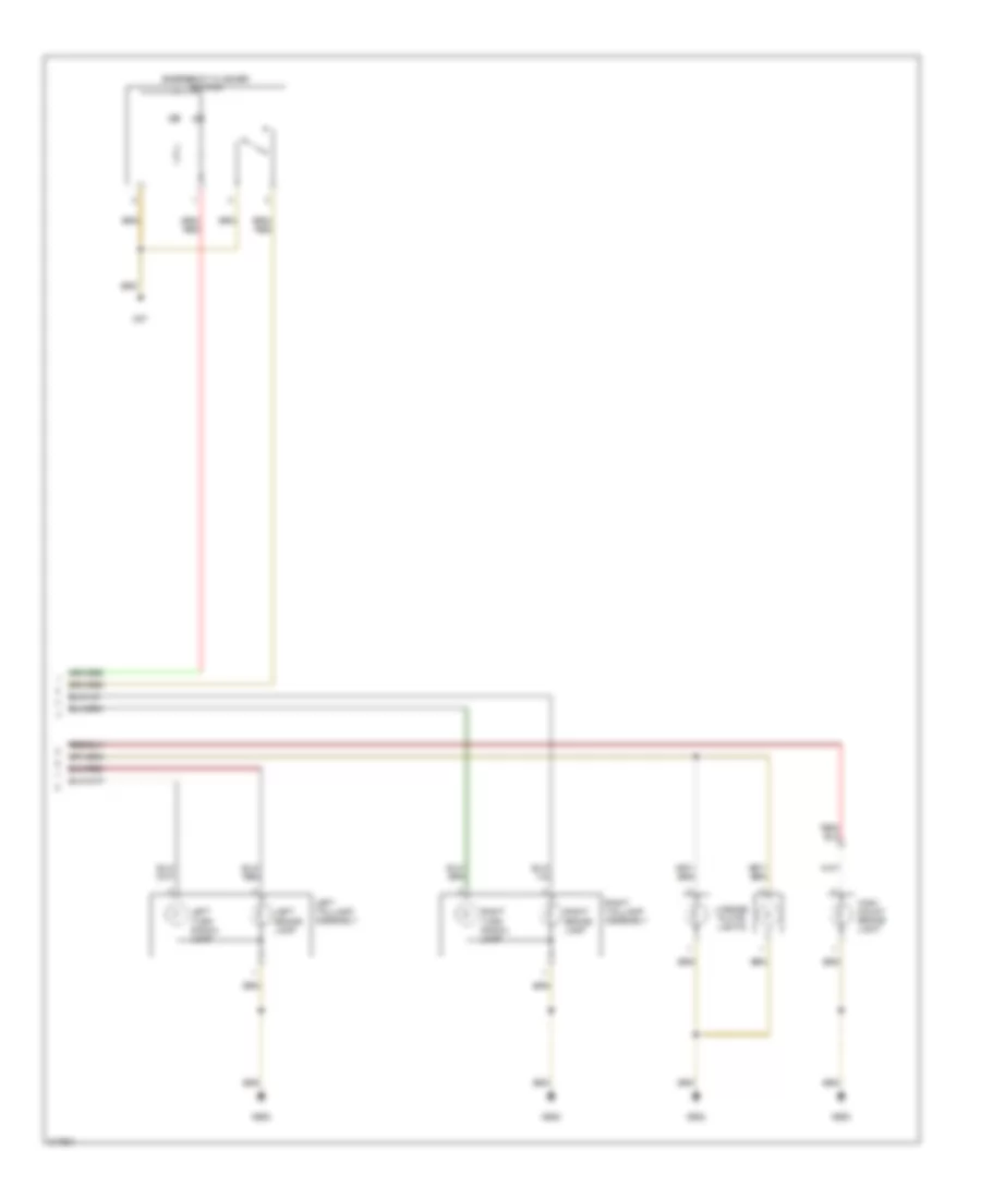
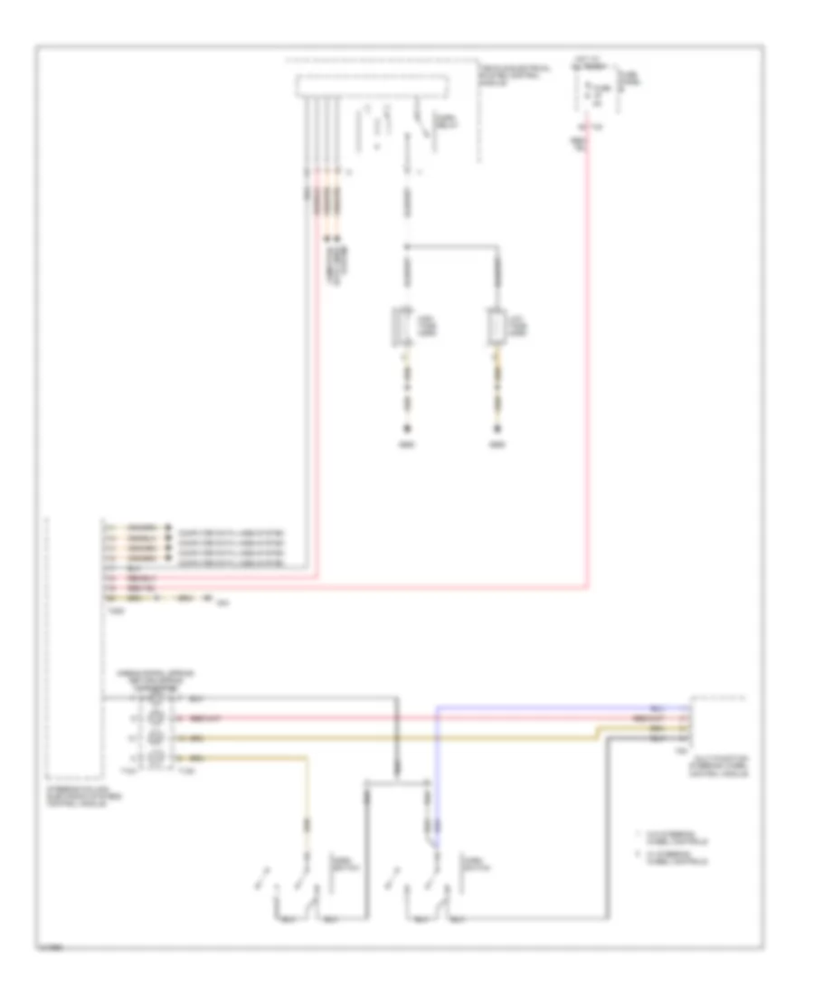
AIR CONDITIONING
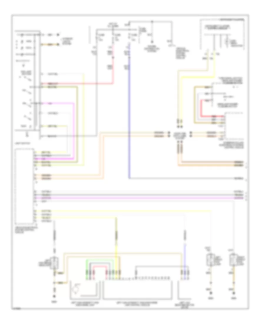
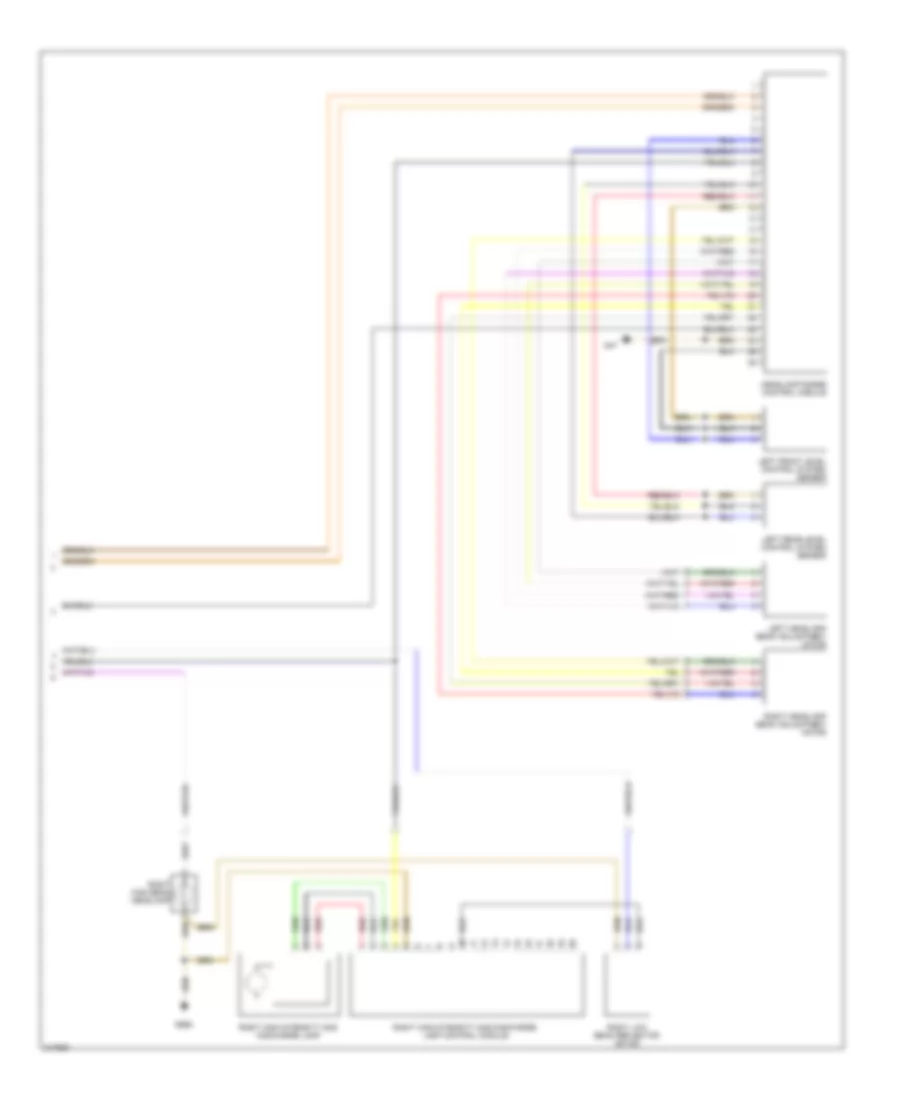
Heater Wiring Diagram for Volkswagen GTI 2006
 https://portal-diagnostov.com/license.html
Automotive Electricians Portal FZCO
Automotive Electricians Portal FZCO
https://portal-diagnostov.com/license.html
https://portal-diagnostov.com/license.html
Automotive Electricians Portal FZCO
Automotive Electricians Portal FZCO
List of elements for Heater Wiring Diagram for Volkswagen GTI 2006:
- (not used)
- 14a
- 40a
- Driver's heated seat adjuster
- Fresh air & recirculating air mode light
- Fresh air blower
- Fresh air blower series resistance (w/fuse)
- Fresh air blower switch
- Fresh air regulator light
- Fresh air/ recirculating flap switch
- Front passenger's heated seat adjuster
- Fuse 10a
- Fuse 5a
- Fuse panel c
- G47
- G602
- Heated rear window button
- Heater/heat output switch
- Hot at all times
- Hot w/ load reduction relay energized
- Interior lights system
- Rear window defogger light
- Regulator flap motor
- Seats system
- T20c
- Vehicle electrical system control module
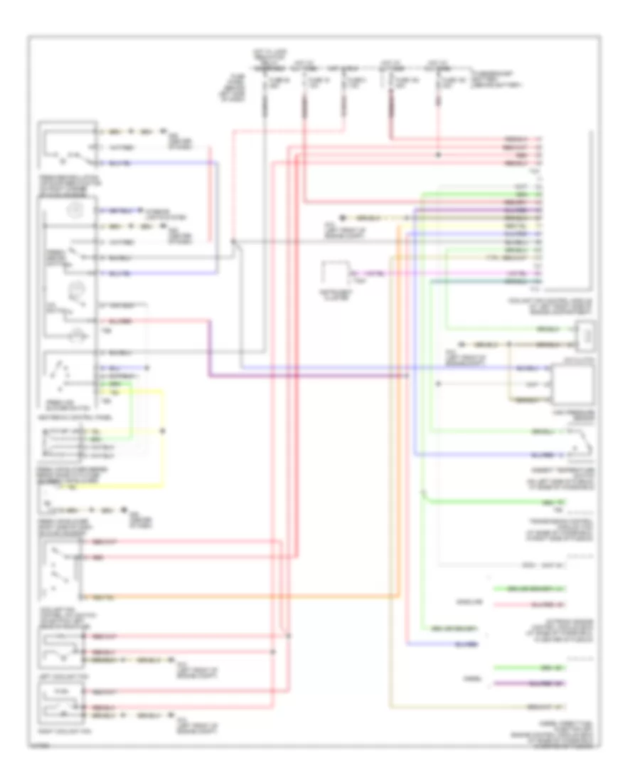
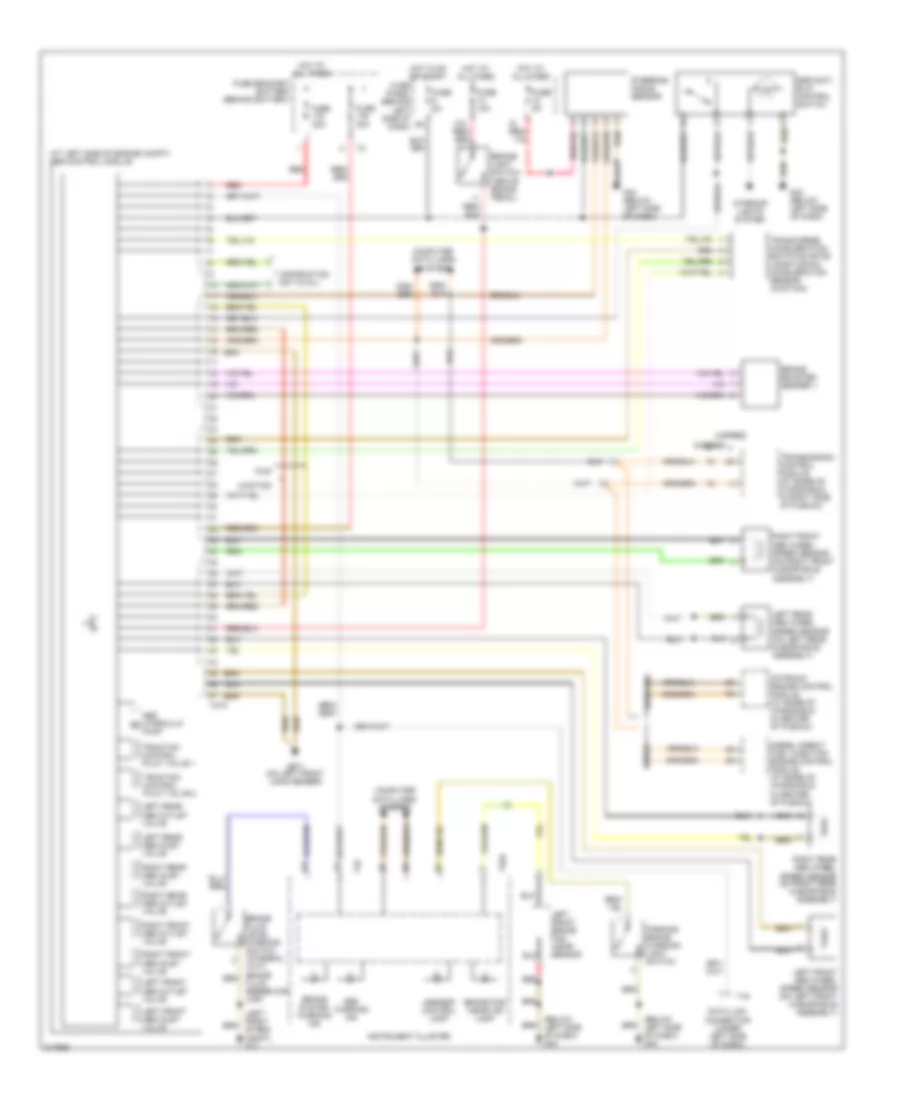
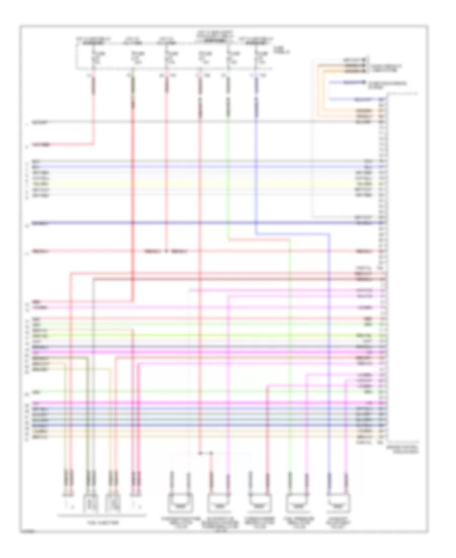
1.8L TURBO
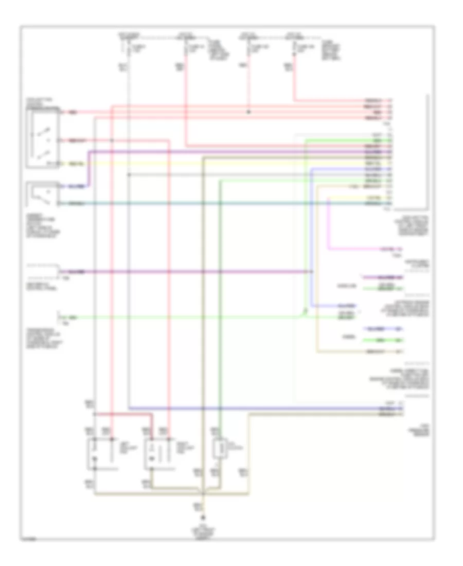
1.8L Turbo, Manual A/C Wiring Diagram for Volkswagen GTI 2006
 https://portal-diagnostov.com/license.html
Automotive Electricians Portal FZCO
Automotive Electricians Portal FZCO
https://portal-diagnostov.com/license.html
https://portal-diagnostov.com/license.html
Automotive Electricians Portal FZCO
Automotive Electricians Portal FZCOList of elements for 1.8L Turbo, Manual A/C Wiring Diagram for Volkswagen GTI 2006:
- (1.9l)
- (2.8l)
- A/c clutch
- A/c switch
- Ambient temperature switch (on left side of plenum, at base of windshield)
- Coolant fan control (fc) switch (on bottom left rear of radiator)
- Coolant fan control module (at left front side of engine compartment)
- Diesel
- Diesel direct fuel injection (dfi) engine control module (ecm) (at base of windshield in center of plenum)
- Fresh air blower (right side of dash, on hvac housing)
- Fresh air blower series resistance with fuse (on fresh air blower)
- Fresh air blower switch
- Fresh/ recirc switch
- Fresh/recirculating air door servo motor (on right corner of hvac housing)
- Fuse 16 10a
- Fuse 164 40a
- Fuse 180 30a
- Fuse 25 25a
- Fuse 5 7.5a
- Fuse panel (behind left side of dash)
- Fuse/bracket battery (behind battery)
- G12 (left front of engine compt)
- G45 (center of dash)
- Gasoline
- Heater-a/c control panel
- High pressure sensor
- Hot at all times
- Hot in run
- Hot w/ load reduction relay energized
- Instrument cluster
- Interior lights system
- Left coolant fan
- Motronic engine control module (ecm) (at base of windshield, in center of plenum)
- Red
- Right coolant fan
- T14
- T32a
- T4a
- T68
- T6d
- T8b
- Transmission control module (tcm) (at base of windshield, in right side of plenum)
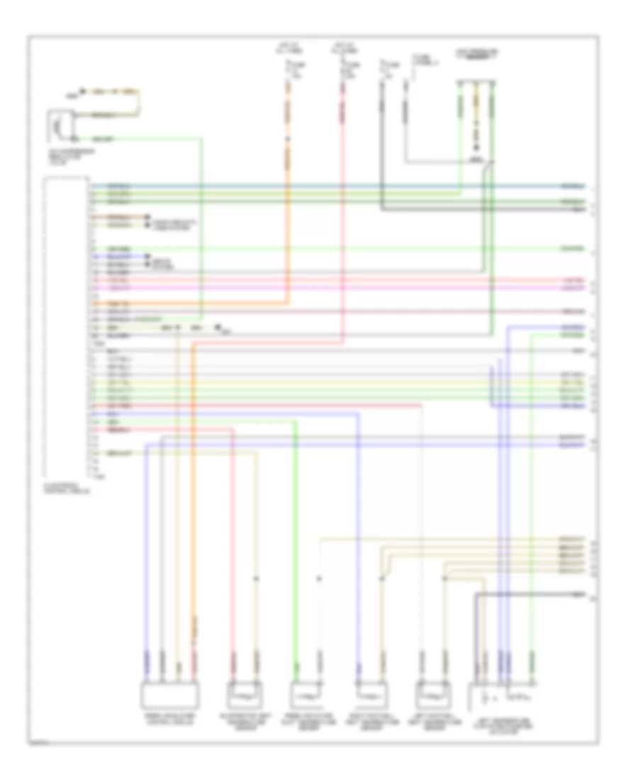
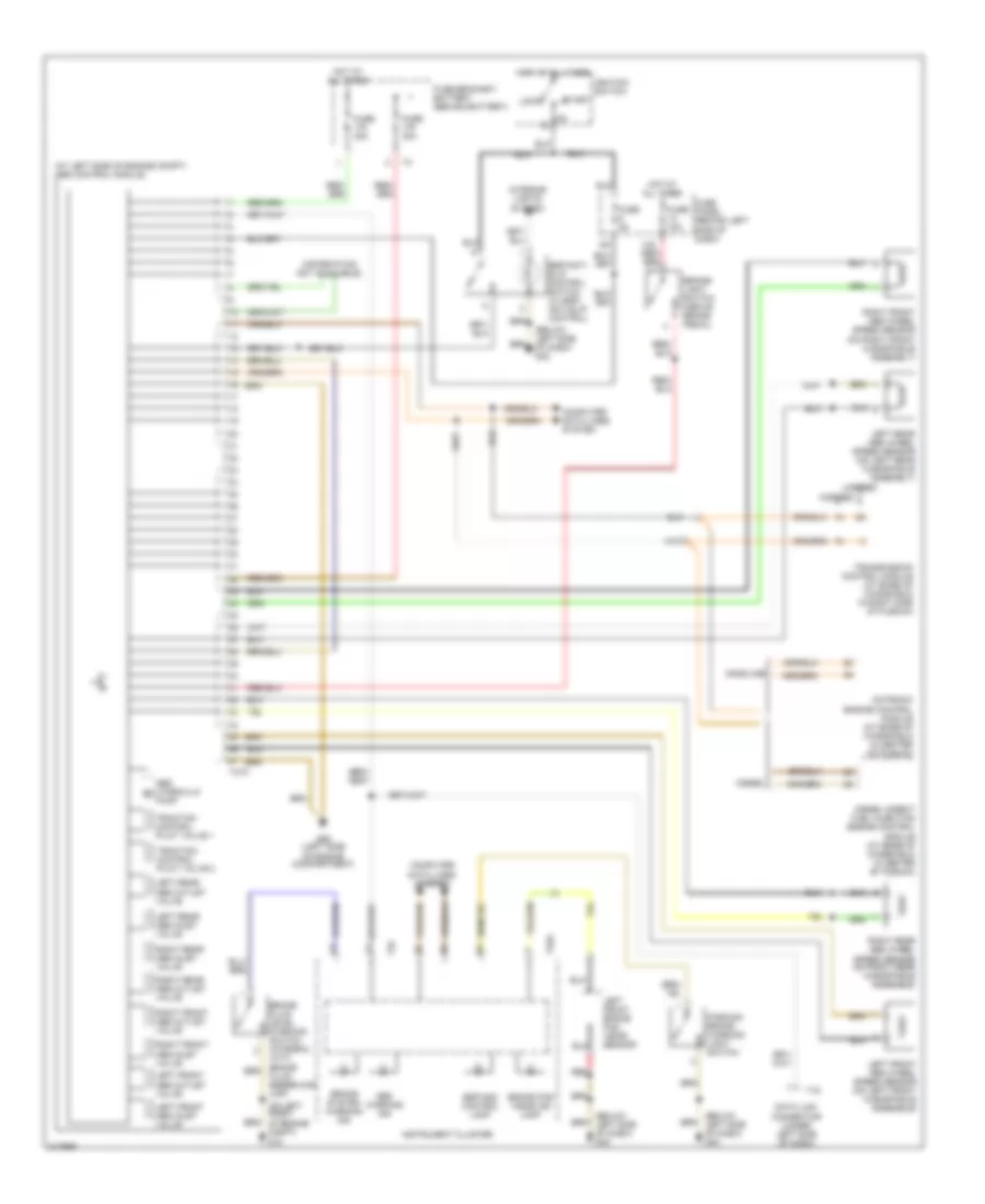
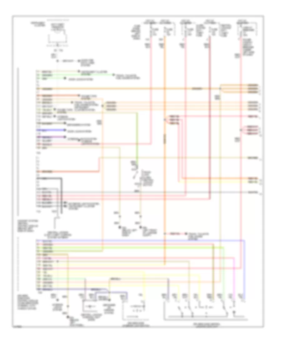
2.0L
2.0L, Automatic A/C Wiring Diagram, with Climatronic (1 of 3) for Volkswagen GTI 2006
 https://portal-diagnostov.com/license.html
Automotive Electricians Portal FZCO
Automotive Electricians Portal FZCO
https://portal-diagnostov.com/license.html
https://portal-diagnostov.com/license.html
Automotive Electricians Portal FZCO
Automotive Electricians Portal FZCOList of elements for 2.0L, Automatic A/C Wiring Diagram, with Climatronic (1 of 3) for Volkswagen GTI 2006:
- 14a
- 22a
- A/c compressor regulator valve
- Climatronic control module
- Computer data lines system
- Evaporator vent temperature sensor
- Fresh air blower control module
- Fresh air intake duct temperature sensor
- Fuse 10a
- Fuse 40a
- Fuse 5a
- Fuse panel c
- G47
- G605
- G655
- High pressure sensor
- Hot at all times
- Left footwell vent temperature sensor
- Left temperature flap potentiometer/ actuator
- Right footwell vent temperature sensor
- Seats system
- T16c
- T20c
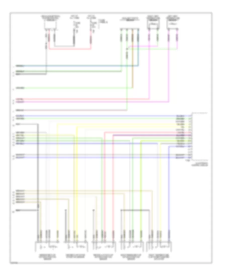
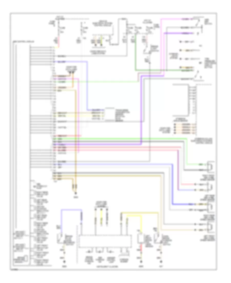
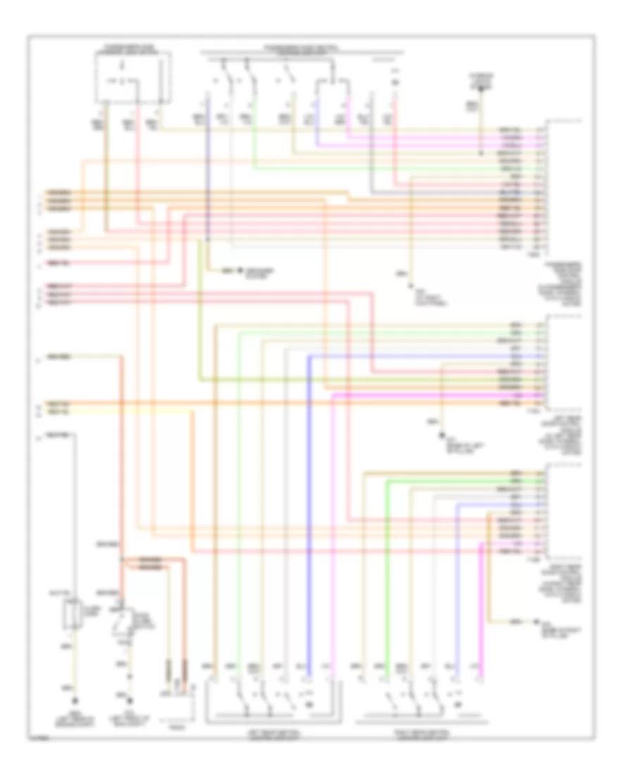
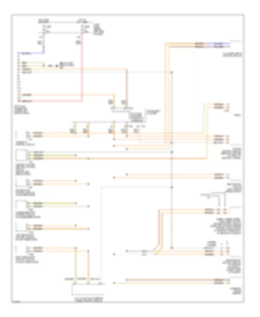
2.0L, Automatic A/C Wiring Diagram, with Climatronic (2 of 3) for Volkswagen GTI 2006
 https://portal-diagnostov.com/license.html
Automotive Electricians Portal FZCO
Automotive Electricians Portal FZCO
https://portal-diagnostov.com/license.html
https://portal-diagnostov.com/license.html
Automotive Electricians Portal FZCO
Automotive Electricians Portal FZCOList of elements for 2.0L, Automatic A/C Wiring Diagram, with Climatronic (2 of 3) for Volkswagen GTI 2006:
- Back pressure flap motor & position sensor
- Center flap motor & position sensor
- Climatronic control module
- Defroster flap motor & position sensor
- Fuse 40a
- Fuse panel b
- Hot at all times
- Left vent temperature sensor
- Recirculation flap motor & position sensor
- Right temperature flap potentiometer/ actuator
- Right vent temperature sensor
- Sunlight photo sensor
- T16d
- T40
- Vehicle electrical system control module
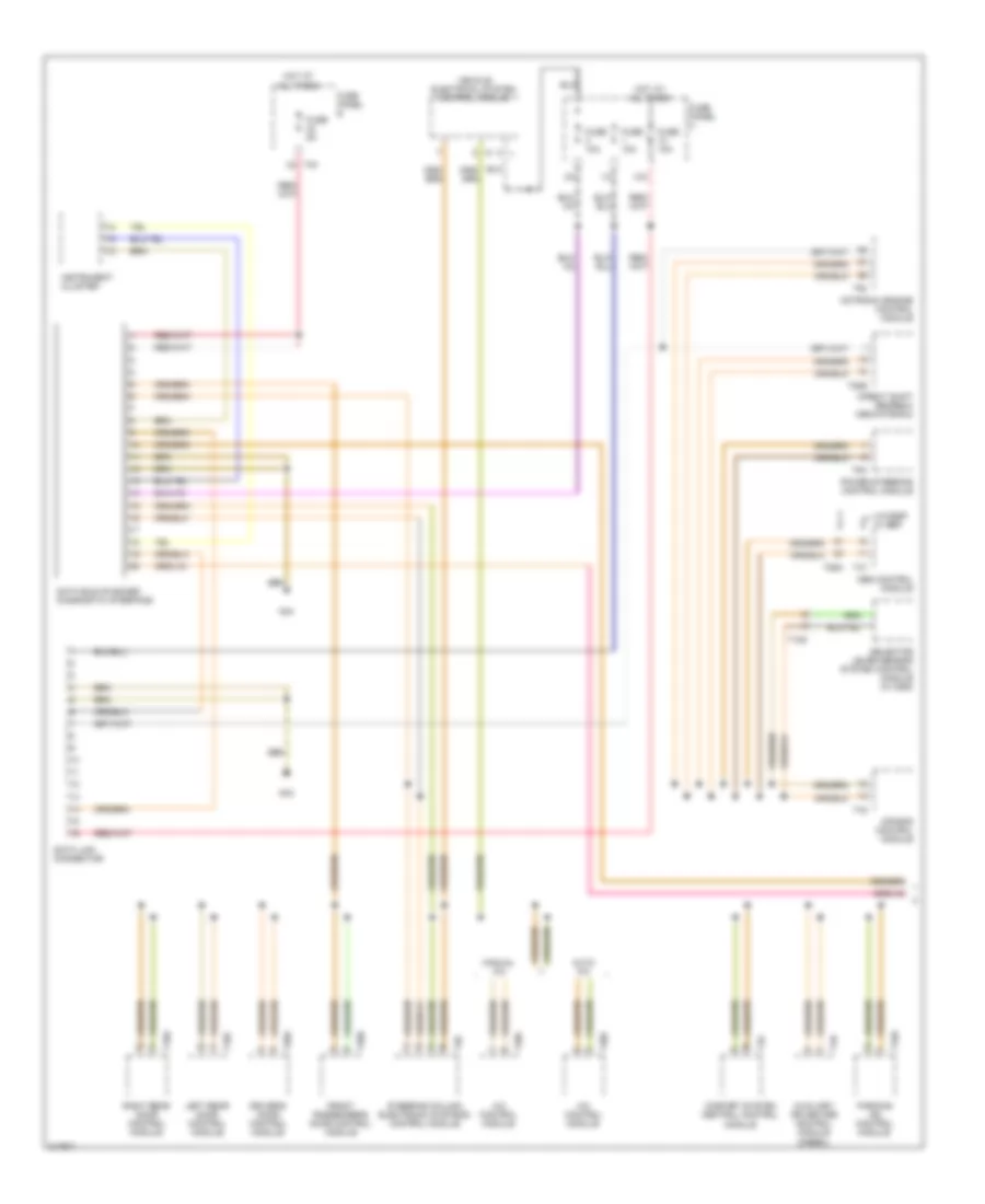
2.0L, Automatic A/C Wiring Diagram, with Climatronic (3 of 3) for Volkswagen GTI 2006
 https://portal-diagnostov.com/license.html
Automotive Electricians Portal FZCO
Automotive Electricians Portal FZCO
https://portal-diagnostov.com/license.html
https://portal-diagnostov.com/license.html
Automotive Electricians Portal FZCO
Automotive Electricians Portal FZCOList of elements for 2.0L, Automatic A/C Wiring Diagram, with Climatronic (3 of 3) for Volkswagen GTI 2006:
- After-run coolant pump
- Auxiliary engine coolant pump relay
- Coolant fan 2
- Coolant fan control (fc) control module
- Engine control module (ecm)
- Engine coolant temperature sensor (on radiator)
- Fuse 10a
- Fuse 50a
- Fuse panel a
- Fuse/ relay panel
- G607
- G642
- Hot at all times
- Nca
- Red
- T26
- T2v
- T40
- T4x
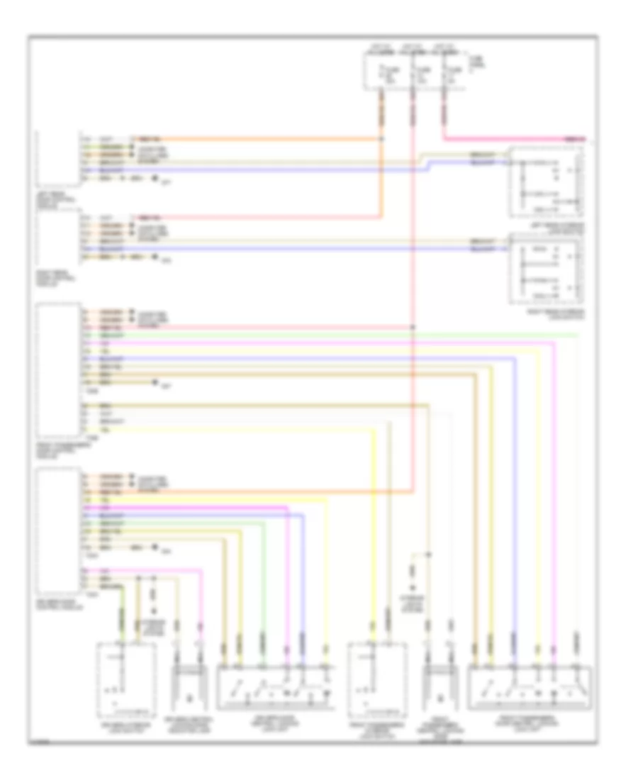
2.0L, Automatic A/C Wiring Diagram, without Climatronic for Volkswagen GTI 2006
 https://portal-diagnostov.com/license.html
Automotive Electricians Portal FZCO
Automotive Electricians Portal FZCO
https://portal-diagnostov.com/license.html
https://portal-diagnostov.com/license.html
Automotive Electricians Portal FZCO
Automotive Electricians Portal FZCOList of elements for 2.0L, Automatic A/C Wiring Diagram, without Climatronic for Volkswagen GTI 2006:
- 14a
- 40a
- A/c compressor regulator valve
- A/c control module
- A/c switch
- A/c warning light
- Center outlet temperature sensor
- Computer data lines system
- Driver's heated seat adjuster
- Evaporator vent temperature sensor
- Footwell outlet temperature sensor
- Fresh air & recirculating air mode light
- Fresh air blower
- Fresh air blower series resistance (w/fuse)
- Fresh air blower switch
- Fresh air regulator light
- Fresh air/ recirculating flap switch
- Front passenger's heated seat adjuster
- Fuse 10a
- Fuse 5a
- Fuse panel c
- G47
- G602
- G605
- G655
- Heated rear window button
- High pressure sensor
- Hot at all times
- Hot w/ load reduction relay energized
- Rear window defogger light
- Recirculation flap motor
- Seats system
- T16e
- T20c
- Temp selector knob potentiometer
- Temperature regulator flap motor & potentionmeter/ actuator
ANTI-LOCK BRAKES
Anti-lock Brakes Wiring Diagram, Early Production with ESP for Volkswagen GTI 2006
 https://portal-diagnostov.com/license.html
Automotive Electricians Portal FZCO
Automotive Electricians Portal FZCO
https://portal-diagnostov.com/license.html
https://portal-diagnostov.com/license.html
Automotive Electricians Portal FZCO
Automotive Electricians Portal FZCOList of elements for Anti-lock Brakes Wiring Diagram, Early Production with ESP for Volkswagen GTI 2006:
- (at left side of engine compt) abs control module
- (below left side of dash) g42
- (information not avail)
- 13a
- 4-motion
- 4-speed
- 5-speed
- Abs hydraulic pump
- Abs warning ind
- Asr/esp control lamp
- Brake booster sender 1
- Brake fluid level warning switch (integral with brake fluid reservoir cap)
- Brake pad wear ind lamp
- Brake system warning ind
- Brake- light switch (above brake pedal)
- Compt) g12
- Computer data lines system
- Data link connector (under left side of dash)
- Diesel
- Diesel direct fuel injection engine control module (at base of windshield in center of plenum)
- Esp/anti- slip control switch
- Fuse 10a
- Fuse 30a
- Fuse 5a
- Fuse bracket/ battery (behind battery)
- Fuse panel (behind left side of 9a dash)
- Fwd
- G42 (below left side of dash)
- G671 (on left front long member)
- Gasoline
- Hot at all times
- Hot in on or start
- Instrument cluster
- Interior lights system
- Left front abs inlet valve
- Left front abs outlet valve
- Left front abs wheel speed sensor (on left front hub/spindle assembly)
- Left front brake pad wear sensor
- Left rear abs inlet valve
- Left rear abs outlet valve
- Left rear abs wheel speed sensor (on left rear hub/spindle assembly)
- Motronic engine control module (at base of windshield in center of plenum)
- Parking brake warning light switch
- Red
- Right front abs inlet valve
- Right front abs outlet valve
- Right front abs wheel speed sensor (on right front hub/spindle assembly)
- Right rear abs inlet valve
- Right rear abs outlet valve
- Right rear abs wheel speed sensor (on right rear hub/spindle assembly)
- Steering angle sensor
- T16
- T32
- T32a
- T47a
- Traction control pilot valve 1
- Traction control pilot valve 2
- Transmission control module (at base of windshield in right side of plenum)
- Transverse acceleration/ rotation rate/ longitudinal acceleration sensor (4-motion)
Anti-lock Brakes Wiring Diagram, Early Production without ESP for Volkswagen GTI 2006
 https://portal-diagnostov.com/license.html
Automotive Electricians Portal FZCO
Automotive Electricians Portal FZCO
https://portal-diagnostov.com/license.html
https://portal-diagnostov.com/license.html
Automotive Electricians Portal FZCO
Automotive Electricians Portal FZCOList of elements for Anti-lock Brakes Wiring Diagram, Early Production without ESP for Volkswagen GTI 2006:
- (at left side of engine compt) abs control module
- (below left side of dash) g42
- (information not available)
- (on left front of engine compt)
- 13a
- 4-speed
- 5-speed
- Abs hydraulic pump
- Abs warning ind
- Brake fluid level warning switch (integral with brake fluid reservoir cap)
- Brake pad wear ind lamp
- Brake system warning ind
- Brake- light switch (above brake pedal)
- Computer data lines system
- Data link connector (under left side of dash)
- Diesel
- Diesel direct fuel injection engine control module (at base of windshield in center of plenum)
- Esp/anti- slip control switch (w/ esp/ anti-slip control)
- Esp/asc control lamp
- Fuse 10a
- Fuse 30a
- Fuse 5a
- Fuse bracket/ battery (behind battery)
- Fuse panel (behind left side of dash)
- G12
- G65 (left side of engine compartment)
- Gasoline
- Hot at all times
- Ignition switch
- Instrument cluster
- Interior lights system
- Left front abs inlet valve
- Left front abs outlet valve
- Left front abs wheel speed sensor (on left front hub/spindle assemble)
- Left front brake pad wear sensor
- Left rear abs inlet valve
- Left rear abs outlet valve
- Left rear abs wheel speed sensor (on left rear hub/spindle assembly)
- Lock
- Motronic engine control module (at base of windshield in center of plenum)
- Parking brake warning light switch
- Red
- Right front abs inlet valve
- Right front abs outlet valve
- Right front abs wheel speed sensor (on right front hub/spindle assembly)
- Right rear abs inlet valve
- Right rear abs outlet valve
- Right rear abs wheel speed sensor (on right rear hub/spindle assemble)
- Start
- T16
- T32
- T32a
- T47a
- Traction control pilot valve 1
- Traction control pilot valve 2
- Transmission control module (at base of windshield in right side of plenum)
Anti-lock Brakes Wiring Diagram, Late Production with ESP for Volkswagen GTI 2006
 https://portal-diagnostov.com/license.html
Automotive Electricians Portal FZCO
Automotive Electricians Portal FZCO
https://portal-diagnostov.com/license.html
https://portal-diagnostov.com/license.html
Automotive Electricians Portal FZCO
Automotive Electricians Portal FZCOList of elements for Anti-lock Brakes Wiring Diagram, Late Production with ESP for Volkswagen GTI 2006:
- 13a
- Abs control module
- Abs hydraulic pump
- Abs warning ind
- Asr/ esp switch
- Asr/esp control lamp
- Brake fluid level warning switch
- Brake pressure sensor 1
- Brake system warning ind
- Brake- light switch
- Computer data lines system
- Driving dynamics reg hp sw vlv 1
- Driving dynamics reg hp sw vlv 2
- Driving dynamics regulation sw vlv 1
- Fuse 10a
- Fuse 30a
- Fuse 5a
- Fuse panel b
- Fuse panel c
- G47
- G605
- G638
- G655
- Hand- brake warning light switch
- Hot at all times
- Instrument cluster
- Interior lights system
- Left front abs inlet valve
- Left front abs outlet valve
- Left front abs wheel speed sensor
- Left front brake pad wear sensor
- Left rear abs inlet valve
- Left rear abs outlet valve
- Left rear abs wheel speed sensor
- Red
- Right front abs inlet valve
- Right front abs outlet valve
- Right front abs wheel speed sensor
- Right rear abs inlet valve driving dynamics regulation sw vlv 2
- Right rear abs outlet valve
- Right rear abs wheel speed sensor
- Steering angle sensor
- Steering column electronic systems control module
- T40
- T47
- Tire pressure monitoring display button
- Transverse acceleration sensor/ rotation rate sensor
- Vehicle electrical system control module
- Warning buzzer
Anti-lock Brakes Wiring Diagram, Late Production without ESP for Volkswagen GTI 2006
 https://portal-diagnostov.com/license.html
Automotive Electricians Portal FZCO
Automotive Electricians Portal FZCO
https://portal-diagnostov.com/license.html
https://portal-diagnostov.com/license.html
Automotive Electricians Portal FZCO
Automotive Electricians Portal FZCOList of elements for Anti-lock Brakes Wiring Diagram, Late Production without ESP for Volkswagen GTI 2006:
- 13a
- Abs control module
- Abs hydraulic pump
- Abs warning ind
- Asr/ esp switch
- Asr/esp control lamp
- Brake fluid level warning switch
- Brake system warning ind
- Brake- light switch
- Computer data lines system
- Driving dynamics regulation sw vlv 1
- Driving dynamics regulation sw vlv 2
- Fuse 10a
- Fuse 30a
- Fuse 5a
- Fuse panel b
- Fuse panel c
- G47
- G605
- G638
- G655
- Hand- brake warning light switch
- Hot at all times
- Instrument cluster
- Interior lights system
- Left front abs inlet valve
- Left front abs outlet valve
- Left front abs wheel speed sensor
- Left front brake pad wear sensor
- Left rear abs inlet valve
- Left rear abs outlet valve
- Left rear abs wheel speed sensor
- Red
- Right front abs inlet valve
- Right front abs outlet valve
- Right front abs wheel speed sensor
- Right rear abs inlet valve
- Right rear abs outlet valve
- Right rear abs wheel speed sensor
- T26a
- T40
- Tire pressure monitoring display button
- Vehicle electrical system control module
- Warning buzzer
ANTI-THEFT
Anti-theft Wiring Diagram, Early Production (1 of 2) for Volkswagen GTI 2006
 https://portal-diagnostov.com/license.html
Automotive Electricians Portal FZCO
Automotive Electricians Portal FZCO
https://portal-diagnostov.com/license.html
https://portal-diagnostov.com/license.html
Automotive Electricians Portal FZCO
Automotive Electricians Portal FZCOList of elements for Anti-theft Wiring Diagram, Early Production (1 of 2) for Volkswagen GTI 2006:
- 14a
- 38a
- Alarm system anti- theft fuse
- Anti-theft indicator
- Central locking & anti-theft warning system antenna
- Central locking warning light (safe)
- Central locking/ anti- theft fuse
- Circuit breaker 30a
- Comfort system central control module (behind left side of dash)
- Computer data lines system
- Defogger or mirrors system
- Defoggers system
- Door locks system
- Driver's side central locking lock unit
- Driver's side door control module (in driver's door, integral with window motor)
- Driver's side interior lock switch
- Exterior lights system, instrument cluster system
- Fuse 10a
- Fuse 15a
- Fuse panel (behind left side of dash)
- G42 (below left side of dash)
- G44 (behind left kick panel)
- G50 (left front of luggage compt)
- Hot at all times
- Instrument cluster
- Instrument cluster system
- Interior lights system
- Nca
- Power tops system
- Power window circuit breaker (under left side of dash)
- T15
- T23
- T29
- T32
- Trunk lock alarm/ central locking switch
- Trunk, tailgate fuel doors system
- Trunk, tailgate, fuel doors system
- Trunk, tailgate, fuel doors system instrument cluster system
Anti-theft Wiring Diagram, Early Production (2 of 2) for Volkswagen GTI 2006
 https://portal-diagnostov.com/license.html
Automotive Electricians Portal FZCO
Automotive Electricians Portal FZCO
https://portal-diagnostov.com/license.html
https://portal-diagnostov.com/license.html
Automotive Electricians Portal FZCO
Automotive Electricians Portal FZCOList of elements for Anti-theft Wiring Diagram, Early Production (2 of 2) for Volkswagen GTI 2006:
- Alarm horn
- Defogger system
- G12 (left front of eng compt)
- G43 (at right kick panel)
- G608 (left rear of engine compt)
- G77 (base of left "b" pillar)
- G78 (base of right "b" pillar)
- Hood alarm switch
- Interior lights system
- Left rear central locking lock unit
- Left rear door control module (in left rear door, integral with window motor)
- Nca
- Passenger's side central locking lock unit
- Passenger's side door control module (in passenger's door, integral with window motor)
- Passenger's side interior lock switch
- Radio
- Right rear central locking lock unit
- Right rear door control module (in right rear door, integral with window motor)
- T16d
- T18a
- T18b
- T29a
Anti-theft Wiring Diagram, Late Production (1 of 2) for Volkswagen GTI 2006
 https://portal-diagnostov.com/license.html
Automotive Electricians Portal FZCO
Automotive Electricians Portal FZCO
https://portal-diagnostov.com/license.html
https://portal-diagnostov.com/license.html
Automotive Electricians Portal FZCO
Automotive Electricians Portal FZCOList of elements for Anti-theft Wiring Diagram, Late Production (1 of 2) for Volkswagen GTI 2006:
- 12a
- 17a
- 26a
- Computer data lines system
- Driver's central locking safe indicator lamp
- Driver's door central locking lock unit
- Driver's door control module
- Driver's interior lock switch
- Front passenger's central locking safe indicator lamp
- Front passenger's door central locking lock unit
- Front passenger's door control module
- Front passenger's interior lock switch
- Fuse 10a
- Fuse 30a
- Fuse 5a
- Fuse panel c
- G44
- G47
- G77
- G78
- Hot at all times
- Interior lights system
- Left rear door control module
- Left rear interior lock switch
- Nca
- Right rear door control module
- Right rear interior lock switch
- T20a
- T20b
- T32a
- T32b
Anti-theft Wiring Diagram, Late Production (2 of 2) for Volkswagen GTI 2006
 https://portal-diagnostov.com/license.html
Automotive Electricians Portal FZCO
Automotive Electricians Portal FZCO
https://portal-diagnostov.com/license.html
https://portal-diagnostov.com/license.html
Automotive Electricians Portal FZCO
Automotive Electricians Portal FZCOList of elements for Anti-theft Wiring Diagram, Late Production (2 of 2) for Volkswagen GTI 2006:
- (not used)
- Alarm horn
- Alarm horn relay (w/ display & multifunction control)
- Central locking & anti-theft alarm system antenna
- Comfort system central control module
- Computer data lines system
- Front hood switch
- Fuse 20a
- Fuse panel b
- G47
- G656
- G679
- G77
- G78
- Hot at all times
- Interior lights system
- Left rear central locking lock unit
- Nca
- Power tops system
- Rear lid handle unlcok switch
- Rear lid lock unit
- Right rear central locking lock unit
- T18
- T18a
- T40
- T8n
- Trunk, tailgate, fuel doors system
- Vehicle electrical system control module
- W/ alarm horn relay
- W/o alarm horn relay
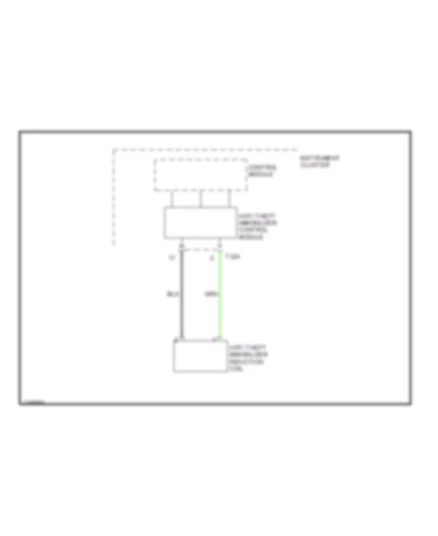
Immobilizer Wiring Diagram for Volkswagen GTI 2006
 https://portal-diagnostov.com/license.html
Automotive Electricians Portal FZCO
Automotive Electricians Portal FZCO
https://portal-diagnostov.com/license.html
https://portal-diagnostov.com/license.html
Automotive Electricians Portal FZCO
Automotive Electricians Portal FZCOList of elements for Immobilizer Wiring Diagram for Volkswagen GTI 2006:
- Anti theft immobilizer control module
- Anti theft immobilizer induction coil
- Control module
- Instrument cluster
- T32a
BODY CONTROL MODULES
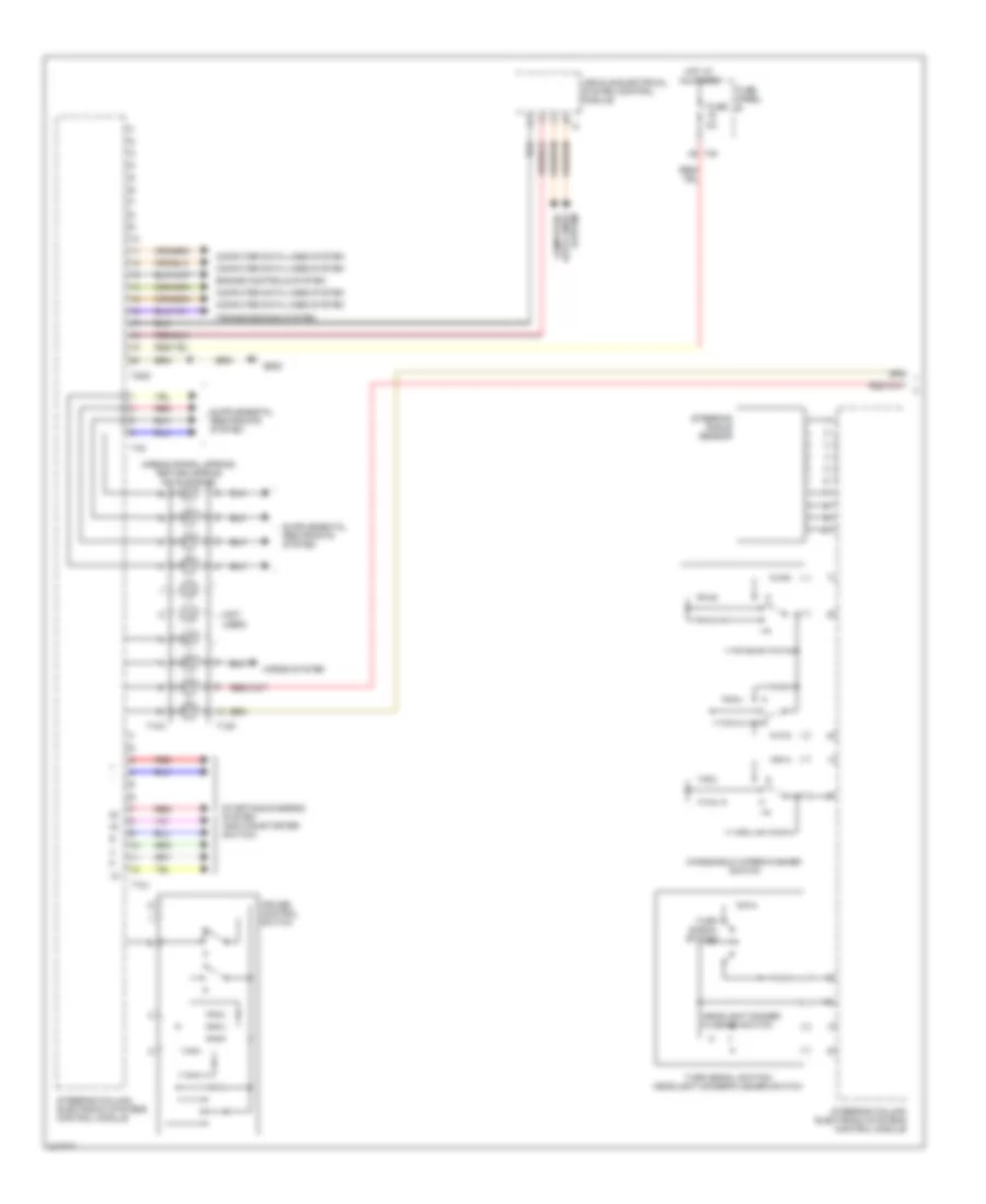
Steering Column Electronic Systems Control Module Wiring Diagram (1 of 2) for Volkswagen GTI 2006
 https://portal-diagnostov.com/license.html
Automotive Electricians Portal FZCO
Automotive Electricians Portal FZCO
https://portal-diagnostov.com/license.html
https://portal-diagnostov.com/license.html
Automotive Electricians Portal FZCO
Automotive Electricians Portal FZCOList of elements for Steering Column Electronic Systems Control Module Wiring Diagram (1 of 2) for Volkswagen GTI 2006:
- (not used)
- Airbag spiral spring/ return spring (w/ slip ring)
- Computer data lines system
- Cruise control switch
- Engine controls system
- Fuse 5a
- Fuse panel b
- G605
- Headlight dimmer/ flasher switch
- Horns system
- Hot at all times
- Red
- Starting/charging system (ignition/starter switch)
- Steering angle sensor
- Steering column electronic systems control module
- T10x
- T12j
- T12k
- T20d
- T40
- T4k
- Transmissions system
- Turn signal switch
- Turn signal switch/ headlight dimmer/flasher switch
- Vehicle electrical system control module
- Windshield wiper/washer switch
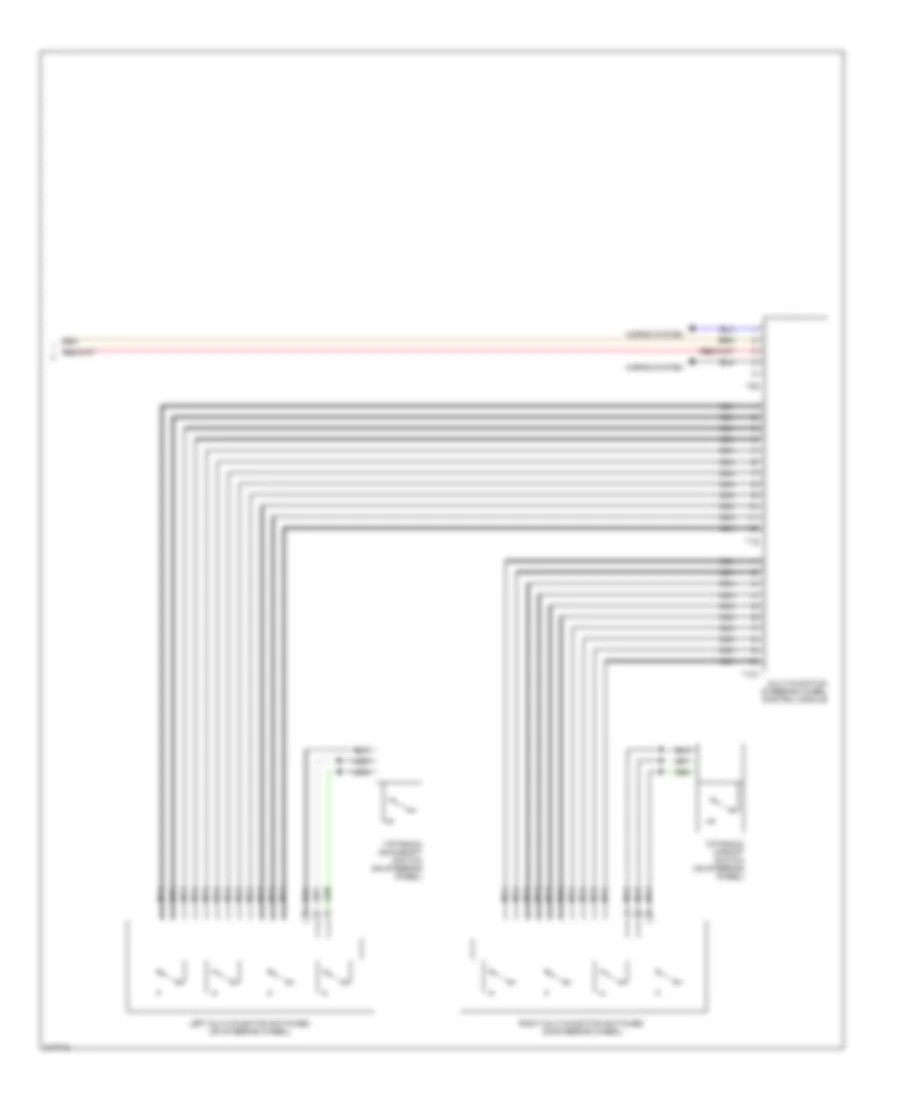
Steering Column Electronic Systems Control Module Wiring Diagram (2 of 2) for Volkswagen GTI 2006
 https://portal-diagnostov.com/license.html
Automotive Electricians Portal FZCO
Automotive Electricians Portal FZCO
https://portal-diagnostov.com/license.html
https://portal-diagnostov.com/license.html
Automotive Electricians Portal FZCO
Automotive Electricians Portal FZCOList of elements for Steering Column Electronic Systems Control Module Wiring Diagram (2 of 2) for Volkswagen GTI 2006:
- Horns system
- Left multi-function switches (on steering wheel)
- Multi-function steering wheel control module
- Nca
- Right multi-function switches (on steering wheel)
- T10y
- T12i
- T5k
- Tiptronic downshift switch (on steering wheel)
- Tiptronic upshift switch (on steering wheel)
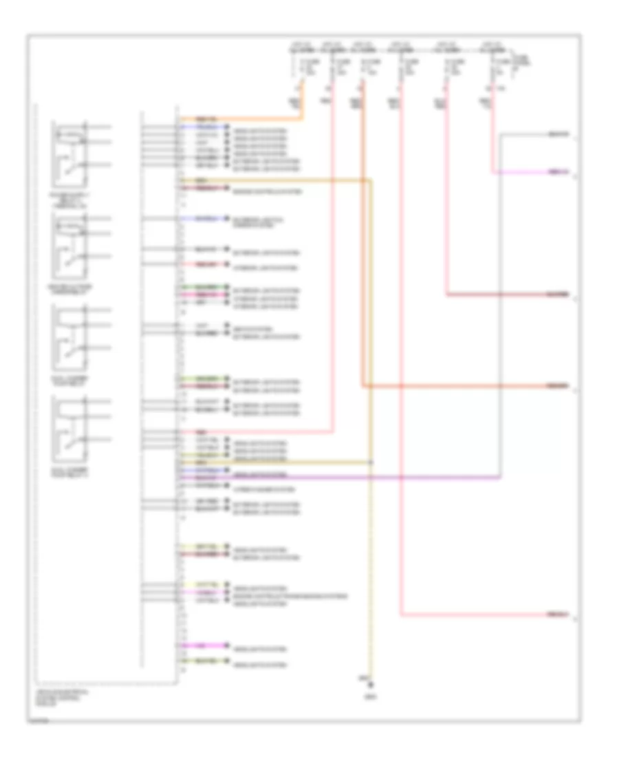
Vehicle Electrical System Control Module Wiring Diagram (1 of 2) for Volkswagen GTI 2006
 https://portal-diagnostov.com/license.html
Automotive Electricians Portal FZCO
Automotive Electricians Portal FZCO
https://portal-diagnostov.com/license.html
https://portal-diagnostov.com/license.html
Automotive Electricians Portal FZCO
Automotive Electricians Portal FZCOList of elements for Vehicle Electrical System Control Module Wiring Diagram (1 of 2) for Volkswagen GTI 2006:
- Dual washer pump relay
- Dual washer pump relay 2
- Engine controls system
- Engine controls/transmissions systems
- Exterior lights & mirror system
- Exterior lights system
- Fuse 15a
- Fuse 40a
- Fuse 5a
- Fuse panel b
- G605
- Headlights system
- Heated outside mirror relay
- Hot at all times
- Interior lights system
- Red
- Seats system
- T40
- Vehicle electrical system control module
- Wiper/washer system
Vehicle Electrical System Control Module Wiring Diagram (2 of 2) for Volkswagen GTI 2006
 https://portal-diagnostov.com/license.html
Automotive Electricians Portal FZCO
Automotive Electricians Portal FZCO
https://portal-diagnostov.com/license.html
https://portal-diagnostov.com/license.html
Automotive Electricians Portal FZCO
Automotive Electricians Portal FZCOList of elements for Vehicle Electrical System Control Module Wiring Diagram (2 of 2) for Volkswagen GTI 2006:
- 15a
- 25a
- A/c system
- Anti-theft system
- Computer data lines system
- Dual horn relay
- Exterior lights system
- Fuse 25a
- Fuse 7.5a
- Fuse panel c
- G47
- G605
- Horns system
- Hot at all times
- Interior lights
- Interior lights system
- Load reduction relay
- Power distribution system
- Rear window defogger relay
- Sound system
- Starting/charging system
- Steering column electronic systems control module
- T20d
- Vehicle electrical system control module
- Wiper/washer system
COMPUTER DATA LINES
Computer Data Lines Wiring Diagram, Early Production for Volkswagen GTI 2006
 https://portal-diagnostov.com/license.html
Automotive Electricians Portal FZCO
Automotive Electricians Portal FZCO
https://portal-diagnostov.com/license.html
https://portal-diagnostov.com/license.html
Automotive Electricians Portal FZCO
Automotive Electricians Portal FZCOList of elements for Computer Data Lines Wiring Diagram, Early Production for Volkswagen GTI 2006:
- (below left side of dash) g42
- 1.8l & 2.0l
- 1.9l
- 12a
- 4-speed
- 5-speed
- Abs control module (left side of engine compt)
- Air bag control module (beneath center of dash, on central tunnel)
- All-wheel drive control module
- Comfort system central control module (behind left side of dash)
- Data bus on board diagnostic interface
- Data link connector (under left side of dash)
- Diesel: diesel direct fuel injection (dfi) engine control module gasoline: motronic engine control module (ecm) (at base of windshield, in center of plenum)
- Driver door control module (in driver's door)
- Fuse 7.5a
- Fuse panel (behind left side of dash)
- Hot at all times
- Hot in on or start
- Instrument cluster
- Left rear door control module (in left rear door)
- Multi-function steering wheel control module
- Passenger door control module (in passenger's door)
- Radio
- Right rear door control module (in right rear door)
- Steering angle sensor
- T16d
- T18a
- T18b
- T23
- T29
- T29a
- T32
- T32a
- T42
- Telematic control module
- Transmission control module (at base of windshield, in right side of plenum)
Computer Data Lines Wiring Diagram, Late Production (1 of 2) for Volkswagen GTI 2006
 https://portal-diagnostov.com/license.html
Automotive Electricians Portal FZCO
Automotive Electricians Portal FZCO
https://portal-diagnostov.com/license.html
https://portal-diagnostov.com/license.html
Automotive Electricians Portal FZCO
Automotive Electricians Portal FZCOList of elements for Computer Data Lines Wiring Diagram, Late Production (1 of 2) for Volkswagen GTI 2006:
- 13a
- A/c control module
- Abs control module
- Air bag control module
- Auto a/c
- Auxiliary air heater control module (diesel)
- Comfort system central control module
- Data bus on board diagnostic interface
- Data link connector
- Direct shift gearbox mechatronic
- Driver's door control module
- Front passenger's door control module
- Fuse 10a
- Fuse 5a
- Fuse panel b
- Fuse panel c
- G43
- G44
- Hot at all times
- Instrument cluster
- Left rear door control module
- Manual a/c
- Motronic engine control module
- Parking aid control module
- Power steering control module
- Right rear door control module
- Selector lever sensor system control module (w/ dsg)
- Steering column electronic systems control module
- T10s
- T16h
- T18
- T18c
- T18d
- T20
- T20a
- T20b
- T20c
- T20e
- T26a
- T40
- T47
- T4h
- T5h
- T75
- T94
- Vehicle electrical system control module
- W/o esp w/ esp
Computer Data Lines Wiring Diagram, Late Production (2 of 2) for Volkswagen GTI 2006
 https://portal-diagnostov.com/license.html
Automotive Electricians Portal FZCO
Automotive Electricians Portal FZCO
https://portal-diagnostov.com/license.html
https://portal-diagnostov.com/license.html
Automotive Electricians Portal FZCO
Automotive Electricians Portal FZCOList of elements for Computer Data Lines Wiring Diagram, Late Production (2 of 2) for Volkswagen GTI 2006:
- Amplifier
- Compass magnetic field sensor
- Operating electronic & telephone control module
- Radio/ navigation display control module or radio
- Satellite radio
- T16b
- T18b
- T23
- T8a
COOLING FAN
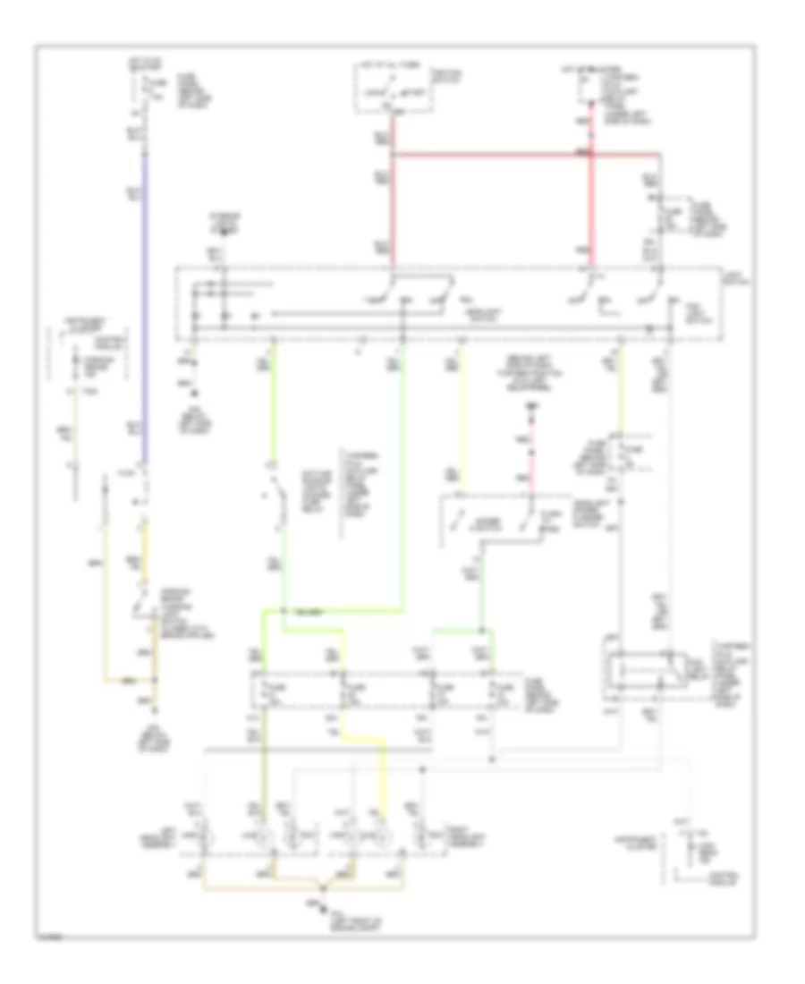
1.8L TURBO
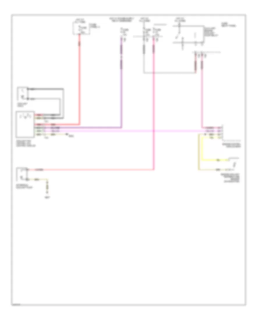
1.8L Turbo, Cooling Fan Wiring Diagram for Volkswagen GTI 2006
 https://portal-diagnostov.com/license.html
Automotive Electricians Portal FZCO
Automotive Electricians Portal FZCO
https://portal-diagnostov.com/license.html
https://portal-diagnostov.com/license.html
Automotive Electricians Portal FZCO
Automotive Electricians Portal FZCOList of elements for 1.8L Turbo, Cooling Fan Wiring Diagram for Volkswagen GTI 2006:
- (1.9l)
- A/c clutch
- Ambient temperature switch (left side of plenum, at base of windshield)
- Coolant fan control module (at left front side of engine compartment)
- Coolant fan control thermal switch
- Diesel
- Diesel direct fuel injection (dfi) engine control module (ecm) (at base of windshield in center of plenum)
- Fuse 16 10a
- Fuse 164 40a
- Fuse 180 30a
- Fuse 5 7.5a
- Fuse panel (behind left side of dash)
- Fuse/ bracket battery (behind battery)
- G12 (left front of engine compt)
- Gasoline
- Heater-a/c control panel
- High pressure sensor
- Hot at all times
- Hot in run & start
- Instrument cluster
- Left coolant fan
- Motronic engine control module (ecm) (at base of windshield, in center of plenum)
- Red
- Right coolant fan
- T14
- T32a
- T4a
- T68
- T8b
- Transmission control module (at base of windshield, right side of plenum)
2.0L
2.0L, Cooling Fan Wiring Diagram for Volkswagen GTI 2006
 https://portal-diagnostov.com/license.html
Automotive Electricians Portal FZCO
Automotive Electricians Portal FZCO
https://portal-diagnostov.com/license.html
https://portal-diagnostov.com/license.html
Automotive Electricians Portal FZCO
Automotive Electricians Portal FZCOList of elements for 2.0L, Cooling Fan Wiring Diagram for Volkswagen GTI 2006:
- After-run coolant pump
- Auxiliary engine coolant pump relay
- Coolant fan 2
- Coolant fan control (fc) control module
- Engine control module (ecm)
- Engine coolant temperature sensor (on radiator)
- Fuse 10a
- Fuse 50a
- Fuse panel a
- Fuse/ relay panel
- G607
- G642
- Hot at all times
- Nca
- Red
- T26
- T2v
- T40
- T4x
CRUISE CONTROL
1.8L TURBO
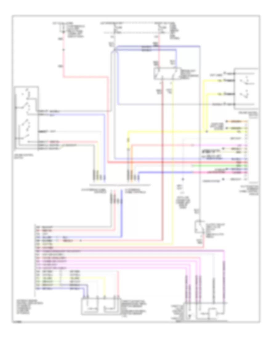
1.8L Turbo, Cruise Control Wiring Diagram for Volkswagen GTI 2006
 https://portal-diagnostov.com/license.html
Automotive Electricians Portal FZCO
Automotive Electricians Portal FZCO
https://portal-diagnostov.com/license.html
https://portal-diagnostov.com/license.html
Automotive Electricians Portal FZCO
Automotive Electricians Portal FZCOList of elements for 1.8L Turbo, Cruise Control Wiring Diagram for Volkswagen GTI 2006:
- (below left side of dash)
- (not used)
- 13a
- Brakelight switch (above brake pedal)
- Clutch vacuum vent valve switch (m/t) (above clutch pedal)
- Computer data lines system
- Cruise control switch
- Data link connector (under left side of dash)
- Fuse 10a
- Fuse 7.5a
- Fuse panel (behind left side of dash)
- G42
- Horns system
- Hot at all times
- Hot in on or start
- Interior lights system
- Motronic engine control module (ecm) (at base of windshield, in center of plenum)
- Multifunction steering wheel control module
- Nca
- Red
- Thirteenfold auxiliary relay panel (under left side of dash)
- Throttle position sensor/accel pedal position sensor (2.0l) accelerator pedal position sensor (1.8l)
- Throttle valve control module (on throttle body)
- W/ steering wheel controls
- W/o steering wheel controls
2.0L
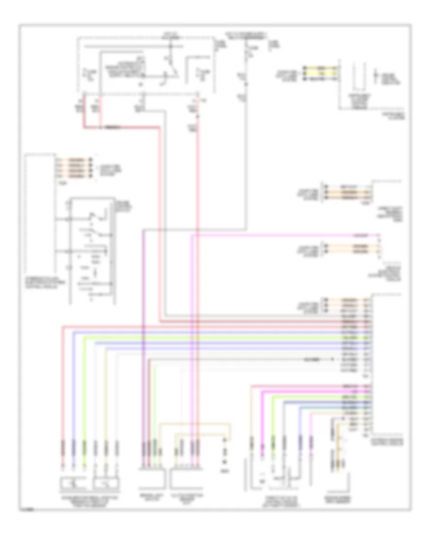
2.0L, Cruise Control Wiring Diagram for Volkswagen GTI 2006
 https://portal-diagnostov.com/license.html
Automotive Electricians Portal FZCO
Automotive Electricians Portal FZCO
https://portal-diagnostov.com/license.html
https://portal-diagnostov.com/license.html
Automotive Electricians Portal FZCO
Automotive Electricians Portal FZCOList of elements for 2.0L, Cruise Control Wiring Diagram for Volkswagen GTI 2006:
- Accelerator pedal position sensor 2/throttle position sensor
- Brake light switch
- Clutch position sensor (m/t)
- Computer data lines system
- Cruise control indicator
- Cruise control switch
- Direct shift gearbox mechatronic (dsg)
- Engine speed (rpm) sensor
- Fuse 10a
- Fuse 5a
- Fuse panel b
- Fuse panel c
- G605
- Hot at all times
- Instrument cluster
- Instrument cluster control module
- Motronic engine control module
- Steering column electronic systems control module
- T20d
- T20e
- T40
- T60
- T94
- Throttle valve control module (on throttle body)
- Vehicle electrical system control module
DEFOGGERS
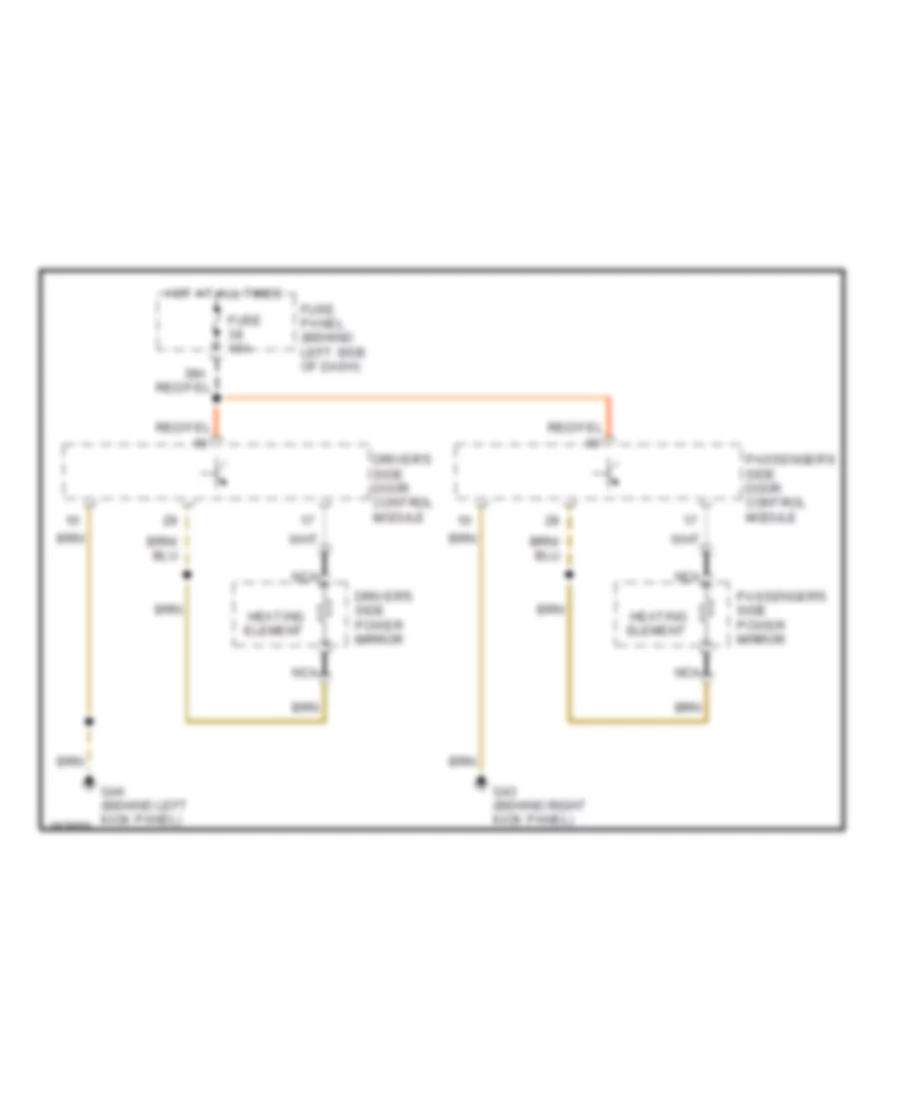
Heated Mirrors Wiring Diagram, Early Production for Volkswagen GTI 2006
 https://portal-diagnostov.com/license.html
Automotive Electricians Portal FZCO
Automotive Electricians Portal FZCO
https://portal-diagnostov.com/license.html
https://portal-diagnostov.com/license.html
Automotive Electricians Portal FZCO
Automotive Electricians Portal FZCOList of elements for Heated Mirrors Wiring Diagram, Early Production for Volkswagen GTI 2006:
- Driver's side door control module
- Driver's side power mirror
- Fuse 15a
- Fuse panel (behind left side of dash)
- G43 (behind right kick panel)
- G44 (behind left kick panel)
- Heating element
- Hot at all times
- Nca
- Passenger's side door control module
- Passenger's side power mirror
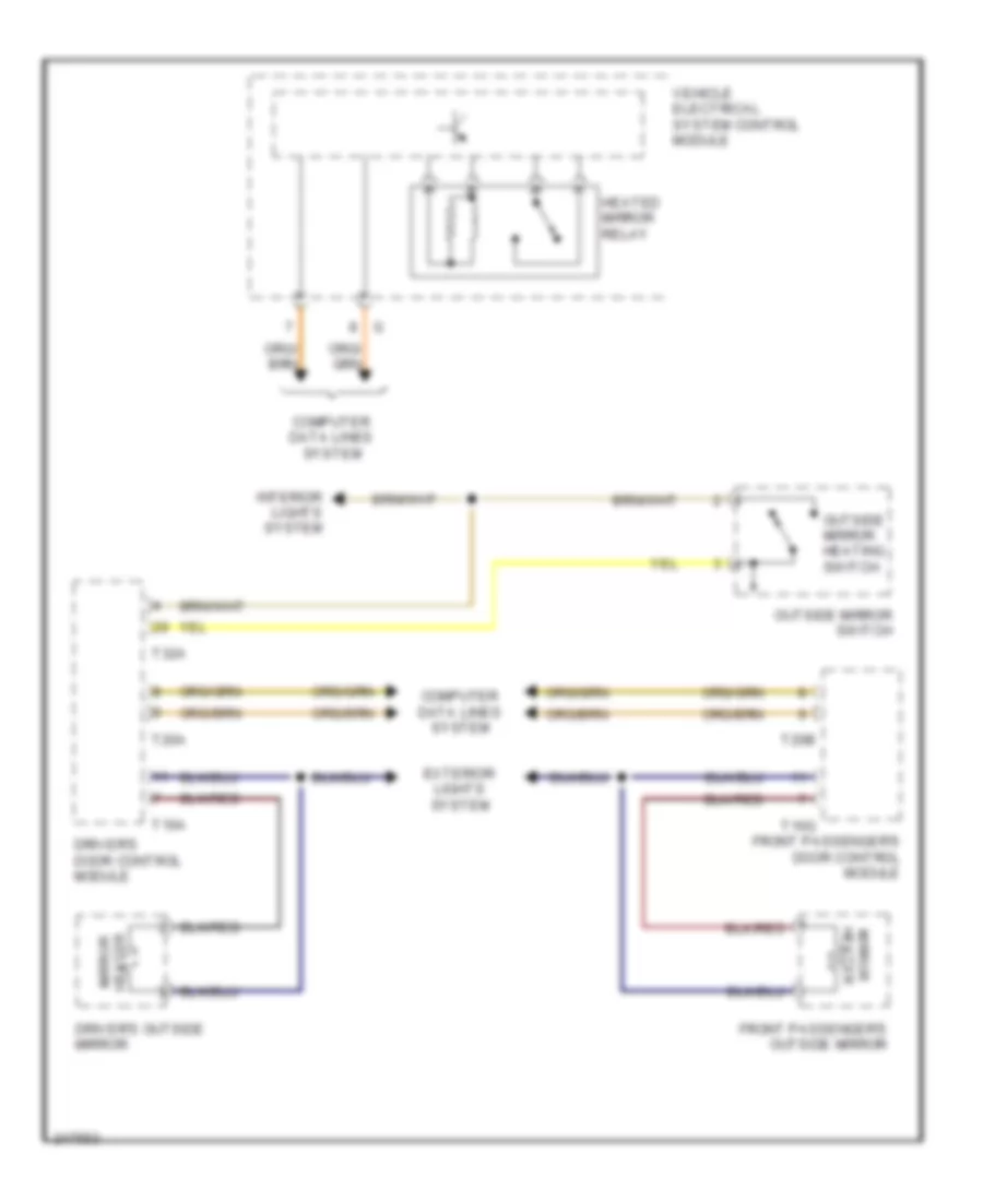
Heated Mirrors Wiring Diagram, Late Production for Volkswagen GTI 2006
 https://portal-diagnostov.com/license.html
Automotive Electricians Portal FZCO
Automotive Electricians Portal FZCO
https://portal-diagnostov.com/license.html
https://portal-diagnostov.com/license.html
Automotive Electricians Portal FZCO
Automotive Electricians Portal FZCOList of elements for Heated Mirrors Wiring Diagram, Late Production for Volkswagen GTI 2006:
- Computer data lines system
- Driver's door control module
- Driver's outside mirror
- Exterior lights system
- Front passenger's door control module
- Front passenger's outside mirror
- Heated mirror relay
- Interior lights system
- Mirror heater
- Outside mirror heating switch
- Outside mirror switch
- T16a
- T16g
- T20a
- T20b
- T32a
- Vehicle electrical system control module
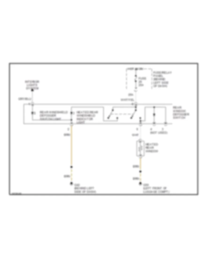
Rear Defogger Wiring Diagram, Early Production for Volkswagen GTI 2006
 https://portal-diagnostov.com/license.html
Automotive Electricians Portal FZCO
Automotive Electricians Portal FZCO
https://portal-diagnostov.com/license.html
https://portal-diagnostov.com/license.html
Automotive Electricians Portal FZCO
Automotive Electricians Portal FZCOList of elements for Rear Defogger Wiring Diagram, Early Production for Volkswagen GTI 2006:
- (not used)
- 26a
- Fuse 25a
- Fuse/relay panel (behind left side of dash)
- G42 (behind left side of dash)
- G50 (left front of luggage compt)
- Heated rear window
- Heated rear windshield indicator light
- Hot in on
- Interior lights system
- Rear window defogger switch
- Rear windshield defogger switch light
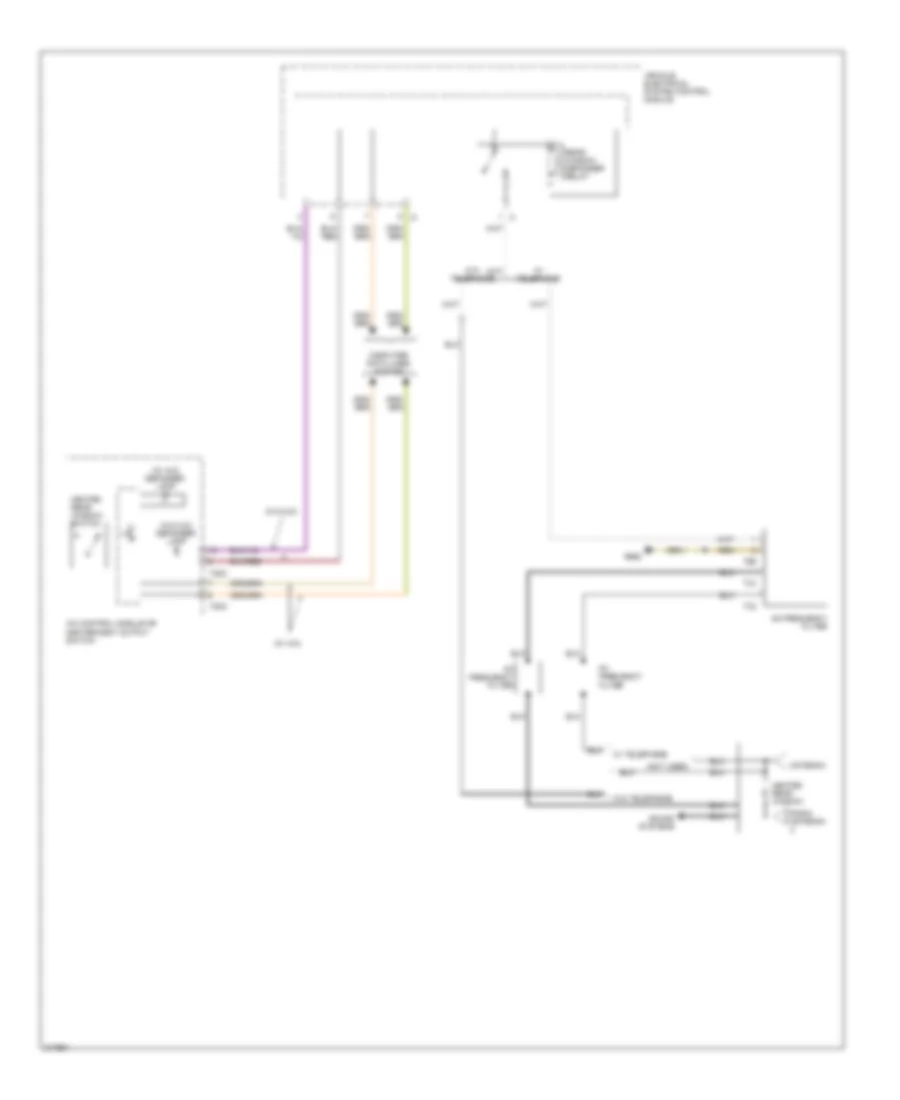
Rear Defogger Wiring Diagram, Late Production for Volkswagen GTI 2006
 https://portal-diagnostov.com/license.html
Automotive Electricians Portal FZCO
Automotive Electricians Portal FZCO
https://portal-diagnostov.com/license.html
https://portal-diagnostov.com/license.html
Automotive Electricians Portal FZCO
Automotive Electricians Portal FZCOList of elements for Rear Defogger Wiring Diagram, Late Production for Volkswagen GTI 2006:
- (not used)
- (w/ a/c)
- (w/ a/c) defogger lamp
- (w/o a/c)
- (w/o a/c) defogger lamp
- A/c control module or heater/heat output switch
- Am frequency filter
- Antenna
- Computer data lines system
- Fm frequency filter
- G662
- Heated rear window
- Heated rear window switch
- Radio antenna
- Rear window defogger relay
- Sound systems
- T1c
- T1d
- T20c
- T2b
- Vehicle electrical system control module
- W/ telephone
- W/o telephone
ELECTRONIC POWER STEERING
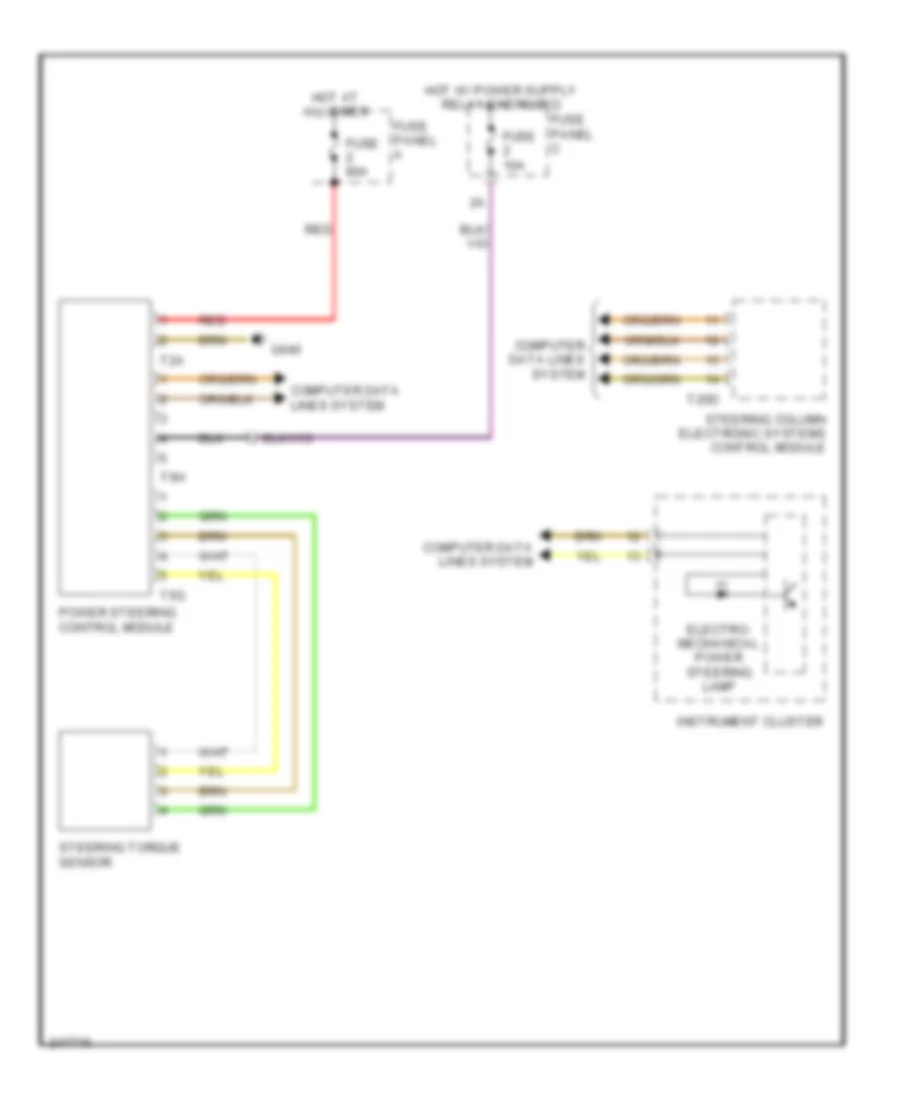
Electronic Power Steering Wiring Diagram for Volkswagen GTI 2006
 https://portal-diagnostov.com/license.html
Automotive Electricians Portal FZCO
Automotive Electricians Portal FZCO
https://portal-diagnostov.com/license.html
https://portal-diagnostov.com/license.html
Automotive Electricians Portal FZCO
Automotive Electricians Portal FZCOList of elements for Electronic Power Steering Wiring Diagram for Volkswagen GTI 2006:
- Computer data lines system
- Electro- mechanical power steering lamp
- Fuse 10a
- Fuse 80a
- Fuse panel a
- Fuse panel c
- G640
- Hot at all times
- Instrument cluster
- Power steering control module
- Red
- Steering column electronic systems control module
- Steering torque sensor
- T20d
- T2a
- T5g
- T5h
ENGINE PERFORMANCE
1.8L TURBO
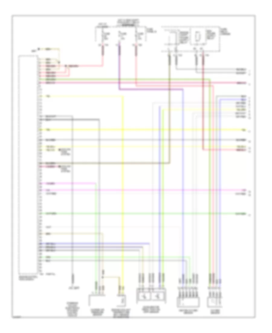
1.8L Turbo, Engine Performance Wiring Diagram (1 of 3) for Volkswagen GTI 2006
 https://portal-diagnostov.com/license.html
Automotive Electricians Portal FZCO
Automotive Electricians Portal FZCO
https://portal-diagnostov.com/license.html
https://portal-diagnostov.com/license.html
Automotive Electricians Portal FZCO
Automotive Electricians Portal FZCOList of elements for 1.8L Turbo, Engine Performance Wiring Diagram (1 of 3) for Volkswagen GTI 2006:
- (a/t)
- (not used)
- (pins 10-20 not used)
- (pins 23, 24 & 26 not used)
- (pins 6-8 not used)
- 29a
- 37a
- A/c system
- A/t
- Accelerator pedal position sensors 1 & 2 (in the pedal assembly)
- Computer data lines system
- Cruise control system
- Evaporative emission canister purge regulator valve
- Fuel pump relay
- Fuse 15a
- Fuse 20a
- Fuse 50a
- Fuse panel
- Fuse/ red bracket battery
- G42 (left side of steer- ing column)
- G608 (left side of firewall)
- Heated oxygen sensor (ho2s)
- Hot at all times
- Hot in run or start
- Ignition switch
- Leak detection pump
- Lock
- M/t
- Mass airflow sensor
- Motronic engine control module (in protective box, in left rear corner of engine compartment)
- Nca
- Oxygen sensor (o2s) (behind catalytic converter)
- Red
- Relay panel
- Run
- Start
- Starting/ charging system
- Transmission system
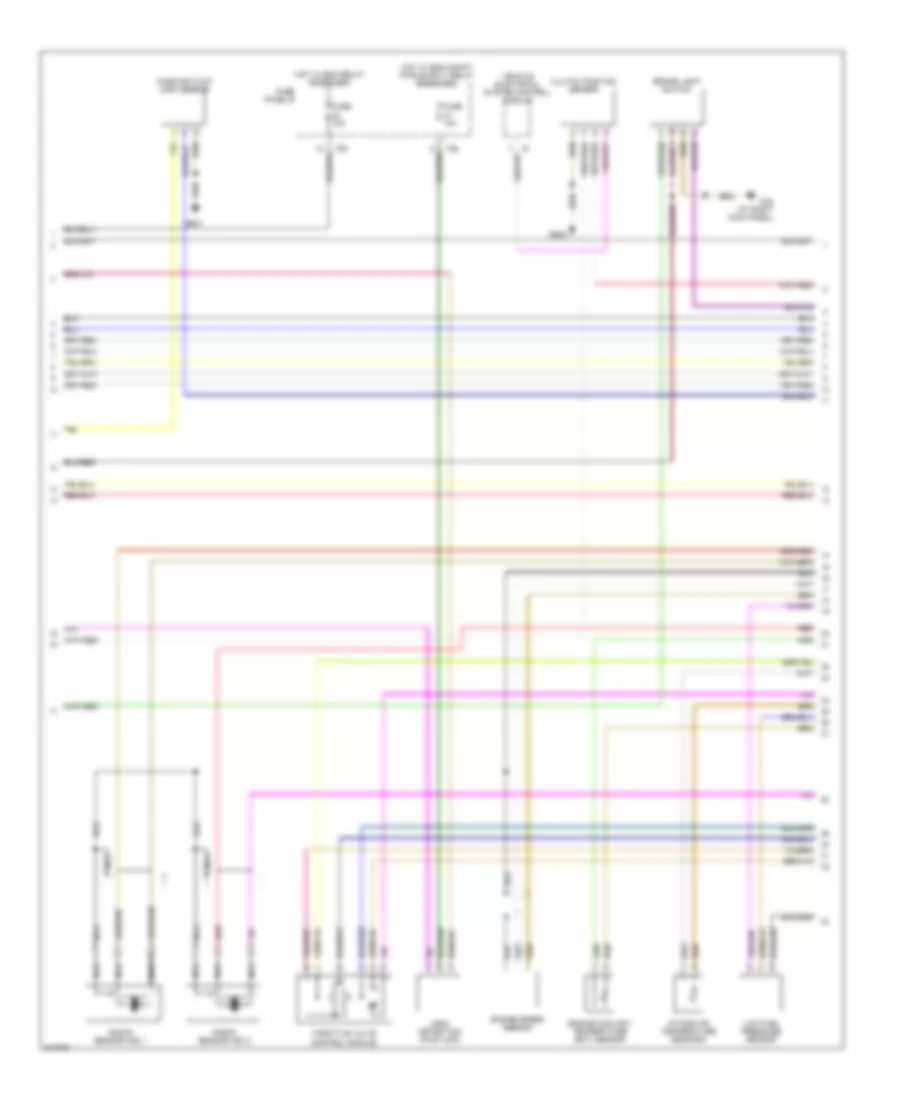
1.8L Turbo, Engine Performance Wiring Diagram (2 of 3) for Volkswagen GTI 2006
 https://portal-diagnostov.com/license.html
Automotive Electricians Portal FZCO
Automotive Electricians Portal FZCO
https://portal-diagnostov.com/license.html
https://portal-diagnostov.com/license.html
Automotive Electricians Portal FZCO
Automotive Electricians Portal FZCOList of elements for 1.8L Turbo, Engine Performance Wiring Diagram (2 of 3) for Volkswagen GTI 2006:
- (left side of steer- ing column)
- 28a
- Brake system vacuum pump (a/t)
- Brake vacuum pump fuse
- Electronic power control fault light
- Engine speed (rpm) sensor
- Fuel pump
- Fuse 10a
- Fuse 15a
- Fuse 20a
- Fuse 50a
- Fuse panel
- Fuse/ bracket battery
- G42
- G42 (left side of steer- ing column)
- G609 (right side of firewall)
- Hot at all times
- Instrument cluster
- Knock sensor 1
- Knock sensor 2
- Malfunction indicator lamp
- Nca
- Power steering pressure switch
- Red
- Secondary air injection pump motor
- Secondary air injection pump relay (in left side of engine compt)
- Secondary air injection solenoid valve
- T32
- T32a
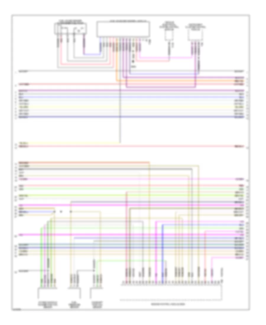
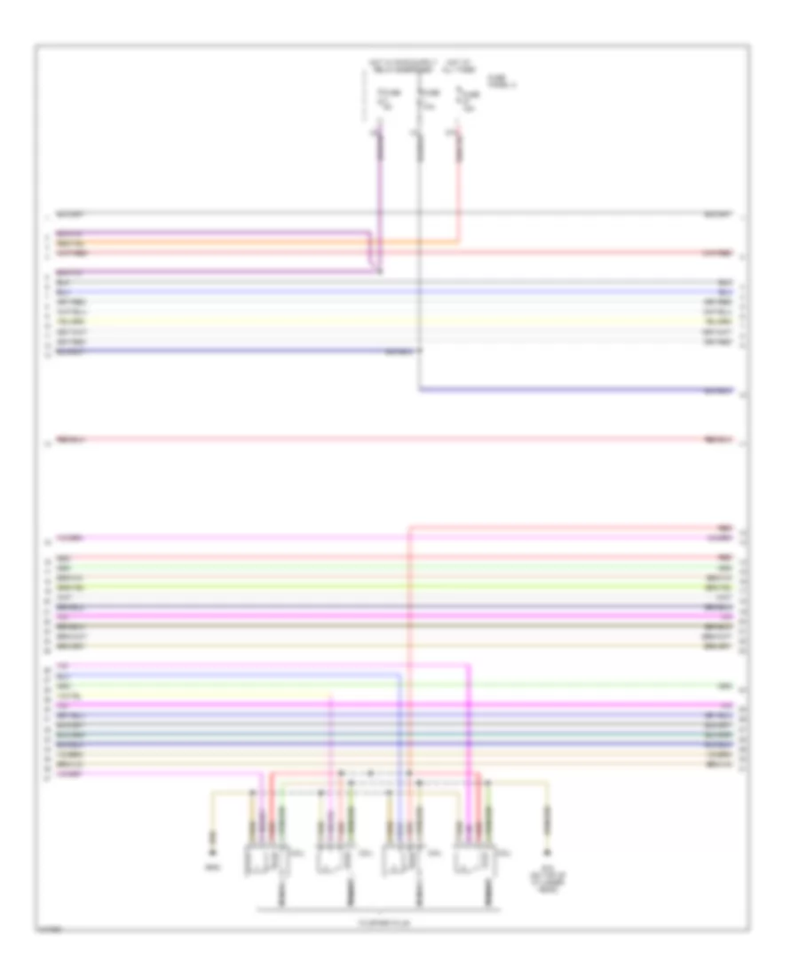
1.8L Turbo, Engine Performance Wiring Diagram (3 of 3) for Volkswagen GTI 2006
 https://portal-diagnostov.com/license.html
Automotive Electricians Portal FZCO
Automotive Electricians Portal FZCO
https://portal-diagnostov.com/license.html
https://portal-diagnostov.com/license.html
Automotive Electricians Portal FZCO
Automotive Electricians Portal FZCOList of elements for 1.8L Turbo, Engine Performance Wiring Diagram (3 of 3) for Volkswagen GTI 2006:
- 13a
- Brake- light switch
- Camshaft adjustment valve 1
- Camshaft position sensor
- Charge air pressure sensor
- Clutch pedal switch
- Cruise control system
- Engine coolant temperature sensor
- Fuel injectors
- Fuse 10a
- Fuse 7.5a
- Fuse panel (behind left side of dash)
- G15 (on cylinder head)
- G608 (center of firewall)
- Hot at all times
- Ignition coils
- Intake air temperature
- Motronic engine control module (in protective box, in left rear corner of engine compt)
- Nca
- Not used
- Throttle valve control module
- To spark plug
- Turbocharger recirculating valve
- Wastegate bypass regu- lator valve
2.0L
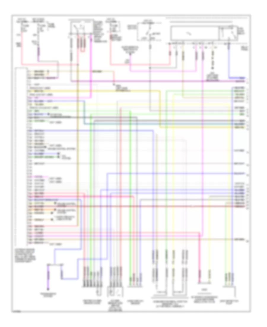
2.0L, Engine Performance Wiring Diagram (1 of 5) for Volkswagen GTI 2006
 https://portal-diagnostov.com/license.html
Automotive Electricians Portal FZCO
Automotive Electricians Portal FZCO
https://portal-diagnostov.com/license.html
https://portal-diagnostov.com/license.html
Automotive Electricians Portal FZCO
Automotive Electricians Portal FZCOList of elements for 2.0L, Engine Performance Wiring Diagram (1 of 5) for Volkswagen GTI 2006:
- Accelerator pedal position (app) sensor
- Charge air pressure sensor
- Cooling fans system
- Engine control module (ecm)
- Engine coolant temperature (ect) sensor (on radiator)
- Fuse 10a
- Fuse 25a
- Fuse panel b
- Fuse/ relay carrier
- G607
- Heated oxygen sensor
- Hot at all times
- Nca
- Oxygen sensor
- Partial
- Steering column electronic systems control module
- T20d
- T23
- T26
- T40
- T94
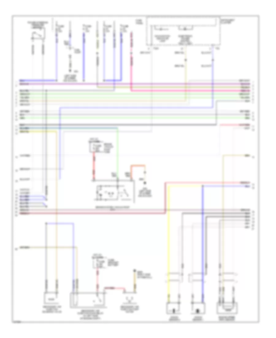
2.0L, Engine Performance Wiring Diagram (2 of 5) for Volkswagen GTI 2006
 https://portal-diagnostov.com/license.html
Automotive Electricians Portal FZCO
Automotive Electricians Portal FZCO
https://portal-diagnostov.com/license.html
https://portal-diagnostov.com/license.html
Automotive Electricians Portal FZCO
Automotive Electricians Portal FZCOList of elements for 2.0L, Engine Performance Wiring Diagram (2 of 5) for Volkswagen GTI 2006:
- Brake light switch
- Clutch position sensor
- Engine coolant temperature (ect) sensor
- Engine speed sensor
- Fuse 10a
- Fuse panel b
- G43 (at right kick panel)
- G605
- G607
- Hot w/ ecm relay energized
- Intake air temperature sensor 2
- Knock sensor (ks) 1
- Knock sensor (ks) 2
- Leak detection pump (ldp)
- Low fuel pressure sensor
- Mass air flow (maf) sensor
- Nca
- Red
- T26
- Throttle valve control module
- Vehicle electrical system control module
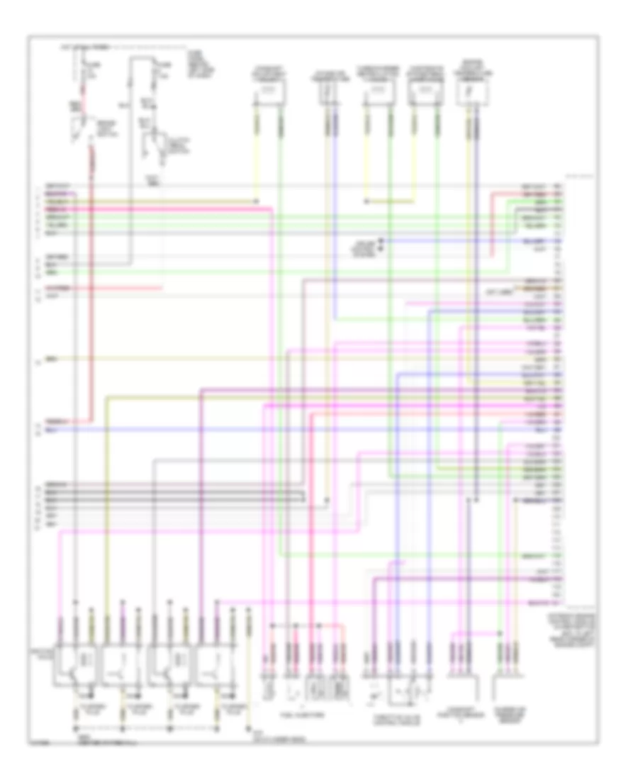
2.0L, Engine Performance Wiring Diagram (3 of 5) for Volkswagen GTI 2006
 https://portal-diagnostov.com/license.html
Automotive Electricians Portal FZCO
Automotive Electricians Portal FZCO
https://portal-diagnostov.com/license.html
https://portal-diagnostov.com/license.html
Automotive Electricians Portal FZCO
Automotive Electricians Portal FZCOList of elements for 2.0L, Engine Performance Wiring Diagram (3 of 5) for Volkswagen GTI 2006:
- Camshaft position sensor
- Engine control module (ecm)
- Fuel gauge sender & transfer fuel pump
- Fuel pressure sensor
- Fuel pump (fp) control module
- G682
- Instrument cluster control module
- Intake manifold runner position sensor
- Partial
- Red
- T10n
- T11b
- T36
- T60
- Vehicle electrical system control module
2.0L, Engine Performance Wiring Diagram (4 of 5) for Volkswagen GTI 2006
 https://portal-diagnostov.com/license.html
Automotive Electricians Portal FZCO
Automotive Electricians Portal FZCO
https://portal-diagnostov.com/license.html
https://portal-diagnostov.com/license.html
Automotive Electricians Portal FZCO
Automotive Electricians Portal FZCOList of elements for 2.0L, Engine Performance Wiring Diagram (4 of 5) for Volkswagen GTI 2006:
- Coil
- Fuse 10a
- Fuse 15a
- Fuse 5a
- Fuse panel c
- G15 (on top of cylinder head)
- G642
- Hot at all times
- Nca
- Red
- To spark plug
2.0L, Engine Performance Wiring Diagram (5 of 5) for Volkswagen GTI 2006
 https://portal-diagnostov.com/license.html
Automotive Electricians Portal FZCO
Automotive Electricians Portal FZCO
https://portal-diagnostov.com/license.html
https://portal-diagnostov.com/license.html
Automotive Electricians Portal FZCO
Automotive Electricians Portal FZCOList of elements for 2.0L, Engine Performance Wiring Diagram (5 of 5) for Volkswagen GTI 2006:
- Camshaft adjustment valve 1
- Computer data lines system
- Engine control module (ecm)
- Evaporative emission canister purge regulator valve
- Fuel injectors
- Fuel pressure regulator valve
- Fuse 10a
- Fuse 15a
- Fuse 20a
- Fuse 5a
- Fuse panel b
- Hot at all times
- Hot w/ ecm relay energized
- Partial
- Red
- Starting/charging system
- T26
- T40
- T60
- T94
- Turbocharger recirculating valve
- Wastegate bypass regulator valve
EXTERIOR LIGHTS
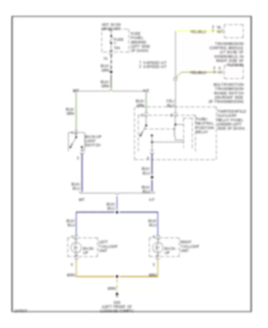
Back-up Lamps Wiring Diagram, Early Production for Volkswagen GTI 2006
 https://portal-diagnostov.com/license.html
Automotive Electricians Portal FZCO
Automotive Electricians Portal FZCO
https://portal-diagnostov.com/license.html
https://portal-diagnostov.com/license.html
Automotive Electricians Portal FZCO
Automotive Electricians Portal FZCOList of elements for Back-up Lamps Wiring Diagram, Early Production for Volkswagen GTI 2006:
- 5-speed a/t 4-speed a/t
- A/t
- Back- up
- Back-up light switch
- Fuse 10a
- Fuse panel (behind left side of dash)
- G50 (left front of luggage compt)
- Hot in on or start
- Left taillight unit
- M/t
- Multifunction transmission range switch (on right side of transmission)
- Park/ neutral position relay
- Right taillight unit
- Thirteenfold auxiliary relay panel (under left side of dash)
- Transmission control module (at base of windshield, in right side of plenum)
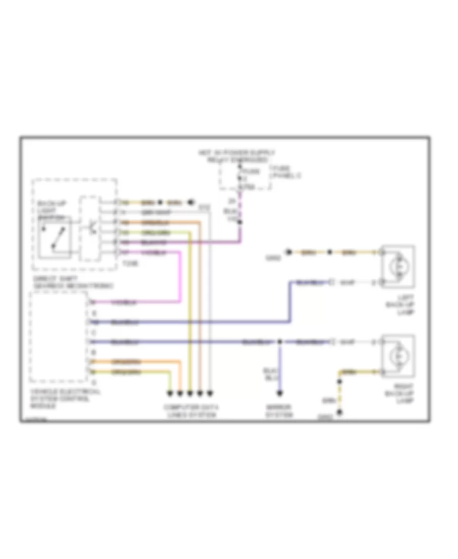
Back-up Lamps Wiring Diagram, Late Production for Volkswagen GTI 2006
 https://portal-diagnostov.com/license.html
Automotive Electricians Portal FZCO
Automotive Electricians Portal FZCO
https://portal-diagnostov.com/license.html
https://portal-diagnostov.com/license.html
Automotive Electricians Portal FZCO
Automotive Electricians Portal FZCOList of elements for Back-up Lamps Wiring Diagram, Late Production for Volkswagen GTI 2006:
- Back-up light switch
- Computer data lines system
- Direct shift gearbox mechatronic
- Fuse 10a
- Fuse panel c
- G12
- G662
- Left back-up lamp
- Mirror system
- Right back-up lamp
- T20e
- Vehicle electrical system control module
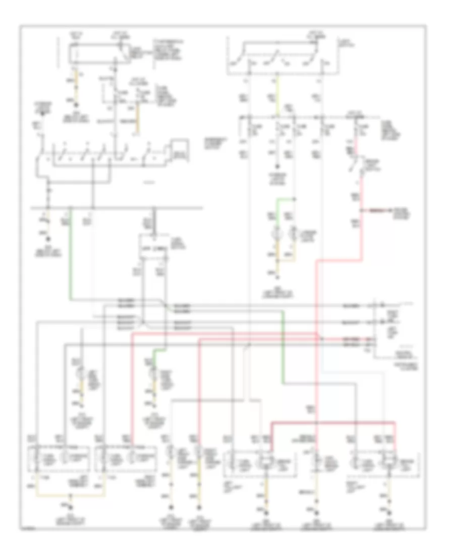
Exterior Lamps Wiring Diagram, Early Production for Volkswagen GTI 2006
 https://portal-diagnostov.com/license.html
Automotive Electricians Portal FZCO
Automotive Electricians Portal FZCO
https://portal-diagnostov.com/license.html
https://portal-diagnostov.com/license.html
Automotive Electricians Portal FZCO
Automotive Electricians Portal FZCOList of elements for Exterior Lamps Wiring Diagram, Early Production for Volkswagen GTI 2006:
- (or 1)
- 13a
- 22a
- 23a
- 39a
- Brake- light switch
- Brake/ tail- light
- Control module
- Cruise control system
- Emergency flasher switch
- Fuse 10a
- Fuse 15a
- Fuse 5a
- Fuse panel (behind left side of dash)
- G12 (left front of engine compt)
- G42 (below left side of dash)
- G50 (left front of luggage compt)
- High mount brake- light
- Hot at all times
- Hot in run
- Instrument cluster
- Interior lights system
- Left
- Left front side marker light
- Left headlight assembly
- Left side turn signal light
- Left taillight unit
- Left turn ind
- License plate lights
- Light switch
- Load reduction relay
- Off
- Parking light
- Right
- Right front side marker light
- Right headlight assembly
- Right side turn signal light
- Right taillight unit
- Right turn ind
- Solid state
- T10b
- T10c
- T32
- Thirteenfold auxiliary relay panel (under left side of dash)
- Turn signal light
- Turn signal switch
Exterior Lamps Wiring Diagram, Late Production (1 of 2) for Volkswagen GTI 2006
 https://portal-diagnostov.com/license.html
Automotive Electricians Portal FZCO
Automotive Electricians Portal FZCO
https://portal-diagnostov.com/license.html
https://portal-diagnostov.com/license.html
Automotive Electricians Portal FZCO
Automotive Electricians Portal FZCOList of elements for Exterior Lamps Wiring Diagram, Late Production (1 of 2) for Volkswagen GTI 2006:
- 13a
- Anti-lock brakes system
- Brake light switch
- Computer data lines system
- Data bus on board diagnostic interface
- Driver's door control module
- Driver's outside mirror
- Engine control module
- Front passenger's door control module
- Front passenger's outside mirror
- Fuse 10a
- Fuse 2a 10a
- Fuse panel c
- G43
- G655
- G656
- Hot at all times
- Instrument cluster
- Instrument cluster control module
- Left exterior mirror turn signal lamp
- Left front side marker lamp
- Left parking lamp
- Left turn signal indicator
- Left turn signal lamp
- Light switch
- Red
- Right exterior mirror turn signal lamp
- Right front side marker lamp
- Right parking lamp
- Right turn signal indicator
- Right turn signal lamp
- Steering column electronic systems control module
- T10y
- T16a
- T16g
- T20
- T20a
- T20b
- T20d
- T36
- Turn signal switch
- Turn signal switch/ headlamp dimmer/flasher switch
- Vehicle electrical system control module
Exterior Lamps Wiring Diagram, Late Production (2 of 2) for Volkswagen GTI 2006
 https://portal-diagnostov.com/license.html
Automotive Electricians Portal FZCO
Automotive Electricians Portal FZCO
https://portal-diagnostov.com/license.html
https://portal-diagnostov.com/license.html
Automotive Electricians Portal FZCO
Automotive Electricians Portal FZCOList of elements for Exterior Lamps Wiring Diagram, Late Production (2 of 2) for Volkswagen GTI 2006:
- Emergency flasher switch
- G47
- G662
- G682
- High- mount brake light
- Left brake lamp
- Left taillamp assembly
- Left turn signal lamp
- License plate lights
- Right brake lamp
- Right taillamp assembly
- Right turn signal lamp
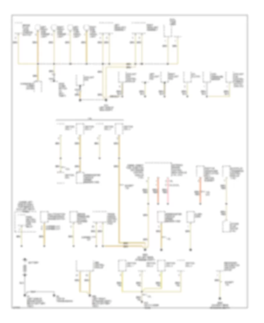
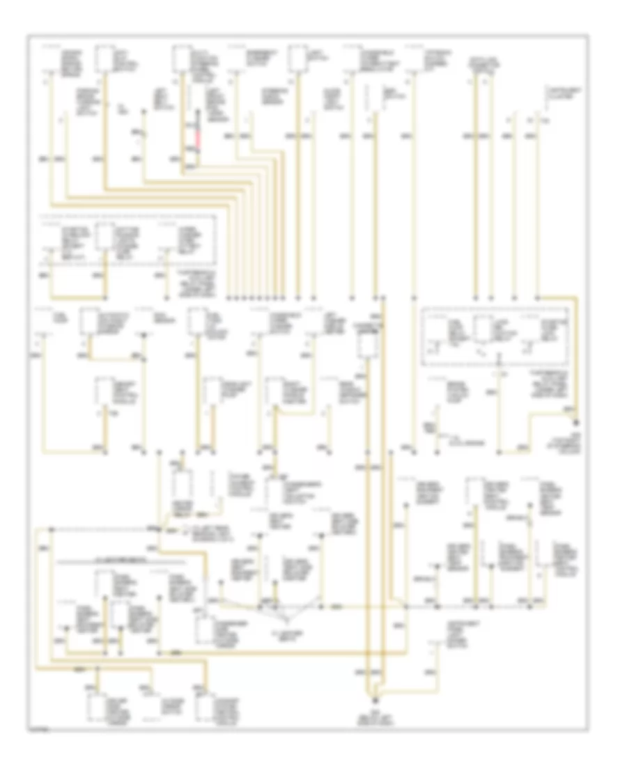
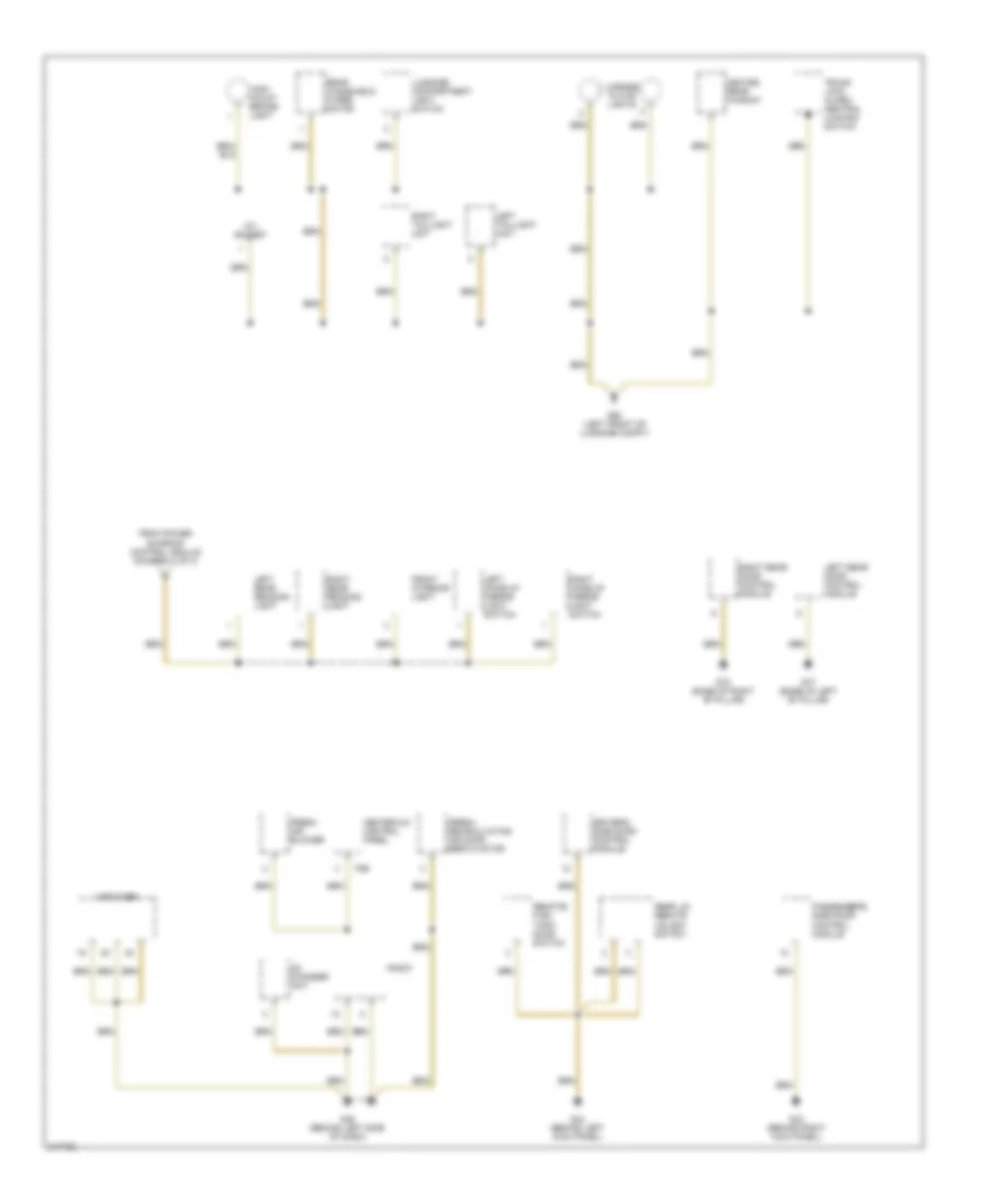
GROUND DISTRIBUTION
Ground Distribution Wiring Diagram, Early Production (1 of 3) for Volkswagen GTI 2006
 https://portal-diagnostov.com/license.html
Automotive Electricians Portal FZCO
Automotive Electricians Portal FZCO
https://portal-diagnostov.com/license.html
https://portal-diagnostov.com/license.html
Automotive Electricians Portal FZCO
Automotive Electricians Portal FZCOList of elements for Ground Distribution Wiring Diagram, Early Production (1 of 3) for Volkswagen GTI 2006:
- (4-speed a/t) (5-speed a/t)
- (under left side of dash) thirteenfold auxiliary relay panel
- 1.8l
- 1.9l
- 1.9l 1.8l & 2.0l
- 1.9l, 2.0l
- 2.0l
- 5-speed a/t
- A/c clutch
- Abs control module
- Alarm horn
- Battery
- Brake fluid level warning switch
- Brake pressure switch (5-speed a/t)
- Coolant fan
- Coolant fan control module
- Coolant fan control thermal switch (man a/c)
- Diesel direct fuel injection (dfi) engine control module (1.9l)
- Dual tone horn
- Except 1.9l
- G1 (left side of engine compt, below battery tray)
- G12 (left side of eng compt)
- G15 (on cylinder head)
- G2 (top of transmission)
- G608 (on left rear of engine compt)
- G609 (on right rear or engine compt)
- G65 (left front of engine compt) below battery tray)
- Glowplug triggering control module (1.9l)
- High pressure sensor
- Hood alarm switch (w/ anti- theft)
- Ignition coil
- Ignition coil 1
- Ignition coil 2
- Ignition coil 3
- Ignition coil 4
- Intake flap motor (1.9l)
- Left coolant fan
- Left front side marker light
- Left headlight assembly
- Left side turn signal light
- Motronic engine control (ecm) module (1.8l, 2.0l)
- Multifunction transmission range switch
- Nca
- Park/ neutral position (pnp) relay
- Positive crankcase ventilation (pcv) heating element
- Right coolant fan
- Right front side marker light
- Right headlight assembly
- Right side turn signal light
- Secondary air injection (air) pump motor
- Speedometer vehicle speed sensor (vss)
- Trans- mission control module (tcm)
- Windshield wiper motor
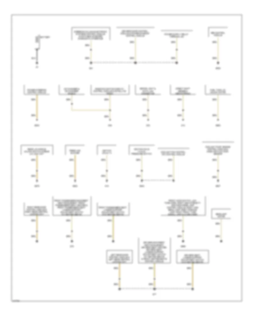
Ground Distribution Wiring Diagram, Early Production (2 of 3) for Volkswagen GTI 2006
 https://portal-diagnostov.com/license.html
Automotive Electricians Portal FZCO
Automotive Electricians Portal FZCO
https://portal-diagnostov.com/license.html
https://portal-diagnostov.com/license.html
Automotive Electricians Portal FZCO
Automotive Electricians Portal FZCOList of elements for Ground Distribution Wiring Diagram, Early Production (2 of 3) for Volkswagen GTI 2006:
- 1.8l & 2.0l engine
- Air bag spiral spring/ return spring
- Anti- slip control switch
- Automatic day/night interior mirror
- Brake system vacuum pump
- Cigarette lighter
- Comfort system central control module
- Data link connector for dlc
- Daytime running lights change- over relay
- Driver side heated outside mirror
- Driver's backrest heating element
- Driver's heated seat control module
- Driver's heated seat temp sensor
- Driver's seat backrest heater
- Driver's seat heater
- Driver's seat side bolster heater
- Driver's seat side bolster heater 2
- Emergency flasher switch
- Esp switch
- Fuel pump
- Fuel pump relay (except 1.9l)
- Fuel tank lid unlock motor
- G42 (below left side of dash)
- G49 (top right of steering column)
- Glove compt light switch
- Headlight washer pump
- Heated mirror relay
- Instrument cluster
- Instrument panel light dimmer switch
- Left front brake pad wear sensor
- Left seat belt switch
- Left washer nozzle heater
- Light switch
- Load re- duction relay
- Memory seat control module
- Multi- function steering wheel control module
- Outside mirror switch
- Parking brake warning light switch
- Pass- enger's backrest heating element
- Pass- enger's heated seat control module
- Pass- enger's heated seat temp sensor
- Pass- enger's seat backrest heater
- Pass- enger's seat heater
- Pass- enger's seat side bolster heater
- Pass- enger's seat side bolster heater 2
- Passenger side heated outside mirror
- Passenger's seat adjusting switch
- Power sunroof control module
- Rain sensor
- Rear window defogger switch
- Red
- Right washer nozzle heater
- Starting inter- lock relay
- Starting interlock relay (except 2.0l bbw m/t)
- Steering angle sensor
- T2b
- T32
- T8f
- Thirteenfold auxiliary relay panel (under left side of dash)
- Tiptronic switch (5-speed a/t)
- To left rear reading light (diagram 3 of 3)
- W/ asc
- W/ leather seats
- Windshield wiper intermittent regulator
- Windshield wiper/ washer switch
- Wiper/ washer inter- mittent relay
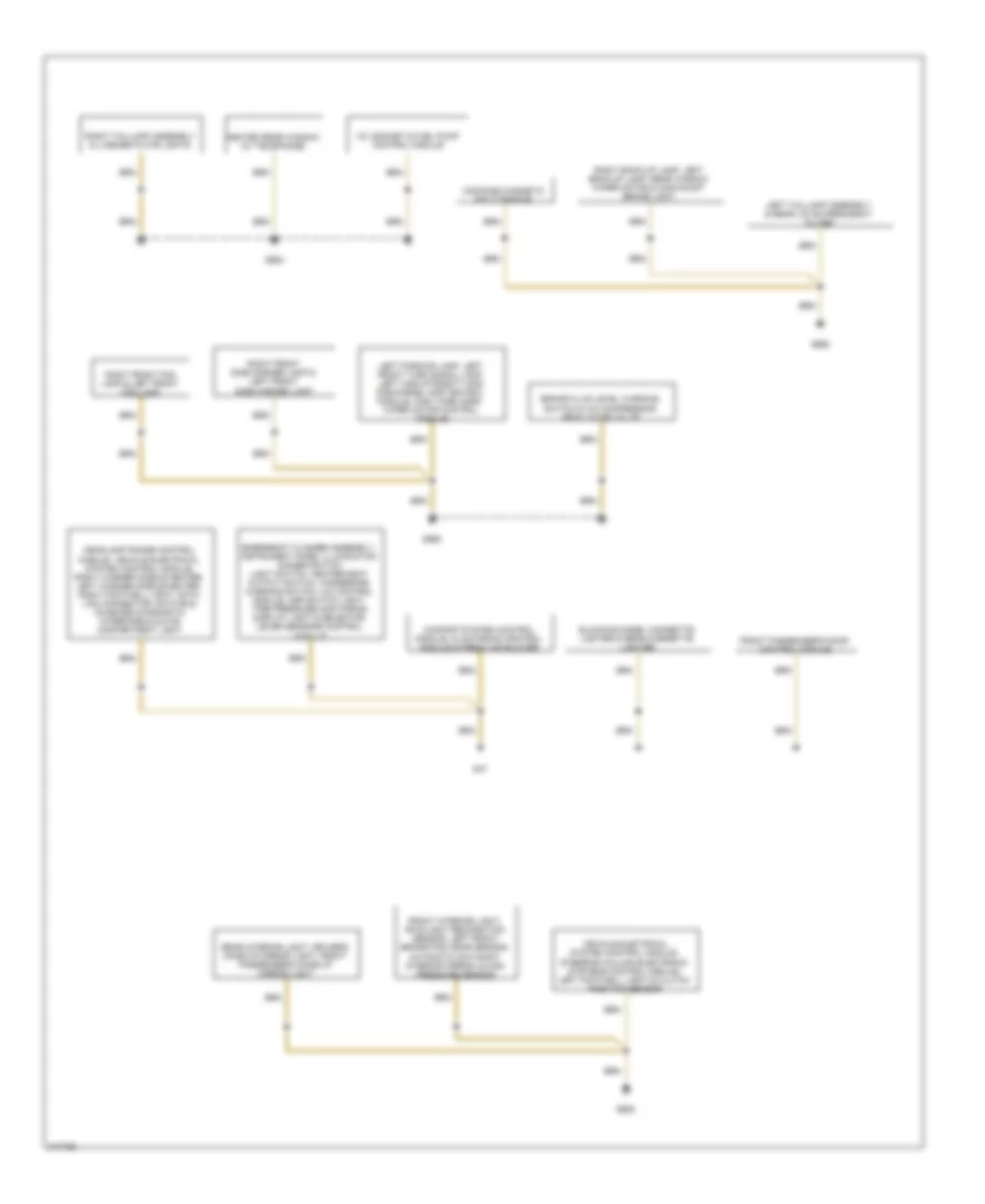
Ground Distribution Wiring Diagram, Early Production (3 of 3) for Volkswagen GTI 2006
 https://portal-diagnostov.com/license.html
Automotive Electricians Portal FZCO
Automotive Electricians Portal FZCO
https://portal-diagnostov.com/license.html
https://portal-diagnostov.com/license.html
Automotive Electricians Portal FZCO
Automotive Electricians Portal FZCOList of elements for Ground Distribution Wiring Diagram, Early Production (3 of 3) for Volkswagen GTI 2006:
- 12v socket
- Amplifier
- Cd changer unit
- Driver's side door control module
- Fresh air blower
- Fresh- recirculating air door servo motor
- From power sunroof control module (diagram 2 of 3)
- Front interior light
- G43 (behind right kick panel)
- G44 (behind left kick panel)
- G45 (behind left side of dash)
- G50 (left front of luggage compt)
- G77 (base of left "b" pillar)
- G78 (base of right "b" pillar)
- Heated rear window
- Heater-a/c control panel
- High- mount brake- light
- Left make-up mirror light switch
- Left rear door control module
- Left rear reading light
- Left taillight unit
- License plate lights
- Luggage compartment light switch
- Passenger's side door control module
- Radio
- Rear lid remote unlock switch
- Rear windshield wiper motor
- Remote/ fuel tank door switch
- Right make-up mirror light switch
- Right rear door control module
- Right rear reading light
- Right taillight unit
- T8b
- Trunk lock alarm/ central locking switch
Ground Distribution Wiring Diagram, Late Production (1 of 2) for Volkswagen GTI 2006
 https://portal-diagnostov.com/license.html
Automotive Electricians Portal FZCO
Automotive Electricians Portal FZCO
https://portal-diagnostov.com/license.html
https://portal-diagnostov.com/license.html
Automotive Electricians Portal FZCO
Automotive Electricians Portal FZCOList of elements for Ground Distribution Wiring Diagram, Late Production (1 of 2) for Volkswagen GTI 2006:
- Abs control module
- Battery
- Brake light & data link connector
- Cd changer & cd changer shield
- Coolant fan control (fc) control module
- Coolant pump, engine control module & mass air flow (maf) sensor
- Direct shift gearbox mechatronic
- Driver's backrest heating element, driver's seat heater, driver's seat lumbar support adjustment switch (w/ heated seats) & front heated seats control module
- Driver's door control module & power sunroof control module
- Driver's seat lumbar support adjustment switch (w/o heated seats)
- Fresh air blower
- Front hood switch, low tone horn, right high-intensity gas discharge lamp control module, right high beam lamp, right parking lamp, right front turn signal lamp & alarm horn
- Front passenger's backrest heating element, front passenger's seat heater & front passenger's seat lumbar support adjustment switch (w/ heated seats)
- Front passenger's seat lumbar support adjustment switch (w/o heated seats)
- Fuel tank lid unlock motor
- G12
- G15
- G43
- G44
- G45
- G602
- G607
- G638
- G640
- G642
- G656
- G663
- G679
- G77
- G78
- Headlamp motor
- Ignition coils 1-4
- Ignition coils 1-4 & oil pressure switch
- Left rear door control module & left rear central locking unit
- Power steering control module
- Radio/navigation display control module & satellite radio
- Rear lid handle unlock switch & rear lid lock unit
- Right rear door control module & right rear central locking unit
- Steering column electronic systems control module, & data bus on board diagnostic interface
Ground Distribution Wiring Diagram, Late Production (2 of 2) for Volkswagen GTI 2006
 https://portal-diagnostov.com/license.html
Automotive Electricians Portal FZCO
Automotive Electricians Portal FZCO
https://portal-diagnostov.com/license.html
https://portal-diagnostov.com/license.html
Automotive Electricians Portal FZCO
Automotive Electricians Portal FZCOList of elements for Ground Distribution Wiring Diagram, Late Production (2 of 2) for Volkswagen GTI 2006:
- 12v socket & fuel pump control module
- Blocking diode, cigarette lighter & rear cigarette lighter
- Brake fluid level warning switch & a/c compressor regulator valve
- Comfort system control module, climatronic control module & fresh air blower
- Compass magnetic field sensor
- Emergency flasher assembly, instrument panel illumination dimmer switch light switch, heater/heat output switch, handbrake warning switch, a/c control module, asr switch light, tire pressure monitoring display light & selector lever sensors control module
- Front interior light, rain/light recognition sensor, left front brake pad wear sensor, automatic day/night interior mirror, & high pressure sensor
- Front passenger's door control module
- G47
- G605
- G655
- G662
- G682
- Headlamp range control module, vehicle electrical system control module, right washer nozzle heater, left washer nozzle heater, right footwell light, data link connector, data bus on board diagnostic interface & glove compartment light
- Heated rear window (w/ telephone)
- Left parking lamp, left front turn signal lamp, left high-intensity gas discharge lamp control module, high tone horn, wiper motor control module
- Left taillamp assembly & rear lid am frequency filter
- Rear interior light, driver's make-up mirror light, front passenger's make-up mirror light
- Right back-up lamp, left back-up lamp, rear window wiper motor & high-mount brake light
- Right front fog lamp & left front fog lamp
- Right front side marker lamp & left front side marker lamp
- Right taillamp assembly & license plate lights
- Vehicle electrical system control module, steering column electronic systems control module, left footwell light & clutch position sensor
HEADLIGHTS
Headlights Wiring Diagram, Early Production for Volkswagen GTI 2006
 https://portal-diagnostov.com/license.html
Automotive Electricians Portal FZCO
Automotive Electricians Portal FZCO
https://portal-diagnostov.com/license.html
https://portal-diagnostov.com/license.html
Automotive Electricians Portal FZCO
Automotive Electricians Portal FZCOList of elements for Headlights Wiring Diagram, Early Production for Volkswagen GTI 2006:
- (behind left side of dash) thirteen position auxiliary relay panel
- 18a
- 19a
- 20a
- 21a
- 36a
- Bat
- Control module
- Daytime running lights change- over relay
- Dimmer switch
- Flash to pass
- Fog
- Fog- light relay
- Fog- light switch
- Fuse 10a
- Fuse 15a
- Fuse 5a
- Fuse 7.5a
- Fuse panel (behind left side of dash)
- G12 (left front of engine compt)
- G42 (below left side of dash)
- Headlight dimmer/ flasher switch
- Headlight switch
- High
- High beam ind
- Hot at all times
- Hot in on or start
- Ignition switch
- Instrument cluster
- Interior lights system
- Left high headlight assembly
- Light switch
- Lock
- Low
- Off
- Parking brake ind
- Red
- Right headlight assembly
- Start
- T32
- T32a
- Thirteen- fold auxiliary relay panel (under left side of dash)
Headlights Wiring Diagram, Late Production (1 of 2) for Volkswagen GTI 2006
 https://portal-diagnostov.com/license.html
Automotive Electricians Portal FZCO
Automotive Electricians Portal FZCO
https://portal-diagnostov.com/license.html
https://portal-diagnostov.com/license.html
Automotive Electricians Portal FZCO
Automotive Electricians Portal FZCOList of elements for Headlights Wiring Diagram, Late Production (1 of 2) for Volkswagen GTI 2006:
- 13a
- Computer data lines system
- Fog lamp switch
- Fuse 10a
- Fuse panel c
- G655
- Headlamp dimmer/ flasher switch
- High beam indicator
- Hot at all times
- Instrument cluster
- Instrument cluster control module
- Interior lights system
- Left front fog lamp
- Left high beam headlamp
- Left high-intensity gas discharge lamp
- Left high-intensity gas discharge lamp control module
- Left low beam reflector motor
- Light switch
- Power distribution system
- Red
- Right front fog lamp
- Steering column electronic systems control module
- T10y
- T20d
- T36
- Turn signal switch/ headlamp dimmer/ flasher switch
- Vehicle electrical system control module
Headlights Wiring Diagram, Late Production (2 of 2) for Volkswagen GTI 2006
 https://portal-diagnostov.com/license.html
Automotive Electricians Portal FZCO
Automotive Electricians Portal FZCO
https://portal-diagnostov.com/license.html
https://portal-diagnostov.com/license.html
Automotive Electricians Portal FZCO
Automotive Electricians Portal FZCOList of elements for Headlights Wiring Diagram, Late Production (2 of 2) for Volkswagen GTI 2006:
- G47
- G656
- Headlamp range control module
- Left front level control system sensor
- Left headlamp beam adjustment motor
- Left rear level control system sensor
- Red
- Right headlamp beam adjustment motor
- Right high beam headlamp
- Right high-intensity gas discharge lamp
- Right high-intensity gas discharge lamp control module
- Right low beam reflector motor
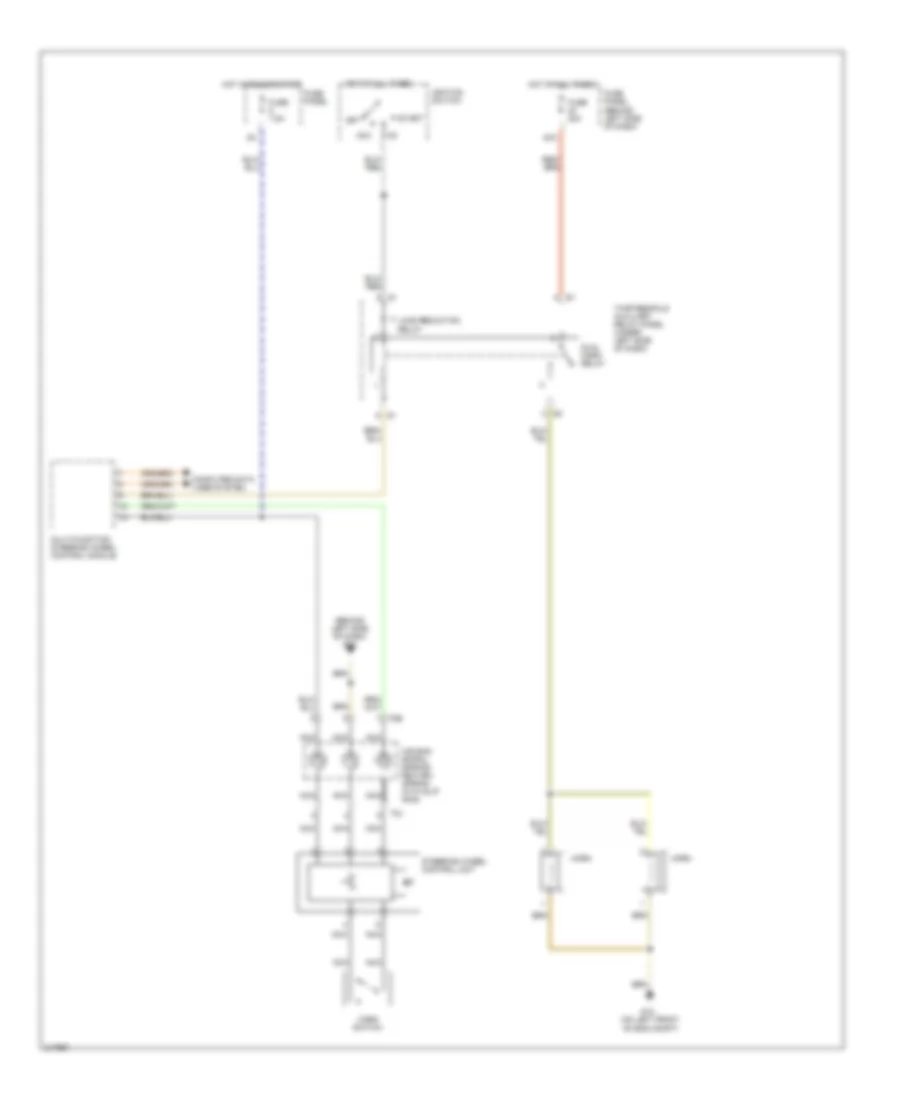
HORN
Horn Wiring Diagram, Early Production with Steering Wheel Controls for Volkswagen GTI 2006
 https://portal-diagnostov.com/license.html
Automotive Electricians Portal FZCO
Automotive Electricians Portal FZCO
https://portal-diagnostov.com/license.html
https://portal-diagnostov.com/license.html
Automotive Electricians Portal FZCO
Automotive Electricians Portal FZCOList of elements for Horn Wiring Diagram, Early Production with Steering Wheel Controls for Volkswagen GTI 2006:
- (behind left side of dash) g42
- 40a
- Acc
- Air bag spiral spring/ return spring with slip ring
- Computer data lines system
- Dual horn relay
- Fuse 20a
- Fuse 7.5a
- Fuse panel
- Fuse panel (behind left side of dash)
- G12 (on left front of eng compt)
- Horn
- Horn switch
- Hot at all times
- Hot in run or start
- Ignition switch
- Load reduction relay
- Multi-function steering wheel control module
- Nca
- Off
- Start
- Steering wheel control unit
- T5b
- T5j
- Thirteenfold auxiliary relay panel (under left side of dash)
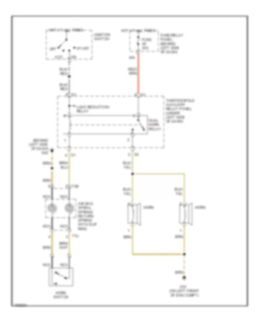
Horn Wiring Diagram, Early Production without Steering Wheel Controls for Volkswagen GTI 2006
 https://portal-diagnostov.com/license.html
Automotive Electricians Portal FZCO
Automotive Electricians Portal FZCO
https://portal-diagnostov.com/license.html
https://portal-diagnostov.com/license.html
Automotive Electricians Portal FZCO
Automotive Electricians Portal FZCOList of elements for Horn Wiring Diagram, Early Production without Steering Wheel Controls for Volkswagen GTI 2006:
- (behind left side of dash) g42
- 40a
- Acc
- Air bag spiral spring/ return spring with slip ring
- Dual horn relay
- Fuse 20a
- Fuse/relay panel (behind left side of dash)
- G12 (on left front of eng compt)
- Horn
- Horn switch
- Hot at all times
- Ignition switch
- Load reduction relay
- Nca
- Off
- Start
- T5b
- T5j
- Thirteenfold auxiliary relay panel (under left side of dash)
Horn Wiring Diagram, Late Production for Volkswagen GTI 2006
 https://portal-diagnostov.com/license.html
Automotive Electricians Portal FZCO
Automotive Electricians Portal FZCO
https://portal-diagnostov.com/license.html
https://portal-diagnostov.com/license.html
Automotive Electricians Portal FZCO
Automotive Electricians Portal FZCOList of elements for Horn Wiring Diagram, Late Production for Volkswagen GTI 2006:
- Airbag spiral spring/ return spring (w/ slip ring)
- Computer data lines system
- Fuse 5a
- Fuse panel b
- G44
- G655
- G656
- High tone horn
- Horn relay
- Horn switch
- Hot at all times
- Low tone horn
- Multi-function steering wheel control module
- Steering column electronic systems control module
- T10x
- T12k
- T20d
- T40
- T5k
- Vehicle electrical system control module
- W/ steering wheel controls
- W/o steering wheel controls
INSTRUMENT CLUSTER
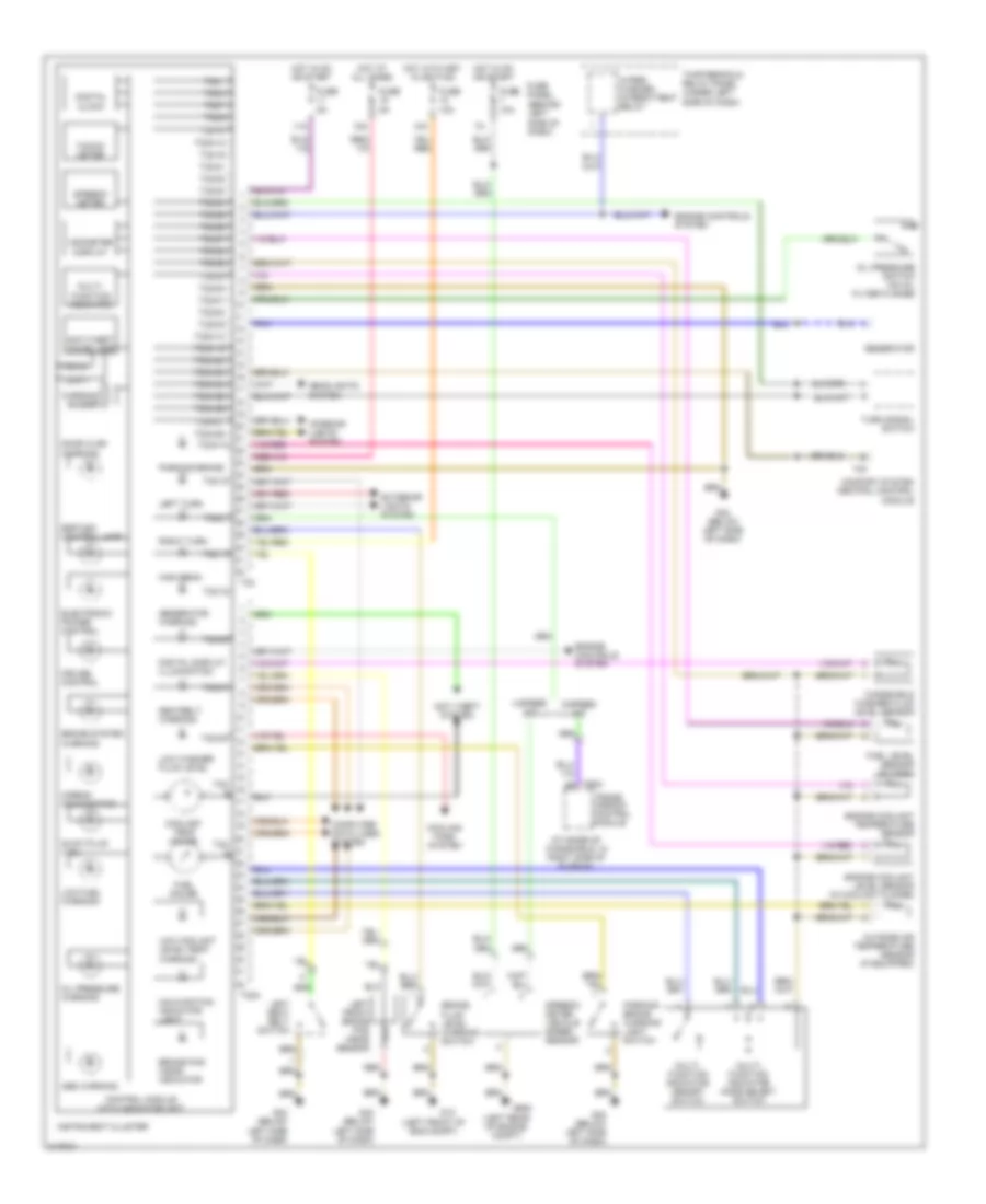
Instrument Cluster Wiring Diagram, Early Production for Volkswagen GTI 2006
 https://portal-diagnostov.com/license.html
Automotive Electricians Portal FZCO
Automotive Electricians Portal FZCO
https://portal-diagnostov.com/license.html
https://portal-diagnostov.com/license.html
Automotive Electricians Portal FZCO
Automotive Electricians Portal FZCOList of elements for Instrument Cluster Wiring Diagram, Early Production for Volkswagen GTI 2006:
- (at base of windshield, in right side of plenum)
- (behind left side of dash)
- (left front of eng compt)
- (left rear of engine compt)
- 10a
- 11a
- 15a
- 4-speed a/t
- 5-speed a/t
- Abs warning
- Airbag malfunction
- Anti theft system
- Anti-theft immobilizer
- Brake fluid level warning switch
- Brake pad wear indicator
- Brake system warning
- Comfort system central control module
- Computer data lines system
- Control module with indicator unit
- Coolant temp gauge
- Cooling fans system
- Cruise control
- Digital clock
- Digital display illumination
- Door ajar warning
- Electronic power control
- Engine controls system
- Engine coolant level sensor (in coolant flange)
- Engine coolant temperature sensor
- Esp/asc control lamp
- Exterior lights system
- Fuel gauge
- Fuel level sensor (in tank)
- Fuse 10a
- Fuse 5a
- Fuse 10a
- Fuse 5a
- Fuse panel
- G12
- G42 (below left side of dash)
- G608
- Generator
- Generator warning
- Glow plug (1.9l)
- Headlights system
- High beam
- Hot at all times
- Hot in on or start
- Hot with key in ignition
- Instrument cluster
- Interior lights system
- Left front brake pad wear sensor
- Left seat belt switch
- Left turn
- Low coolant level/temp warning
- Low fuel warning
- Low washer fluid level
- Malfunction indicator light
- Multi- function indicator
- Multi- function indicator memory switch
- Multi- function indicator mode select switch
- Odometer display
- Oil pressure switch (on oil filter flange)
- Oil pressure warning
- Outside air temperature sensor (if equipped)
- Parking brake
- Parking brake warning light switch
- Red
- Right turn
- Seatbelt warning
- Speedo- meter
- Speedo- meter vehicle speed sensor
- T23
- T32
- T32/
- T32/1
- T32/10
- T32/12
- T32/16
- T32/17
- T32/18
- T32/2
- T32/20
- T32/21
- T32/22
- T32/23
- T32/24
- T32/25
- T32/26
- T32/27
- T32/28
- T32/29
- T32/3
- T32/30
- T32/31
- T32/7
- T32/9
- T32a
- T32a/12
- T32a/13
- T32a/17
- T32a/19
- T32a/2
- T32a/20
- T32a/23
- T32a/24
- T32a/25
- T32a/26
- T32a/27
- T32a/28
- T32a/5
- T32a/6
- T32a/7
- T32a/8
- T32a/9
- T68a
- Tacho- meter
- Thirteenfold relay panel (under left side of dash)
- Trans- mission control module
- Turn signal switch
- Warning buzzer
- Windshield washer fluid level sensor
- Wiper/ washer intermittent relay
Instrument Cluster Wiring Diagram, Late Production for Volkswagen GTI 2006
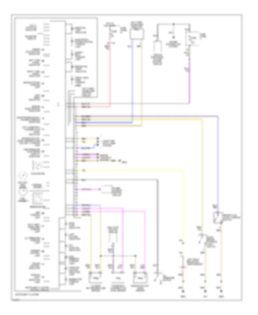 https://portal-diagnostov.com/license.html
Automotive Electricians Portal FZCO
Automotive Electricians Portal FZCO
https://portal-diagnostov.com/license.html
https://portal-diagnostov.com/license.html
Automotive Electricians Portal FZCO
Automotive Electricians Portal FZCOList of elements for Instrument Cluster Wiring Diagram, Late Production for Volkswagen GTI 2006:
- Abs warning lamp
- Airbag malfunction indicator
- Anti-theft immbolizer warning lamp
- Anti-theft immobilizer control module
- Anti-theft immobilizer induction coil
- Asr/esp control lamp
- Brake fluid level warning switch
- Brake pad wear indicator
- Brake system warning lamp
- Computer data lines system
- Coolant temp gauge
- Cruise control indicator
- Door ajar indicator
- Electromechanical power steering indicator
- Electronic power control warning lamp
- Engine controls system
- Engine coolant level sensor
- Engine coolant level/temperature (ecl/ect) warning lamp
- Engine electronics indicator
- Front hood open warning lamp
- Fuel gauge
- Fuel pump control module
- Fuel reserve warning lamp
- Fuse 10a
- Fuse 5a
- Fuse panel b
- Fuse panel c
- G47
- G605
- G655
- Generator warning lamp
- Hand- brake warning light switch
- High beam indicator
- Hot at all times
- Instrument cluster
- Instrument cluster control module
- Lamp failure indicator
- Left front brake pad wear sensor
- Left turn signal indicator
- Low windshield washer fluid level indicator
- Mal- function indicator
- Multi- function indicator
- Odometer display
- Oil pressure switch
- Oil pressure warning lamp
- Outside air temperature sensor
- Parking light indicator lamp
- Power distribution system
- Power sunroof control module
- Rear fog lamp indicator
- Red
- Right turn signal indicator
- Safety belt warning lamp
- Speedometer
- T40
- Tachometer
- Tire pressure monitoring display indicator
- Traction control indicator lamp
- Vehicle electrical system control module
- Warning buzzer
- Windshield washer fluid level sensor
INTERIOR LIGHTS
Courtesy Lamps Wiring Diagram, Early Production for Volkswagen GTI 2006
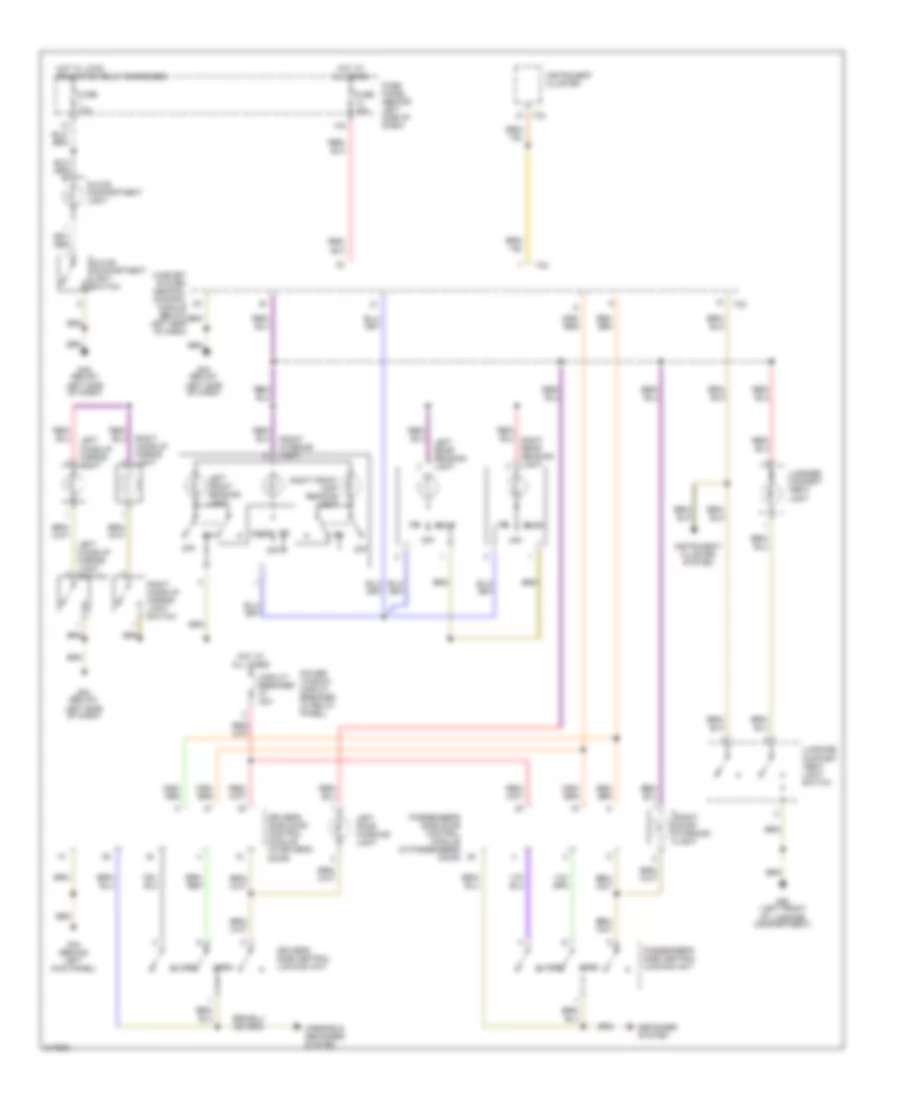 https://portal-diagnostov.com/license.html
Automotive Electricians Portal FZCO
Automotive Electricians Portal FZCO
https://portal-diagnostov.com/license.html
https://portal-diagnostov.com/license.html
Automotive Electricians Portal FZCO
Automotive Electricians Portal FZCOList of elements for Courtesy Lamps Wiring Diagram, Early Production for Volkswagen GTI 2006:
- 14a
- Circuit breaker 30a
- Close
- Comfort system central control module (below left side of dash)
- Defogger system
- Door
- Driver's side central locking unit
- Driver's side door control module (in driver's door)
- Front interior light
- Fuse 10a
- Fuse panel (behind left side of dash)
- G42 (below left side of dash)
- G44 (behind left kick panel)
- G50 (left front of luggage compartment)
- Glove compartment light
- Glove compartment light switch
- Hot at all times
- Hot w/ load reduction relay energized
- Instrument cluster
- Instrument cluster system
- Left door warning light
- Left front reading light
- Left make-up mirror light
- Left make-up mirror light switch
- Left rear reading light
- Luggage compart -ment light
- Luggage compart -ment light switch
- Mirrors & defogger system
- Off
- Open
- Passenger's side central locking unit
- Passenger's side door control module (in passenger's door)
- Power window circuit breaker (in relay panel)
- Right door warning light
- Right front map/ reading light
- Right make-up mirror light
- Right make-up mirror light switch
- T23
- T32
Courtesy Lamps Wiring Diagram, Late Production (1 of 2) for Volkswagen GTI 2006
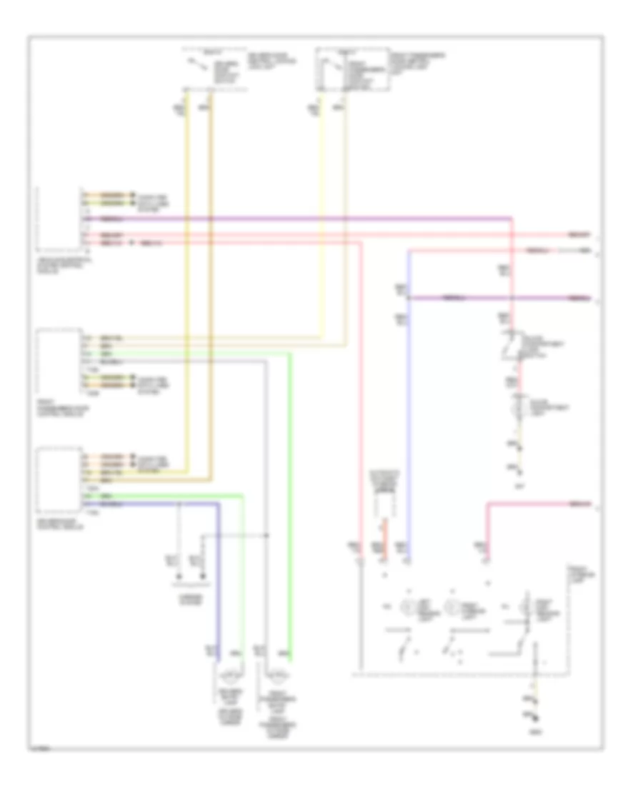 https://portal-diagnostov.com/license.html
Automotive Electricians Portal FZCO
Automotive Electricians Portal FZCO
https://portal-diagnostov.com/license.html
https://portal-diagnostov.com/license.html
Automotive Electricians Portal FZCO
Automotive Electricians Portal FZCOList of elements for Courtesy Lamps Wiring Diagram, Late Production (1 of 2) for Volkswagen GTI 2006:
- Automatic day/night interior mirror
- Computer data lines system
- Driver's door central locking lock unit
- Driver's door contact switch
- Driver's door control module
- Driver's entry lamp
- Driver's outside mirror
- Front interior lamp
- Front interior light
- Front passenger's door central locking lock unit
- Front passenger's door contact switch
- Front passenger's door control module
- Front passenger's entry lamp
- Front passenger's outside mirror
- G47
- G605
- Glove compartment lamp switch
- Glove compartment light
- Left map/ reading light
- Mirrors system
- Nca
- Right map/ reading light
- T16a
- T16d
- T20a
- T20b
- Vehicle electrical system control module
Courtesy Lamps Wiring Diagram, Late Production (2 of 2) for Volkswagen GTI 2006
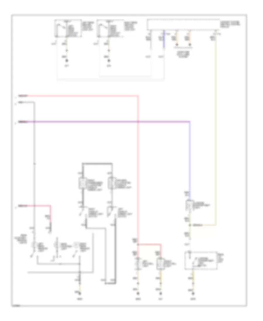 https://portal-diagnostov.com/license.html
Automotive Electricians Portal FZCO
Automotive Electricians Portal FZCO
https://portal-diagnostov.com/license.html
https://portal-diagnostov.com/license.html
Automotive Electricians Portal FZCO
Automotive Electricians Portal FZCOList of elements for Courtesy Lamps Wiring Diagram, Late Production (2 of 2) for Volkswagen GTI 2006:
- Comfort system central control module
- Computer data lines system
- Driver's illuminated make-up mirror light
- Front passenger's illuminated make-up mirror light
- G47
- G605
- G679
- G77
- G78
- Left footwell light
- Left make-up mirror light switch
- Left rear central locking lock unit
- Left rear door contact switch
- Left rear reading light
- Luggage compartment light
- Luggage compartment light switch
- Nca
- Rear courtesy light
- Rear courtesy/ reading lights
- Rear lid lock unit
- Right footwell light
- Right make-up mirror light switch
- Right rear central locking lock unit
- Right rear door contact switch
- Right rear reading light
- T18
- T18a
Instrument Illumination Wiring Diagram, Early Production for Volkswagen GTI 2006
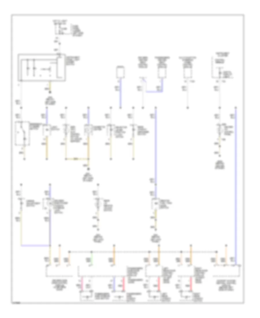 https://portal-diagnostov.com/license.html
Automotive Electricians Portal FZCO
Automotive Electricians Portal FZCO
https://portal-diagnostov.com/license.html
https://portal-diagnostov.com/license.html
Automotive Electricians Portal FZCO
Automotive Electricians Portal FZCOList of elements for Instrument Illumination Wiring Diagram, Early Production for Volkswagen GTI 2006:
- (5)
- Cigarette lighter
- Comfort system central control module (behind left side of dash)
- Control module
- Digital display light
- Driver's heated seat control module
- Driver's side door control module (in driver's door)
- Driver's side power window/ interior lock switch
- Emergency flasher switch
- Esp/ anti- slip control switch (w/ acs or esp/asc)
- Fuse 5a
- Fuse panel (under left side of dash)
- G206 (behind center of dash)
- G42 (below left side of dash)
- G44 (behind left kick panel)
- Heater- a/c control panel
- Hot w/ light switch on
- Instrument cluster
- Instrument panel light dimmer switch
- Left rear door control module (in left rear door)
- Left rear window switch
- Light switch
- Mirror adjustment switch
- Multi-function steering wheel control module
- Passenger's heated seat control module
- Passenger's side door control module (in passenger's door)
- Passenger's side interior lock switch
- Passenger's side window switch
- Radio
- Rear lid remote unlock switch
- Rear window defogger switch
- Red
- Remote/ fuel tank door switch
- Right rear door control module (in right rear door)
- Right rear window switch
- Selector lever position illumi- nation
- T18c
- T23
- T32
- T8b
Instrument Illumination Wiring Diagram, Late Production (1 of 2) for Volkswagen GTI 2006
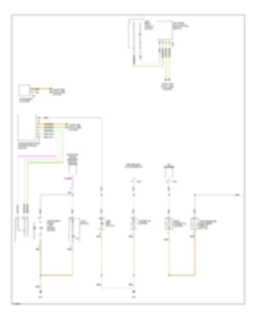 https://portal-diagnostov.com/license.html
Automotive Electricians Portal FZCO
Automotive Electricians Portal FZCO
https://portal-diagnostov.com/license.html
https://portal-diagnostov.com/license.html
Automotive Electricians Portal FZCO
Automotive Electricians Portal FZCOList of elements for Instrument Illumination Wiring Diagram, Late Production (1 of 2) for Volkswagen GTI 2006:
- (8)
- Asr/ esp switch
- Cd changer
- Cigarette lighter
- Computer data lines system
- G47
- Heater/heat output switch
- Instrument cluster
- Instrument panel lamp dimmer switch
- Left rear door control module
- Left rear window switch
- Light switch
- Rear cigarette lighter
- Selector lever sensors control module
- T12d
- T18c
- T20c
- T36
- Tire pressure monitoring display button
- Vehicle electrical system control module
Instrument Illumination Wiring Diagram, Late Production (2 of 2) for Volkswagen GTI 2006
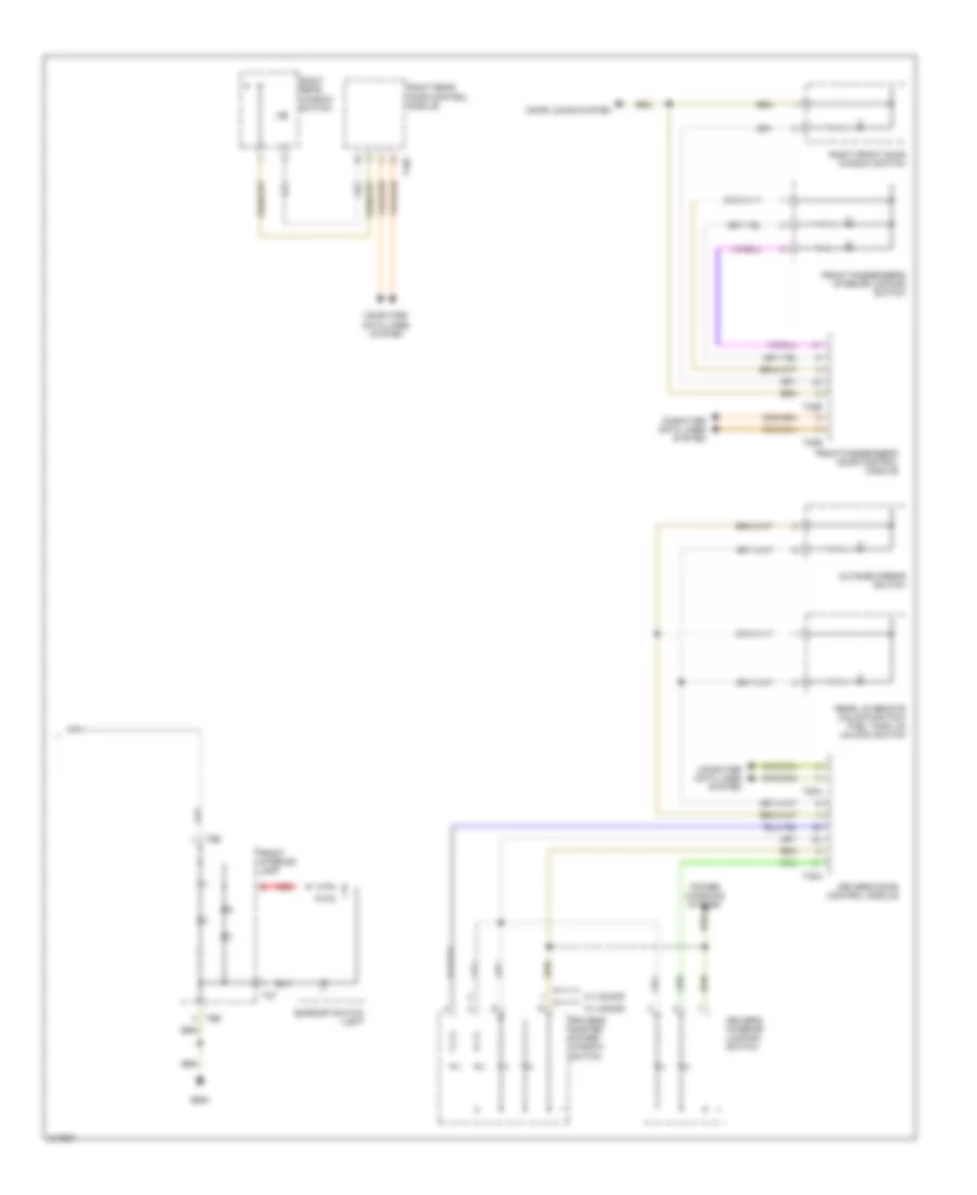 https://portal-diagnostov.com/license.html
Automotive Electricians Portal FZCO
Automotive Electricians Portal FZCO
https://portal-diagnostov.com/license.html
https://portal-diagnostov.com/license.html
Automotive Electricians Portal FZCO
Automotive Electricians Portal FZCOList of elements for Instrument Illumination Wiring Diagram, Late Production (2 of 2) for Volkswagen GTI 2006:
- Computer data lines system
- Door locks system
- Driver's door control module
- Driver's interior locking switch
- Driver's master power window switch
- Front interior lamp
- Front passenger's door control module
- Front passenger's interior locking switch
- G605
- Outside mirror switch
- Power windows system
- Rear lid remote unlock switch/ fuel tank lid unlock switch
- Red
- Right front door window switch
- Right rear door control module
- Right rear window switch
- Sunroof switch light
- T18c
- T20a
- T20b
- T2t
- T32a
- T32b
- T6b
- W/ 2-door
- W/ 4-door
NAVIGATION
Compass Wiring Diagram for Volkswagen GTI 2006
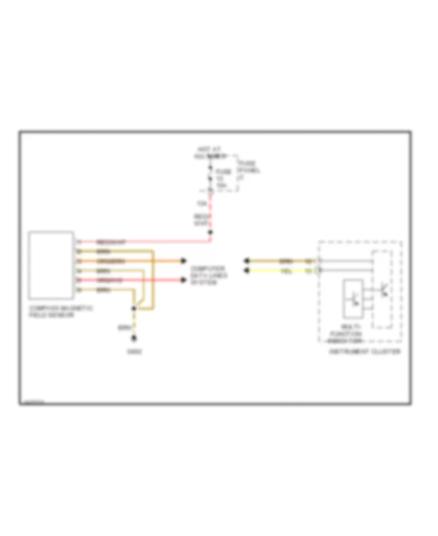 https://portal-diagnostov.com/license.html
Automotive Electricians Portal FZCO
Automotive Electricians Portal FZCO
https://portal-diagnostov.com/license.html
https://portal-diagnostov.com/license.html
Automotive Electricians Portal FZCO
Automotive Electricians Portal FZCOList of elements for Compass Wiring Diagram for Volkswagen GTI 2006:
- 13a
- Compass magnetic field sensor
- Computer data lines system
- Fuse 10a
- Fuse panel c
- G662
- Hot at all times
- Instrument cluster
- Multi- function indicator
Navigation Wiring Diagram (1 of 2) for Volkswagen GTI 2006
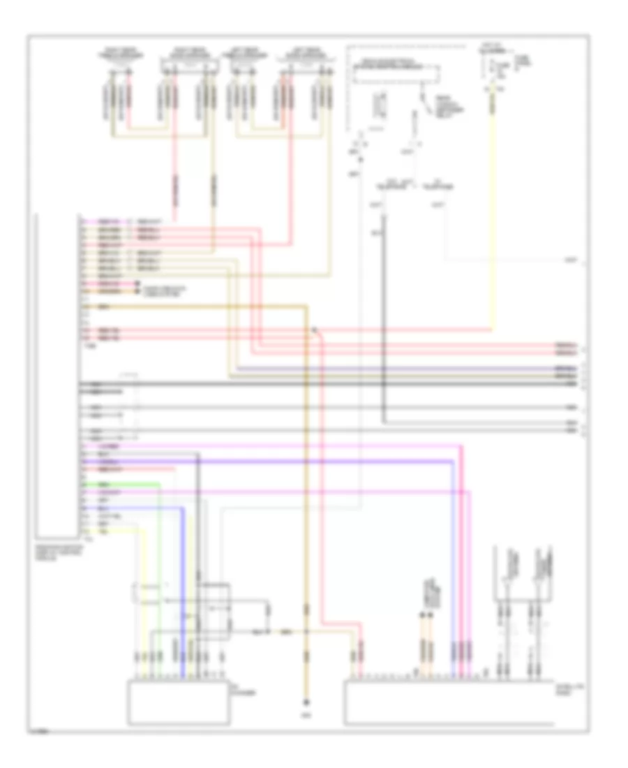 https://portal-diagnostov.com/license.html
Automotive Electricians Portal FZCO
Automotive Electricians Portal FZCO
https://portal-diagnostov.com/license.html
https://portal-diagnostov.com/license.html
Automotive Electricians Portal FZCO
Automotive Electricians Portal FZCOList of elements for Navigation Wiring Diagram (1 of 2) for Volkswagen GTI 2006:
- Cd changer
- Computer data lines system
- Fuse 15a
- Fuse panel b
- G45
- Hot at all times
- Left rear bass speaker
- Left rear treble speaker
- Nca
- Radio/navigation display control module
- Rear window defogger relay
- Right rear bass speaker
- Right rear treble speaker
- Satellite
- Satellite antenna
- Satellite radio
- T12
- T16b
- T8a
- T8b
- Tuner antenna
- Vehicle electrical system control module
- W/ telephone
- W/o telephone
Navigation Wiring Diagram (2 of 2) for Volkswagen GTI 2006
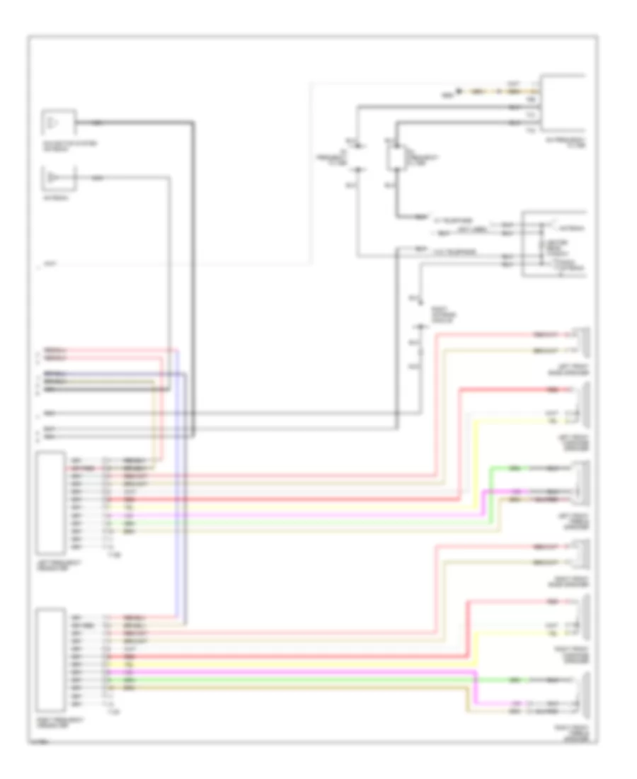 https://portal-diagnostov.com/license.html
Automotive Electricians Portal FZCO
Automotive Electricians Portal FZCO
https://portal-diagnostov.com/license.html
https://portal-diagnostov.com/license.html
Automotive Electricians Portal FZCO
Automotive Electricians Portal FZCOList of elements for Navigation Wiring Diagram (2 of 2) for Volkswagen GTI 2006:
- (not used)
- Am frequency filter
- Antenna
- Fm frequency filter
- G662
- Heated rear window
- Left frequency crossover
- Left front bass speaker
- Left front midrange speaker
- Left front treble speaker
- Navigation system antenna
- Nca
- Radio antenna
- Red
- Right antenna module
- Right frequency crossover
- Right front bass speaker
- Right front midrange speaker
- Right front treble speaker
- T12e
- T12f
- T1c
- T1d
- T2b
- W/ telephone
- W/o telephone
POWER DISTRIBUTION
Power Distribution Wiring Diagram, Early Production (1 of 3) for Volkswagen GTI 2006
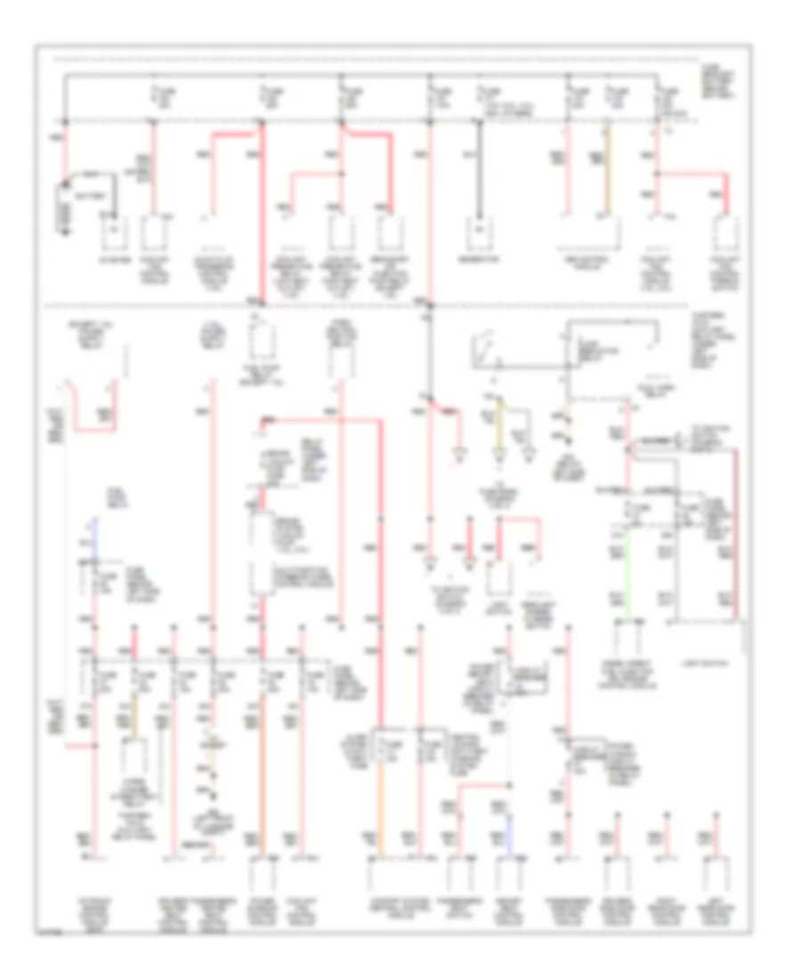 https://portal-diagnostov.com/license.html
Automotive Electricians Portal FZCO
Automotive Electricians Portal FZCO
https://portal-diagnostov.com/license.html
https://portal-diagnostov.com/license.html
Automotive Electricians Portal FZCO
Automotive Electricians Portal FZCOList of elements for Power Distribution Wiring Diagram, Early Production (1 of 3) for Volkswagen GTI 2006:
- (2.0l, 3.2l) (others)
- 12v socket
- 16a
- 28a
- 30a
- 33a
- 35a
- 36a
- 37a
- 44a
- 75x
- Abs control module
- Alarm system & anti- theft fuse
- Battery
- Brake system vacuum pump (1.8l, 2.0l)
- Brake vacuum pump fuse 20a
- Central locking/ anti-theft warning system fuse
- Circuit breaker 30a
- Comfort system central control module
- Coolant fan control module
- Coolant fan control module (1.9l, 2.0l)
- Coolant fan control thermal switch
- Coolant preheating relay (high heat outlet) (1.9l)
- Coolant preheating relay (low heat outlet) (1.9l)
- Diesel direct fuel injection (dfi) engine control module
- Driver's heated seat control module
- Driver's side door control module
- Dual horn relay
- Fuel pump relay
- Fuel pump relay (except 1.9l)
- Fuse 10a
- Fuse 110a
- Fuse 110a 150a
- Fuse 15a
- Fuse 20a
- Fuse 30a
- Fuse 30a (or 40a)
- Fuse 40a
- Fuse 50a
- Fuse 5a
- Fuse bracket/ battery (behind battery)
- Fuse panel (behind left side of dash)
- G42 (below left side of dash)
- G50 (left front of luggage compt)
- Generator
- Glow plug triggering control module (1.9l)
- Headlight dimmer/ flasher switch
- Left rear door control module
- Light switch
- Load reduction relay
- Memory seat control module
- Motronic engine control module (ecm)
- Multi-function steering wheel control module
- Park/ neutral position relay
- Passenger's heated seat control module
- Passenger's seat switch
- Passenger's side door control module
- Power memory seat circuit breaker (in relay panel)
- Power sunroof control module
- Power window circuit breaker (in relay panel)
- Red
- Red red
- Relay panel (under left side of dash)
- Right rear door control module
- Secondary air injection pump relay (except 1.9l)
- Starter
- T14
- T15
- T2b
- T4a
- T60
- T6f
- T8f
- Thirteen -fold auxiliary relay panel
- Thirteen -fold auxiliary relay panel (under left side of dash)
- To fuse panel (diagram 3 of 3)
- To ignition switch (diagram 2 of 3)
- Wiper/ washer intermittent relay
Power Distribution Wiring Diagram, Early Production (2 of 3) for Volkswagen GTI 2006
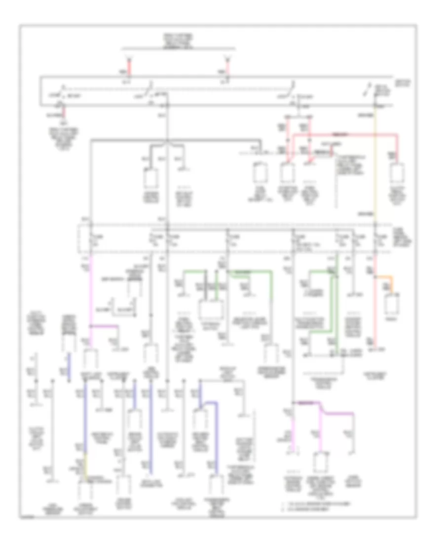 https://portal-diagnostov.com/license.html
Automotive Electricians Portal FZCO
Automotive Electricians Portal FZCO
https://portal-diagnostov.com/license.html
https://portal-diagnostov.com/license.html
Automotive Electricians Portal FZCO
Automotive Electricians Portal FZCOList of elements for Power Distribution Wiring Diagram, Early Production (2 of 3) for Volkswagen GTI 2006:
- (1.9l)
- (4-spd)
- (4-spd) (5-spd)
- (5-spd)
- (canada) (exc canada)
- (exc 1.9l)
- (not used)
- 1.8l & 2.0l engine code avh & bev
- 10a
- 11a
- 2.0l engine code bbw
- 29a
- 31a
- 50b
- 75x
- 86s
- A/t
- Abs control module
- Air bag control module
- Airbag spiral spring/ return spring
- Anti-slip control switch (w/ asc)
- Automatic day/night interior mirror
- Back-up light switch (m/t)
- Brake vacuum vent valve switch
- Clutch pedal position switch (m/t)
- Clutch vacuum vent valve switch (m/t)
- Comfort system central control module
- Coolant fan control module
- Cruise control switch
- Data link connector
- Daytime running lights change -over relay
- Diesel direct fuel injection (dfi) engine control module (ecm) (1.9l)
- Driver's heated seat control module
- Esp switch
- From thirteen -fold auxiliary relay panel (diagram 1 of 3)
- From thirteen -fold auxiliary relay panel (splice) (diagram 1 of 3)
- Fuel pump relay (except 1.9l)
- Fuse 10a
- Fuse 15a
- Fuse 20a
- Fuse 5a
- Fuse 7.5a
- Fuse panel (behind left side of dash)
- Heater-a/c control panel
- High pressure sensor
- Ignition switch
- Instrument cluster
- Key-in ignition switch
- Lock
- M/t
- Mass air flow sensor
- Mirror adjustment switch
- Motronic engine control module
- Multi- function steering wheel control module
- Multi-function transmission range switch
- Nca
- Park neutral position relay (a/t)
- Park/ neutral position relay
- Passenger's heated seat control module
- Radio
- Red
- Selector lever position warning light (p/n)
- Shift lock solenoid
- Speedometer vehicle speed sensor
- Start
- Starting interlock relay (m/t)
- Steering angle sensor
- T14
- T23
- T32
- T68 t68a
- T8b
- T94
- Thirteen -fold auxiliary relay panel (under left side of dash)
- Thirteenfold auxiliary relay panel (under left side of dash)
- Tiptronic switch
- Transmission control module
Power Distribution Wiring Diagram, Early Production (3 of 3) for Volkswagen GTI 2006
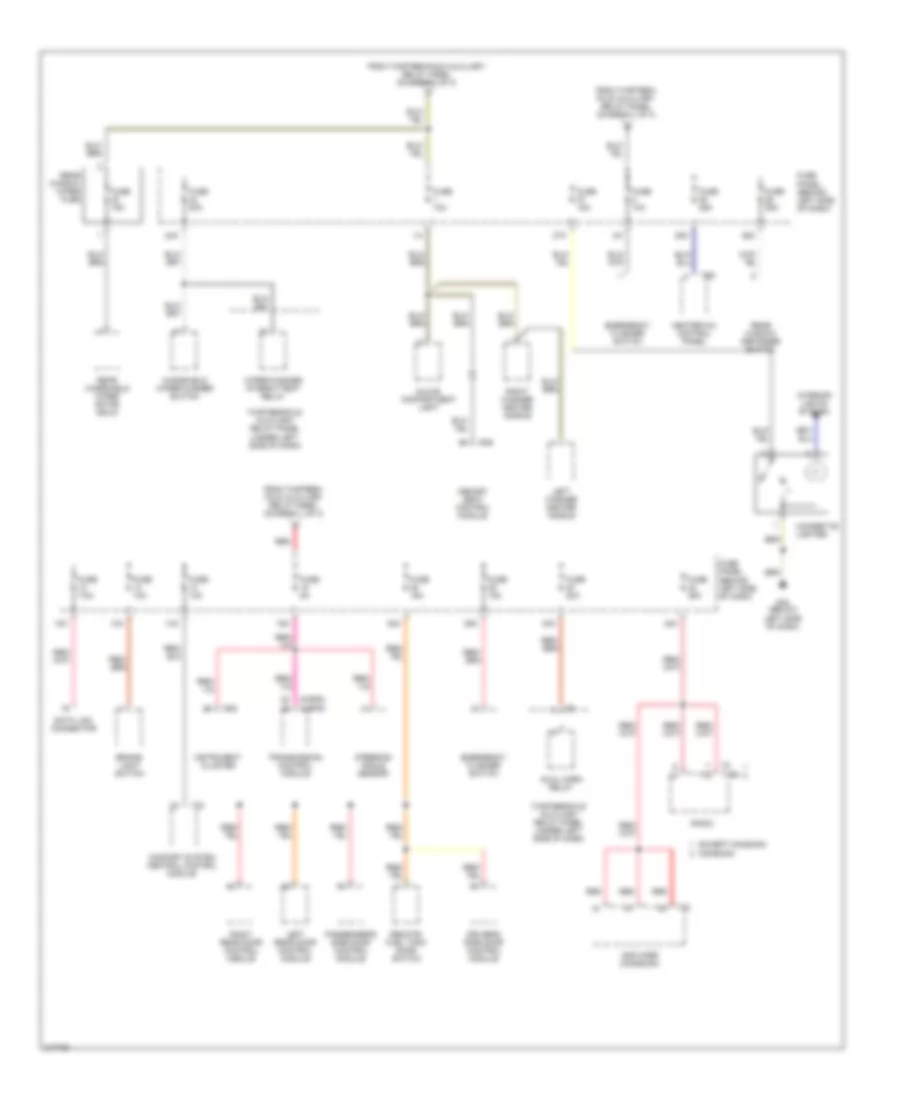 https://portal-diagnostov.com/license.html
Automotive Electricians Portal FZCO
Automotive Electricians Portal FZCO
https://portal-diagnostov.com/license.html
https://portal-diagnostov.com/license.html
Automotive Electricians Portal FZCO
Automotive Electricians Portal FZCOList of elements for Power Distribution Wiring Diagram, Early Production (3 of 3) for Volkswagen GTI 2006:
- (4-spd)
- (5-spd)
- 12a
- 13a
- 14a
- 15a
- 24a
- 25a
- 26a
- 27a
- 38a
- 39a
- 40a
- 42a
- Amplifier (monsoon)
- Brake- light switch
- Cigarette lighter
- Comfort system central control module
- Data link connector
- Driver's side door control module
- Dual horn relay
- Emergency flasher switch
- Except monsoon
- From thirteen- fold auxiliary relay panel (diagram 1 of 3)
- From thirteen-fold auxiliary relay panel (diagram 1 of 3)
- Fuse 10a
- Fuse 15a
- Fuse 20a
- Fuse 25a
- Fuse 5a
- Fuse 7.5a
- Fuse panel (behind left side of dash)
- G42 (below left side of dash)
- Glove compartment light
- Heater-a/c control panel
- Instrument cluster
- Interior lights system
- Left rear door control module
- Left washer heater nozzle
- Memory seat control module
- Monsoon
- Passenger's side door control module
- Radio
- Rear window defogger switch
- Rear window wiper fuse
- Rear windshield wiper motor (golf)
- Red
- Remote/ fuel tank door switch
- Right rear door control module
- Right washer heater nozzle
- Steering angle sensor
- T23
- T28
- T32
- T6d
- T8 t16d
- Thirteenfold auxiliary relay panel (under left side of dash)
- Transmission control module
- Windshield wiper/washer switch
- Wiper/washer intermittent relay
Power Distribution Wiring Diagram, Late Production (1 of 4) for Volkswagen GTI 2006
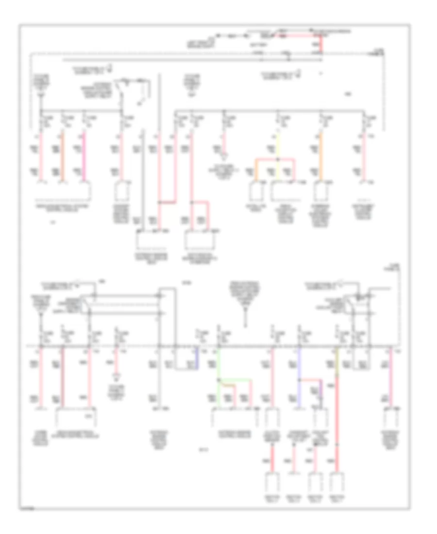 https://portal-diagnostov.com/license.html
Automotive Electricians Portal FZCO
Automotive Electricians Portal FZCO
https://portal-diagnostov.com/license.html
https://portal-diagnostov.com/license.html
Automotive Electricians Portal FZCO
Automotive Electricians Portal FZCOList of elements for Power Distribution Wiring Diagram, Late Production (1 of 4) for Volkswagen GTI 2006:
- (diagram 2 of 4)
- A/30
- A68
- A81
- A98
- Auxiliary engine coolant pump relay
- B110
- B138
- B156
- Battery
- Camshaft adjustment valve 1
- Clutch position sensor
- Comfort system central control module
- Coolant fan control module
- D78
- Data bus on board diagnostic interface
- From fuse panel b (diagram 1 of 4)
- Fuse 10a
- Fuse 15a
- Fuse 20a
- Fuse 25a
- Fuse 30a
- Fuse 40a
- Fuse 50a
- Fuse 5a
- Fuse panel b
- G12 (left front of engine compt)
- Ignition coil 1
- Ignition coil 2
- Ignition coil 3
- Ignition coil 4
- Instrument cluster control module
- L/30
- M/30
- Motronic engine control module
- Motronic engine control module (ecm)
- Radio/ navigation display control module
- Red
- Satellite radio
- Starting/charging system
- Steering column electronic systems control module
- T16b
- T18
- T20d
- T26
- T36
- T40
- T8b
- T94
- To fuse panel a (diagram 2 of 4)
- To fuse panel b (diagram 1 of 4)
- To fuse panel b (diagram 2 of 4)
- To fuse panel b e
- To fuse panel b f
- To fuse panel c (diagram 3 of 4)
- Vehicle electrical system control module
- Wiper motor control module
Power Distribution Wiring Diagram, Late Production (2 of 4) for Volkswagen GTI 2006
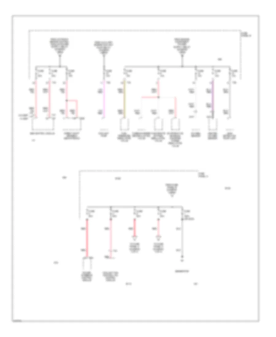 https://portal-diagnostov.com/license.html
Automotive Electricians Portal FZCO
Automotive Electricians Portal FZCO
https://portal-diagnostov.com/license.html
https://portal-diagnostov.com/license.html
Automotive Electricians Portal FZCO
Automotive Electricians Portal FZCOList of elements for Power Distribution Wiring Diagram, Late Production (2 of 4) for Volkswagen GTI 2006:
- A68
- A81
- A98
- Abs control module
- B110
- B138
- B156
- Coolant fan control (fc) control module
- Coolant pump
- D78
- Direct shift gearbox mechatronic
- Evaporative emission canister purge regulator valve
- From auxiliary engine coolant pump relay diagram (1 of 4)
- From fuse panel b diagram (1 of 4)
- Fuel pressure regulator valve
- Fuse 10a
- Fuse 150a (or 200a)
- Fuse 15a
- Fuse 30a
- Fuse 50a
- Fuse 80a
- Fuse panel a
- Fuse panel b
- Generator
- Heated oxygen sensor
- Leak detection pump (ldp)
- Nca
- Oxygen sensor
- Power steering control module
- Red
- T20e
- T26
- T2a
- T40
- T47
- T4x
- To fuse panel c (diagram 3 of 4)
- Turbocharger recirculating valve
- W/ esp
- W/o esp
- Wastegate bypass regulator valve
Power Distribution Wiring Diagram, Late Production (3 of 4) for Volkswagen GTI 2006
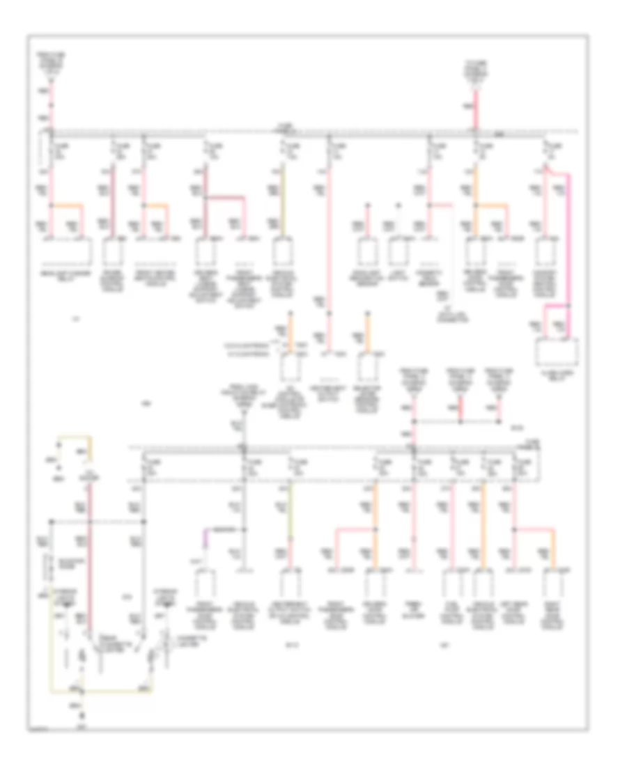 https://portal-diagnostov.com/license.html
Automotive Electricians Portal FZCO
Automotive Electricians Portal FZCO
https://portal-diagnostov.com/license.html
https://portal-diagnostov.com/license.html
Automotive Electricians Portal FZCO
Automotive Electricians Portal FZCOList of elements for Power Distribution Wiring Diagram, Late Production (3 of 4) for Volkswagen GTI 2006:
- 12a
- 12v socket
- 13a
- 14a
- 15a
- 17a
- 22a
- 23a
- 25a
- 26a
- 27a
- 32a
- 33a
- 36a
- 37a
- 40a
- 42a
- A/c control module or climatronic control module
- A68
- A81
- A98
- Alarm horn relay
- B110
- B138
- B156
- Blocking diode
- Cigarette lighter
- Comfort system central control module
- D78
- Data link connector
- Driver's door control module
- Driver's seat lumbar support adjustment switch
- Fresh air blower
- From fuse panel a (diagram 2 of 4)
- From fuse panel b (diagram 1 of 4)
- From fuse panel c (diagram 3 of 4)
- From load induction relay (diagram 4 of 4)
- Front heated seats control module
- Front passenger's door control module
- Front passenger's seat lumbar support adjustment switch
- Fuel pump control module
- Fuse 10a
- Fuse 15a
- Fuse 20a
- Fuse 25a
- Fuse 30a
- Fuse 40a
- Fuse 5a
- Fuse 7.5a
- Fuse panel c
- G47
- G682
- Headlamp washer relay
- Heater/heat output switch
- Heater/heat output switch or a/c control module
- Interior lights system
- Left rear door control module
- Light switch
- Magnetic field sensor
- Power sunroof control module
- Rain/light recognition sensor
- Rear cigarette lighter
- Red
- Right rear door control module
- Selector lever sensors control module
- T10h
- T10n
- T18
- T18c
- T18d
- T20a
- T20b
- T20c
- T6ah
- T6ai
- T6c
- T8z
- To fuse panel c (diagram 3 of 4)
- Vehicle electrical system control module
- W/ climatronic
- W/o climatronic
Power Distribution Wiring Diagram, Late Production (4 of 4) for Volkswagen GTI 2006
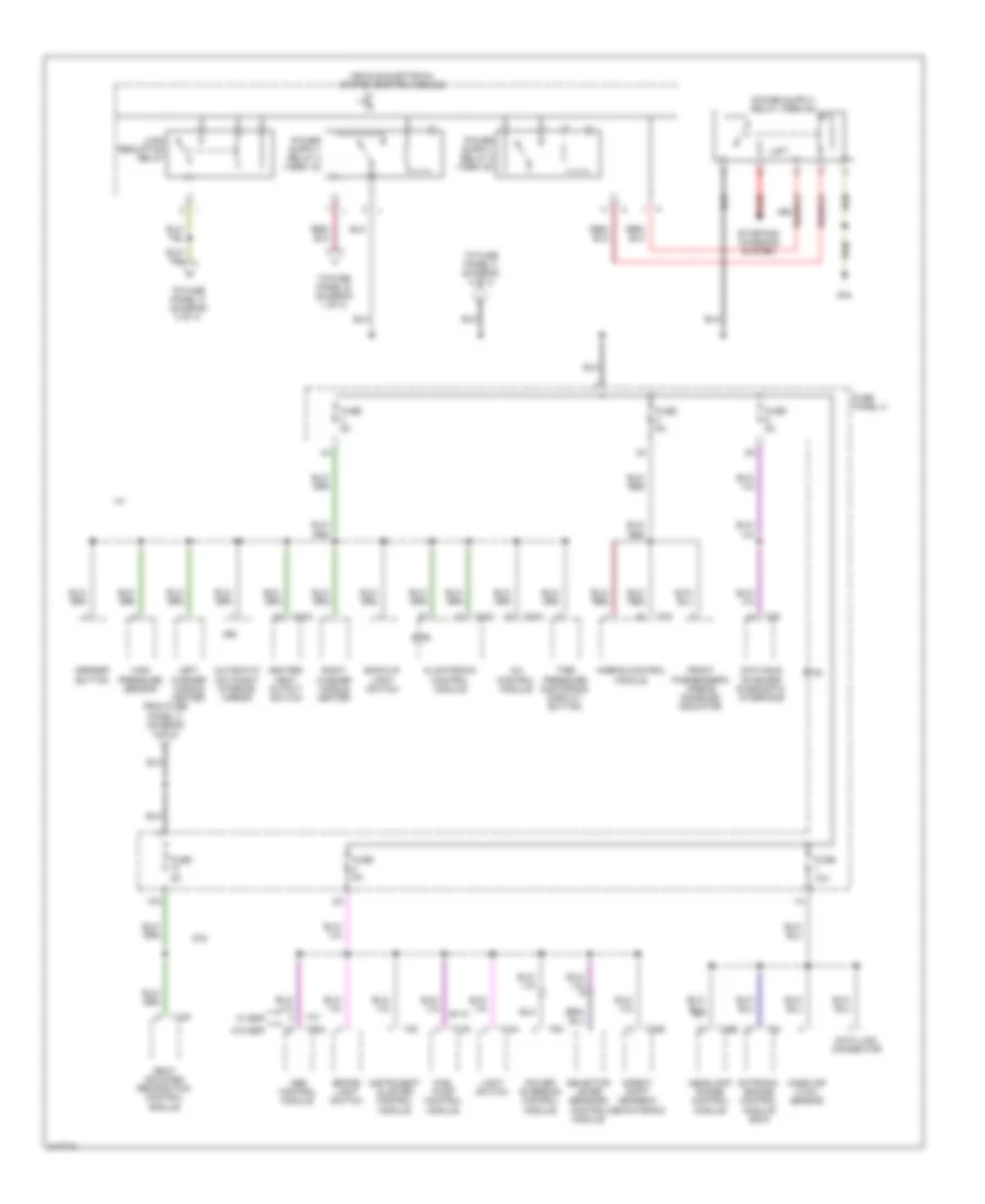 https://portal-diagnostov.com/license.html
Automotive Electricians Portal FZCO
Automotive Electricians Portal FZCO
https://portal-diagnostov.com/license.html
https://portal-diagnostov.com/license.html
Automotive Electricians Portal FZCO
Automotive Electricians Portal FZCOList of elements for Power Distribution Wiring Diagram, Late Production (4 of 4) for Volkswagen GTI 2006:
- 10a
- A/c control module
- A68
- A81
- A98
- Abs control module
- Airbag control module
- Asr/esp button
- Automatic day/night interior mirror
- B110
- B138
- B156
- Back-up light switch
- Brake light switch
- Climatronic control module
- D78
- Data bus on board diagnostic interface
- Data link connector
- Direct shift gearbox mechatronic
- From fuse panel c (diagram 4 of 4)
- Front passenger's airbag disabled indicator
- Fuel pump control module
- Fuse 10a
- Fuse 5a
- Fuse panel c
- G44
- Headlamp range control module
- Heater/ heat output switch
- High pressure sensor
- Instrument cluster control module
- Left washer nozzle heater
- Light switch
- Load reduction relay
- Mass air flow sensor
- Motronic engine control module (ecm)
- Power steering control module
- Red
- Right washer nozzle heater
- Seat occupied recognition control module
- Selector lever sensors control module
- Starting/ charging system
- T10h
- T10n
- T18f
- T20
- T20c
- T20e
- T26a
- T26b
- T36
- T47
- T5h
- T75
- T94
- Tire pressure monitoring display button
- To fuse panel b (diagram 1 of 4)
- To fuse panel c (diagram 3 of 4)
- To fuse panel c (diagram 4 of 4)
- Vehicle electrical system control module
- W/ esp
- W/o esp
POWER DOOR LOCKS
Power Door Locks Wiring Diagram, Early Production (1 of 2) for Volkswagen GTI 2006
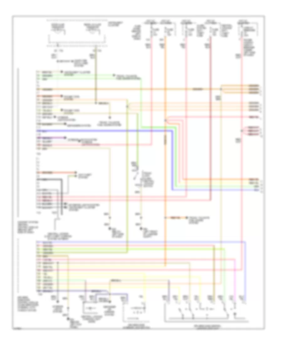 https://portal-diagnostov.com/license.html
Automotive Electricians Portal FZCO
Automotive Electricians Portal FZCO
https://portal-diagnostov.com/license.html
https://portal-diagnostov.com/license.html
Automotive Electricians Portal FZCO
Automotive Electricians Portal FZCOList of elements for Power Door Locks Wiring Diagram, Early Production (1 of 2) for Volkswagen GTI 2006:
- 14a
- 38a
- Alarm system anti- theft fuse
- Anti-theft system
- Central locking & anti-theft warning system antenna
- Central locking warning light (safe)
- Central locking/ anti- theft fuse
- Circuit breaker 30a
- Comfort system central control module (behind left side of dash)
- Computer data lines system
- Defogger or mirrors system
- Defoggers system
- Door ajar indicator
- Driver's side central locking lock unit
- Driver's side door control module (in driver's door, integral with window motor)
- Driver's side interior lock switch
- Exterior lights system, instrument cluster system
- Fuse 10a
- Fuse 15a
- Fuse panel (behind left side of dash)
- G42 (below left side of dash)
- G44 (behind left kick panel)
- G50 (left front of luggage compt)
- Hot at all times
- Instrument cluster
- Instrument cluster system
- Interior lights system
- Nca
- Power tops system
- Power window circuit breaker (under left side of dash)
- Rear lid ajar indicator
- T15
- T23
- T29
- T32
- Trunk lock alarm/ central locking switch
- Trunk, tailgate fuel doors system
- Trunk, tailgate, fuel doors system
Power Door Locks Wiring Diagram, Early Production (2 of 2) for Volkswagen GTI 2006
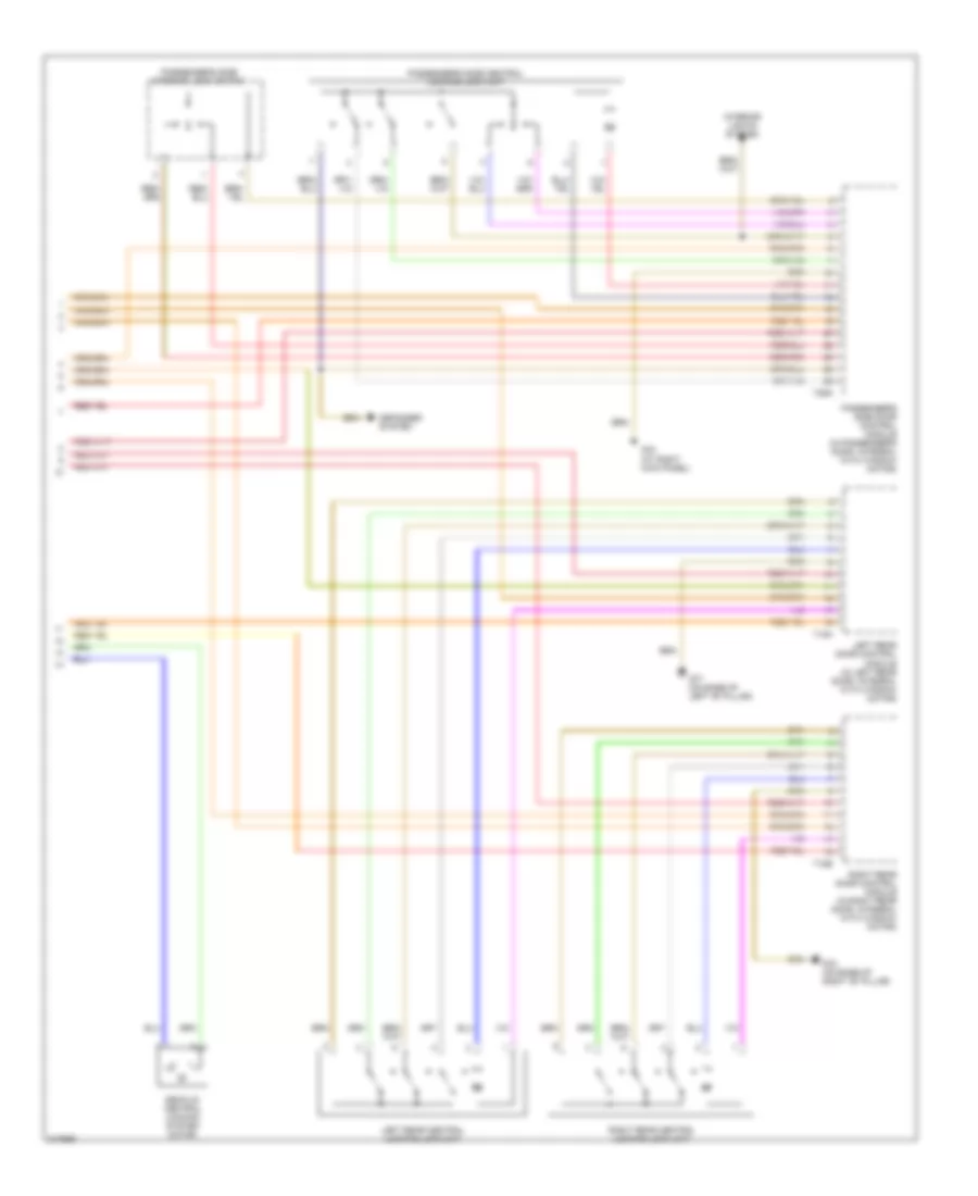 https://portal-diagnostov.com/license.html
Automotive Electricians Portal FZCO
Automotive Electricians Portal FZCO
https://portal-diagnostov.com/license.html
https://portal-diagnostov.com/license.html
Automotive Electricians Portal FZCO
Automotive Electricians Portal FZCOList of elements for Power Door Locks Wiring Diagram, Early Production (2 of 2) for Volkswagen GTI 2006:
- Decklid central locking system motor
- Defogger system
- G43 (at right kick panel)
- G77 (on base of left "b" pillar)
- G78 (on base of right "b" pillar)
- Interior lights system
- Left rear central locking lock unit
- Left rear door control module (in left rear door, integral with window motor)
- Passenger's side central locking lock unit
- Passenger's side door control module (in passenger's door, integral with window motor)
- Passenger's side interior lock switch
- Right rear central locking lock unit
- Right rear door control module (in right rear door, integral with window motor)
- T18a
- T18b
- T29a
Power Door Locks Wiring Diagram, Late Production (1 of 2) for Volkswagen GTI 2006
 https://portal-diagnostov.com/license.html
Automotive Electricians Portal FZCO
Automotive Electricians Portal FZCO
https://portal-diagnostov.com/license.html
https://portal-diagnostov.com/license.html
Automotive Electricians Portal FZCO
Automotive Electricians Portal FZCOList of elements for Power Door Locks Wiring Diagram, Late Production (1 of 2) for Volkswagen GTI 2006:
- 12a
- 17a
- 26a
- Computer data lines system
- Driver's central locking safe indicator lamp
- Driver's door central locking lock unit
- Driver's door control module
- Driver's interior lock switch
- Front passenger's central locking safe indicator lamp
- Front passenger's door central locking lock unit
- Front passenger's door control module
- Front passenger's interior lock switch
- Fuse 10a
- Fuse 30a
- Fuse 5a
- Fuse panel c
- G44
- G47
- G77
- G78
- Hot at all times
- Interior lights system
- Left rear door control module
- Left rear interior lock switch
- Nca
- Right rear door control module
- Right rear interior lock switch
- T20a
- T20b
- T32a
- T32b
Power Door Locks Wiring Diagram, Late Production (2 of 2) for Volkswagen GTI 2006
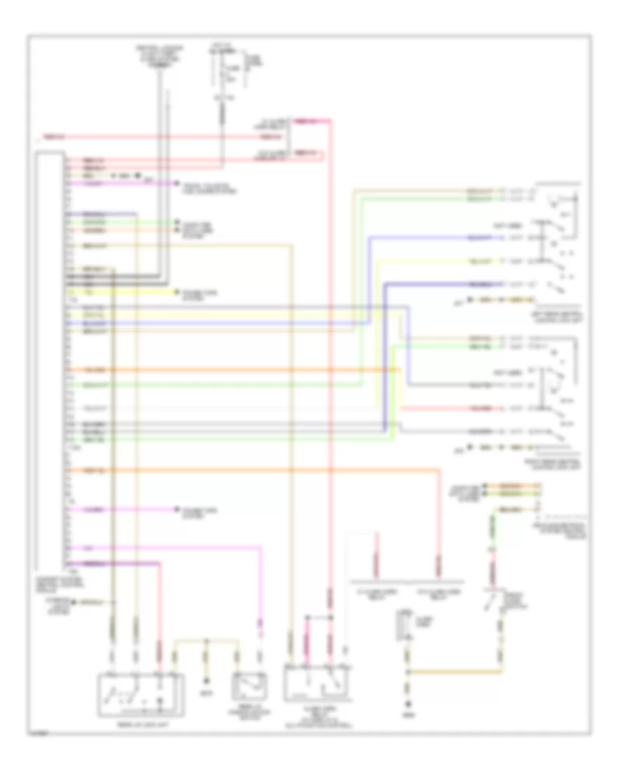 https://portal-diagnostov.com/license.html
Automotive Electricians Portal FZCO
Automotive Electricians Portal FZCO
https://portal-diagnostov.com/license.html
https://portal-diagnostov.com/license.html
Automotive Electricians Portal FZCO
Automotive Electricians Portal FZCOList of elements for Power Door Locks Wiring Diagram, Late Production (2 of 2) for Volkswagen GTI 2006:
- (not used)
- Alarm horn
- Alarm horn relay (w/ display & multifunction control)
- Central locking & anti-theft alarm system antenna
- Comfort system central control module
- Computer data lines system
- Front hood switch
- Fuse 20a
- Fuse panel b
- G47
- G656
- G679
- G77
- G78
- Hot at all times
- Interior lights system
- Left rear central locking lock unit
- Nca
- Power tops system
- Rear lid handle unlcok switch
- Rear lid lock unit
- Right rear central locking lock unit
- T18
- T18a
- T40
- T8n
- Trunk, tailgate, fuel doors system
- Vehicle electrical system control module
- W/ alarm horn relay
- W/o alarm horn relay
POWER MIRRORS
Automatic Day/Night Mirror Wiring Diagram, Early Production for Volkswagen GTI 2006
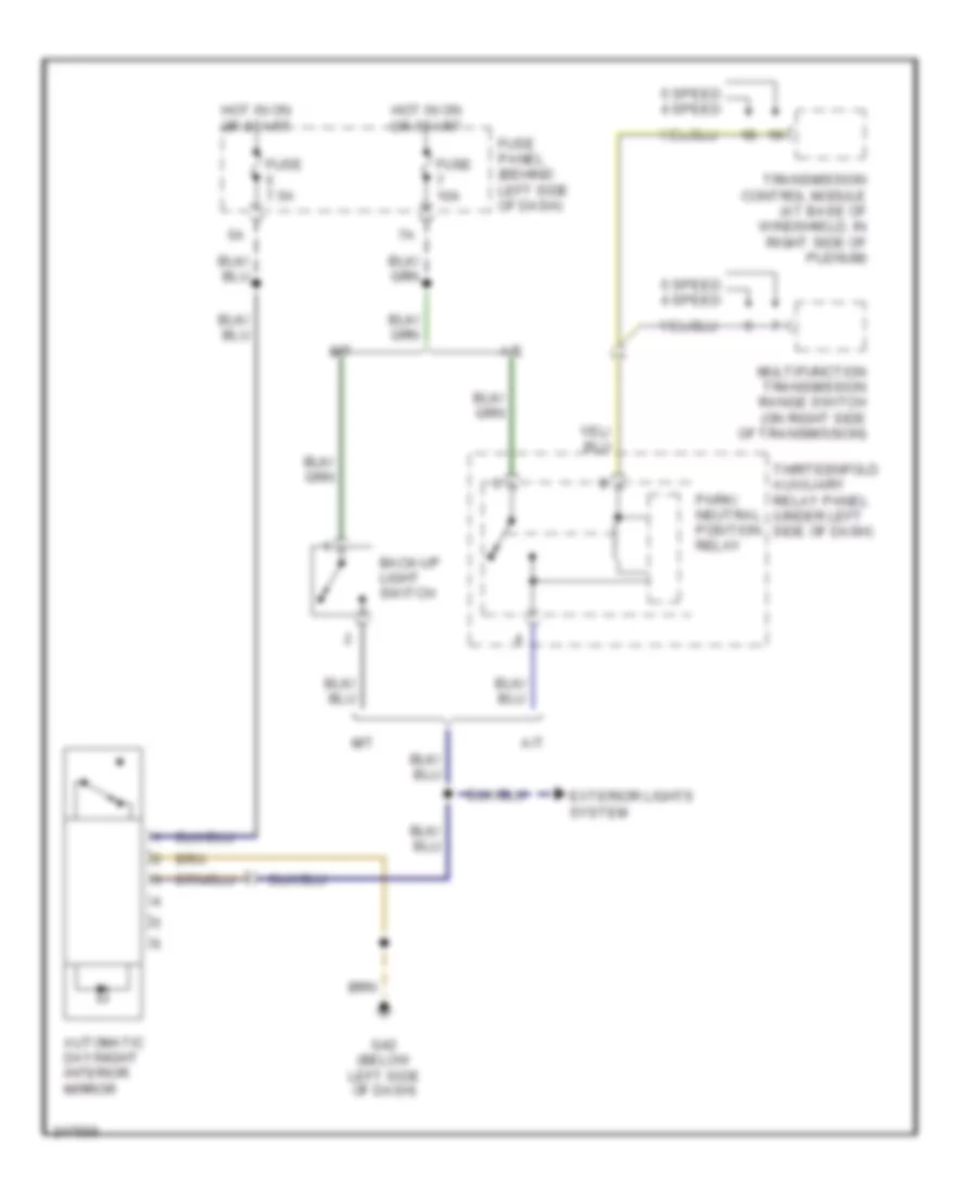 https://portal-diagnostov.com/license.html
Automotive Electricians Portal FZCO
Automotive Electricians Portal FZCO
https://portal-diagnostov.com/license.html
https://portal-diagnostov.com/license.html
Automotive Electricians Portal FZCO
Automotive Electricians Portal FZCOList of elements for Automatic Day/Night Mirror Wiring Diagram, Early Production for Volkswagen GTI 2006:
- 5 speed 4 speed
- A/t
- Automatic day/night interior mirror
- Back-up light switch
- Exterior lights system
- Fuse 10a
- Fuse 7.5a
- Fuse panel (behind left side of dash)
- G42 (below left side of dash)
- Hot in on or start
- M/t
- Multifunction transmission range switch (on right side of transmission)
- Park/ neutral position relay
- Thirteenfold auxiliary relay panel (under left side of dash)
- Transmission control module (at base of windshield, in right side of plenum)
Automatic Day/Night Mirror Wiring Diagram, Late Production for Volkswagen GTI 2006
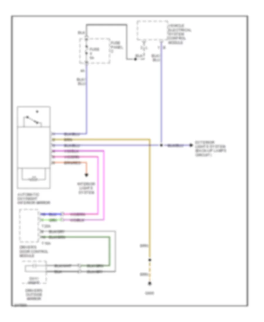 https://portal-diagnostov.com/license.html
Automotive Electricians Portal FZCO
Automotive Electricians Portal FZCO
https://portal-diagnostov.com/license.html
https://portal-diagnostov.com/license.html
Automotive Electricians Portal FZCO
Automotive Electricians Portal FZCOList of elements for Automatic Day/Night Mirror Wiring Diagram, Late Production for Volkswagen GTI 2006:
- Automatic day/night interior mirror
- Day/ night
- Driver's door control module
- Driver's outside mirror
- Exterior lights system (back-up lamps circuit)
- Fuse 5a
- Fuse panel c
- G605
- Interior lights system
- T16a
- T20a
- Vehicle electrical system control module
Power Mirrors Wiring Diagram, Early Production for Volkswagen GTI 2006
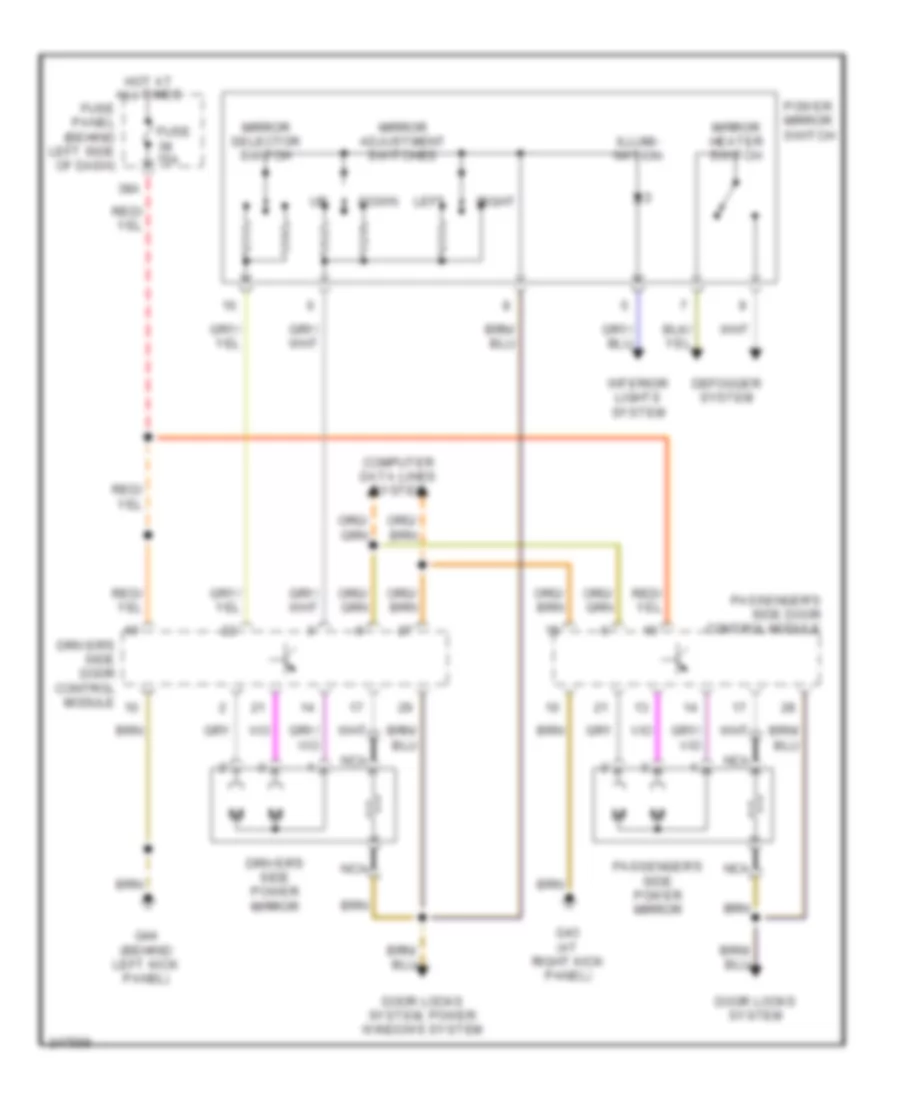 https://portal-diagnostov.com/license.html
Automotive Electricians Portal FZCO
Automotive Electricians Portal FZCO
https://portal-diagnostov.com/license.html
https://portal-diagnostov.com/license.html
Automotive Electricians Portal FZCO
Automotive Electricians Portal FZCOList of elements for Power Mirrors Wiring Diagram, Early Production for Volkswagen GTI 2006:
- 38a
- Computer data lines system
- Defogger system
- Door locks system
- Door locks system, power windows system
- Down
- Driver's side door control module
- Driver's side power mirror
- Fuse 15a
- Fuse panel (behind left side of dash)
- G43 (at right kick panel)
- G44 (behind left kick panel)
- Hot at all times
- Illumi- nation
- Interior lights system
- Left
- Mirror adjustment switches
- Mirror heater switch
- Mirror selector switch
- Nca
- Passenger's side door control module
- Passenger's side power mirror
- Power mirror switch
- Right
Power Mirrors Wiring Diagram, Late Production for Volkswagen GTI 2006
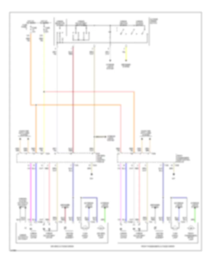 https://portal-diagnostov.com/license.html
Automotive Electricians Portal FZCO
Automotive Electricians Portal FZCO
https://portal-diagnostov.com/license.html
https://portal-diagnostov.com/license.html
Automotive Electricians Portal FZCO
Automotive Electricians Portal FZCOList of elements for Power Mirrors Wiring Diagram, Late Production for Volkswagen GTI 2006:
- 12a
- 23a
- Computer data lines system
- Defogger system
- Driver's door control module
- Driver's entry lamp
- Driver's outside mirror
- Exterior lights system
- Front passenger's door control module
- Front passenger's entry lamp
- Front passenger's outside mirror
- Fuse 10a
- Fuse 30a
- Fuse panel c
- G44
- G47
- Heated mirror element
- Hot at all times
- Interior lights system
- Mirror adjustment motor
- Mirror adjustment switches
- Mirror automatic day/night
- Mirror fold-in motor
- Mirror folding switch
- Mirror heating switch
- Mirror selector switch
- Mirrors system (automatic day/night circuit)
- Outside mirror switch
- Red
- T16a
- T16g
- T20a
- T20b
- T2ab
- T2ac
- T2ae
- T2ah
- T32a
- T3g
- T3h
- Turn signal lamp
POWER SEATS
Heated Seats Wiring Diagram, Early Production with Leather Seats for Volkswagen GTI 2006
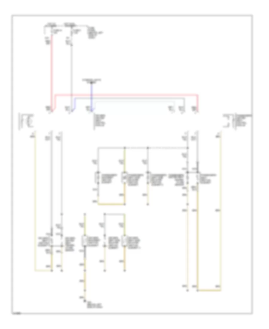 https://portal-diagnostov.com/license.html
Automotive Electricians Portal FZCO
Automotive Electricians Portal FZCO
https://portal-diagnostov.com/license.html
https://portal-diagnostov.com/license.html
Automotive Electricians Portal FZCO
Automotive Electricians Portal FZCOList of elements for Heated Seats Wiring Diagram, Early Production with Leather Seats for Volkswagen GTI 2006:
- 44a
- All times
- Driver's backrest heating element
- Driver's heated seat control module
- Driver's heated seat temper- ature sensor
- Driver's seat heating element
- Driver's seat side bolster heating element
- Driver's seat side bolster heating element 2
- Fuse 44 15a
- Fuse 5 7.5a
- Fuse panel (behind left side of dash)
- G42 (behind left side of dash)
- Hot at
- Hot in on or start
- Interior lights system
- Nca
- Passenger's backrest heating element
- Passenger's heated seat control module
- Passenger's heated seat temper- ature sensor
- Passenger's seat heating element
- Passenger's seat side bolster heating element
- Passenger's seat side bolster heating element 2
Heated Seats Wiring Diagram, Early Production without Leather Seats for Volkswagen GTI 2006
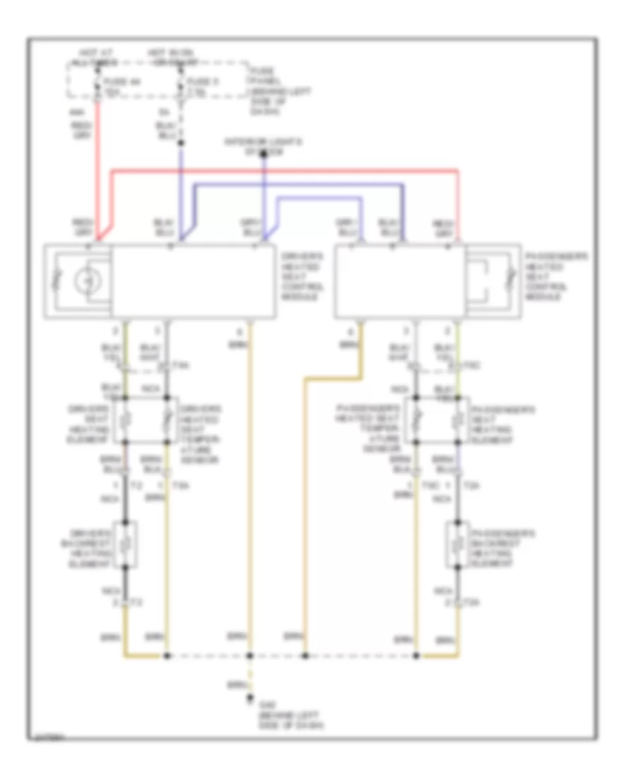 https://portal-diagnostov.com/license.html
Automotive Electricians Portal FZCO
Automotive Electricians Portal FZCO
https://portal-diagnostov.com/license.html
https://portal-diagnostov.com/license.html
Automotive Electricians Portal FZCO
Automotive Electricians Portal FZCOList of elements for Heated Seats Wiring Diagram, Early Production without Leather Seats for Volkswagen GTI 2006:
- 44a
- All times
- Driver's backrest heating element
- Driver's heated seat control module
- Driver's heated seat temper- ature sensor
- Driver's seat heating element
- Fuse 44 15a
- Fuse 5 7.5a
- Fuse panel (behind left side of dash)
- G42 (behind left side of dash)
- Hot at
- Hot in on or start
- Interior lights system
- Nca
- Passenger's backrest heating element
- Passenger's heated seat control module
- Passenger's heated seat temper- ature sensor
- Passenger's seat heating element
- T2a
- T6a
- T6c
Heated Seats Wiring Diagram, Late Production for Volkswagen GTI 2006
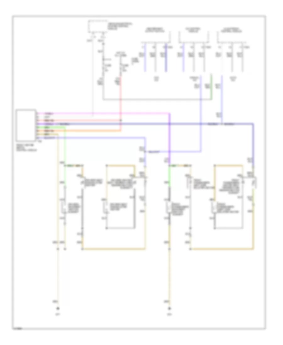 https://portal-diagnostov.com/license.html
Automotive Electricians Portal FZCO
Automotive Electricians Portal FZCO
https://portal-diagnostov.com/license.html
https://portal-diagnostov.com/license.html
Automotive Electricians Portal FZCO
Automotive Electricians Portal FZCOList of elements for Heated Seats Wiring Diagram, Late Production for Volkswagen GTI 2006:
- 37a
- A/c control module
- Auto a/c
- Climatronic control module
- Driver's backrest heating element
- Driver's heated seat temperature sensor/heating element
- Driver's seat side bolster heater
- Front heated seats control module
- Front passenger's backrest heating element
- Front passenger's heated seat temperature sensor/heating element
- Front passenger's seat side bolster heater
- Fuse 30a
- Fuse 5a
- Fuse panel c
- G77
- G78
- Heater/heat output switch
- Hot at all times
- Manual a/c
- Nca
- T20c
- T8z
- Vehicle electrical system control module
- W/o a/c
Power Seats Wiring Diagram for Volkswagen GTI 2006
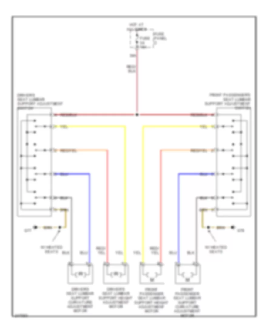 https://portal-diagnostov.com/license.html
Automotive Electricians Portal FZCO
Automotive Electricians Portal FZCO
https://portal-diagnostov.com/license.html
https://portal-diagnostov.com/license.html
Automotive Electricians Portal FZCO
Automotive Electricians Portal FZCOList of elements for Power Seats Wiring Diagram for Volkswagen GTI 2006:
- 34a
- Driver's seat lumbar support adjustment switch
- Driver's seat lumbar support curvature adjustment motor
- Driver's seat lumbar support height adjustment motor
- Front passenger seat lumbar support curvature adjustment motor
- Front passenger seat lumbar support height adjustment motor
- Front passenger's seat lumbar support adjustment switch
- Fuse 15a
- Fuse panel c
- G77
- G78
- Hot at all times
- W/ heated seats
POWER TOP/SUNROOF
Sunroof Wiring Diagram, Early Production for Volkswagen GTI 2006
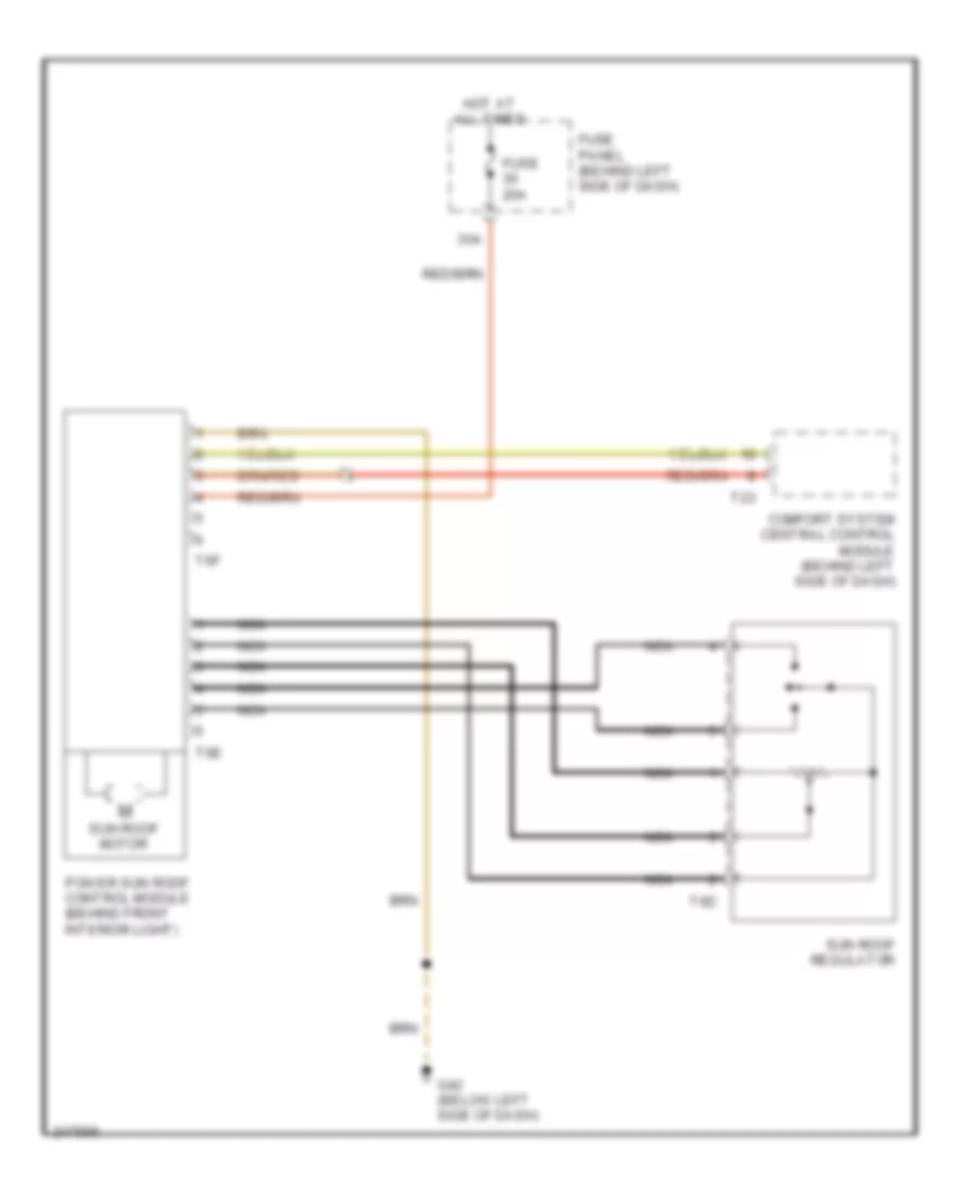 https://portal-diagnostov.com/license.html
Automotive Electricians Portal FZCO
Automotive Electricians Portal FZCO
https://portal-diagnostov.com/license.html
https://portal-diagnostov.com/license.html
Automotive Electricians Portal FZCO
Automotive Electricians Portal FZCOList of elements for Sunroof Wiring Diagram, Early Production for Volkswagen GTI 2006:
- 30a
- Comfort system central control module (behind left side of dash)
- Fuse 20a
- Fuse panel (behind left side of dash)
- G42 (below left side of dash)
- Hot at all times
- Nca
- Power sun roof control module (behind front interior light)
- Sun roof motor
- Sun roof regulator
- T23
- T6d
- T6e
- T6f
Sunroof Wiring Diagram, Late Production for Volkswagen GTI 2006
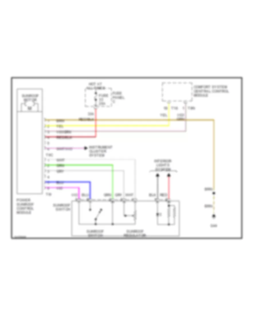 https://portal-diagnostov.com/license.html
Automotive Electricians Portal FZCO
Automotive Electricians Portal FZCO
https://portal-diagnostov.com/license.html
https://portal-diagnostov.com/license.html
Automotive Electricians Portal FZCO
Automotive Electricians Portal FZCOList of elements for Sunroof Wiring Diagram, Late Production for Volkswagen GTI 2006:
- 33a
- Comfort system central control module
- Fuse 25a
- Fuse panel c
- G44
- Hot at all times
- Instrument cluster system
- Interior lights system
- Power sunroof control module
- Red
- Sunroof motor
- Sunroof regulator
- Sunroof switch
- T18
- T6c
- T6i
- T8n
POWER WINDOWS
Power Windows Wiring Diagram, Early Production for Volkswagen GTI 2006
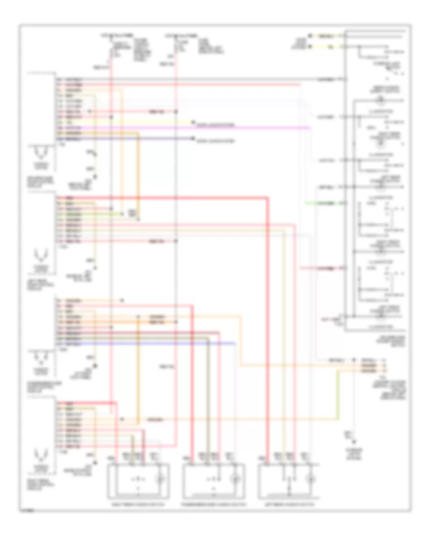 https://portal-diagnostov.com/license.html
Automotive Electricians Portal FZCO
Automotive Electricians Portal FZCO
https://portal-diagnostov.com/license.html
https://portal-diagnostov.com/license.html
Automotive Electricians Portal FZCO
Automotive Electricians Portal FZCOList of elements for Power Windows Wiring Diagram, Early Production for Volkswagen GTI 2006:
- (not used)
- 38a
- Circuit breaker 30a
- Comfort system central control module (behind left side of dash)
- Door locks system
- Driver's side door control module
- Driver's side power window switch
- Fuse 15a
- Fuse panel (behind left side of dash)
- G43 (at right kick panel)
- G44 (behind left kick panel)
- G77 (base of left "b" pillar)
- G78 (base of right "b" pillar)
- Hot at all times
- Illumination
- Interior lights system
- Interior lock switch
- Left front window switch
- Left rear door control module
- Left rear window switch
- Passenger's side door control module
- Passenger's side window switch
- Power window circuit breaker (in relay panel)
- Rear window safety switch
- Red
- Right front window switch
- Right rear door control module
- Right rear window switch
- T16a
- T18a
- T18b
- T23
- T29
- T29a
- Window motor
Power Windows Wiring Diagram, Late Production for Volkswagen GTI 2006
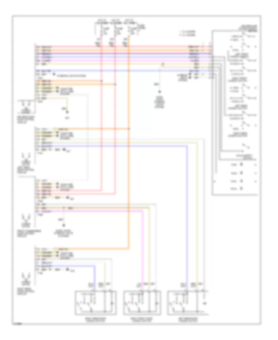 https://portal-diagnostov.com/license.html
Automotive Electricians Portal FZCO
Automotive Electricians Portal FZCO
https://portal-diagnostov.com/license.html
https://portal-diagnostov.com/license.html
Automotive Electricians Portal FZCO
Automotive Electricians Portal FZCOList of elements for Power Windows Wiring Diagram, Late Production for Volkswagen GTI 2006:
- 12a
- 23a
- 26a
- Child safety switch
- Computer data lines system
- Door locks/ interior lights system
- Door locks/ interior lights systems
- Driver's door door control module
- Driver's side power window switch
- Front passenger's door control module
- Fuse 10a
- Fuse 30a
- Fuse panel c
- G44
- G47
- G77
- G78
- Hot at all times
- Interior lights system
- Left front window switch
- Left rear door control module
- Left rear door window switch
- Left rear window switch
- M window motor
- Right front door window switch
- Right front window switch
- Right rear door control module
- Right rear door window switch
- Right rear window switch
- T18c
- T18d
- T20a
- T20b
- T32a
- T32b
- W/ 2 doors
- W/ 4 doors
- Window motor
RADIO
Base Radio Wiring Diagram for Volkswagen GTI 2006
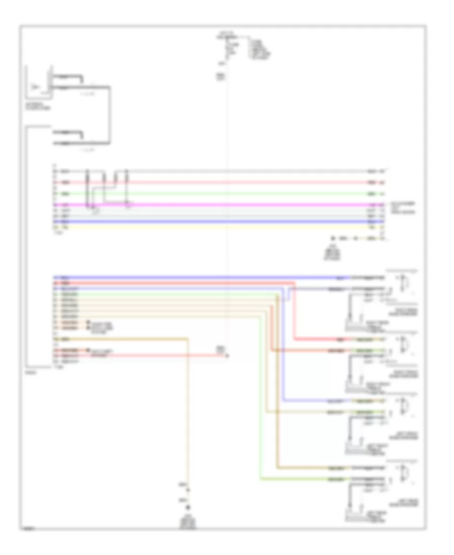 https://portal-diagnostov.com/license.html
Automotive Electricians Portal FZCO
Automotive Electricians Portal FZCO
https://portal-diagnostov.com/license.html
https://portal-diagnostov.com/license.html
Automotive Electricians Portal FZCO
Automotive Electricians Portal FZCOList of elements for Base Radio Wiring Diagram for Volkswagen GTI 2006:
- 42a
- Antenna (w/amplifier)
- Anti-theft system
- Cd changer unit (provisions)
- Computer data lines system
- Fuse 25a
- Fuse panel (behind left side of dash)
- G45 (behind center of dash)
- Hot at all times
- Left front bass speaker
- Left front treble tweeter
- Left rear bass speaker
- Left rear treble tweeter
- Nca
- Radio
- Red
- Right front bass speaker
- Right front treble tweeter
- Right rear bass speaker
- Right rear treble tweeter
- T12y
- T16d
Premium Sound Radio Wiring Diagram, Early Production for Volkswagen GTI 2006
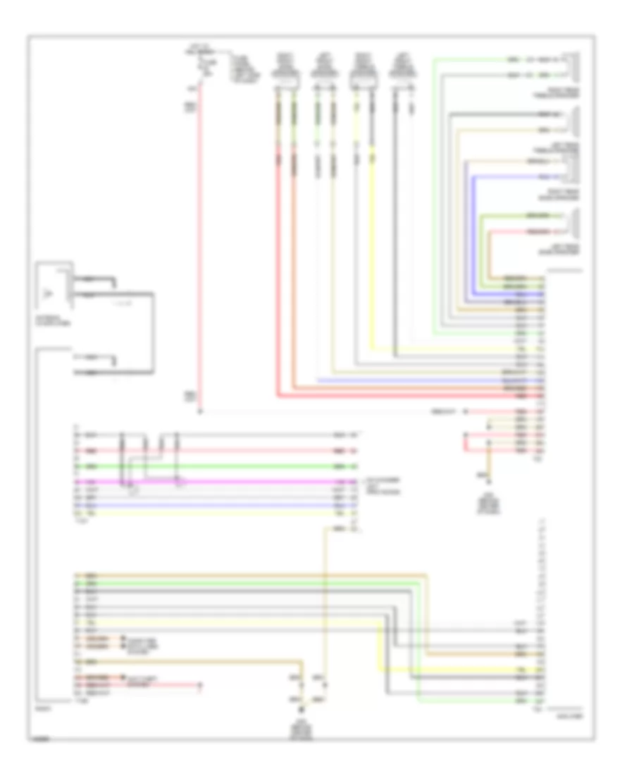 https://portal-diagnostov.com/license.html
Automotive Electricians Portal FZCO
Automotive Electricians Portal FZCO
https://portal-diagnostov.com/license.html
https://portal-diagnostov.com/license.html
Automotive Electricians Portal FZCO
Automotive Electricians Portal FZCOList of elements for Premium Sound Radio Wiring Diagram, Early Production for Volkswagen GTI 2006:
- 42a
- Amplifier
- Antenna (w/amplifier)
- Anti-theft system
- Cd changer unit (provisions)
- Computer data lines system
- Fuse 25a
- Fuse panel (behind left side of dash)
- G45 (behind center of dash)
- Hot at all times
- Left front bass speaker
- Left front treble speaker
- Left rear bass speaker
- Left rear treble speaker
- Nca
- Radio
- Red
- Right front bass speaker
- Right front treble speaker
- Right rear bass speaker
- Right rear treble speaker
- T12y
- T16d
- T23
- T24
Premium Sound Radio Wiring Diagram, Late Production (1 of 2) for Volkswagen GTI 2006
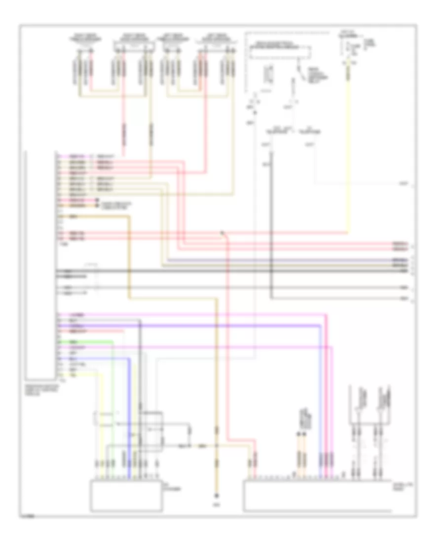 https://portal-diagnostov.com/license.html
Automotive Electricians Portal FZCO
Automotive Electricians Portal FZCO
https://portal-diagnostov.com/license.html
https://portal-diagnostov.com/license.html
Automotive Electricians Portal FZCO
Automotive Electricians Portal FZCOList of elements for Premium Sound Radio Wiring Diagram, Late Production (1 of 2) for Volkswagen GTI 2006:
- Cd changer
- Computer data lines system
- Fuse 15a
- Fuse panel b
- G45
- Hot at all times
- Left rear bass speaker
- Left rear treble speaker
- Nca
- Radio/navigation display control module
- Rear window defogger relay
- Right rear bass speaker
- Right rear treble speaker
- Satellite
- Satellite antenna
- Satellite radio
- T12
- T16b
- T8a
- T8b
- Tuner antenna
- Vehicle electrical system control module
- W/ telephone
- W/o telephone
Premium Sound Radio Wiring Diagram, Late Production (2 of 2) for Volkswagen GTI 2006
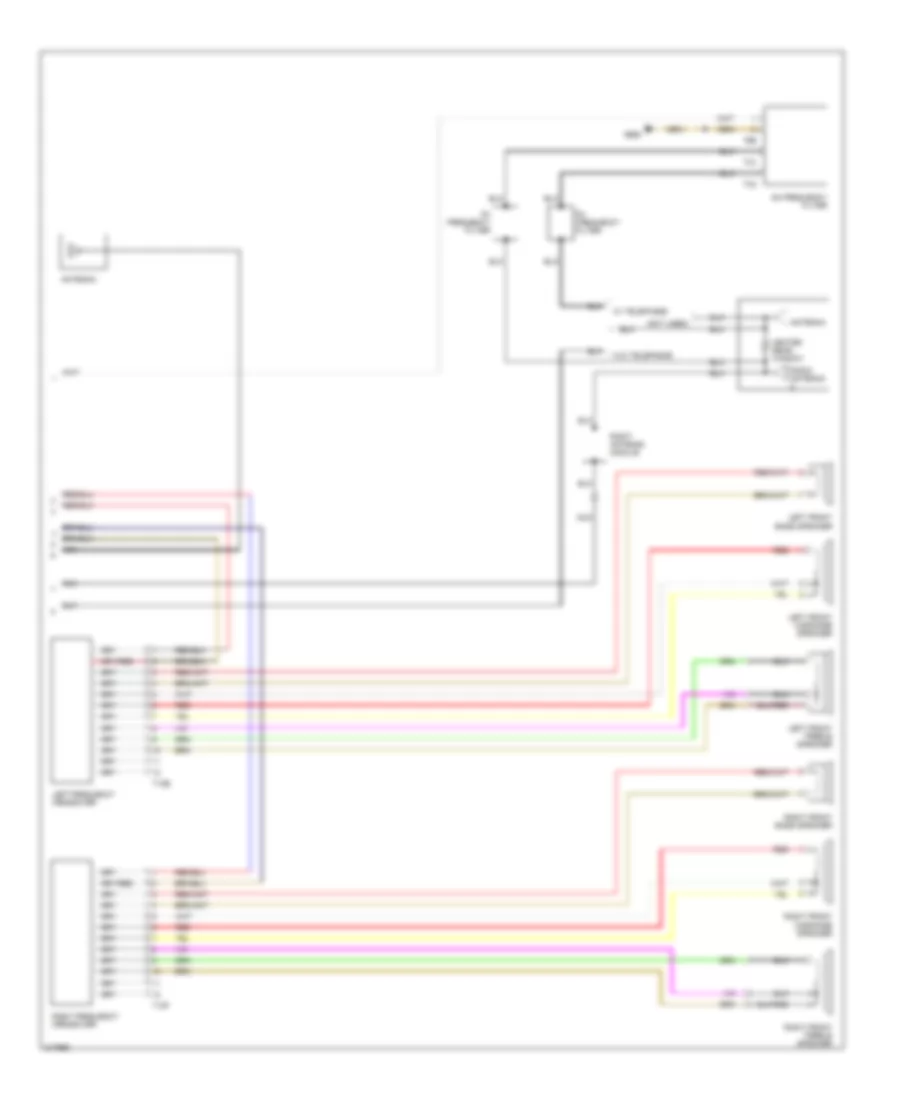 https://portal-diagnostov.com/license.html
Automotive Electricians Portal FZCO
Automotive Electricians Portal FZCO
https://portal-diagnostov.com/license.html
https://portal-diagnostov.com/license.html
Automotive Electricians Portal FZCO
Automotive Electricians Portal FZCOList of elements for Premium Sound Radio Wiring Diagram, Late Production (2 of 2) for Volkswagen GTI 2006:
- (not used)
- Am frequency filter
- Antenna
- Fm frequency filter
- G662
- Heated rear window
- Left frequency crossover
- Left front bass speaker
- Left front midrange speaker
- Left front treble speaker
- Nca
- Radio antenna
- Red
- Right antenna module
- Right frequency crossover
- Right front bass speaker
- Right front midrange speaker
- Right front treble speaker
- T12e
- T12f
- T1c
- T1d
- T2b
- W/ telephone
- W/o telephone
Radio/Navigation Wiring Diagram (1 of 2) for Volkswagen GTI 2006
 https://portal-diagnostov.com/license.html
Automotive Electricians Portal FZCO
Automotive Electricians Portal FZCO
https://portal-diagnostov.com/license.html
https://portal-diagnostov.com/license.html
Automotive Electricians Portal FZCO
Automotive Electricians Portal FZCOList of elements for Radio/Navigation Wiring Diagram (1 of 2) for Volkswagen GTI 2006:
- Cd changer
- Computer data lines system
- Fuse 15a
- Fuse panel b
- G45
- Hot at all times
- Left rear bass speaker
- Left rear treble speaker
- Nca
- Radio/navigation display control module
- Rear window defogger relay
- Right rear bass speaker
- Right rear treble speaker
- Satellite
- Satellite antenna
- Satellite radio
- T12
- T16b
- T8a
- T8b
- Tuner antenna
- Vehicle electrical system control module
- W/ telephone
- W/o telephone
Radio/Navigation Wiring Diagram (2 of 2) for Volkswagen GTI 2006
 https://portal-diagnostov.com/license.html
Automotive Electricians Portal FZCO
Automotive Electricians Portal FZCO
https://portal-diagnostov.com/license.html
https://portal-diagnostov.com/license.html
Automotive Electricians Portal FZCO
Automotive Electricians Portal FZCOList of elements for Radio/Navigation Wiring Diagram (2 of 2) for Volkswagen GTI 2006:
- (not used)
- Am frequency filter
- Antenna
- Fm frequency filter
- G662
- Heated rear window
- Left frequency crossover
- Left front bass speaker
- Left front midrange speaker
- Left front treble speaker
- Navigation system antenna
- Nca
- Radio antenna
- Red
- Right antenna module
- Right frequency crossover
- Right front bass speaker
- Right front midrange speaker
- Right front treble speaker
- T12e
- T12f
- T1c
- T1d
- T2b
- W/ telephone
- W/o telephone
SHIFT INTERLOCK
1.8L TURBO
1.8L Turbo, Shift Interlock Wiring Diagram for Volkswagen GTI 2006
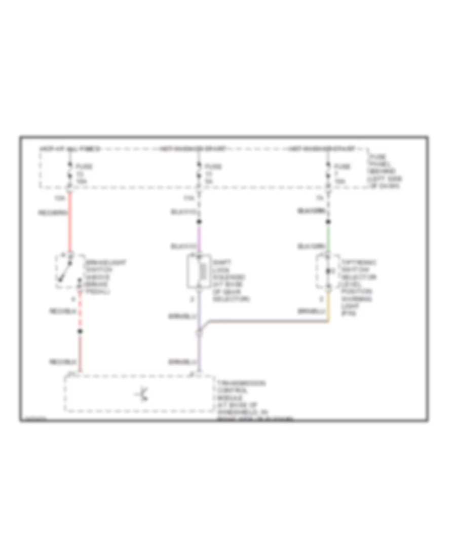 https://portal-diagnostov.com/license.html
Automotive Electricians Portal FZCO
Automotive Electricians Portal FZCO
https://portal-diagnostov.com/license.html
https://portal-diagnostov.com/license.html
Automotive Electricians Portal FZCO
Automotive Electricians Portal FZCOList of elements for 1.8L Turbo, Shift Interlock Wiring Diagram for Volkswagen GTI 2006:
- 11a
- 13a
- Brakelight switch (above brake pedal)
- Fuse 10a
- Fuse 5a
- Fuse panel (behind left side of dash)
- Hot at all times
- Hot in on or start
- Shift lock solenoid (at base of gear selector)
- Tiptronic switch/ selector level position warning light (p/n)
- Transmission control module (at base of windshield, in right side of plenum)
2.0L
2.0L, Shift Interlock Wiring Diagram for Volkswagen GTI 2006
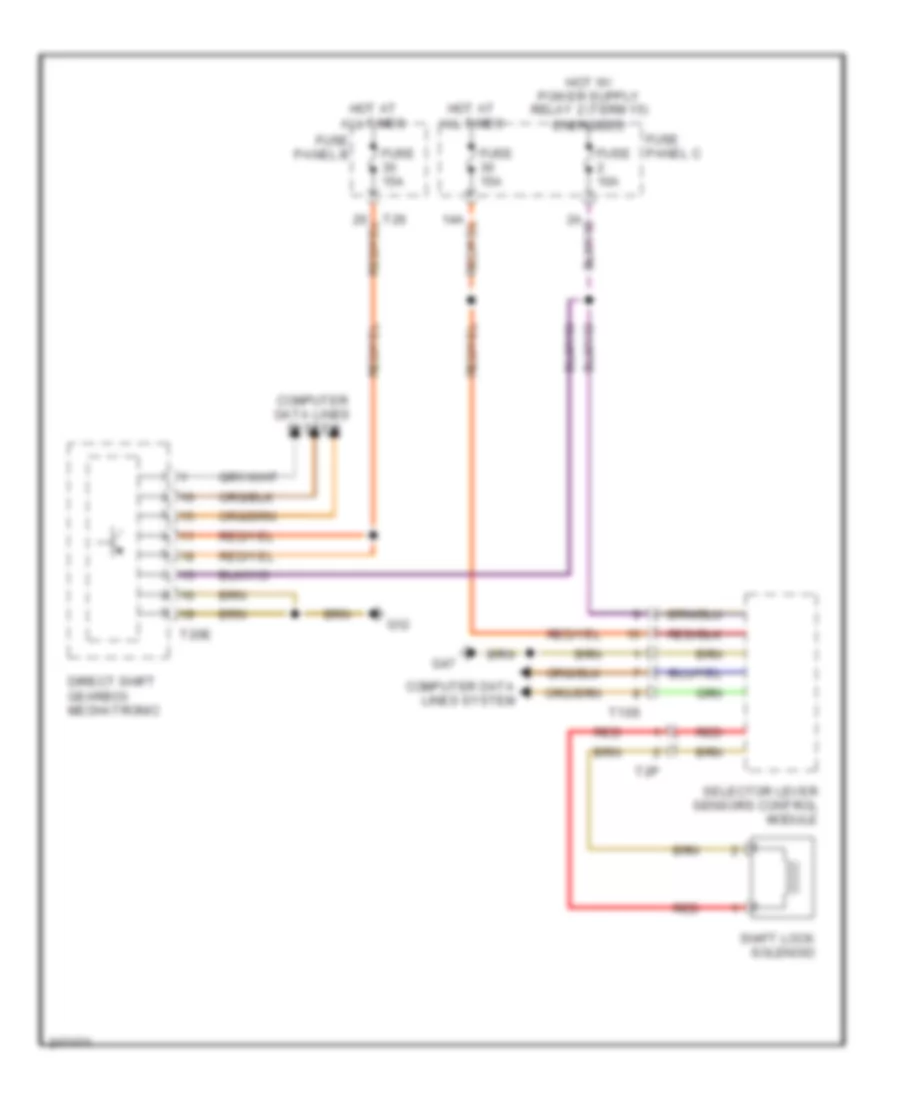 https://portal-diagnostov.com/license.html
Automotive Electricians Portal FZCO
Automotive Electricians Portal FZCO
https://portal-diagnostov.com/license.html
https://portal-diagnostov.com/license.html
Automotive Electricians Portal FZCO
Automotive Electricians Portal FZCOList of elements for 2.0L, Shift Interlock Wiring Diagram for Volkswagen GTI 2006:
- Computer data lines system
- Direct shift gearbox mechatronic
- Fuse 10a
- Fuse 15a
- Fuse panel b
- Fuse panel c
- G12
- G47
- Hot at all times
- Red
- Selector lever sensors control module
- Shift lock solenoid
- T10s
- T20e
- T26
- T2p
STARTING/CHARGING
1.8L TURBO
1.8L Turbo, Charging Wiring Diagram for Volkswagen GTI 2006
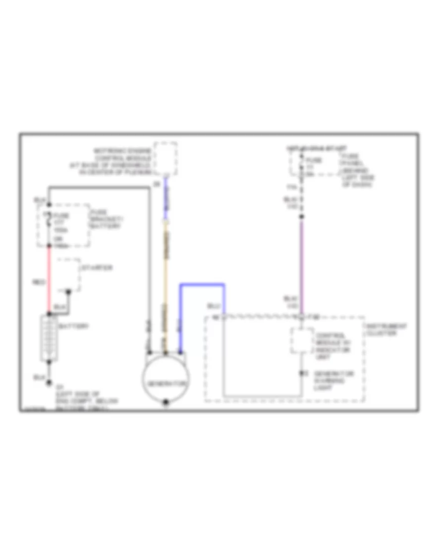 https://portal-diagnostov.com/license.html
Automotive Electricians Portal FZCO
Automotive Electricians Portal FZCO
https://portal-diagnostov.com/license.html
https://portal-diagnostov.com/license.html
Automotive Electricians Portal FZCO
Automotive Electricians Portal FZCOList of elements for 1.8L Turbo, Charging Wiring Diagram for Volkswagen GTI 2006:
- 11a
- B1+
- Battery
- Control module w/ indicator unit
- Dfm
- Fuse 150a
- Fuse 5a
- Fuse bracket/ battery
- Fuse panel (behind left side of dash)
- G1 (left side of eng compt, below battery tray)
- Generator
- Generator warning light
- Hot in on & start
- Instrument cluster
- Motronic engine control module (at base of windshield, in center of plenum)
- Or 110a
- Red
- Starter
- T32
1.8L Turbo, Starting Wiring Diagram, A/T for Volkswagen GTI 2006
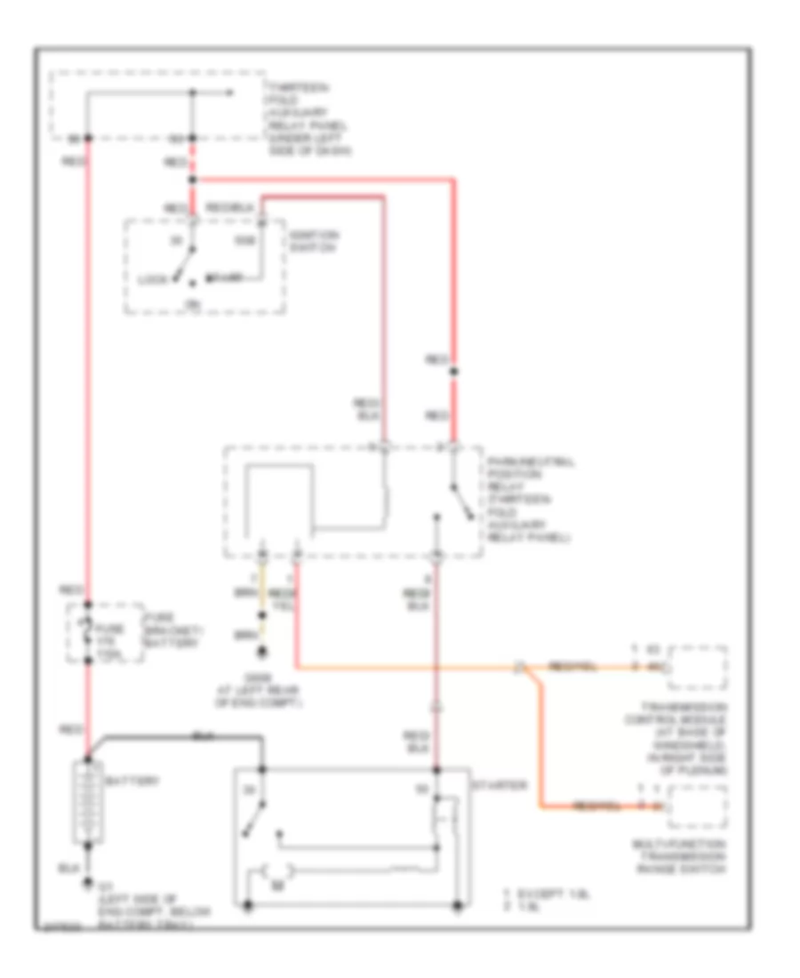 https://portal-diagnostov.com/license.html
Automotive Electricians Portal FZCO
Automotive Electricians Portal FZCO
https://portal-diagnostov.com/license.html
https://portal-diagnostov.com/license.html
Automotive Electricians Portal FZCO
Automotive Electricians Portal FZCOList of elements for 1.8L Turbo, Starting Wiring Diagram, A/T for Volkswagen GTI 2006:
- 50b
- Battery
- Except 1.8l 1.8l
- Fuse 110a
- Fuse bracket/ battery
- G1 (left side of eng compt, below battery tray)
- G608 at left rear of eng compt)
- Ignition switch
- Lock
- Multi-function transmission range switch
- Park/neutral position relay (thirteen- fold auxiliary relay panel)
- Red
- Start
- Starter
- Thirteen- fold auxiliary relay panel (under left side of dash)
- Transmission control module (at base of windshield, in right side of plenum)
1.8L Turbo, Starting Wiring Diagram, M/T for Volkswagen GTI 2006
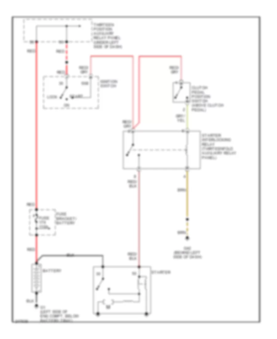 https://portal-diagnostov.com/license.html
Automotive Electricians Portal FZCO
Automotive Electricians Portal FZCO
https://portal-diagnostov.com/license.html
https://portal-diagnostov.com/license.html
Automotive Electricians Portal FZCO
Automotive Electricians Portal FZCOList of elements for 1.8L Turbo, Starting Wiring Diagram, M/T for Volkswagen GTI 2006:
- 50b
- Battery
- Clutch pedal position switch (above clutch pedal)
- Fuse 110a
- Fuse bracket/ battery
- G1 (left side of eng compt, below battery tray)
- G42 (behind left side of dash)
- Ignition switch
- Lock
- Red
- Start
- Starter
- Starter interlocking relay (thirteenfold auxiliary relay panel)
- Thirteen position auxiliary relay panel (under left side of dash)
2.0L
2.0L, Charging Wiring Diagram for Volkswagen GTI 2006
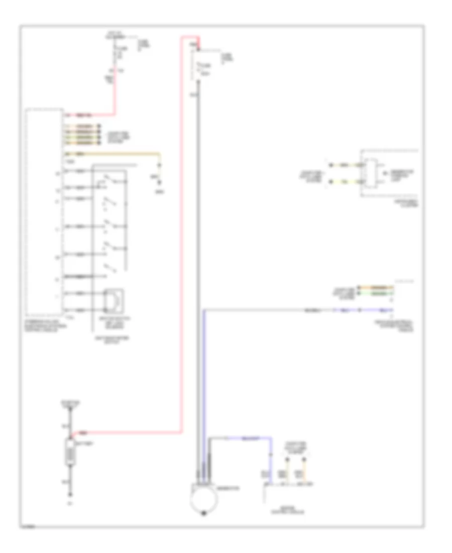 https://portal-diagnostov.com/license.html
Automotive Electricians Portal FZCO
Automotive Electricians Portal FZCO
https://portal-diagnostov.com/license.html
https://portal-diagnostov.com/license.html
Automotive Electricians Portal FZCO
Automotive Electricians Portal FZCOList of elements for 2.0L, Charging Wiring Diagram for Volkswagen GTI 2006:
- Battery
- Computer data lines system
- Engine control module
- Fuse 200a
- Fuse 5a
- Fuse panel a
- Fuse panel b
- G605
- Generator
- Generator warning lamp
- Hot at all times
- Ignition switch key lock solenoid
- Ignition/starter switch
- Instrument cluster
- Nca
- Red
- Starting circuit
- Steering column electronic systems control module
- T12j
- T20d
- T40
- T94
- Vehicle electrical system control module
2.0L, Starting Wiring Diagram for Volkswagen GTI 2006
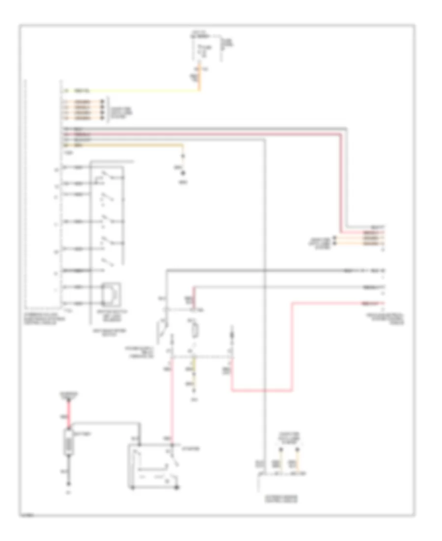 https://portal-diagnostov.com/license.html
Automotive Electricians Portal FZCO
Automotive Electricians Portal FZCO
https://portal-diagnostov.com/license.html
https://portal-diagnostov.com/license.html
Automotive Electricians Portal FZCO
Automotive Electricians Portal FZCOList of elements for 2.0L, Starting Wiring Diagram for Volkswagen GTI 2006:
- Battery
- Charging circuit
- Computer data lines system
- Fuse 5a
- Fuse panel b
- G44
- G605
- Hot at all times
- Ignition switch key lock solenoid
- Ignition/starter switch
- Motronic engine control module
- Nca
- Red
- Starter
- Steering column electronic systems control module
- T12j
- T20d
- T40
- T6d
- T94
- Vehicle electrical system control module
SUPPLEMENTAL RESTRAINTS
Supplemental Restraints Wiring Diagram, Early Production (1 of 2) for Volkswagen GTI 2006
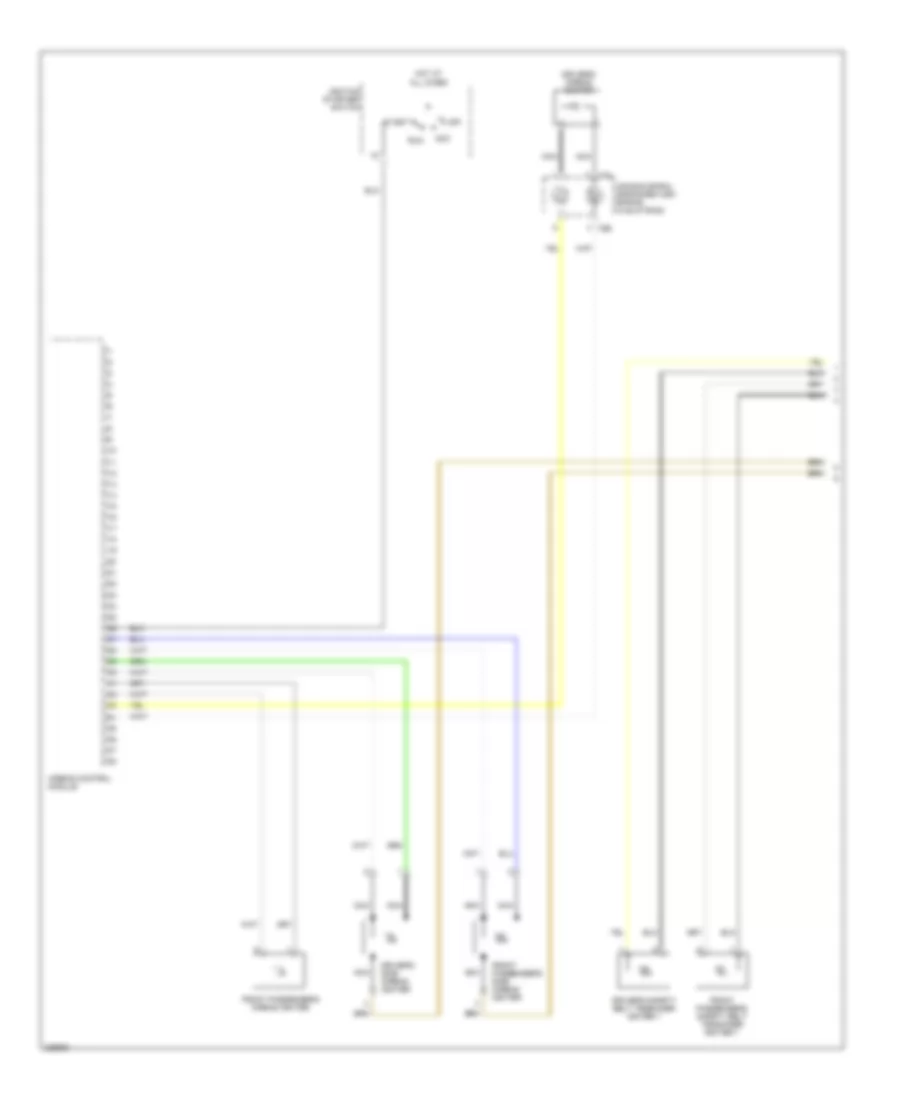 https://portal-diagnostov.com/license.html
Automotive Electricians Portal FZCO
Automotive Electricians Portal FZCO
https://portal-diagnostov.com/license.html
https://portal-diagnostov.com/license.html
Automotive Electricians Portal FZCO
Automotive Electricians Portal FZCOList of elements for Supplemental Restraints Wiring Diagram, Early Production (1 of 2) for Volkswagen GTI 2006:
- Acc
- Air bag spiral spring/return spring (w/slip ring)
- Airbag control module
- Driver's airbag igniter
- Driver's safety belt tensioner igniter 1
- Driver's side airbag igniter
- Front passenger's airbag igniter
- Front passenger's safety belt tensioner igniter 1
- Front passenger's side airbag igniter
- Hot at all times
- Ignition starter/ switch
- Nca
- Off
- Run
- Start
- T5b
- T5j
Supplemental Restraints Wiring Diagram, Early Production (2 of 2) for Volkswagen GTI 2006
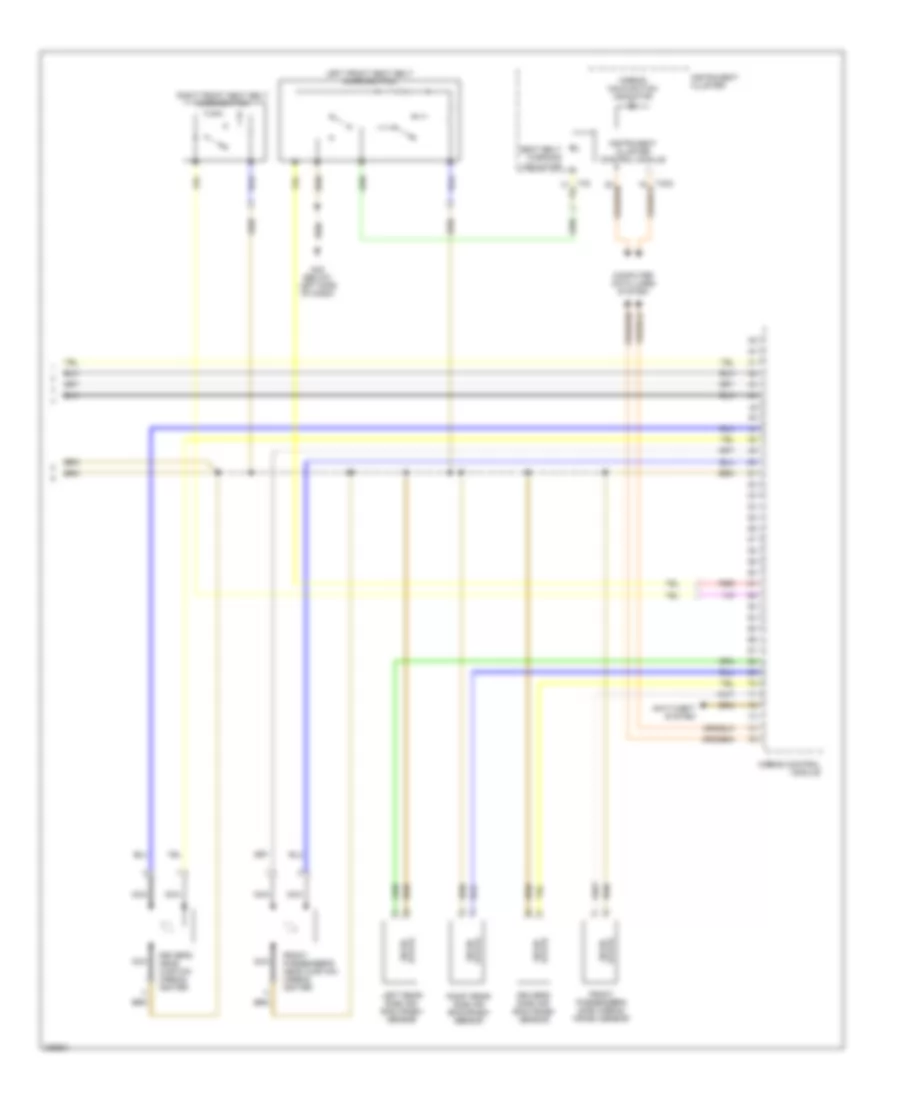 https://portal-diagnostov.com/license.html
Automotive Electricians Portal FZCO
Automotive Electricians Portal FZCO
https://portal-diagnostov.com/license.html
https://portal-diagnostov.com/license.html
Automotive Electricians Portal FZCO
Automotive Electricians Portal FZCOList of elements for Supplemental Restraints Wiring Diagram, Early Production (2 of 2) for Volkswagen GTI 2006:
- Airbag control module
- Airbag malfunction indicator
- Anti-theft system
- Computer data lines system
- Driver's head curtain airbag igniter
- Driver's side air- bag crash sensor
- Front passenger's head curtain airbag igniter
- Front passenger's side airbag crash sensor
- G42 (below left side of dash)
- Instrument cluster
- Instrument cluster control module
- Left front seat belt micro-switch
- Left rear side air- bag crash sensor
- Nca
- Red
- Right front seat belt micro-switch
- Right rear side air bag crash sensor
- Seat belt warning indicator
- State solid
Supplemental Restraints Wiring Diagram, Late Production (1 of 3) for Volkswagen GTI 2006
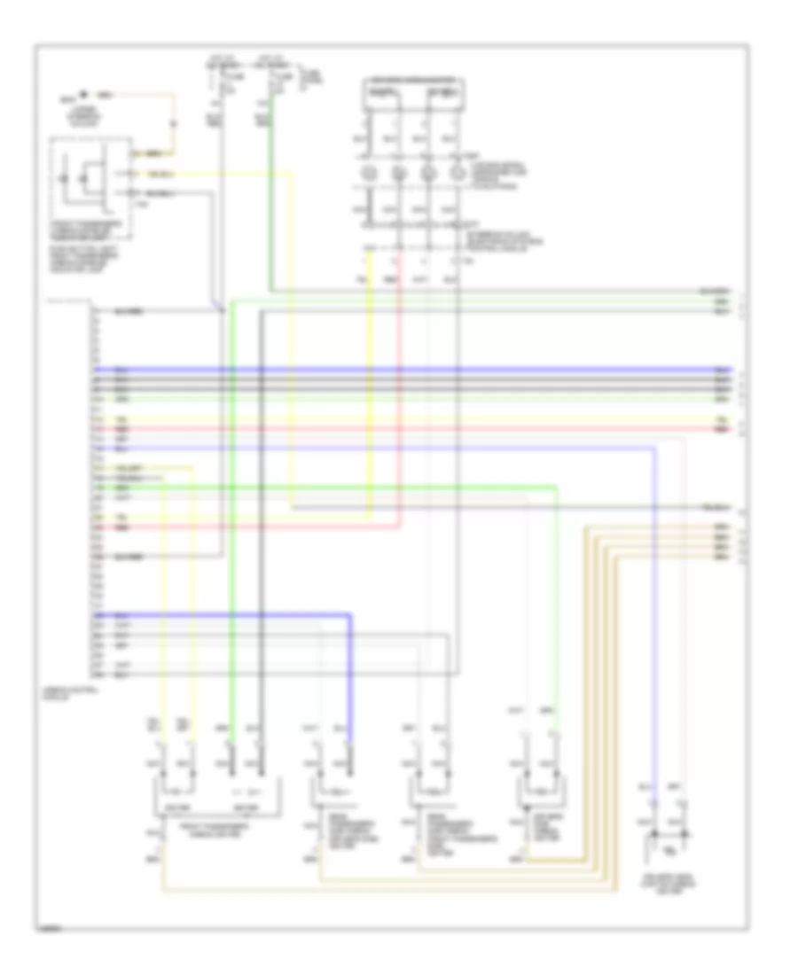 https://portal-diagnostov.com/license.html
Automotive Electricians Portal FZCO
Automotive Electricians Portal FZCO
https://portal-diagnostov.com/license.html
https://portal-diagnostov.com/license.html
Automotive Electricians Portal FZCO
Automotive Electricians Portal FZCOList of elements for Supplemental Restraints Wiring Diagram, Late Production (1 of 3) for Volkswagen GTI 2006:
- (upper steering column)
- 10a
- Air bag spiral spring/return spring (w/slip ring)
- Airbag control module
- Driver's airbag igniter
- Driver's head curtain airbag igniter
- Driver's side airbag igniter
- Front passenger's airbag disabled indicator lamp
- Front passenger's airbag igniter
- Fuse 5a
- Fuse panel c
- G605
- Hot at all times
- Igniter
- Igniter 1
- Igniter 2
- Nca
- Push button light/ front passenger's airbag disabled indicator lamp
- Rear passenger's side airbag (driver's side) igniter
- Rear passenger's side airbag (front passenger's side) igniter
- Red
- Steering column electronic systems control module
- T10x
- T12k
- T4g
- T4k
Supplemental Restraints Wiring Diagram, Late Production (2 of 3) for Volkswagen GTI 2006
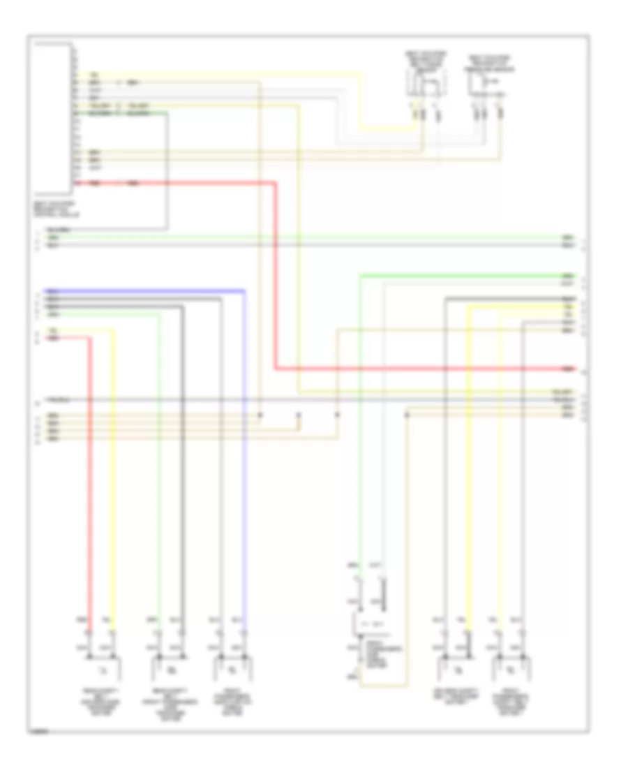 https://portal-diagnostov.com/license.html
Automotive Electricians Portal FZCO
Automotive Electricians Portal FZCO
https://portal-diagnostov.com/license.html
https://portal-diagnostov.com/license.html
Automotive Electricians Portal FZCO
Automotive Electricians Portal FZCOList of elements for Supplemental Restraints Wiring Diagram, Late Production (2 of 3) for Volkswagen GTI 2006:
- Driver's safety belt tensioner igniter 1
- Front passenger's head curtain airbag igniter
- Front passenger's safety belt tensioner igniter 1
- Front passenger's side airbag igniter
- Nca
- Rear safety belt (driver's side) tensioner igniter
- Rear safety belt (front passenger's side) tensioner igniter
- Red
- Seat occupied recognition belt force sensor
- Seat occupied recognition control module
- Seat occupied recognition pressure sensor
Supplemental Restraints Wiring Diagram, Late Production (3 of 3) for Volkswagen GTI 2006
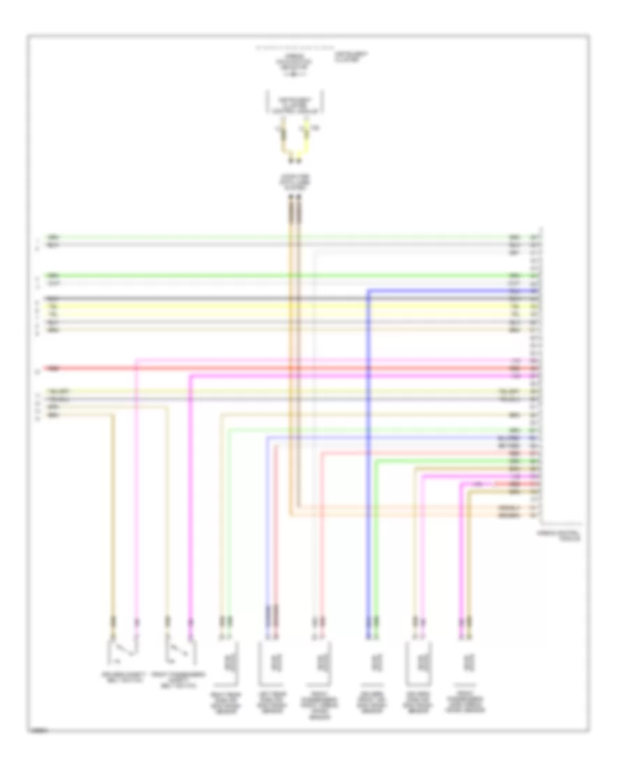 https://portal-diagnostov.com/license.html
Automotive Electricians Portal FZCO
Automotive Electricians Portal FZCO
https://portal-diagnostov.com/license.html
https://portal-diagnostov.com/license.html
Automotive Electricians Portal FZCO
Automotive Electricians Portal FZCOList of elements for Supplemental Restraints Wiring Diagram, Late Production (3 of 3) for Volkswagen GTI 2006:
- Airbag control module
- Airbag malfunction indicator
- Computer data lines system
- Driver's front air- bag crash sensor
- Driver's safety belt switch
- Driver's side air- bag crash sensor
- Front passenger's front airbag crash sensor
- Front passenger's safety belt switch
- Front passenger's side airbag crash sensor
- Instrument cluster
- Instrument cluster control module
- Left rear side air- bag crash sensor
- Red
- Right rear side air bag crash sensor
- State solid
TRANSMISSION
1.8L TURBO
1.8L Turbo, A/T Wiring Diagram, Early Production with 5 Speed A/T for Volkswagen GTI 2006
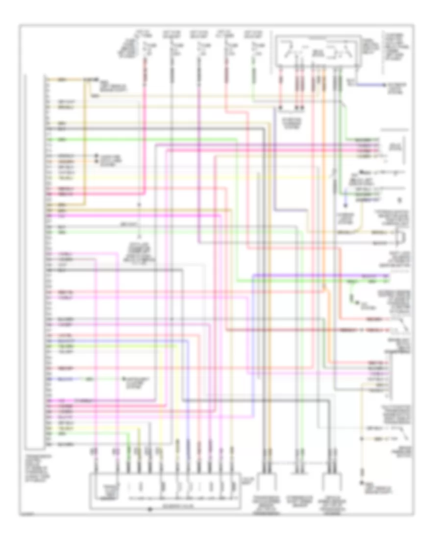 https://portal-diagnostov.com/license.html
Automotive Electricians Portal FZCO
Automotive Electricians Portal FZCO
https://portal-diagnostov.com/license.html
https://portal-diagnostov.com/license.html
Automotive Electricians Portal FZCO
Automotive Electricians Portal FZCOList of elements for 1.8L Turbo, A/T Wiring Diagram, Early Production with 5 Speed A/T for Volkswagen GTI 2006:
- (below left side of dash)
- 11a
- 13a
- 15a
- 31a
- A/c system
- Brake pressure switch
- Brakelight switch (above brake pedal)
- Computer data lines system
- Data link connector (under left side of dash, below steering column)
- Exterior lights system
- Fuse 10a
- Fuse 20a
- Fuse 5a
- Fuse panel (behind left side of dash)
- G42
- G608 (left rear of engine compt)
- Hot at all times
- Hot in on or start
- Instrument cluster system
- Interior lights system
- Intermediate shaft speed sensor
- Motronic engine control module (at base of windshield, in center of plenum)
- Multi-function transmission range switch (right side of transmission)
- Nca
- Park/ neutral position relay
- Red
- Shift lock solenoid (at base of gear selector)
- Solenoid valve
- Solid state
- Starting/ charging system
- Thirteen position auxiliary relay panel (under left side of dash)
- Tiptronic switch/ selector level position p/n warning light
- Trans fluid temp sensor
- Transmission control module (at base of windshield, in right side of plenum)
- Transmission vehicle speed sensor (on top of transmission)
- Valve body
- Vehicle speed sensor (on top of transmission housing)
2.0L
2.0L, A/T Wiring Diagram, Late Production with Direct Shift Automatic Transmission for Volkswagen GTI 2006
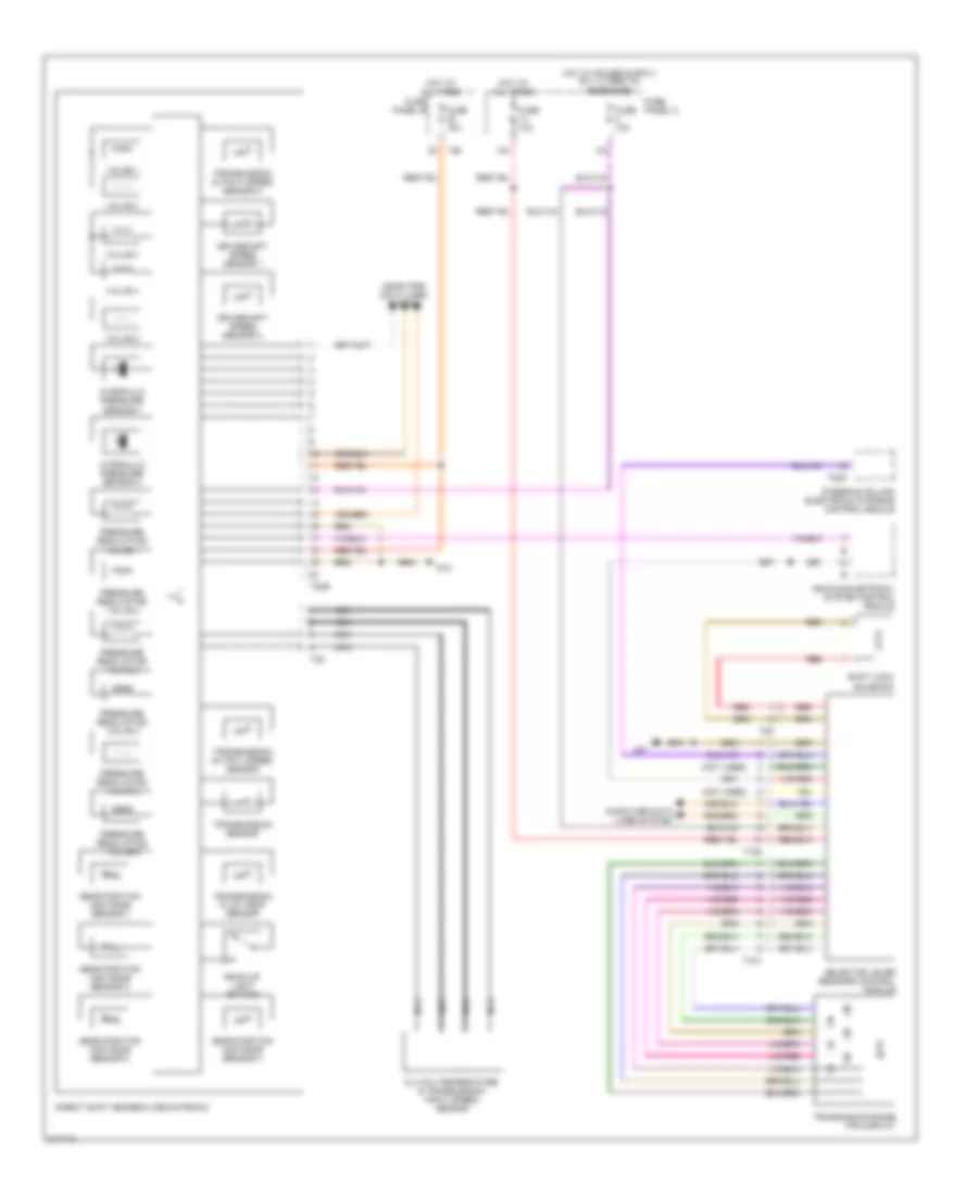 https://portal-diagnostov.com/license.html
Automotive Electricians Portal FZCO
Automotive Electricians Portal FZCO
https://portal-diagnostov.com/license.html
https://portal-diagnostov.com/license.html
Automotive Electricians Portal FZCO
Automotive Electricians Portal FZCOList of elements for 2.0L, A/T Wiring Diagram, Late Production with Direct Shift Automatic Transmission for Volkswagen GTI 2006:
- (not used)
- 14a
- Back-up light switch
- Clutch temperature & transmission input speed sensor
- Computer data lines system
- Direct shift gearbox mechatronic
- Driveshaft speed sensor 1
- Driveshaft speed sensor 2
- Fuse 10a
- Fuse 15a
- Fuse panel b
- Fuse panel c
- G12
- G47
- Gear position distance sensor 1
- Gear position distance sensor 2
- Gear position distance sensor 3
- Gear position distance sensor 4
- Hot at all times
- Hydraulic pressure sensor 1
- Hydraulic pressure sensor 2
- Nca
- Pressure regulating valve 1
- Pressure regulating valve 2
- Pressure regulating valve 3
- Pressure regulating valve 4
- Pressure regulating valve 5
- Pressure regulating valve 6
- Red
- Selector lever sensors control module
- Shift lock solenoid
- Steering column electronic systems control module
- T10s
- T10v
- T20d
- T20e
- T26
- T2p
- T4z
- Transmision range (tr) display
- Transmission fluid temp sensor
- Transmission output speed sensor
- Transmission output speed sensor 2
- Transmission sensor
- Valve 1
- Valve 2
- Valve 3
- Valve 4
- Valve 5
- Vehicle electrical system control module
TRUNK, TAILGATE, FUEL DOOR
Deck Lid Release Wiring Diagram, Early Production for Volkswagen GTI 2006
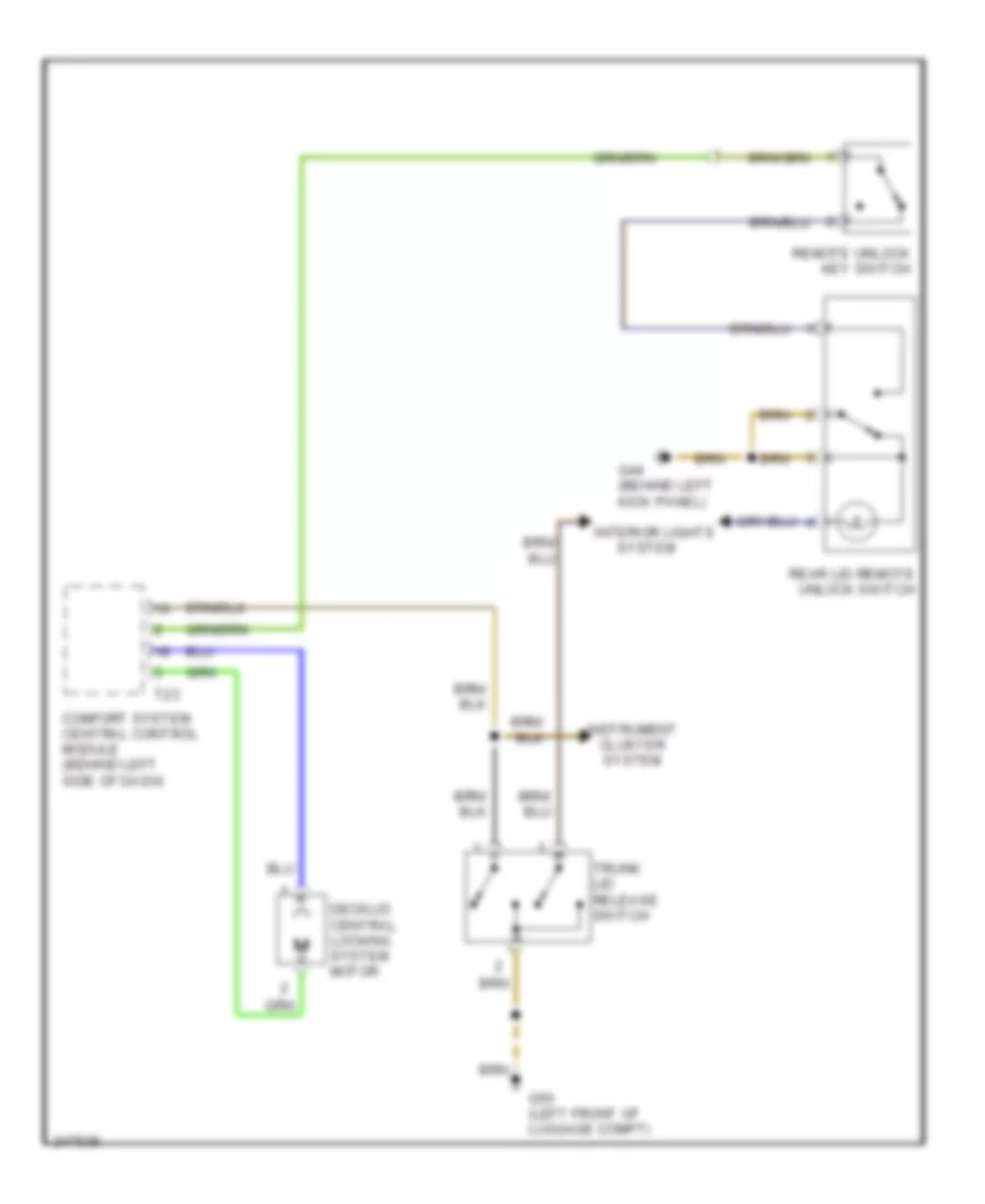 https://portal-diagnostov.com/license.html
Automotive Electricians Portal FZCO
Automotive Electricians Portal FZCO
https://portal-diagnostov.com/license.html
https://portal-diagnostov.com/license.html
Automotive Electricians Portal FZCO
Automotive Electricians Portal FZCOList of elements for Deck Lid Release Wiring Diagram, Early Production for Volkswagen GTI 2006:
- Comfort system central control module (behind left side of dash)
- Decklid central locking system motor
- G44 (behind left kick panel)
- G50 (left front of luggage compt)
- Instrument cluster system
- Interior lights
- Rear lid remote unlock switch
- Remote unlock key switch
- System
- T23
- Trunk lid release switch
Fuel Door Release Wiring Diagram, Early Production for Volkswagen GTI 2006
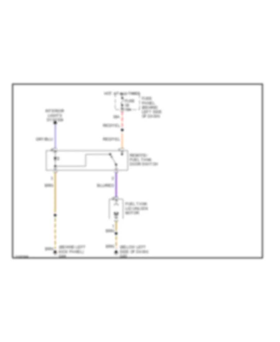 https://portal-diagnostov.com/license.html
Automotive Electricians Portal FZCO
Automotive Electricians Portal FZCO
https://portal-diagnostov.com/license.html
https://portal-diagnostov.com/license.html
Automotive Electricians Portal FZCO
Automotive Electricians Portal FZCOList of elements for Fuel Door Release Wiring Diagram, Early Production for Volkswagen GTI 2006:
- (behind left kick panel) g44
- (below left side of dash) g42
- 38a
- Fuel tank lid unlock motor
- Fuse 15a
- Fuse panel (behind left side of dash)
- Hot at all times
- Interior lights system
- Remote/ fuel tank door switch
Trunk & Fuel Door Release Wiring Diagram, Late Production for Volkswagen GTI 2006
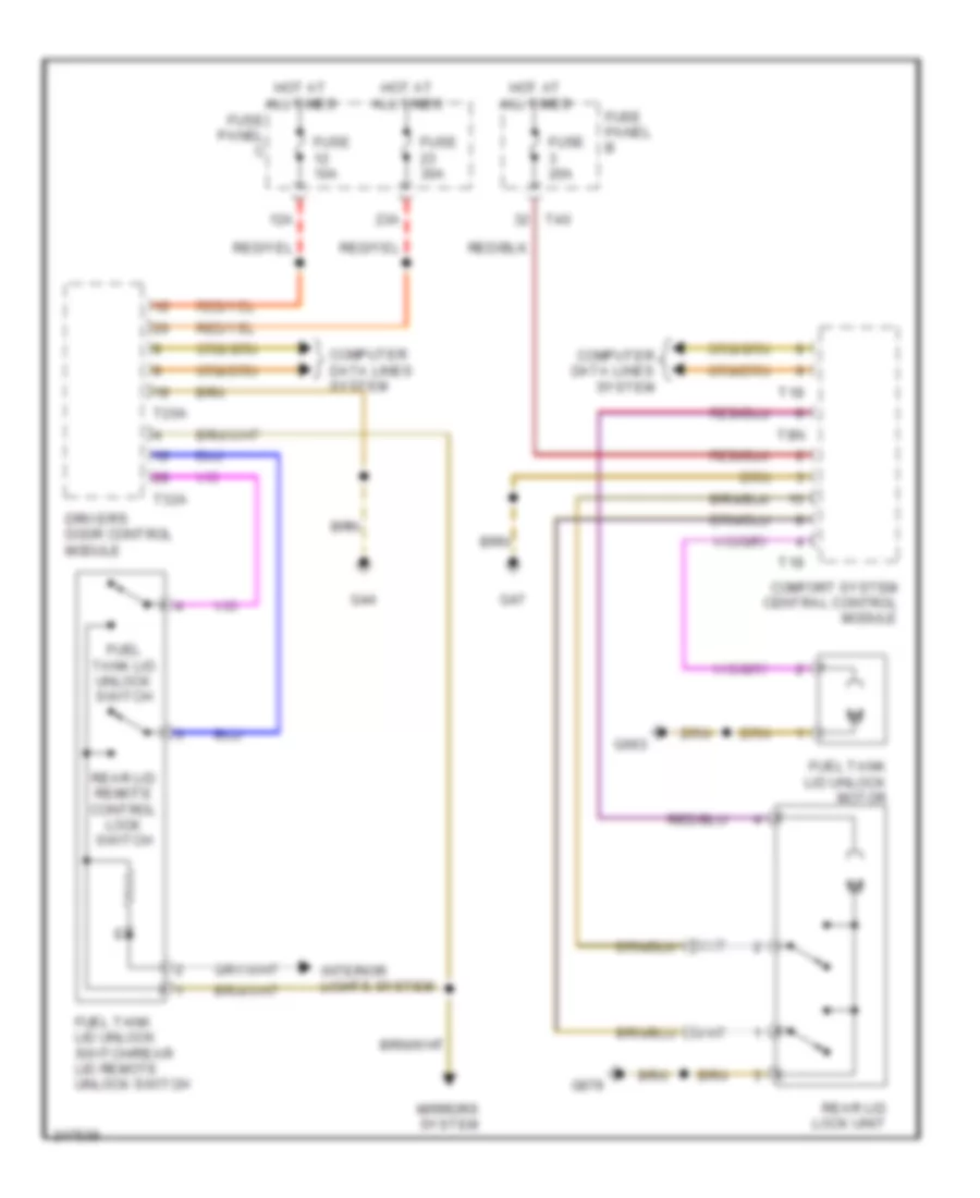 https://portal-diagnostov.com/license.html
Automotive Electricians Portal FZCO
Automotive Electricians Portal FZCO
https://portal-diagnostov.com/license.html
https://portal-diagnostov.com/license.html
Automotive Electricians Portal FZCO
Automotive Electricians Portal FZCOList of elements for Trunk & Fuel Door Release Wiring Diagram, Late Production for Volkswagen GTI 2006:
- 12a
- 23a
- Comfort system central control module
- Computer data lines system
- Driver's door control module
- Fuel tank lid unlock motor
- Fuel tank lid unlock switch
- Fuel tank lid unlock switch/rear lid remote unlock switch
- Fuse 10a
- Fuse 20a
- Fuse 30a
- Fuse panel b
- Fuse panel c
- G44
- G47
- G663
- G679
- Hot at all times
- Interior lights system
- Mirrors system
- Rear lid lock unit
- Rear lid remote control lock switch
- T18
- T20a
- T32a
- T40
- T8n
WARNING SYSTEMS
Warning Systems Wiring Diagram, Early Production for Volkswagen GTI 2006
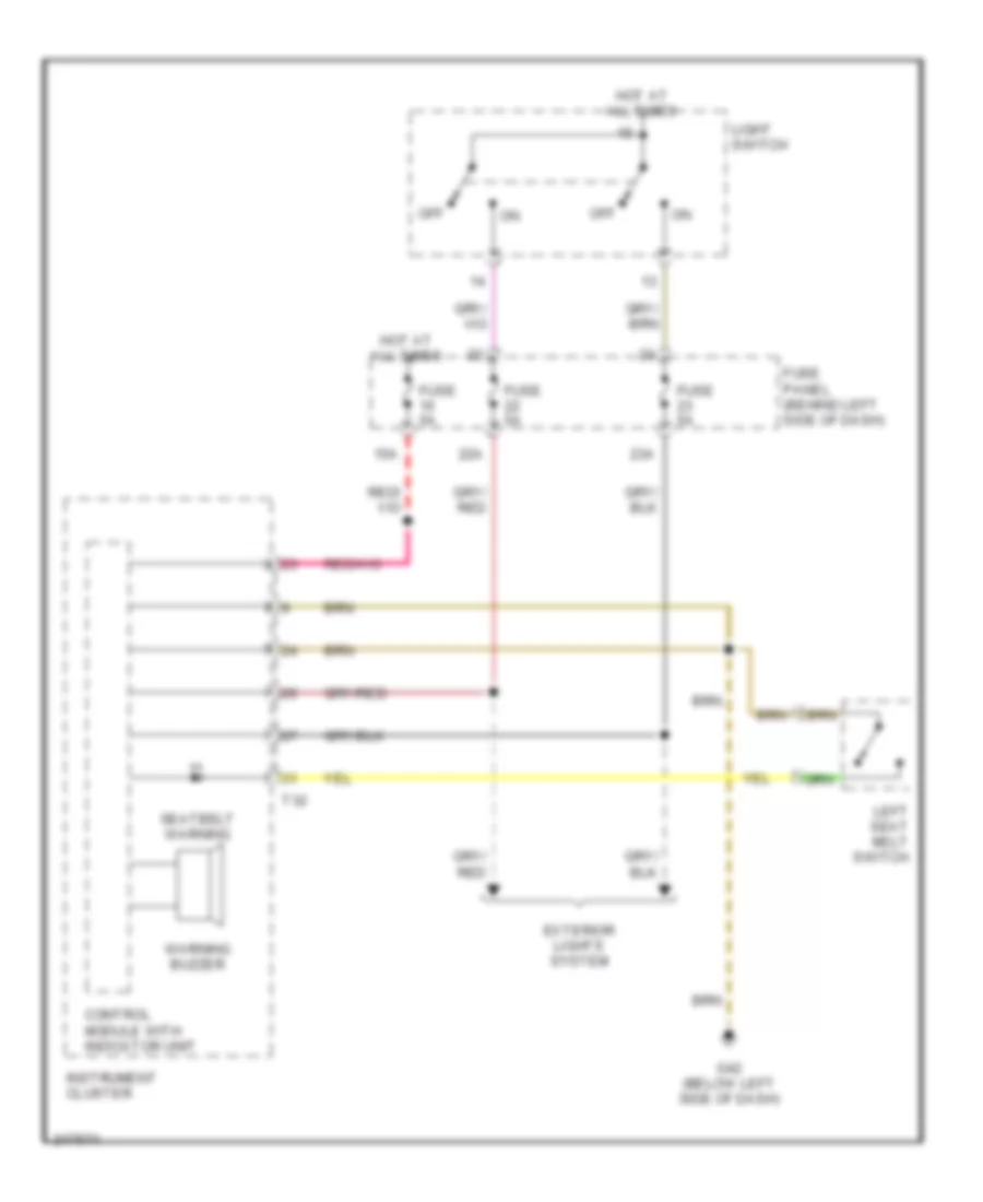 https://portal-diagnostov.com/license.html
Automotive Electricians Portal FZCO
Automotive Electricians Portal FZCO
https://portal-diagnostov.com/license.html
https://portal-diagnostov.com/license.html
Automotive Electricians Portal FZCO
Automotive Electricians Portal FZCOList of elements for Warning Systems Wiring Diagram, Early Production for Volkswagen GTI 2006:
- 15a
- 22a
- 23a
- Control module with indicator unit
- Exterior lights system
- Fuse 5a
- Fuse panel (behind left side of dash)
- G42 (below left side of dash)
- Hot at all times
- Instrument cluster
- Left seat belt switch
- Light switch
- Off
- Seatbelt warning
- T32
- Warning buzzer
Warning Systems Wiring Diagram, Late Production for Volkswagen GTI 2006
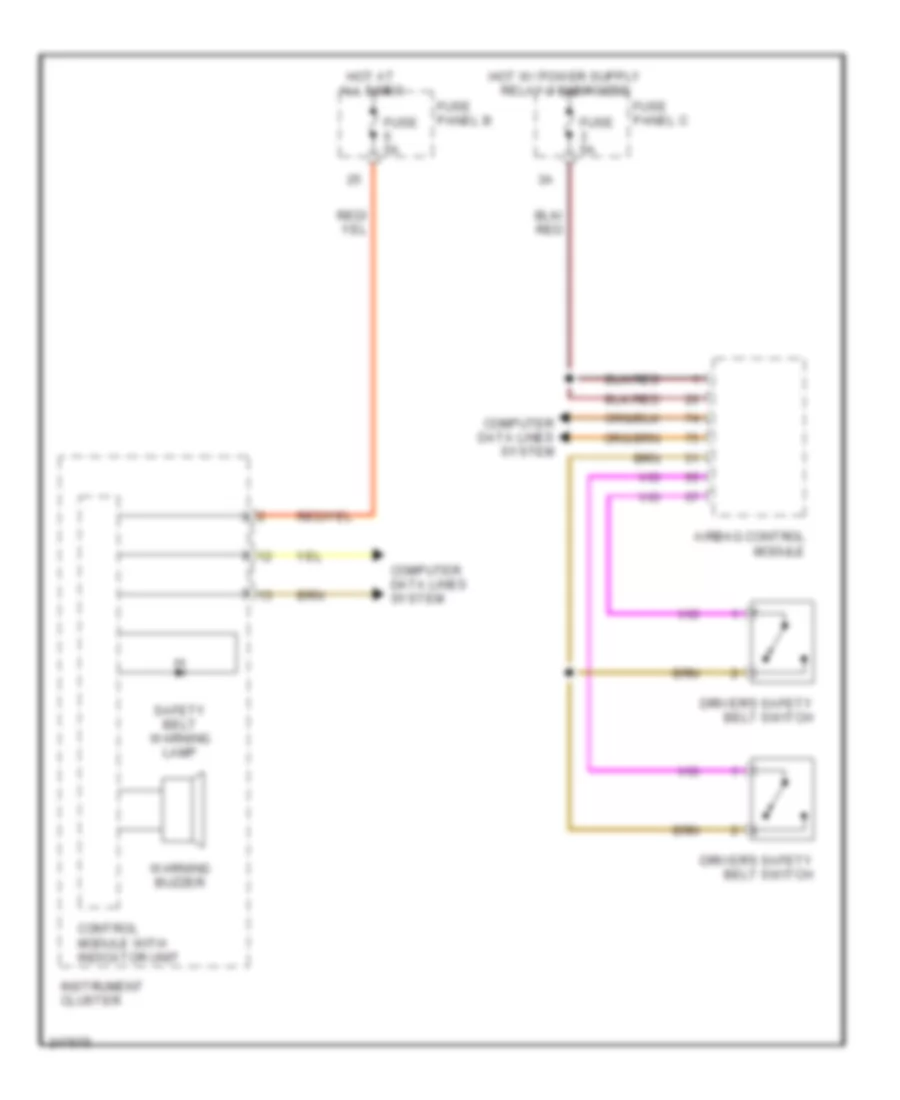 https://portal-diagnostov.com/license.html
Automotive Electricians Portal FZCO
Automotive Electricians Portal FZCO
https://portal-diagnostov.com/license.html
https://portal-diagnostov.com/license.html
Automotive Electricians Portal FZCO
Automotive Electricians Portal FZCOList of elements for Warning Systems Wiring Diagram, Late Production for Volkswagen GTI 2006:
- Airbag control module
- Computer data lines system
- Control module with indicator unit
- Driver's safety belt switch
- Fuse 5a
- Fuse panel b
- Fuse panel c
- Hot at all times
- Instrument cluster
- Safety belt warning lamp
- Warning buzzer
WIPER/WASHER
Wiper/Washer Wiring Diagram, Early Production for Volkswagen GTI 2006
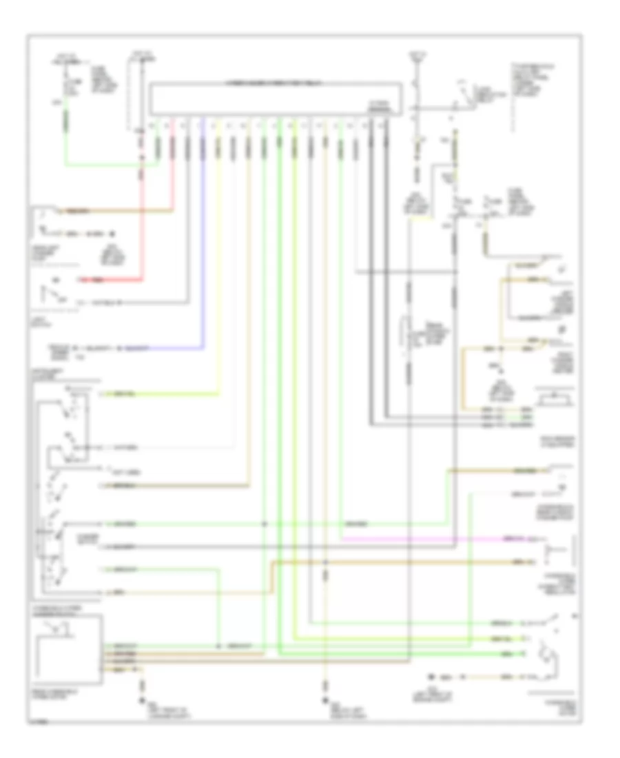 https://portal-diagnostov.com/license.html
Automotive Electricians Portal FZCO
Automotive Electricians Portal FZCO
https://portal-diagnostov.com/license.html
https://portal-diagnostov.com/license.html
Automotive Electricians Portal FZCO
Automotive Electricians Portal FZCOList of elements for Wiper/Washer Wiring Diagram, Early Production for Volkswagen GTI 2006:
- (not used)
- 24a
- 33a
- 75x
- Fuse 10a
- Fuse 15a
- Fuse 20a
- Fuse panel (behind left side of dash)
- G12 (left front of engine compt)
- G42 (below left side of dash)
- G50 (left front of luggage compt)
- Headlight washer pump
- Hot at all times
- Hot in run
- Instrument cluster
- Left washer nozzle heater
- Light switch
- Load reduction relay
- Nca
- Off
- Rain sensor (if equipped)
- Rear window wiper fuse
- Rear windshield wiper motor
- Red
- Right washer nozzle heater
- Speed signal
- T o
- T32
- Thirteen fold auxiliary relay panel (under left side of dash)
- Vehicle
- W/ rain sensor
- Washer switch
- Windshield & rear window washer pump
- Windshield wiper intermittent regulator
- Windshield wiper motor
- Windshield wiper/ washer switch
- Wiper/washer intermittent relay
Wiper/Washer Wiring Diagram, Late Production for Volkswagen GTI 2006
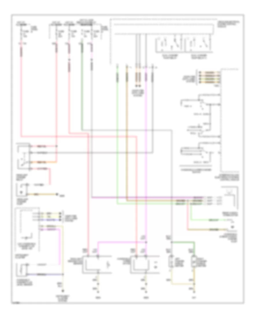 https://portal-diagnostov.com/license.html
Automotive Electricians Portal FZCO
Automotive Electricians Portal FZCO
https://portal-diagnostov.com/license.html
https://portal-diagnostov.com/license.html
Automotive Electricians Portal FZCO
Automotive Electricians Portal FZCOList of elements for Wiper/Washer Wiring Diagram, Late Production for Volkswagen GTI 2006:
- Computer data lines system
- Dual washer pump relay
- Dual washer pump relay 2
- Fuse 10a
- Fuse 15a
- Fuse 20a
- Fuse 5a
- Fuse panel b
- Fuse panel c
- G47
- G605
- G655
- G656
- Headlamp washer pump
- Headlamp washer relay
- Hot at all times
- Hot w/ load reduction relay energized
- Instrument cluster
- Instrument cluster system
- Left washer nozzle heater
- Low windshield washer fluid level ind
- Rain/light recognition sensor
- Rear window wiper motor
- Right washer nozzle heater
- Steering column electronic systems control module
- T20d
- T40
- Vehicle electrical system control module
- Windshield & rear window washer pump
- Windshield washer fluid level sensor
- Windshield wiper motor
- Windshield wiper/washer switch

 Čeština
 Dansk
Dansk Deutsch
 Ελληνικά
 English
 English
 Español
 Suomi
Suomi Français
 Français
 עברית
עברית Hrvatski
 Magyar
 Italiano
 한국어
한국어 Nederlands
 Polski
 Português
 Português
 Română
 Русский
 Slovenčina
 Slovenščina
 Svenska
 Türkçe
 中文 (中国)
