
Jaguar XJS 1995 - 1995 ENGINE PERFORMANCE Self-Diagnostics - 6.0L
Jaguar XJS 1995 - INTRODUCTION
If no faults were found while performing BASIC DIAGNOSTIC PROCEDURES, proceed with self-diagnostics. If no Diagnostic Trouble Codes (DTCs) or only pass codes are present after entering self-diagnostics, proceed to TESTS W/O CODES - 6.0L V12 article for diagnosis by symptom (i.e., ROUGH IDLE, NO START, etc.).
Jaguar XJS 1995 - SELF-DIAGNOSTIC SYSTEM
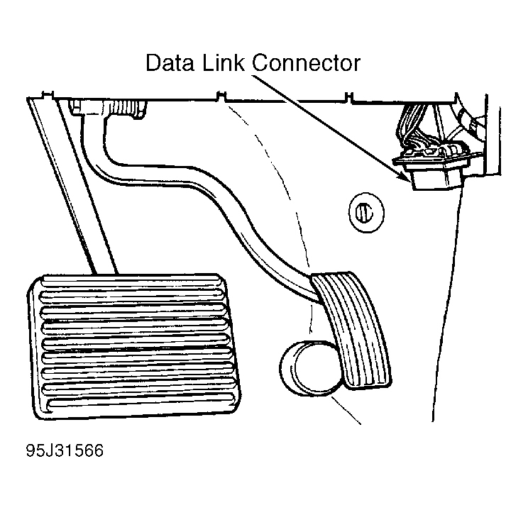
Fig. 1: Jaguar XJS 1995 - Component Locations - Locating 16-Pin Data Link Connector (DLC)
Jaguar XJS 1995 - DIAGNOSTIC TROUBLE CODE IDENTIFICATION
NOTE: Codes listed in DIAGNOSTIC TROUBLE CODE (DTC) IDENTIFICATION TABLE are not used on all vehicles.
Jaguar XJS 1995 DIAGNOSTIC TROUBLE CODE (DTC) IDENTIFICATION
DTC (1) System Affected P0105 High Altitude Compensation Sensor Malfunction P0106 MAP Sensor Range/Performance P0107 MAP Sensor Input Low P0108 MAP Sensor Input High P0111 IAT Sensor Range/Performance P0112 IAT Sensor Input Low P0113 IAT Sensor Input High P0116 ECT Sensor Range/Performance P0117 ECT Sensor Input Low P0118 ECT Sensor Input High P0121 TP Sensor Range/Performance P0122 TP Sensor Input Low P0123 TP Sensor Input High P0125 Excess Time To Enter Closed Loop Fuel Control P0131 Right Front HO2S Circuit Voltage Low P0132 Right Front HO2S Circuit Voltage High P0133 Right Front HO2S Slow Response P0134 Right Front HO2S No Activity Detected P0135 Right Front HO2S Heater Circuit Malfunction P0137 Right Rear HO2S Circuit Voltage Low P0138 Right Rear HO2S Circuit Voltage High P0139 Right Rear HO2S Slow Response P0140 Right Rear HO2S No Activity Detected P0141 Right Rear HO2S Heater Circuit Malfunction P0151 Left Front HO2S Circuit Voltage Low P0152 Left Front HO2S Circuit Voltage High P0153 Left Front HO2S Slow Response P0154 Left Front HO2S No Activity Detected P0155 Left Front HO2S Heater Circuit Malfunction P0157 Left Rear HO2S Circuit Voltage Low P0158 Left Rear HO2S Circuit Voltage High P0159 Left Rear HO2S Slow Response P0160 Left Rear HO2S No Activity Detected P0161 Left Rear HO2S Heater Circuit Malfunction P0171 Right Adaptive Fuel System Too Lean P0172 Right Adaptive Fuel System Too Rich P0174 Left Adaptive Fuel System Too Lean P0175 Left Adaptive Fuel System Too Rich P0201 (2) No. 1 Injector Circuit Malfunction P0202 (2) No. 2 Injector Circuit Malfunction P0203 (2) No. 3 Injector Circuit Malfunction P0204 (2) No. 4 Injector Circuit Malfunction P0205 (2) No. 5 Injector Circuit Malfunction P0206 (2) No. 6 Injector Circuit Malfunction P0207 (3) No. 1 Injector Circuit Malfunction P0208 (3) No. 2 Injector Circuit Malfunction P0209 (3) No. 3 Injector Circuit Malfunction P0210 (3) No. 4 Injector Circuit Malfunction P0211 (3) No. 5 Injector Circuit Malfunction P0212 (3) No. 6 Injector Circuit Malfunction P0300 Random Misfire Detected P0301 (2) Misfire Cylinder No. 1 Detected P0302 (2) Misfire Cylinder No. 2 Detected P0303 (2) Misfire Cylinder No. 3 Detected P0304 (2) Misfire Cylinder No. 4 Detected P0305 (2) Misfire Cylinder No. 5 Detected P0306 (2) Misfire Cylinder No. 6 Detected P0307 (3) Misfire Cylinder No. 1 Detected P0308 (3) Misfire Cylinder No. 2 Detected P0309 (3) Misfire Cylinder No. 3 Detected P0310 (3) Misfire Cylinder No. 4 Detected P0311 (3) Misfire Cylinder No. 5 Detected P0312 (3) Misfire Cylinder No. 6 Detected P0326 KS 1 Circuit Range/Performance P0327 KS 1 Circuit Input Low P0328 KS 1 Circuit Input High P0331 KS 2 Circuit Range/Performance P0332 KS 2 Circuit Input Low P0333 KS 2 Circuit High Input P0335 CKP Sensor Or RPM Sensor Circuit Malfunction P0336 CKP Sensor Or RPM Sensor Range/Performance P0340 CMP Sensor Circuit Malfunction P0400 EGR Function Or Flow Malfunction P0410 Air Injection System Malfunction P0411 Air Injection System Insufficient Flow P0413 Air Injection System Switching Valve Malfunction P0414 Air Injection System Switching Valve Malfunction P0420 Right Catalyst System Efficiency Low P0430 Left Catalyst System Efficiency Low P0441 (2) EVAP Control System Incorrect Purge Flow P0442 EVAP Control System Leak Detected P0443 EVAP Control System Purge Valve Malfunction P0446 EVAP Control System Vent Control Malfunction P0452 EVAP Control System Pressure Sensor Input Low P0453 EVAP Control System Pressure Sensor Malfunction P0500 VSS Circuit Malfunction (XJS) P0500 VSS Circuit Malfunction P0506 (2) ISC System RPM Low P0507 (2) ISC System RPM High P0603 (4) Internal PCM Keep Alive Memory Error P0605 Internal PCM ROM Test Error P0605 Internal TCM Error P0702 (5) Automatic Transaxle P0703 (5) Automatic Transaxle P0705 (5) Automatic Transaxle P0706 (5) Automatic Transaxle P0712 (5) Automatic Transaxle P0713 (5) Automatic Transaxle P0715 (5) Automatic Transaxle P0716 (5) Automatic Transaxle P0720 (5) Automatic Transaxle P0721 (5) Automatic Transaxle P0722 (5) Automatic Transaxle P0726 (5) Automatic Transaxle P0727 (5) Automatic Transaxle P0730 (5) Automatic Transaxle P0741 (5) Automatic Transaxle P0742 (5) Automatic Transaxle P0743 (5) Automatic Transaxle P0748 (5) Automatic Transaxle P0751 (5) Automatic Transaxle P0753 (5) Automatic Transaxle P0756 (5) Automatic Transaxle P0758 (5) Automatic Transaxle P0780 (5) Automatic Transaxle P1000 PCM Check Not Complete Since Last Memory Clear P1106 (3) MAP Sensor Range/Performance P1107 (3) MAP Sensor Input Low P1108 (3) MAP Sensor Input High P1111 PCM Check Complete Since Last Memory Clear P1137 Right Rear O2S Indicates Lean P1138 Right Rear O2S Indicates Rich P1157 Left Rear O2S Indicates Lean P1158 Left Rear O2S Indicates Rich P1171 Adaptive Fuel Lean P1172 Adaptive Fuel Rich P1176 Fuel Mass Flow Rate Lean P1177 Fuel Mass Flow Rate Rich P1178 Air Mass Flow Rate Lean P1179 Air Mass Flow Rate Rich P1185 Front O2S Heater Fault P1186 Front O2S Heater Fault P1187 Front O2S Heater Fault P1188 Front O2S Heater Fault P1189 Front O2S Heater Fault P1190 Front O2S Heater Fault P1191 Rear O2S Heater Fault P1192 Rear O2S Heater Fault P1193 Rear O2S Heater Fault P1194 Rear O2S Heater Fault P1195 Rear O2S Heater Fault P1196 Rear O2S Heater Fault P1198 Fuel Level Input High P1199 Fuel Level Input Low Or Malfunction P1201 No. 1 Fuel Injector Malfunction P1202 No. 2 Fuel Injector Malfunction P1203 No. 3 Fuel Injector Malfunction P1204 No. 4 Fuel Injector Malfunction P1205 No. 5 Fuel Injector Malfunction P1206 No. 6 Fuel Injector Malfunction P1240 Sensor Power Supply Malfunction P1241 Sensor Power Supply Input Low P1242 Sensor Power Supply Input High P1244 High Altitude Compensation Range/Performance P1245 Crank Input Signal Low P1246 Crank Input Signal High P1313 Right Catalyst Damage, Misfire Detected P1314 Left Catalyst Damage, Misfire Detected P1315 Persistent Misfire P1316 Misfire Rate Above Limit P1335 CKP Sensor Malfunction P1336 CKP Sensor Range/Performance P1361 No Activation Ignition Coil Cylinder No. 1 P1362 No Activation Ignition Coil Cylinder No. 2 P1363 No Activation Ignition Coil Cylinder No. 3 P1364 No Activation Ignition Coil Cylinder No. 4 P1365 No Activation Ignition Coil Cylinder No. 5 P1366 No Activation Ignition Coil Cylinder No. 6 P1367 Right Ignition Monitor P1368 Left Ignition Monitor P1371 Early Activation Ignition Coil Cylinder No. 1 P1372 Early Activation Ignition Coil Cylinder No. 2 P1373 Early Activation Ignition Coil Cylinder No. 3 P1374 Early Activation Ignition Coil Cylinder No. 4 P1375 Early Activation Ignition Coil Cylinder No. 5 P1376 Early Activation Ignition Coil Cylinder No. 6 P1400 EGR Valve Position Control P1401 EGR Valve Position Circuit P1408 EGR Function Sensor P1409 EGR Valve Circuit P1440 EVAP Purge Valve Open P1441 EVAP Valve Fault P1443 EVAP Valve Circuit Malfunction P1447 EVAP Valve Flow Fault P1448 EVAP Valve Fault P1454 EVAP System Vacuum Test P1506 (3) ISC System RPM Low P1507 (3) ISC System RPM High P1508 Idle Speed Control Circuit P1509 Idle Speed Control Circuit P1512 Closed Throttle Position Switch Input Low P1513 Closed Throttle Position Switch Input High P1514 PNP Switch High Load Neutral/Drive P1516 PNP Switch Gear Chance Neutral/Drive P1517 PNP Switch Cranking Neutral/Drive P1607 MIL Output Circuit P1608 (5) Automatic Transaxle P1621 ECM Engine Immobilization Instrument Panel Circuit Malfunction P1622 ECM Engine Immobilization Instrument Panel Circuit Malfunction P1641 Fuel Pump Main Relay Malfunction P1646 Sub Fuel Pump Malfunction P1739 (5) Automatic Transaxle P1775 (5) Automatic Transaxle P1776 Ignition Retard Request Duration P1794 (5) Automatic Transaxle System Voltage
(1) If codes appear other than those listed in table, verify code. If code is not listed, replace PCM.
(2) Right cylinder bank on 6.0L.
(3) Left cylinder bank on 6.0L.
(4) Replace PCM.
(5) See DIAGNOSIS - 12-CYL article in AUTOMATIC TRANSMISSIONS.
Jaguar XJS 1995 - FREEZE FRAME DATA
Freeze frame data indicates engine operating conditions when the first malfunction, misfire or fuel trim malfunction was detected.
Jaguar XJS 1995 - CLEARING CODES/PCM RESET PROCEDURE
NOTE: Some models have an anti-theft code built into the radio circuit. Clearing codes cancels clock and radio settings; make note of settings before beginning reset procedure. After PCM reset, the radio will not function until code is entered.
To clear codes or to reset Powertrain Control Module (PCM), use PDU scan tool or generic scan tool following manufacturer's instructions. Codes can also be cleared by turning ignition off and disconnecting negative battery terminal for 30 seconds. Disconnect scan tool from DLC, or reconnect negative battery terminal.
Jaguar XJS 1995 - PCM LOCATION
Powertrain Control Module (PCM) is located in passenger side kick panel PCM cover.
Jaguar XJS 1995 - CONNECTOR IDENTIFICATION
For DLC and PCM connector terminal identification, See Fig. 2 and Fig. 3 . DO NOT backprobe PCM when testing. Place tester probe into contact with terminal, from terminal side of wiring harness connectors in engine compartment. DO NOT puncture wire insulation. For female connectors, just touch terminal lightly with tester probe. DO NOT insert probe into terminal.

Jaguar XJS 1995 - SELF-DIAGNOSTIC TESTS
NOTE: Some driveability problems may have been corrected by manufacturer with a revised Powertrain Control Module (PCM). Prior to replacing PCM in following tests, always check if any Technical Service Bulletins (TSBs) apply to vehicle being tested.
CAUTION: Perform all resistance and voltage tests using a Digital Volt-Ohmmeter (DVOM) with a minimum 10-megohm impedance, unless stated otherwise in test procedures. Ensure ignition switch is in OFF position when performing resistance tests, unless stated otherwise in test procedures.
NOTE: Not all Diagnostic Trouble Codes (DTCs) are applicable to all models. Ensure specified DTC test procedure applies to model being repaired.
Jaguar XJS 1995 - DTC P0105: HIGH ALTITUDE COMPENSATION SENSOR MALFUNCTION
NOTE: Testing information is not available from manufacturer.
Jaguar XJS 1995 - DTC P0106: MAP SENSOR RANGE/PERFORMANCE (RIGHT SIDE - XJ12)
NOTE: After each repair, clear DTCs. See CLEARING CODES/PCM RESET PROCEDURE. Turn ignition off and then on. Read DTCs to verify repair is complete. For DLC and PCM connector terminal identification, see CONNECTOR IDENTIFICATION in this article. For WIRING DIAGRAMS, see WIRING DIAGRAMS at the end of this article.
- Using scan tool, read DTCs. If DTC P0106 is present, turn ignition off. Check for DTC P1111 (PCM CHECK COMPLETE SINCE LAST MEMORY CLEAR). If DTC P1111 is not present, problem may be intermittent. See INTERMITTENTS in TESTS W/O CODES - 6.0L V12 article. If DTC P0106 and DTC P1111 are present, go to next step.
- Disconnect right side MAP sensor connector. Sensor is located at right rear side of engine, attached to linkage bracket. Using DVOM, check Blue/White wire for short circuit to ground between MAP sensor connector and PCM connector. Repair wiring as necessary. If wiring is okay, go to next step.
- Check intake manifold pressure hose for restrictions or damage. Replace hose if necessary. If hose is okay, check intake manifold pressure hose filter for restrictions. Replace filter if necessary. If filter is okay, go to next step.
- Check intake manifold for restrictions or damage. Repair or replace manifold if necessary. If manifold is okay, substitute a known-good right side MAP sensor. Clear DTC's. Turn ignition off and then on. Read DTC's. If DTC P0106 is not present, repair is complete. If DTC P0106 is present, replace PCM.
Jaguar XJS 1995 - DTC P0107: MAP SENSOR INPUT LOW (RIGHT SIDE - XJ12)
NOTE: After each repair, clear DTCs. See CLEARING CODES/PCM RESET PROCEDURE. Turn ignition off and then on. Read DTCs to verify repair is complete. For DLC and PCM connector terminal identification, see CONNECTOR IDENTIFICATION in this article. For WIRING DIAGRAMS, see WIRING DIAGRAMS at the end of this article.
- Using scan tool, read DTCs. If DTC P0107 is present, turn ignition off. Check for DTC P1111 (PCM CHECK COMPLETE SINCE LAST MEMORY CLEAR). If DTC P1111 is not present, problem may be intermittent. See INTERMITTENTS in TESTS W/O CODES - 6.0L V12 article. If DTC P0107 and DTC P1111 are present, go to next step.
- Disconnect right side MAP sensor connector. Sensor is located at right rear side of engine, attached to linkage bracket. Using DVOM, check Blue/White wire, Red/White wire and Black/Green wire for continuity between MAP sensor connector and PCM connector. Repair appropriate wire as necessary. If wiring is okay, go to next step.
- Check Red/White wire for short to Blue/White wire or to Black/Green wire in MAP sensor connector harness. Repair appropriate wire(s) as necessary. If wiring is okay, go to next step.
- Substitute a known-good right side MAP sensor. Clear DTCs. Turn ignition off and then on. Read DTCs. If DTC P0107 is not present, repair is complete. If DTC P0107 is present, replace PCM.
Jaguar XJS 1995 - DTC P0108: MAP SENSOR INPUT HIGH (RIGHT SIDE - XJ12)
NOTE: After each repair, clear DTCs. See CLEARING CODES/PCM RESET PROCEDURE. Turn ignition off and then on. Read DTCs to verify repair is complete. For DLC and PCM connector terminal identification, see CONNECTOR IDENTIFICATION in this article. For WIRING DIAGRAMS, see WIRING DIAGRAMS at the end of this article.
- Using scan tool, read DTCs. If DTC P0108 is present, turn ignition off. Check for DTC P1111 (PCM CHECK COMPLETE SINCE LAST MEMORY CLEAR). If DTC P1111 is not present, problem may be intermittent. See INTERMITTENTS in TESTS W/O CODES - 6.0L V12 article. If DTC P0108 and DTC P1111 are present, go to next step.
- Disconnect right side MAP sensor connector. Sensor is located at right rear side of engine, attached to linkage bracket. Using DVOM, check Blue/White wire, Red/White wire and Black/Green wire for continuity between MAP sensor connector and PCM connector. Repair appropriate wire as necessary. If wiring is okay, go to next step.
- Check Red/White wire, Blue/White wire and Black/Green wire in MAP sensor connector harness for short circuit to battery voltage. Repair appropriate wires as necessary. If wiring is okay, go to next step.
- Substitute a known-good right side MAP sensor. Clear DTCs. Turn ignition off and then on. Read DTCs. If DTC P0108 is not present, repair is complete. If DTC P0108 is present, replace PCM.
Jaguar XJS 1995 - DTC P0111: IAT SENSOR RANGE/PERFORMANCE
NOTE: After each repair, clear DTCs. See CLEARING CODES/PCM RESET PROCEDURE. Turn ignition off and then on. Read DTCs to verify repair is complete. For DLC and PCM connector terminal identification, see CONNECTOR IDENTIFICATION in this article. For WIRING DIAGRAMS, see WIRING DIAGRAMS at the end of this article.
- Using scan tool, read DTCs. If DTC P0111 is present, turn ignition off. Check for DTC P1111 (PCM CHECK COMPLETE SINCE LAST MEMORY CLEAR). If DTC P1111 is not present, problem may be intermittent. See INTERMITTENTS in TESTS W/O CODES - 6.0L V12 article. If DTC P0111 and DTC P1111 are present, go to next step.
- Using scan tool, monitor IAT TEMP RANGE. Using a thermometer, check ambient temperature at IAT sensor. IAT sensor is located on intake air hose. If scan tool reading and thermometer reading do not agree, go to step 9). If readings agree, go to next step.
- Check air intake system for restrictions or damage. Repair air intake system as necessary. If air intake system is okay, turn ignition off and go to next step.
- Ensure IAT sensor harness and connector are not damaged and connections are okay. Repair as necessary. If harness and connector are okay, go to next step.
- Disconnect IAT sensor connector. Using DVOM, check Yellow/Pink wire and Red/Blue wire on XJS, or Black/Green wire and Blue/Purple wire on XJ12 for continuity between IAT sensor connector and PCM connector. Repair appropriate wire(s) as necessary. If wiring is okay, go to next step.
- Check Yellow/Pink wire for short to Red/Blue wire on XJS, or Black/Green wire shorted to Blue/Purple wire on XJ12. Repair appropriate wires as necessary. If wiring is okay, go to next step.
- Check Red/Blue wire on XJS, or Blue/Purple wire on XJ12 for continuity to chassis ground. If continuity is not present, repair appropriate wire as necessary. If wiring is okay, go to next step.
- Check resistance across IAT sensor. Ensure resistance increases as temperature rises. If sensor does not test as specified, replace IAT sensor. If sensor tests as specified, go to next step.
- Substitute a known-good IAT sensor. Clear DTCs. Turn ignition off and then on. Read DTCs. If DTC P0111 is not present, repair is complete. If DTC P0111 is present, replace PCM.
Jaguar XJS 1995 - DTC P0112: IAT SENSOR INPUT LOW
NOTE: After each repair, clear DTCs. See CLEARING CODES/PCM RESET PROCEDURE. Turn ignition off and then on. Read DTCs to verify repair is complete. For DLC and PCM connector terminal identification, see CONNECTOR IDENTIFICATION in this article. For WIRING DIAGRAMS, see WIRING DIAGRAMS at the end of this article.
- Using scan tool, read DTCs. If DTC P0112 is present, turn ignition off. Check for DTC P1111 (PCM CHECK COMPLETE SINCE LAST MEMORY CLEAR). If DTC P1111 is not present, problem may be intermittent. See INTERMITTENTS in TESTS W/O CODES - 6.0L V12 article. If DTC P0112 and DTC P1111 are present, go to next step.
- Using scan tool, monitor IAT TEMP RANGE. Using a thermometer, check ambient temperature at IAT sensor. IAT sensor is located on intake air hose. If scan tool reading and thermometer reading do not agree, go to step 8). If readings agree, go to next step.
- Check air intake system for restrictions or damage. Repair air intake system as necessary. If air intake system is okay, turn ignition off and go to next step.
- Ensure IAT sensor harness and connector are not damaged and connections are okay. Repair as necessary. If harness and connectors are okay, go to next step.
- Disconnect IAT sensor connector. Using DVOM, check Yellow/Pink wire and Red/Blue wire on XJS, or Black/Green wire and Blue Purple wire on XJ12 for continuity between IAT sensor connector and PCM connector. Repair appropriate wire as necessary. If wiring is okay, go to next step.
- Check Yellow/Pink wire for short to Red/Blue wire on XJS, or Black/Green wire shorted to Blue/Purple wire on XJ12. Repair appropriate wires as necessary. If wiring is okay, go to next step.
- Check resistance across IAT sensor. Ensure resistance increases as temperature rises. If sensor does not test as specified, replace IAT sensor. If sensor tests as specified, go to next step.
- Substitute a known-good IAT sensor. Clear DTCs. Turn ignition off and then on. Read DTCs. If DTC P0112 is not present, repair is complete. If DTC P0112 is present, replace PCM.
Jaguar XJS 1995 - DTCS P0113: IAT SENSOR INPUT HIGH
NOTE: After each repair, clear DTCs. See CLEARING CODES/PCM RESET PROCEDURE. Turn ignition off and then on. Read DTCs to verify repair is complete. For DLC and PCM connector terminal identification, see CONNECTOR IDENTIFICATION in this article. For WIRING DIAGRAMS, see WIRING DIAGRAMS at the end of this article.
- Using scan tool, read DTCs. If DTC P0113 is present, turn ignition off. Check for DTC P1111 (PCM CHECK COMPLETE SINCE LAST MEMORY CLEAR). If DTC P1111 is not present, problem may be intermittent. See INTERMITTENTS in TESTS W/O CODES - 6.0L V12 article. If DTC P0113 and DTC P1111 are present, go to next step.
- Using scan tool, monitor IAT TEMP RANGE. Using a thermometer, check ambient temperature at IAT sensor. IAT sensor is located on intake air hose. If scan tool reading and thermometer reading do not agree, go to step 7). If readings agree, go to next step.
- Check air intake system for restrictions or damage. Repair air intake system as necessary. If air intake system is okay, turn ignition off and go to next step.
- Disconnect IAT sensor connector. Using DVOM, check Yellow/Pink wire and Red/Blue wire on XJS, or Black/Green wire and Blue/Purple wire on XJ12 for continuity between IAT sensor connector and PCM connector. Repair appropriate wire(s) as necessary. If wiring is okay, go to next step.
- Check Yellow/Pink wire for short to Red/Blue wire on XJS, or Black/Green wire shorted to Blue/Purple wire on XJ12. Repair appropriate wires as necessary. If wiring is okay, go to next step.
- Check resistance across IAT sensor. Ensure resistance increases as temperature rises. If sensor does not test as specified, replace IAT sensor. If sensor tests as specified, go to next step.
- Substitute a known-good IAT sensor. Clear DTCs. Turn ignition off and then on. Read DTCs. If DTC P0111 is not present, repair is complete. If DTC P0111 is present, replace PCM.
Jaguar XJS 1995 - DTC P0116: ECT SENSOR RANGE/PERFORMANCE
NOTE: After each repair, clear DTCs. See CLEARING CODES/PCM RESET PROCEDURE. Turn ignition off and then on. Read DTCs to verify repair is complete. For DLC and PCM connector terminal identification, see CONNECTOR IDENTIFICATION in this article. For WIRING DIAGRAMS, see WIRING DIAGRAMS at the end of this article.
- Using scan tool, read DTCs. If DTC P0116 is present, turn ignition off. Check for DTC P1111 (PCM CHECK COMPLETE SINCE LAST MEMORY CLEAR). If DTC P1111 is not present, problem may be intermittent. See INTERMITTENTS in TESTS W/O CODES - 6.0L V12 article. If DTC P0116 and DTC P1111 are present, go to next step.
- Turn ignition off. Check and adjust coolant level as necessary. If coolant level is okay, check and repair coolant temperature gauge operation as necessary. If gauge is okay, go to next step.
- Remove thermostat and check thermostat operation. Replace thermostat if necessary. If thermostat is okay, disconnect ECT sensor and go to next step.
- Using DVOM, check Yellow/Black wire for continuity between ECT sensor connector terminal No. 1 and PCM connector terminal No. 1 wire on XJS, or Black/Green wire between ECT sensor connector terminal No. 1 and PCM connector terminal No. 16 on XJ12. Repair appropriate wire as necessary. If wiring is okay, go to next step.
- Check Blue/Orange wire on XJS, or Blue/Yellow wire on XJ12 for continuity between ECT sensor connector terminal No. 2 and PCM connector terminal No. 5. Repair appropriate wire as necessary. If wiring is okay, go to next step.
- Check Yellow/Black wire for short to Blue/Orange wire on XJS, or Black/Green wire shorted to Blue/Yellow wire on XJ12. Repair appropriate wires as necessary. If wiring is okay, go to next step.
- Check resistance across ECT sensor connector terminals. Resistance should be 2045 ohms with coolant at 68?F (20?C), 318 ohms at 176?F (80?C), or 142 ohms at 230?F (110?C). If sensor does not test as specified, replace ECT sensor. If sensor tests as specified, go to next step.
- Clear DTCs. Turn ignition off and then on. Read DTCs. If DTC P0116 is not present, repair is complete. If DTC P0116 is present, replace PCM.
Jaguar XJS 1995 - DTC P0117: ECT SENSOR INPUT LOW
NOTE: After each repair, clear DTCs. See CLEARING CODES/PCM RESET PROCEDURE. Turn ignition off and then on. Read DTCs to verify repair is complete. For DLC and PCM connector terminal identification, see CONNECTOR IDENTIFICATION in this article. For WIRING DIAGRAMS, see WIRING DIAGRAMS at the end of this article.
- Using scan tool, read DTCs. If DTC P0117 is present, turn ignition off. Check for DTC P1111 (PCM CHECK COMPLETE SINCE LAST MEMORY CLEAR). If DTC P1111 is not present, problem may be intermittent. See INTERMITTENTS in TESTS W/O CODES - 6.0L V12 article. If DTC P0117 and DTC P1111 are present, go to next step.
- Using scan tool, monitor ECT RANGE. Using a thermometer, check coolant temperature. If scan tool reading and thermometer reading do not agree, go to step 5). If readings agree, go to next step.
- Turn ignition off. Disconnect ECT sensor connector. Using DVOM, check Yellow/Black wire for continuity between ECT sensor connector terminal No. 1 and PCM connector terminal No. 1 on XJS, or Black/Green wire between ECT sensor connector terminal No. 1 and PCM connector terminal No. 16 on XJ12. Repair appropriate wire as necessary. If wiring is okay, go to next step.
- Check Blue/Orange wire on XJS or Blue/Yellow wire on XJ12 for continuity between ECT sensor connector terminal No.2 and PCM connector terminal No. 5. Repair appropriate wire as necessary. If wiring is okay, go to next step.
- Check resistance across ECT sensor connector terminals. Resistance should be 2045 ohms with coolant at 68?F (20?C), 318 ohms at 176?F (80?C), or 142 ohms at 230?F (110?C). If sensor does not test as specified, replace ECT sensor. If sensor tests as specified, go to next step.
- Clear DTCs. Turn ignition off and then on. Read DTCs. If DTC P0117 is not present, repair is complete. If DTC P0117 is present, replace PCM.
Jaguar XJS 1995 - DTC P0118: ECT SENSOR INPUT HIGH
NOTE: After each repair, clear DTCs. See CLEARING CODES/PCM RESET PROCEDURE. Turn ignition off and then on. Read DTCs to verify repair is complete. For DLC and PCM connector terminal identification, see CONNECTOR IDENTIFICATION in this article. For WIRING DIAGRAMS, see WIRING DIAGRAMS at the end of this article.
- Using scan tool, read DTCs. If DTC P0118 is present, turn ignition off. Check for DTC P1111 (PCM CHECK COMPLETE SINCE LAST MEMORY CLEAR). If DTC P1111 is not present, problem may be intermittent. See INTERMITTENTS in TESTS W/O CODES - 6.0L V12 article. If DTC P0118 and DTC P1111 are present, go to next step.
- Using scan tool, monitor ECT RANGE. Using a thermometer, check coolant temperature. If scan tool reading and thermometer reading do not agree, go to step 8). If readings agree, go to next step.
- Turn ignition off. Disconnect ECT sensor connector. Using DVOM, check Yellow/Black wire on XJS for continuity between ECT sensor connector terminal No. 1 and PCM connector terminal No. 1, or Black/Green wire on XJ12 between ECT sensor connector terminal No. 1 and PCM connector terminal No. 16. Repair appropriate wire as necessary. If wiring is okay, go to next step.
- Check Blue/Orange wire on XJS or Blue/Yellow wire on XJ12 for continuity between ECT sensor connector terminal No.2 and PCM connector terminal No. 5. Repair appropriate wire as necessary. If wiring is okay, go to next step.
- Check Yellow/Black wire for short to Blue/Orange wire on XJS, or Black/Green wire shorted to Blue/Yellow wire on XJ12. Repair appropriate wires as necessary. If wiring is okay, go to next step.
- Check Yellow/Black wire on XJS or Black/Green wire on XJ12 for short circuit to battery voltage. Repair wiring as necessary. If wiring is okay, go to next step.
- Check Blue/Orange wire on XJS or Blue/Yellow wire on XJ12 for short circuit to battery voltage. Repair wiring as necessary. If wiring is okay, go to next step.
- Check resistance across ECT sensor connector terminals. Resistance should be 2045 ohms with coolant at 68?F (20?C), 318 ohms at 176?F (80?C), or 142 ohms at 230?F (110?C). If sensor does not test as specified, replace ECT sensor. If sensor tests as specified, go to next step.
- Clear DTCs. Turn ignition off and then on. Read DTCs. If DTC P0117 is not present, repair is complete. If DTC P0118 is present, replace PCM.
Jaguar XJS 1995 - DTC P0121: TP SENSOR RANGE/PERFORMANCE
NOTE: After each repair, clear DTCs. See CLEARING CODES/PCM RESET PROCEDURE. Turn ignition off and then on. Read DTCs to verify repair is complete. For DLC and PCM connector terminal identification, see CONNECTOR IDENTIFICATION in this article. For WIRING DIAGRAMS, see WIRING DIAGRAMS at the end of this article.
Jaguar XJS 1995 - XJ12
- Using scan tool, read DTCs. If DTC P0121 is present, turn ignition off. Check for DTC P1111 (PCM CHECK COMPLETE SINCE LAST MEMORY CLEAR). If DTC P1111 is not present, problem may be intermittent. See INTERMITTENTS in TESTS W/O CODES - 6.0L V12 article. If DTC P0121 and DTC P1111 are present, go to next step.
- Using scan tool, monitor TP values at open throttle and at closed throttle. If values are not okay, replace or adjust TP sensor as necessary. If values are okay, go to next step.
- Turn ignition off. Disconnect TP sensor connector. Turn ignition on. Using DVOM, check Blue/White wire for voltage at TP sensor connector terminal No. 4. If voltage is not 5 volts, Repair wiring as necessary. If voltage is 5 volts, go to next step.
- Check Black/Green wire for voltage at TP sensor connector terminal No. 1. If any voltage is present, Repair wiring as necessary. If no voltage is present, turn ignition off and go to next step.
- Check Orange/Yellow wire for continuity between TP sensor connector terminal No. 2 and PCM connector terminal No. 3. Repair wiring as necessary. If wiring is okay, check Green/Yellow wire for continuity between TP sensor connector terminal No. 3 and PCM connector terminal No. 4. Repair wiring as necessary. If wiring is okay, go to next step.
- Check Green/Yellow wire at TP sensor connector terminal No. 3 for short to Black/Green wire at TP sensor connector terminal No. 1. Repair wiring as necessary. If wiring is okay, check at TP sensor connector terminal No. 3 for short to Blue/White wire at TP sensor connector terminal No. 4. Repair wiring as necessary. If wiring is okay, go to next step.
- Connect DVOM between TP sensor terminals No. 1 (Black/Green wire) and TP sensor terminal No. 3 (Green/Yellow wire). While monitoring DVOM display, slowly move throttle from closed to open position. If voltage does not increase smoothly, replace TP sensor. If voltage increases smoothly, go to next step.
- Check air inlet system and exhaust system for blockage. Repair as necessary. Repair appropriate system as necessary.If both systems are okay, go to next step.
- Substitute a known-good TP sensor. Clear DTCs. Turn ignition off and then on. Read DTCs. If DTC P0121 is not present, repair is complete. If DTC P0121 is present, replace PCM.
Jaguar XJS 1995 - DTC P0122: THROTTLE POSITION (TP) SENSOR INPUT LOW
NOTE: After each repair, clear DTCs. See CLEARING CODES/PCM RESET PROCEDURE. Turn ignition off and then on. Read DTCs to verify repair is complete. For DLC and PCM connector terminal identification, see CONNECTOR IDENTIFICATION in this article. For WIRING DIAGRAMS, see WIRING DIAGRAMS at the end of this article.
Jaguar XJS 1995 - XJ12
- Using scan tool, read DTCs. If DTC P0122 is present, turn ignition off. Check for DTC P1111 (PCM CHECK COMPLETE SINCE LAST MEMORY CLEAR). If DTC P1111 is not present, problem may be intermittent. See INTERMITTENTS in TESTS W/O CODES - 6.0L V12 article. If DTC P0122 and DTC P1111 are present, go to next step.
- Using scan tool, monitor TP values at open throttle and at closed throttle. If values are not okay, replace or adjust TP sensor as necessary. If values are okay, go to next step.
- Turn ignition off. Disconnect TP sensor. Turn ignition on. Using DVOM, check Blue/White wire for voltage at TP sensor connector terminal No. 4. If voltage is not 5 volts, Repair wiring as necessary. If voltage is 5 volts, go to next step.
- Check Black/Green wire for voltage at TP sensor connector terminal No. 1. If any voltage is present, Repair wiring as necessary. If no voltage is present, turn ignition off and go to next step.
- Check Orange/Yellow wire for continuity between TP sensor connector terminal No. 2 and PCM connector terminal No. 3. Repair wiring as necessary. If wiring is okay, check Green/Yellow wire for continuity between TP sensor connector terminal No. 3 and PCM connector terminal No. 4. Repair wiring as necessary. If wiring is okay, go to next step.
- Check Green/Yellow wire at TP sensor connector terminal No. 3 for short to Black/(Green wire) shorted at TP sensor connector terminal No. 1. Repair wiring as necessary. If wiring is okay, check for TP sensor connector terminal No. 3 shorted Blue/White wire at TP sensor connector terminal No. 4. Repair wires as necessary. If wiring is okay, go to next step.
- Check Green/Yellow wire at TP sensor terminal No. 3 for short to Black/Green wire at TP sensor terminal No. 1, and TP sensor terminal No. 3 shorted to Blue/White wire at TP sensor terminal No. 4. If any short is present, replace TP sensor. If no shorts are present, go to next step.
- Check Green/Yellow wire at TP sensor connector terminal No. 3 for short to battery voltage. Repair wiring as necessary. If wiring is okay, Check inlet air system and exhaust system for blockage. Repair appropriate system as necessary. If systems are okay, go to next step.
- Substitute a known-good TP sensor. Clear DTCs. Turn ignition off and then on. Read DTCs. If DTC P0122 is not present, repair is complete. If DTC P0123 is present, replace PCM.
Jaguar XJS 1995 - DTC P0123: THROTTLE POSITION (TP) SENSOR INPUT HIGH
NOTE: After each repair, clear DTCs. See CLEARING CODES/PCM RESET PROCEDURE. Turn ignition off and then on. Read DTCs to verify repair is complete. For DLC and PCM connector terminal identification, see CONNECTOR IDENTIFICATION in this article. For WIRING DIAGRAMS, see WIRING DIAGRAMS at the end of this article.
Jaguar XJS 1995 - XJ12
- Using scan tool, read DTCs. If DTC P0123 is present, turn ignition off. Check for DTC P1111 (PCM CHECK COMPLETE SINCE LAST MEMORY CLEAR). If DTC P1111 is not present, problem may be intermittent. See INTERMITTENTS in TESTS W/O CODES - 6.0L V12 article. If DTC P0123 and DTC P1111 are present, go to next step.
- Using scan tool, monitor TP values at open throttle and at closed throttle. If values are not okay, replace or adjust TP sensor as necessary. If values are okay, go to next step.
- Turn ignition off. Disconnect TP sensor. Turn ignition on. Using DVOM, check Blue/White wire for voltage at TP sensor connector terminal No. 4. If voltage is not 5 volts, Repair wiring as necessary. If voltage is 5 volts, go to next step.
- Check Black/Green wire for voltage at TP sensor connector terminal No. 1. If any voltage is present, Repair wiring as necessary. If no voltage is present, turn ignition off and go to next step.
- Check Orange/Yellow wire for continuity between TP sensor connector terminal No. 2 and PCM connector terminal No. 3. Repair wiring as necessary. If wiring is okay, check Green/Yellow wire for continuity between TP sensor connector terminal No. 3 and PCM connector terminal No. 4. Repair wiring as necessary. If wiring is okay, go to next step.
- Check Green/Yellow wire at TP sensor connector terminal No. 3 for short to Black/(Green wire) shorted at TP sensor connector terminal No. 1. Repair wiring as necessary. If wiring is okay, check for TP sensor connector terminal No. 3 shorted Blue/White wire at TP sensor connector terminal No. 4. Repair wires as necessary. If wiring is okay, go to next step.
- Check Green/Yellow wire at TP sensor terminal No. 3 for short to Black/Green wire at TP sensor terminal No. 1, and TP sensor terminal No. 3 shorted to Blue/White wire at TP sensor terminal No. 4. If any short is present, replace TP sensor. If no shorts are present, go to next step.
- Check Green/Yellow wire at TP sensor connector terminal No. 3 for short to battery voltage. Repair wiring as necessary. If wiring is okay, Check inlet air system and exhaust system for blockage. Repair appropriate system as necessary. If systems are okay, go to next step.
- Substitute a known-good TP sensor. Clear DTCs. Turn ignition off and then on. Read DTCs. If DTC P0123 is not present, repair is complete. If DTC P0123 is present, replace PCM.
Jaguar XJS 1995 - DTC P0125: EXCESS TIME TO ENTER CLOSED LOOP FUEL CONTROL
NOTE: After each repair, clear DTCs. See CLEARING CODES/PCM RESET PROCEDURE. Turn ignition off and then on. Read DTCs to verify repair is complete. For DLC and PCM connector terminal identification, see CONNECTOR IDENTIFICATION in this article. For WIRING DIAGRAMS, see WIRING DIAGRAMS at the end of this article.
- Using scan tool, read DTCs. If DTC P0125 is present, turn ignition off. Check for DTC P1111 (PCM CHECK COMPLETE SINCE LAST MEMORY CLEAR). If DTC P1111 is not present, problem may be intermittent. See INTERMITTENTS in TESTS W/O CODES - 6.0L V12 article. If DTC P0125 and DTC P1111 are present, go to next step.
- Turn ignition off. Check and adjust coolant level as necessary. If coolant level is okay, check and repair coolant temperature gauge operation as necessary. If gauge is okay, go to next step.
- Remove thermostat and check thermostat operation. Replace thermostat if necessary. If thermostat is okay, disconnect ECT sensor and go to next step.
- Using DVOM, check Yellow/Black wire for continuity between ECT sensor connector terminal No. 1 and PCM connector terminal No. 1 wire on XJS, or Black/Green wire between ECT sensor connector terminal No. 1 and PCM connector terminal No. 16 on XJ12. Repair appropriate wire as necessary. If wiring is okay, go to next step.
- Check Yellow/Black wire for short to Blue/Orange wire on XJS, or Black/Green wire shorted to Blue/Yellow wire on XJ12. Repair appropriate wires as necessary. If wiring is okay, go to next step.
- Check resistance across ECT sensor connector terminals. Resistance should be 2045 ohms with coolant at 68?F (20?C), 318 ohms at 176?F (80?C), or 142 ohms at 230?F (110?C). If sensor does not test as specified, replace ECT sensor. If sensor tests as specified, go to next step.
- Clear DTCs. Turn ignition off and then on. Read DTCs. If DTC P0125 is not present, repair is complete. If DTC P0125 is present, replace PCM.
Jaguar XJS 1995 - DTC P0131: RIGHT FRONT HO2S CIRCUIT VOLTAGE LOW
NOTE: After each repair, clear DTCs. See CLEARING CODES/PCM RESET PROCEDURE. Turn ignition off and then on. Read DTCs to verify repair is complete. For DLC and PCM connector terminal identification, see CONNECTOR IDENTIFICATION in this article. For WIRING DIAGRAMS, see WIRING DIAGRAMS at the end of this article.
Jaguar XJS 1995 - XJ12
- Using scan tool, read DTCs. If DTC P0131 is present, turn ignition off. Check for DTC P1111 (PCM CHECK COMPLETE SINCE LAST MEMORY CLEAR). If DTC P1111 is not present, problem may be intermittent. See INTERMITTENTS in TESTS W/O CODES - 6.0L V12 article. If DTC P0131 and DTC P1111 are present, go to next step.
- Disconnect Right Front (RF) HO2S connector. Using DVOM, check Red wire for continuity between RF HO2S connector terminal No. 3 and PCM connector terminal No. 11. Repair wiring as necessary. If wiring is okay, check Black/Purple wire (at PCM) between PCM connector terminal No. 15 and RF HO2S connector terminal No. 4 (no wire color available at RF HO2S connector). Repair wiring as necessary. If wiring is okay, check RF HO2S connector terminal No. 3 for short circuit to ground. Repair wiring as necessary. If wiring is okay, go to next step.
- Check resistance across RF HO2S terminals No. 1 and No. 2. If resistance is not 10,000-20,000 ohms at 68-212?F (20-100?C), replace HO2S. If resistance is as specified, go to next step.
- Check RF HO2S terminal No. 4 for good ground. Repair ground circuit as necessary. If a good ground is present, go to next step.
- Substitute a known-good HO2S. Clear DTCs. Turn ignition off and then on. Read DTCs. If DTC P0131 is not present, repair is complete. If DTC P0131 is present, replace PCM.
Jaguar XJS 1995 - DTC P0132: RIGHT FRONT HO2S CIRCUIT VOLTAGE HIGH
NOTE: After each repair, clear DTCs. See CLEARING CODES/PCM RESET PROCEDURE. Turn ignition off and then on. Read DTCs to verify repair is complete. For DLC and PCM connector terminal identification, see CONNECTOR IDENTIFICATION in this article. For WIRING DIAGRAMS, see WIRING DIAGRAMS at the end of this article.
Jaguar XJS 1995 - XJ12
- Using scan tool, read DTCs. If DTC P0132 is present, turn ignition off. Check for DTC P1111 (PCM CHECK COMPLETE SINCE LAST MEMORY CLEAR). If DTC P1111 is not present, problem may be intermittent. See INTERMITTENTS in TESTS W/O CODES - 6.0L V12 article. If DTC P0132 and DTC P1111 are present, go to next step.
- Disconnect Right Front (RF) HO2S connector. Using DVOM, check Black/Purple wire (at PCM) between PCM connector terminal No. 15 and RF HO2S connector terminal No. 4 (no wire color available at RF HO2S connector). Repair wiring as necessary. If wiring is okay, turn ignition on and go to next step.
- Ensure no voltage is present on Black/Purple wire at PCM terminal No. 15. If voltage is present, Repair wiring as necessary. If no voltage is present, Check RF HO2S connector terminal No. 3 for short to battery voltage. Repair wiring as necessary. If wiring is okay, go to next step.
- Substitute a known-good HO2S. Clear DTCs. Turn ignition off and then on. Read DTCs. If DTC P0132 is not present, repair is complete. If DTC P0132 is present, replace PCM.
Jaguar XJS 1995 - DTC P0133: RIGHT FRONT HO2S SLOW RESPONSE
NOTE: After each repair, clear DTCs. See CLEARING CODES/PCM RESET PROCEDURE. Turn ignition off and then on. Read DTCs to verify repair is complete. For DLC and PCM connector terminal identification, see CONNECTOR IDENTIFICATION in this article. For WIRING DIAGRAMS, see WIRING DIAGRAMS at the end of this article.
Jaguar XJS 1995 - XJ12
- Using scan tool, read DTCs. If DTC P0133 is present, turn ignition off. Check for DTC P1111 (PCM CHECK COMPLETE SINCE LAST MEMORY CLEAR). If DTC P1111 is not present, problem may be intermittent. See INTERMITTENTS in TESTS W/O CODES - 6.0L V12 article. If DTC P0133 and DTC P1111 are present, go to next step.
- Disconnect Right Front (RF) HO2S connector. Using DVOM, check Red wire for continuity between RF HO2S connector terminal No. 3 and PCM connector terminal No. 11. Repair wiring as necessary. If wiring is okay, check Black/Purple wire (at PCM) between PCM connector terminal No. 15 and RF HO2S connector terminal No. 4 (no wire color available at RF HO2S connector). Repair wiring as necessary. If wiring is okay, go to next step.
- Check RF HO2S connector terminal No. 3 for short circuit to battery voltage. Repair wiring as necessary. If wiring is okay, check RF HO2S connector terminal No 4 for short to battery voltage. Repair wiring as necessary. If wiring is okay, go to next step.
- Check RF HO2S connector terminal No. 3 for short to ground. Repair wiring as necessary. If wiring is okay, turn ignition on and go to next step.
- Ensure no voltage is present on RF HO2S connector terminal No. 4 (no wire color is available). If voltage is present, Repair wiring as necessary. If no voltage is present, check resistance across RF HO2S terminals No. 1 and No. 2. If resistance is not 10,000-20,000 ohms at 68-212?F (20-100?C), replace HO2S. If resistance is as specified, go to next step.
- Substitute a known-good HO2S. Clear DTCs. Turn ignition off and then on. Read DTCs. If DTC P0133 is not present, repair is complete. If DTC P0133 is present, replace PCM.
Jaguar XJS 1995 - DTC P0134: RIGHT FRONT HO2S NO ACTIVITY DETECTED (XJ12)
NOTE: After each repair, clear DTCs. See CLEARING CODES/PCM RESET PROCEDURE. Turn ignition off and then on. Read DTCs to verify repair is complete. For DLC and PCM connector terminal identification, see CONNECTOR IDENTIFICATION in this article. For WIRING DIAGRAMS, see WIRING DIAGRAMS at the end of this article.
- Using scan tool, read DTCs. If DTC P0134 is present, turn ignition off. Check for DTC P1111 (PCM CHECK COMPLETE SINCE LAST MEMORY CLEAR). If DTC P1111 is not present, problem may be intermittent. See INTERMITTENTS in TESTS W/O CODES - 6.0L V12 article. If DTC P0134 and DTC P1111 are present, go to next step.
- Disconnect Right Front (RF) HO2S connector. Using DVOM, check Red wire for continuity between RF HO2S connector terminal No. 3 and PCM connector terminal No. 11. Repair wiring as necessary. If wiring is okay, check Black/Purple wire (at PCM) between PCM connector terminal No. 15 and RF HO2S connector terminal No. 4 (no wire color available at RF HO2S connector). Repair wiring as necessary. If wiring is okay, go to next step.
- Check RF HO2S connector terminal No. 3 for short circuit to battery voltage. Repair wiring as necessary. If wiring is okay, check RF HO2S connector terminal No 4 for short to battery voltage. Repair wiring as necessary. If wiring is okay, go to next step.
- Check RF HO2S connector terminal No. 3 for short to ground. Repair wiring as necessary. If wiring is okay, turn ignition on and go to next step.
- Ensure no voltage is present on RF HO2S connector terminal No. 4 (no wire color is available). If voltage is present, Repair wiring as necessary. If no voltage is present, check resistance across RF HO2S terminals No. 1 and No. 2. If resistance is not 10,000-20,000 ohms at 68-212?F (20-100?C), replace HO2S. If resistance is as specified, go to next step.
- Substitute a known-good HO2S. Clear DTCs. Turn ignition off and then on. Read DTCs. If DTC P0134 is not present, repair is complete. If DTC P0134 is present, replace PCM.
Jaguar XJS 1995 - DTC P0135: RIGHT FRONT HO2S HEATER CIRCUIT MALFUNCTION (XJ12)
NOTE: After each repair, clear DTCs. See CLEARING CODES/PCM RESET PROCEDURE. Turn ignition off and then on. Read DTCs to verify repair is complete. For DLC and PCM connector terminal identification, see CONNECTOR IDENTIFICATION in this article. For WIRING DIAGRAMS, see WIRING DIAGRAMS at the end of this article.
- Using scan tool, read DTCs. If DTC P0135 is present, turn ignition off. Check for DTC P1111 (PCM CHECK COMPLETE SINCE LAST MEMORY CLEAR). If DTC P1111 is not present, problem may be intermittent. See INTERMITTENTS in TESTS W/O CODES - 6.0L V12 article. If DTC P0135 and DTC P1111 are present, go to next step.
- Turn ignition off and disconnect Right Front (RF) HO2S connector. Using DVOM, check Purple/Blue wire for continuity between RF HO2S connector terminal No. 1 and PCM connector terminal No. 6. Repair wiring as necessary. If wiring is okay, use DVOM and wiring diagram to check continuity of White/Green wire between RF HO2S connector terminal No. 2 and all other circuit related components. Repair wiring as necessary. If wiring is okay, go to next step.
- Check RF HO2S terminal No. 1 for short to ground. Repair wiring as necessary. If wiring is okay, use wiring diagram to check RF HO2S connector terminal No. 2 and all other circuit related components for short to ground. Repair wiring as necessary. If wiring is okay, go to next step.
- Check RF HO2S terminal No. 1 for short to battery. Repair wiring as necessary. If wiring is okay, use wiring diagram to check RF HO2S connector terminal No. 2 and all other circuit related components for short to battery. Repair wiring as necessary. If wiring is okay, go to next step.
- Check resistance across RF HO2S terminals No. 1 and No. 2. If resistance is not 10,000-20,000 ohms at 68-212?F (20-100?C), replace HO2S. If resistance is as specified, go to next step.
- Substitute a known-good HO2S. Clear DTCs. Turn ignition off and then on. Read DTCs. If DTC P0135 is not present, repair is complete. If DTC P0135 is present, replace PCM.
Jaguar XJS 1995 - DTC P0137: RIGHT REAR HO2S CIRCUIT VOLTAGE LOW
NOTE: After each repair, clear DTCs. See CLEARING CODES/PCM RESET PROCEDURE. Turn ignition off and then on. Read DTCs to verify repair is complete. For DLC and PCM connector terminal identification, see CONNECTOR IDENTIFICATION in this article. For WIRING DIAGRAMS, see WIRING DIAGRAMS at the end of this article.
Jaguar XJS 1995 - XJ12
- Using scan tool, read DTCs. If DTC P0137 is present, turn ignition off. Check for DTC P1111 (PCM CHECK COMPLETE SINCE LAST MEMORY CLEAR). If DTC P1111 is not present, problem may be intermittent. See INTERMITTENTS in TESTS W/O CODES - 6.0L V12 article. If DTC P0137 and DTC P1111 are present, go to next step.
- Disconnect Right Rear (RR) HO2S connector. Using DVOM, check Blue wire for continuity between RR HO2S connector terminal No. 3 and PCM connector terminal No. 9. Repair wiring as necessary. If wiring is okay, check Black/Purple wire (at PCM) between PCM connector terminal No. 15 and RR HO2S connector terminal No. 4 (no wire color available at RR HO2S connector). Repair wiring as necessary. If wiring is okay, go to next step. Check RR HO2S connector terminal No. 3 for short circuit to ground. Repair wiring as necessary. If wiring is okay, go to next step.
- Check resistance across RR HO2S terminals No. 1 and No. 2. If resistance is not 10,000-20,000 ohms at 68-212?F (20-100?C), replace HO2S. If resistance is as specified, go to next step.
- Check RR HO2S terminal No. 4 for good ground. Repair ground circuit as necessary. If a good ground is present, go to next step.
- Substitute a known-good HO2S. Clear DTCs. Turn ignition off and then on. Read DTCs. If DTC P0137 is not present, repair is complete. If DTC P0137 is present, replace PCM.
Jaguar XJS 1995 - DTC P0138: RIGHT REAR HO2S CIRCUIT VOLTAGE HIGH
NOTE: After each repair, clear DTCs. See CLEARING CODES/PCM RESET PROCEDURE. Turn ignition off and then on. Read DTCs to verify repair is complete. For DLC and PCM connector terminal identification, see CONNECTOR IDENTIFICATION in this article. For WIRING DIAGRAMS, see WIRING DIAGRAMS at the end of this article.
Jaguar XJS 1995 - XJ12
- Using scan tool, read DTCs. If DTC P0138 is present, turn ignition off. Check for DTC P1111 (PCM CHECK COMPLETE SINCE LAST MEMORY CLEAR). If DTC P1111 is not present, problem may be intermittent. See INTERMITTENTS in TESTS W/O CODES - 6.0L V12 article. If DTC P0138 and DTC P1111 are present, go to next step.
- Disconnect Right Rear (RR) HO2S connector. Using DVOM, check Black/Purple wire (at PCM) between PCM connector terminal No. 15 and RR HO2S connector terminal No. 4 (no wire color available at RR HO2S connector). Repair wiring as necessary. If wiring is okay, turn ignition on and go to next step.
- Ensure no voltage is present on Black/Purple wire at PCM terminal No. 15. If voltage is present, Repair wiring as necessary. If no voltage is present, Check RR HO2S connector terminal No. 3 for short to battery voltage. Repair wiring as necessary. If wiring is okay, go to next step.
- Substitute a known-good HO2S. Clear DTCs. Turn ignition off and then on. Read DTCs. If DTC P0138 is not present, repair is complete. If DTC P0138 is present, replace PCM.
Jaguar XJS 1995 - DTC P0139: RIGHT REAR HO2S SLOW RESPONSE
NOTE: After each repair, clear DTCs. See CLEARING CODES/PCM RESET PROCEDURE. Turn ignition off and then on. Read DTCs to verify repair is complete. For DLC and PCM connector terminal identification, see CONNECTOR IDENTIFICATION in this article. For WIRING DIAGRAMS, see WIRING DIAGRAMS at the end of this article.
Jaguar XJS 1995 - XJ12
- Using scan tool, read DTCs. If DTC P0139 is present, turn ignition off. Check for DTC P1111 (PCM CHECK COMPLETE SINCE LAST MEMORY CLEAR). If DTC P1111 is not present, problem may be intermittent. See INTERMITTENTS in TESTS W/O CODES - 6.0L V12 article. If DTC P0139 and DTC P1111 are present, go to next step.
- Disconnect Right Rear (RR) HO2S connector. Using DVOM, check Blue wire for continuity between RR HO2S connector terminal No. 3 and PCM connector terminal No. 9. Repair wiring as necessary. If wiring is okay, check Black/Purple wire (at PCM) between PCM connector terminal No. 15 and RR HO2S connector terminal No. 4 (no wire color available at RR HO2S connector). Repair wiring as necessary. If wiring is okay, go to next step.
- Check RR HO2S connector terminal No. 3 for short circuit to battery voltage. Repair wiring as necessary. If wiring is okay, check RR HO2S connector terminal No 4 for short to battery voltage. Repair wiring as necessary. If wiring is okay, go to next step.
- Check RR HO2S connector terminal No. 3 for short to ground. Repair wiring as necessary. If wiring is okay, turn ignition on and go to next step.
- Ensure no voltage is present on RR HO2S connector terminal No. 4 (no wire color is available). If voltage is present, Repair wiring as necessary. If no voltage is present, check resistance across RR HO2S terminals No. 1 and No. 2. If resistance is not 10,000-20,000 ohms at 68-212?F (20-100?C), replace HO2S. If resistance is as specified, go to next step.
- Substitute a known-good HO2S. Clear DTCs. Turn ignition off and then on. Read DTCs. If DTC P0139 is not present, repair is complete. If DTC P0139 is present, replace PCM.
Jaguar XJS 1995 - DTC P0140: RIGHT REAR HO2S NO ACTIVITY DETECTED (XJ12)
NOTE: After each repair, clear DTCs. See CLEARING CODES/PCM RESET PROCEDURE. Turn ignition off and then on. Read DTCs to verify repair is complete. For DLC and PCM connector terminal identification, see CONNECTOR IDENTIFICATION in this article. For WIRING DIAGRAMS, see WIRING DIAGRAMS at the end of this article.
- Using scan tool, read DTCs. If DTC P0140 is present, turn ignition off. Check for DTC P1111 (PCM CHECK COMPLETE SINCE LAST MEMORY CLEAR). If DTC P1111 is not present, problem may be intermittent. See INTERMITTENTS in TESTS W/O CODES - 6.0L V12 article. If DTC P0140 and DTC P1111 are present, go to next step.
- Disconnect Right Rear (RR) HO2S connector. Using DVOM, check Blue wire for continuity between RR HO2S connector terminal No. 3 and PCM connector terminal No. 9. Repair wiring as necessary. If wiring is okay, check Black/Purple wire (at PCM) between PCM connector terminal No. 15 and RR HO2S connector terminal No. 4 (no wire color available at RR HO2S connector). Repair wiring as necessary. If wiring is okay, go to next step.
- Check RR HO2S connector terminal No. 3 for short circuit to battery voltage. Repair wiring as necessary. If wiring is okay, check RR HO2S connector terminal No 4 for short to battery voltage. Repair wiring as necessary. If wiring is okay, go to next step.
- Check RR HO2S connector terminal No. 3 for short to ground. Repair wiring as necessary. If wiring is okay, turn ignition on and go to next step.
- Ensure no voltage is present on RR HO2S connector terminal No. 4 (no wire color is available). If voltage is present, Repair wiring as necessary. If no voltage is present, check resistance across RR HO2S terminals No. 1 and No. 2. If resistance is not 10,000-20,000 ohms at 68-212?F (20-100?C), replace HO2S. If resistance is as specified, go to next step.
- Substitute a known-good HO2S. Clear DTCs. Turn ignition off and then on. Read DTCs. If DTC P0140 is not present, repair is complete. If DTC P0140 is present, replace PCM.
Jaguar XJS 1995 - DTC P0141: RIGHT REAR HO2S HEATER CIRCUIT MALFUNCTION (XJ12)
NOTE: After each repair, clear DTCs. See CLEARING CODES/PCM RESET PROCEDURE. Turn ignition off and then on. Read DTCs to verify repair is complete. For DLC and PCM connector terminal identification, see CONNECTOR IDENTIFICATION in this article. For WIRING DIAGRAMS, see WIRING DIAGRAMS at the end of this article.
- Using scan tool, read DTCs. If DTC P0141 is present, turn ignition off. Check for DTC P1111 (PCM CHECK COMPLETE SINCE LAST MEMORY CLEAR). If DTC P1111 is not present, problem may be intermittent. See INTERMITTENTS in TESTS W/O CODES - 6.0L V12 article. If DTC P0141 and DTC P1111 are present, go to next step.
- Turn ignition off and disconnect Right Rear (RR) HO2S connector. Using DVOM, check Purple/Red wire for continuity between RR HO2S connector terminal No. 1 and PCM connector terminal No. 6. Repair wiring as necessary. If wiring is okay, use DVOM and wiring diagram to check continuity of White/Green wire between RR HO2S connector terminal No. 2 and all other circuit related components. Repair wiring as necessary. If wiring is okay, go to next step.
- Check RR HO2S terminal No. 1 for short to ground. Repair wiring as necessary. If wiring is okay, use wiring diagram to check RR HO2S connector terminal No. 2 and all other circuit related components for short to ground. Repair wiring as necessary. If wiring is okay, go to next step.
- Check RR HO2S terminal No. 1 for short to battery. Repair wiring as necessary. If wiring is okay, use wiring diagram to check RR HO2S connector terminal No. 2 and all other circuit related components for short to battery. Repair wiring as necessary. If wiring is okay, go to next step.
- Check resistance across RR HO2S terminals No. 1 and No. 2. If resistance is not 10,000-20,000 ohms at 68-212?F (20-100?C), replace HO2S. If resistance is as specified, go to next step.
- Substitute a known-good HO2S. Clear DTCs. Turn ignition off and then on. Read DTCs. If DTC P0141 is not present, repair is complete. If DTC P0141 is present, replace PCM.
Jaguar XJS 1995 - DTC P0151: LEFT FRONT HO2S CIRCUIT VOLTAGE LOW
NOTE: After each repair, clear DTCs. See CLEARING CODES/PCM RESET PROCEDURE. Turn ignition off and then on. Read DTCs to verify repair is complete. For DLC and PCM connector terminal identification, see CONNECTOR IDENTIFICATION in this article. For WIRING DIAGRAMS, see WIRING DIAGRAMS at the end of this article.
Jaguar XJS 1995 - XJ12
- Using scan tool, read DTCs. If DTC P0151 is present, turn ignition off. Check for DTC P1111 (PCM CHECK COMPLETE SINCE LAST MEMORY CLEAR). If DTC P1111 is not present, problem may be intermittent. See INTERMITTENTS in TESTS W/O CODES - 6.0L V12 article. If DTC P0151 and DTC P1111 are present, go to next step.
- Disconnect Left Front (LF) HO2S connector. Using DVOM, check Green wire for continuity between LF HO2S connector terminal No. 3 and PCM connector terminal No. 10. Repair wiring as necessary. If wiring is okay, check Black/Purple wire (at PCM) between PCM connector terminal No. 15 and LF HO2S connector terminal No. 4 (no wire color available at LF HO2S connector). Repair wiring as necessary. If wiring is okay, go to next step. Check LF HO2S connector terminal No. 3 for short circuit to ground. Repair wiring as necessary. If wiring is okay, go to next step.
- Check resistance across LF HO2S terminals No. 1 and No. 2. If resistance is not 1000-2000 ohms at 68-212?F (20-100?C), replace HO2S. If resistance is as specified, go to next step. Check LF HO2S terminal No. 4 for good ground. Repair ground circuit as necessary. If a good ground is present, go to next step.
- Substitute a known-good HO2S. Clear DTCs. Turn ignition off and then on. Read DTCs. If DTC P0151 is not present, repair is complete. If DTC P0151 is present, replace PCM.
Jaguar XJS 1995 - DTC P0152: LEFT FRONT HO2S CIRCUIT VOLTAGE HIGH
NOTE: After each repair, clear DTCs. See CLEARING CODES/PCM RESET PROCEDURE. Turn ignition off and then on. Read DTCs to verify repair is complete. For DLC and PCM connector terminal identification, see CONNECTOR IDENTIFICATION in this article. For WIRING DIAGRAMS, see WIRING DIAGRAMS at the end of this article.
Jaguar XJS 1995 - XJ12
- Using scan tool, read DTCs. If DTC P0152 is present, turn ignition off. Check for DTC P1111 (PCM CHECK COMPLETE SINCE LAST MEMORY CLEAR). If DTC P1111 is not present, problem may be intermittent. See INTERMITTENTS in TESTS W/O CODES - 6.0L V12 article. If DTC P0152 and DTC P1111 are present, go to next step.
- Disconnect Left Front (LF) HO2S connector. Using DVOM, check Black/Purple wire (at PCM) between PCM connector terminal No. 15 and LF HO2S connector terminal No. 4 (no wire color available at LF HO2S connector). Repair wiring as necessary. If wiring is okay, turn ignition on and go to next step.
- Ensure no voltage is present on Black/Purple wire at PCM terminal No. 15. If voltage is present, Repair wiring as necessary. If no voltage is present, Check LF HO2S connector terminal No. 3 for short to battery voltage. Repair wiring as necessary. If wiring is okay, go to next step.
- Substitute a known-good HO2S. Clear DTCs. Turn ignition off and then on. Read DTCs. If DTC P0152 is not present, repair is complete. If DTC P0152 is present, replace PCM.
Jaguar XJS 1995 - DTC P0153: LEFT FRONT HO2S SLOW RESPONSE
NOTE: After each repair, clear DTCs. See CLEARING CODES/PCM RESET PROCEDURE. Turn ignition off and then on. Read DTCs to verify repair is complete. For DLC and PCM connector terminal identification, see CONNECTOR IDENTIFICATION in this article. For WIRING DIAGRAMS, see WIRING DIAGRAMS at the end of this article.
Jaguar XJS 1995 - XJ12
- Using scan tool, read DTCs. If DTC P0153 is present, turn ignition off. Check for DTC P1111 (PCM CHECK COMPLETE SINCE LAST MEMORY CLEAR). If DTC P1111 is not present, problem may be intermittent. See INTERMITTENTS in TESTS W/O CODES - 6.0L V12 article. If DTC P0153 and DTC P1111 are present, go to next step.
- Disconnect Left Front (LF) HO2S connector. Using DVOM, check Red wire for continuity between LF HO2S connector terminal No. 3 and PCM connector terminal No. 11. Repair wiring as necessary. If wiring is okay, check Black/Purple wire (at PCM) between PCM connector terminal No. 15 and LF HO2S connector terminal No. 4 (no wire color available at LF HO2S connector). Repair wiring as necessary. If wiring is okay, go to next step.
- Check LF HO2S connector terminal No. 3 for short circuit to battery voltage. Repair wiring as necessary. If wiring is okay, check LF HO2S connector terminal No 4 for short to battery voltage. Repair wiring as necessary. If wiring is okay, go to next step.
- Check LF HO2S connector terminal No. 3 for short to ground. Repair wiring as necessary. If wiring is okay, turn ignition on and go to next step.
- Ensure no voltage is present on LF HO2S connector terminal No. 4 (no wire color is available). If voltage is present, Repair wiring as necessary. If no voltage is present, check resistance across LF HO2S terminals No. 1 and No. 2. If resistance is not 10,000-20,000 ohms at 68-212?F (20-100?C), replace HO2S. If resistance is as specified, go to next step.
- Substitute a known-good HO2S. Clear DTCs. Turn ignition off and then on. Read DTCs. If DTC P0153 is not present, repair is complete. If DTC P0153 is present, replace PCM.
Jaguar XJS 1995 - DTC P0154: LEFT FRONT HO2S NO ACTIVITY DETECTED (XJ12)
NOTE: After each repair, clear DTCs. See CLEARING CODES/PCM RESET PROCEDURE. Turn ignition off and then on. Read DTCs to verify repair is complete. For DLC and PCM connector terminal identification, see CONNECTOR IDENTIFICATION in this article. For WIRING DIAGRAMS, see WIRING DIAGRAMS at the end of this article.
- Using scan tool, read DTCs. If DTC P0154 is present, turn ignition off. Check for DTC P1111 (PCM CHECK COMPLETE SINCE LAST MEMORY CLEAR). If DTC P1111 is not present, problem may be intermittent. See INTERMITTENTS in TESTS W/O CODES - 6.0L V12 article. If DTC P0154 and DTC P1111 are present, go to next step.
- Disconnect Left Front (LF) HO2S connector. Using DVOM, check Red wire for continuity between LF HO2S connector terminal No. 3 and PCM connector terminal No. 11. Repair wiring as necessary. If wiring is okay, check Black/Purple wire (at PCM) between PCM connector terminal No. 15 and LF HO2S connector terminal No. 4 (no wire color available at LF HO2S connector). Repair wiring as necessary. If wiring is okay, go to next step.
- Check LF HO2S connector terminal No. 3 for short circuit to battery voltage. Repair wiring as necessary. If wiring is okay, check LF HO2S connector terminal No 4 for short to battery voltage. Repair wiring as necessary. If wiring is okay, go to next step.
- Check LF HO2S connector terminal No. 3 for short to ground. Repair wiring as necessary. If wiring is okay, turn ignition on and go to next step.
- Ensure no voltage is present on LF HO2S connector terminal No. 4 (no wire color is available). If voltage is present, Repair wiring as necessary. If no voltage is present, check resistance across LF HO2S terminals No. 1 and No. 2. If resistance is not 10,000-20,000 ohms at 68-212?F (20-100?C), replace HO2S. If resistance is as specified, go to next step.
- Substitute a known-good HO2S. Clear DTCs. Turn ignition off and then on. Read DTCs. If DTC P0154 is not present, repair is complete. If DTC P0154 is present, replace PCM.
Jaguar XJS 1995 - DTC P0155: LEFT FRONT HO2S HEATER CIRCUIT MALFUNCTION (XJ12)
NOTE: After each repair, clear DTCs. See CLEARING CODES/PCM RESET PROCEDURE. Turn ignition off and then on. Read DTCs to verify repair is complete. For DLC and PCM connector terminal identification, see CONNECTOR IDENTIFICATION in this article. For WIRING DIAGRAMS, see WIRING DIAGRAMS at the end of this article.
- Using scan tool, read DTCs. If DTC P0155 is present, turn ignition off. Check for DTC P1111 (PCM CHECK COMPLETE SINCE LAST MEMORY CLEAR). If DTC P1111 is not present, problem may be intermittent. See INTERMITTENTS in TESTS W/O CODES - 6.0L V12 article. If DTC P0155 and DTC P1111 are present, go to next step.
- Turn ignition off and disconnect Left Front (LF) HO2S connector. Using DVOM, check Purple/Gray wire for continuity between LF HO2S connector terminal No. 1 and PCM connector terminal No. 5. Repair wiring as necessary. If wiring is okay, use DVOM and wiring diagram to check continuity of White/Green wire between LF HO2S connector terminal No. 2 and all other circuit related components. Repair wiring as necessary. If wiring is okay, go to next step.
- Check LF HO2S terminal No. 1 for short to ground. Repair wiring as necessary. If wiring is okay, use wiring diagram to check LF HO2S connector terminal No. 2 and all other circuit related components for short to ground. Repair wiring as necessary. If wiring is okay, go to next step.
- Check LF HO2S terminal No. 1 for short to battery. Repair wiring as necessary. If wiring is okay, use wiring diagram to check LF HO2S connector terminal No. 2 and all other circuit related components for short to battery. Repair wiring as necessary. If wiring is okay, go to next step.
- Check resistance across LF HO2S terminals No. 1 and No. 2. If resistance is not 10,000-20,000 ohms at 68-212?F (20-100?C), replace HO2S. If resistance is as specified, go to next step.
- Substitute a known-good HO2S. Clear DTCs. Turn ignition off and then on. Read DTCs. If DTC P0155 is not present, repair is complete. If DTC P0155 is present, replace PCM.
Jaguar XJS 1995 - DTC P0157: LEFT REAR HO2S CIRCUIT VOLTAGE LOW
NOTE: After each repair, clear DTCs. See CLEARING CODES/PCM RESET PROCEDURE. Turn ignition off and then on. Read DTCs to verify repair is complete. For DLC and PCM connector terminal identification, see CONNECTOR IDENTIFICATION in this article. For WIRING DIAGRAMS, see WIRING DIAGRAMS at the end of this article.
Jaguar XJS 1995 - XJ12
- Using scan tool, read DTCs. If DTC P0157 is present, turn ignition off. Check for DTC P1111 (PCM CHECK COMPLETE SINCE LAST MEMORY CLEAR). If DTC P1111 is not present, problem may be intermittent. See INTERMITTENTS in TESTS W/O CODES - 6.0L V12 article. If DTC P0157 and DTC P1111 are present, go to next step.
- Disconnect Left Rear (LR) HO2S connector. Using DVOM, check Brown wire for continuity between LR HO2S connector terminal No. 3 and PCM connector terminal No. 6. Repair wiring as necessary. If wiring is okay, check Black/Purple wire (at PCM) between PCM connector terminal No. 15 and LR HO2S connector terminal No. 4 (no wire color available at LR HO2S connector). Repair wiring as necessary. If wiring is okay, go to next step. Check LR HO2S connector terminal No. 3 for short circuit to ground. Repair wiring as necessary. If wiring is okay, go to next step.
- Check resistance across LR HO2S terminals No. 1 and No. 2. If resistance is not 10,000-20,000 ohms at 68-212?F (20-100?C), replace HO2S. If resistance is as specified, go to next step.
- Check LR HO2S terminal No. 4 for good ground. Repair ground circuit as necessary. If a good ground is present, go to next step.
- Substitute a known-good HO2S. Clear DTCs. Turn ignition off and then on. Read DTCs. If DTC P0157 is not present, repair is complete. If DTC P0157 is present, replace PCM.
Jaguar XJS 1995 - DTC P0158: LEFT REAR HO2S CIRCUIT VOLTAGE HIGH
NOTE: After each repair, clear DTCs. See CLEARING CODES/PCM RESET PROCEDURE. Turn ignition off and then on. Read DTCs to verify repair is complete. For DLC and PCM connector terminal identification, see CONNECTOR IDENTIFICATION in this article. For WIRING DIAGRAMS, see WIRING DIAGRAMS at the end of this article.
Jaguar XJS 1995 - XJ12
- Using scan tool, read DTCs. If DTC P0158 is present, turn ignition off. Check for DTC P1111 (PCM CHECK COMPLETE SINCE LAST MEMORY CLEAR). If DTC P1111 is not present, problem may be intermittent. See INTERMITTENTS in TESTS W/O CODES - 6.0L V12 article. If DTC P0158 and DTC P1111 are present, go to next step.
- Disconnect Left Rear (LR) HO2S connector. Using DVOM, check Black/Purple wire (at PCM) between PCM connector terminal No. 15 and LR HO2S connector terminal No. 4 (no wire color available at RR HO2S connector). Repair wiring as necessary. If wiring is okay, turn ignition on and go to next step.
- Ensure no voltage is present on Black/Purple wire at PCM terminal No. 15. If voltage is present, Repair wiring as necessary. If no voltage is present, Check LR HO2S connector terminal No. 3 for short to battery voltage. Repair wiring as necessary. If wiring is okay, go to next step.
- Substitute a known-good HO2S. Clear DTCs. Turn ignition off and then on. Read DTCs. If DTC P0158 is not present, repair is complete. If DTC P0158 is present, replace PCM.
Jaguar XJS 1995 - DTC P0159: LEFT REAR HO2S SLOW RESPONSE
NOTE: After each repair, clear DTCs. See CLEARING CODES/PCM RESET PROCEDURE. Turn ignition off and then on. Read DTCs to verify repair is complete. For DLC and PCM connector terminal identification, see CONNECTOR IDENTIFICATION in this article. For WIRING DIAGRAMS, see WIRING DIAGRAMS at the end of this article.
Jaguar XJS 1995 - XJ12
- Using scan tool, read DTCs. If DTC P0159 is present, turn ignition off. Check for DTC P1111 (PCM CHECK COMPLETE SINCE LAST MEMORY CLEAR). If DTC P1111 is not present, problem may be intermittent. See INTERMITTENTS in TESTS W/O CODES - 6.0L V12 article. If DTC P0159 and DTC P1111 are present, go to next step.
- Disconnect Left Rear (LR) HO2S connector. Using DVOM, check Brown wire for continuity between LR HO2S connector terminal No. 3 and PCM connector terminal No. 8. Repair wiring as necessary. If wiring is okay, check Black/Purple wire (at PCM) between PCM connector terminal No. 15 and LR HO2S connector terminal No. 4 (no wire color available at LR HO2S connector). Repair wiring as necessary. If wiring is okay, go to next step.
- Check LR HO2S connector terminal No. 3 for short circuit to battery voltage. Repair wiring as necessary. If wiring is okay, check LR HO2S connector terminal No 4 for short to battery voltage. Repair wiring as necessary. If wiring is okay, go to next step.
- Check LR HO2S connector terminal No. 3 for short to ground. Repair wiring as necessary. If wiring is okay, turn ignition on and go to next step.
- Ensure no voltage is present on LR HO2S connector terminal No. 4 (no wire color is available). If voltage is present, Repair wiring as necessary. If no voltage is present, check resistance across LR HO2S terminals No. 1 and No. 2. If resistance is not 10,000-20,000 ohms at 68-212?F (20-100?C), replace HO2S. If resistance is as specified, go to next step.
- Substitute a known-good HO2S. Clear DTCs. Turn ignition off and then on. Read DTCs. If DTC P0159 is not present, repair is complete. If DTC P0159 is present, replace PCM.
Jaguar XJS 1995 - DTC P0160: LEFT REAR HO2S NO ACTIVITY DETECTED (XJ12)
NOTE: After each repair, clear DTCs. See CLEARING CODES/PCM RESET PROCEDURE. Turn ignition off and then on. Read DTCs to verify repair is complete. For DLC and PCM connector terminal identification, see CONNECTOR IDENTIFICATION in this article. For WIRING DIAGRAMS, see WIRING DIAGRAMS at the end of this article.
- Using scan tool, read DTCs. If DTC P0160 is present, turn ignition off. Check for DTC P1111 (PCM CHECK COMPLETE SINCE LAST MEMORY CLEAR). If DTC P1111 is not present, problem may be intermittent. See INTERMITTENTS in TESTS W/O CODES - 6.0L V12 article. If DTC P0160 and DTC P1111 are present, go to next step.
- Disconnect Left Rear (LR) HO2S connector. Using DVOM, check Brown wire for continuity between LR HO2S connector terminal No. 3 and PCM connector terminal No. 8. Repair wiring as necessary. If wiring is okay, check Black/Purple wire (at PCM) between PCM connector terminal No. 15 and LR HO2S connector terminal No. 4 (no wire color available at LR HO2S connector). Repair wiring as necessary. If wiring is okay, go to next step.
- Check LR HO2S connector terminal No. 3 for short circuit to battery voltage. Repair wiring as necessary. If wiring is okay, check LR HO2S connector terminal No 4 for short to battery voltage. Repair wiring as necessary. If wiring is okay, go to next step.
- Check LR HO2S connector terminal No. 3 for short to ground. Repair wiring as necessary. If wiring is okay, turn ignition on and go to next step.
- Ensure no voltage is present on LR HO2S connector terminal No. 4 (no wire color is available). If voltage is present, Repair wiring as necessary. If no voltage is present, check resistance across LR HO2S terminals No. 1 and No. 2. If resistance is not 10,000-20,000 ohms at 68-212?F (20-100?C), replace HO2S. If resistance is as specified, go to next step.
- Substitute a known-good HO2S. Clear DTCs. Turn ignition off and then on. Read DTCs. If DTC P0160 is not present, repair is complete. If DTC P0160 is present, replace PCM.
Jaguar XJS 1995 - DTC P0161: LEFT REAR HO2S HEATER CIRCUIT MALFUNCTION (XJ12)
NOTE: After each repair, clear DTCs. See CLEARING CODES/PCM RESET PROCEDURE. Turn ignition off and then on. Read DTCs to verify repair is complete. For DLC and PCM connector terminal identification, see CONNECTOR IDENTIFICATION in this article. For WIRING DIAGRAMS, see WIRING DIAGRAMS at the end of this article.
- Using scan tool, read DTCs. If DTC P0161 is present, turn ignition off. Check for DTC P1111 (PCM CHECK COMPLETE SINCE LAST MEMORY CLEAR). If DTC P1111 is not present, problem may be intermittent. See INTERMITTENTS in TESTS W/O CODES - 6.0L V12 article. If DTC P0161 and DTC P1111 are present, go to next step.
- Turn ignition off and disconnect Left Rear (LR) HO2S connector. Using DVOM, check Purple/Orange wire for continuity between LR HO2S connector terminal No. 1 and PCM connector terminal No. 6. Repair wiring as necessary. If wiring is okay, use DVOM and wiring diagram to check continuity of White/Green wire between LR HO2S connector terminal No. 2 and all other circuit related components. Repair wiring as necessary. If wiring is okay, go to next step.
- Check LR HO2S terminal No. 1 for short to ground. Repair wiring as necessary. If wiring is okay, use wiring diagram to check LR HO2S connector terminal No. 2 and all other circuit related components for short to ground. Repair wiring as necessary. If wiring is okay, go to next step.
- Check LR HO2S terminal No. 1 for short to battery. Repair wiring as necessary. If wiring is okay, use wiring diagram to check LR HO2S connector terminal No. 2 and all other circuit related components for short to battery. Repair wiring as necessary. If wiring is okay, go to next step.
- Check resistance across LR HO2S terminals No. 1 and No. 2. If resistance is not 10,000-20,000 ohms at 68-212?F (20-100?C), replace HO2S. If resistance is as specified, go to next step.
- Substitute a known-good HO2S. Clear DTCs. Turn ignition off and then on. Read DTCs. If DTC P0161 is not present, repair is complete. If DTC P0161 is present, replace PCM.
Jaguar XJS 1995 - DTC P0171: RIGHT ADAPTIVE FUEL SYSTEM TOO LEAN
NOTE: After each repair, clear DTCs. See CLEARING CODES/PCM RESET PROCEDURE. Turn ignition off and then on. Read DTCs to verify repair is complete. For DLC and PCM connector terminal identification, see CONNECTOR IDENTIFICATION in this article. For WIRING DIAGRAMS, see WIRING DIAGRAMS at the end of this article.
Jaguar XJS 1995 - XJ12
- Using scan tool, read DTCs. If DTC P0171 is present, turn ignition off. Check for DTC P1111 (PCM CHECK COMPLETE SINCE LAST MEMORY CLEAR). If DTC P1111 is not present, problem may be intermittent. See INTERMITTENTS in TESTS W/O CODES - 6.0L V12 article. If DTC P0171 and DTC P1111 are present, go to next step.
- Check for fuel in fuel tank. Add fuel if necessary. If fuel level is okay, disconnect fuel injector harness connector. Use DVOM and wiring diagram to check continuity of all circuits between each right injector connector terminal No. 1 and PCM connector. Repair wiring as necessary. If wiring is okay, go to next step.
- Check continuity of all circuits between each right injector connector terminal No. 2 and fuel injector main relay (located at right front of engine compartment) connector terminal No. 5. Repair wiring as necessary. If wiring is okay, go to next step.
- Check fuel system for leaks or blockage. Repair fuel system as necessary. If no leaks or blockage are present, check fuel pressure at fuel injector rail. Repair low fuel pressure as necessary. If fuel pressure is okay, go to next step.
- Check each right fuel injector for proper operation. Replace fuel injector(s) as necessary. If fuel injectors are okay, check resistance across fuel injector terminals. Replace injector(s) as necessary. If injectors are okay, go to next step.
- Check for any other DTCs. Proceed to appropriate DTC test procedure. If no other DTCs are present, check intake air system for leaks, repair intake air system as necessary. If intake air system is okay, go to next step.
- Clear DTC's. Turn ignition off and then on. Read DTC's. If DTC P0171 is not present, repair is complete. If DTC P0171 is present, replace PCM.
Jaguar XJS 1995 - DTC P0172: RIGHT ADAPTIVE FUEL SYSTEM TOO RICH
NOTE: After each repair, clear DTCs. See CLEARING CODES/PCM RESET PROCEDURE. Turn ignition off and then on. Read DTCs to verify repair is complete. For DLC and PCM connector terminal identification, see CONNECTOR IDENTIFICATION in this article. For WIRING DIAGRAMS, see WIRING DIAGRAMS at the end of this article.
Jaguar XJS 1995 - XJ12
- Using scan tool, read DTCs. If DTC P0172 is present, turn ignition off. Check for DTC P1111 (PCM CHECK COMPLETE SINCE LAST MEMORY CLEAR). If DTC P1111 is not present, problem may be intermittent. See INTERMITTENTS in TESTS W/O CODES - 6.0L V12 article. If DTC P0172 and DTC P1111 are present, go to next step.
- Disconnect all Heated Oxygen Sensor (HO2S) connectors. Use DVOM and wiring diagram to check all circuits between each Heated Oxygen Sensor (HO2S) connector terminal No. 1 and PCM for short to ground. Repair wiring as necessary. If wiring is okay, go to next step.
- Check fuel pressure at fuel injector rail. Repair low fuel pressure as necessary. If fuel pressure is okay, check each right fuel injector for proper operation. Replace fuel injector(s) as necessary. If fuel injectors are okay, check resistance across fuel injector terminals. Replace injector(s) as necessary. If injectors are okay, go to next step.
- Check for any other DTCs. Proceed to appropriate DTC test procedure. If no other DTCs are present, clear DTC's. Turn ignition off and then on. Read DTC's. If DTC P0172 is not present, repair is complete. If DTC P0172 is present, replace PCM.
Jaguar XJS 1995 - DTC P0174: LEFT ADAPTIVE FUEL SYSTEM TOO LEAN
NOTE: After each repair, clear DTCs. See CLEARING CODES/PCM RESET PROCEDURE. Turn ignition off and then on. Read DTCs to verify repair is complete. For DLC and PCM connector terminal identification, see CONNECTOR IDENTIFICATION in this article. For WIRING DIAGRAMS, see WIRING DIAGRAMS at the end of this article.
Jaguar XJS 1995 - XJ12
- Using scan tool, read DTCs. If DTC P0174 is present, turn ignition off. Check for DTC P1111 (PCM CHECK COMPLETE SINCE LAST MEMORY CLEAR). If DTC P1111 is not present, problem may be intermittent. See INTERMITTENTS in TESTS W/O CODES - 6.0L V12 article. If DTC P0174 and DTC P1111 are present, go to next step.
- Check for fuel in fuel tank. Add fuel if necessary. If fuel level is okay, disconnect fuel injector harness connector. Use DVOM and wiring diagram to check continuity of all circuits between each left injector connector terminal No. 1 and PCM connector. Repair wiring as necessary. If wiring is okay, go to next step.
- Check continuity of all circuits between each left injector connector terminal No. 2 and fuel injector main relay (located at right front of engine compartment) connector terminal No. 5. Repair wiring as necessary. If wiring is okay, go to next step.
- Check fuel system for leaks or blockage. Repair fuel system as necessary. If no leaks or blockage are present, check fuel pressure at fuel injector rail. Repair low fuel pressure as necessary. If fuel pressure is okay, go to next step.
- Check each left fuel injector for proper operation. Replace fuel injector(s) as necessary. If fuel injectors are okay, check resistance across fuel injector terminals. Replace injector(s) as necessary. If injectors are okay, go to next step.
- Check for any other DTCs. Proceed to appropriate DTC test procedure. If no other DTCs are present, check intake air system for leaks, repair intake air system as necessary. If intake air system is okay, go to next step.
- Clear DTC's. Turn ignition off and then on. Read DTC's. If DTC P0174 is not present, repair is complete. If DTC P0174 is present, replace PCM.
Jaguar XJS 1995 - DTC P0175: LEFT ADAPTIVE FUEL SYSTEM TOO RICH
NOTE: After each repair, clear DTCs. See CLEARING CODES/PCM RESET PROCEDURE. Turn ignition off and then on. Read DTCs to verify repair is complete. For DLC and PCM connector terminal identification, see CONNECTOR IDENTIFICATION in this article. For WIRING DIAGRAMS, see WIRING DIAGRAMS at the end of this article.
Jaguar XJS 1995 - XJ12
- Using scan tool, read DTCs. If DTC P0175 is present, turn ignition off. Check for DTC P1111 (PCM CHECK COMPLETE SINCE LAST MEMORY CLEAR). If DTC P1111 is not present, problem may be intermittent. See INTERMITTENTS in TESTS W/O CODES - 6.0L V12 article. If DTC P0175 and DTC P1111 are present, go to next step.
- Disconnect all Heated Oxygen Sensor (HO2S) connectors. Use DVOM and wiring diagram to check all circuits between each Heated Oxygen Sensor (HO2S) connector terminal No. 1 and PCM for short to ground. Repair wiring as necessary. If wiring is okay, go to next step.
- Check fuel pressure at fuel injector rail. Repair low fuel pressure as necessary. If fuel pressure is okay, check each left fuel injector for proper operation. Replace fuel injector(s) as necessary. If fuel injectors are okay, check resistance across fuel injector terminals. Replace injector(s) as necessary. If injectors are okay, go to next step.
- Check for any other DTCs. Proceed to appropriate DTC test procedure. If no other DTCs are present, clear DTC's. Turn ignition off and then on. Read DTC's. If DTC P0175 is not present, repair is complete. If DTC P0175 is present, replace PCM.
Jaguar XJS 1995 - DTC P0201: NO. 1 INJECTOR CIRCUIT MALFUNCTION (RIGHT SIDE)
NOTE: After each repair, clear DTCs. See CLEARING CODES/PCM RESET PROCEDURE. Turn ignition off and then on. Read DTCs to verify repair is complete. For DLC and PCM connector terminal identification, see CONNECTOR IDENTIFICATION in this article. For WIRING DIAGRAMS, see WIRING DIAGRAMS at the end of this article.
- Using scan tool, read DTCs. If DTC P0201 is present, turn ignition off. Check for DTC P1111 (PCM CHECK COMPLETE SINCE LAST MEMORY CLEAR). If DTC P1111 is not present, problem may be intermittent. See INTERMITTENTS in TESTS W/O CODES - 6.0L V12 article. If DTC P0201 and DTC P1111 are present, go to next step.
- Turn ignition off. Disconnect No. 1 injector connector. Using DVOM, check Black/Blue wire for continuity between No. 1 injector connector terminal No. 1 and PCM connector terminal No. 10. Repair wiring as necessary. If wiring is okay, check Black/Light Green wire for continuity between injector No. 1 terminal No. 2 and fuel injector main relay (located at right front of engine compartment) connector terminal No. 5. Repair wiring as necessary. If wiring is okay, go to next step.
- Turn ignition on. Check voltage on White/Pink wire at fuel injector main relay terminal No. 2. If 12 volts is not present, repair White/Pink wire as necessary. If 12 volts is present, turn ignition off and go to next step.
- Check fuel injector main relay for damage. Replace fuel injector main relay if necessary. If fuel injector main relay is okay, check resistance across fuel injector terminals. If resistance is not within specification, replace fuel injector. If resistance is within specification, go to next step.
- Substitute a known-good fuel injector main. Clear DTC's. Turn ignition off and then on. Read DTC's. If DTC P0201 is not present, repair is complete. If DTC P0201 is present, replace PCM.
Jaguar XJS 1995 - DTC P0202: NO. 2 INJECTOR CIRCUIT MALFUNCTION (RIGHT SIDE)
NOTE: After each repair, clear DTCs. See CLEARING CODES/PCM RESET PROCEDURE. Turn ignition off and then on. Read DTCs to verify repair is complete. For DLC and PCM connector terminal identification, see CONNECTOR IDENTIFICATION in this article. For WIRING DIAGRAMS, see WIRING DIAGRAMS at the end of this article.
- Using scan tool, read DTCs. If DTC P0202 is present, turn ignition off. Check for DTC P1111 (PCM CHECK COMPLETE SINCE LAST MEMORY CLEAR). If DTC P1111 is not present, problem may be intermittent. See INTERMITTENTS in TESTS W/O CODES - 6.0L V12 article. If DTC P0202 and DTC P1111 are present, go to next step.
- Turn ignition off. Disconnect No. 2 injector connector. Using DVOM, check Black/Light Green wire for continuity between No. 2 injector connector terminal No. 1 and PCM connector terminal No. 6. Repair wiring as necessary. If wiring is okay, check Black/Light Green wire for continuity between injector No. 2 terminal No. 2 and fuel injector main relay (located at right front of engine compartment) connector terminal No. 5. Repair wiring as necessary. If wiring is okay, go to next step.
- Turn ignition on. Check voltage on White/Pink wire at fuel injector main relay terminal No. 2. If 12 volts is not present, repair White/Pink wire as necessary. If 12 volts is present, turn ignition off and go to next step.
- Check fuel injector main relay for damage. Replace fuel injector main relay if necessary. If fuel injector main relay is okay, check resistance across fuel injector terminals. If resistance is not within specification, replace fuel injector. If resistance is within specification, go to next step.
- Substitute a known-good fuel injector. Clear DTC's. Turn ignition off and then on. Read DTC's. If DTC P0202 is not present, repair is complete. If DTC P0202 is present, replace PCM.
Jaguar XJS 1995 - DTC P0203: NO. 3 INJECTOR CIRCUIT MALFUNCTION (RIGHT SIDE)
NOTE: After each repair, clear DTCs. See CLEARING CODES/PCM RESET PROCEDURE. Turn ignition off and then on. Read DTCs to verify repair is complete. For DLC and PCM connector terminal identification, see CONNECTOR IDENTIFICATION in this article. For WIRING DIAGRAMS, see WIRING DIAGRAMS at the end of this article.
- Using scan tool, read DTCs. If DTC P0203 is present, turn ignition off. Check for DTC P1111 (PCM CHECK COMPLETE SINCE LAST MEMORY CLEAR). If DTC P1111 is not present, problem may be intermittent. See INTERMITTENTS in TESTS W/O CODES - 6.0L V12 article. If DTC P0203 and DTC P1111 are present, go to next step.
- Turn ignition off. Disconnect No. 3 injector connector. Using DVOM, check Black/Brown wire for continuity between No. 3 injector connector terminal No. 1 and PCM connector terminal No. 8. Repair wiring as necessary. If wiring is okay, check Black/Light Green wire for continuity between injector No. 3 terminal No. 2 and fuel injector main relay (located at right front of engine compartment) connector terminal No. 5. Repair wiring as necessary. If wiring is okay, go to next step.
- Turn ignition on. Check voltage on White/Pink wire at fuel injector main relay terminal No. 2. If 12 volts is not present, repair White/Pink wire as necessary. If 12 volts is present, turn ignition off and go to next step.
- Check fuel injector main relay for damage. Replace fuel injector main relay if necessary. If fuel injector main relay is okay, check resistance across fuel injector terminals. If resistance is not within specification, replace fuel injector. If resistance is within specification, go to next step.
- Substitute a known-good fuel injector. Clear DTC's. Turn ignition off and then on. Read DTC's. If DTC P0203 is not present, repair is complete. If DTC P0203 is present, replace PCM.
Jaguar XJS 1995 - DTC P0204: NO. 4 INJECTOR CIRCUIT MALFUNCTION (RIGHT SIDE)
NOTE: After each repair, clear DTCs. See CLEARING CODES/PCM RESET PROCEDURE. Turn ignition off and then on. Read DTCs to verify repair is complete. For DLC and PCM connector terminal identification, see CONNECTOR IDENTIFICATION in this article. For WIRING DIAGRAMS, see WIRING DIAGRAMS at the end of this article.
- Using scan tool, read DTCs. If DTC P0204 is present, turn ignition off. Check for DTC P1111 (PCM CHECK COMPLETE SINCE LAST MEMORY CLEAR). If DTC P1111 is not present, problem may be intermittent. See INTERMITTENTS in TESTS W/O CODES - 6.0L V12 article. If DTC P0204 and DTC P1111 are present, go to next step.
- Turn ignition off. Disconnect No. 4 injector connector. Using DVOM, check Black/Light Green wire for continuity between No. 4 injector connector terminal No. 1 and PCM connector terminal No. 6. Repair wiring as necessary. If wiring is okay, check Black/Light Green wire for continuity between injector No. 4 terminal No. 2 and fuel injector main relay (located at right front of engine compartment) connector terminal No. 5. Repair wiring as necessary. If wiring is okay, go to next step.
- Turn ignition on. Check voltage on White/Pink wire at fuel injector main relay terminal No. 2. If 12 volts is not present, repair White/Pink wire as necessary. If 12 volts is present, turn ignition off and go to next step.
- Check fuel injector main relay for damage. Replace fuel injector main relay if necessary. If fuel injector main relay is okay, check resistance across fuel injector terminals. If resistance is not within specification, replace fuel injector. If resistance is within specification, go to next step.
- Substitute a known-good fuel injector. Clear DTC's. Turn ignition off and then on. Read DTC's. If DTC P0204 is not present, repair is complete. If DTC P0204 is present, replace PCM.
Jaguar XJS 1995 - DTC P0205: NO. 5 INJECTOR CIRCUIT MALFUNCTION (RIGHT SIDE)
NOTE: After each repair, clear DTCs. See CLEARING CODES/PCM RESET PROCEDURE. Turn ignition off and then on. Read DTCs to verify repair is complete. For DLC and PCM connector terminal identification, see CONNECTOR IDENTIFICATION in this article. For WIRING DIAGRAMS, see WIRING DIAGRAMS at the end of this article.
- Using scan tool, read DTCs. If DTC P0205 is present, turn ignition off. Check for DTC P1111 (PCM CHECK COMPLETE SINCE LAST MEMORY CLEAR). If DTC P1111 is not present, problem may be intermittent. See INTERMITTENTS in TESTS W/O CODES - 6.0L V12 article. If DTC P0205 and DTC P1111 are present, go to next step.
- Turn ignition off. Disconnect No. 5 injector connector. Using DVOM, check Black/Blue wire for continuity between No. 5 injector connector terminal No. 1 and PCM connector terminal No. 10. Repair wiring as necessary. If wiring is okay, check Black/Light Green wire for continuity between injector No. 5 terminal No. 2 and fuel injector main relay (located at right front of engine compartment) connector terminal No. 5. Repair wiring as necessary. If wiring is okay, go to next step.
- Turn ignition on. Check voltage on White/Pink wire at fuel injector main relay terminal No. 2. If 12 volts is not present, repair White/Pink wire as necessary. If 12 volts is present, turn ignition off and go to next step.
- Check fuel injector main relay for damage. Replace fuel injector main relay if necessary. If fuel injector main relay is okay, check resistance across fuel injector terminals. If resistance is not within specification, replace fuel injector. If resistance is within specification, go to next step.
- Substitute a known-good fuel injector. Clear DTC's. Turn ignition off and then on. Read DTC's. If DTC P0205 is not present, repair is complete. If DTC P0205 is present, replace PCM.
Jaguar XJS 1995 - DTC P0206: NO. 6 INJECTOR CIRCUIT MALFUNCTION (RIGHT SIDE)
NOTE: After each repair, clear DTCs. See CLEARING CODES/PCM RESET PROCEDURE. Turn ignition off and then on. Read DTCs to verify repair is complete. For DLC and PCM connector terminal identification, see CONNECTOR IDENTIFICATION in this article. For WIRING DIAGRAMS, see WIRING DIAGRAMS at the end of this article.
- Using scan tool, read DTCs. If DTC P0206 is present, turn ignition off. Check for DTC P1111 (PCM CHECK COMPLETE SINCE LAST MEMORY CLEAR). If DTC P1111 is not present, problem may be intermittent. See INTERMITTENTS in TESTS W/O CODES - 6.0L V12 article. If DTC P0206 and DTC P1111 are present, go to next step.
- Turn ignition off. Disconnect No. 6 injector connector. Using DVOM, check Black/Brown wire for continuity between No. 6 injector connector terminal No. 1 and PCM connector terminal No. 8. Repair wiring as necessary. If wiring is okay, check Black/Light Green wire for continuity between injector No. 6 terminal No. 2 and fuel injector main relay (located at right front of engine compartment) connector terminal No. 5. Repair wiring as necessary. If wiring is okay, go to next step.
- Turn ignition on. Check voltage on White/Pink wire at fuel injector main relay terminal No. 2. If 12 volts is not present, repair White/Pink wire as necessary. If 12 volts is present, turn ignition off and go to next step.
- Check fuel injector main relay for damage. Replace fuel injector main relay if necessary. If fuel injector main relay is okay, check resistance across fuel injector terminals. If resistance is not within specification, replace fuel injector. If resistance is within specification, go to next step.
- Substitute a known-good fuel injector. Clear DTC's. Turn ignition off and then on. Read DTC's. If DTC P0206 is not present, repair is complete. If DTC P0206 is present, replace PCM.
Jaguar XJS 1995 - DTC P0207: NO. 1 INJECTOR CIRCUIT MALFUNCTION (LEFT SIDE)
NOTE: After each repair, clear DTCs. See CLEARING CODES/PCM RESET PROCEDURE. Turn ignition off and then on. Read DTCs to verify repair is complete. For DLC and PCM connector terminal identification, see CONNECTOR IDENTIFICATION in this article. For WIRING DIAGRAMS, see WIRING DIAGRAMS at the end of this article.
- Using scan tool, read DTCs. If DTC P0207 is present, turn ignition off. Check for DTC P1111 (PCM CHECK COMPLETE SINCE LAST MEMORY CLEAR). If DTC P1111 is not present, problem may be intermittent. See INTERMITTENTS in TESTS W/O CODES - 6.0L V12 article. If DTC P0207 and DTC P1111 are present, go to next step.
- Turn ignition off. Disconnect No. 1 injector connector. Using DVOM, check Black/Yellow wire for continuity between No. 1 injector connector terminal No. 1 and PCM connector terminal No. 7. Repair wiring as necessary. If wiring is okay, check Black/Light Green wire for continuity between injector No. 1 terminal No. 2 and fuel injector main relay (located at right front of engine compartment) connector terminal No. 5. Repair wiring as necessary. If wiring is okay, go to next step.
- Turn ignition on. Check voltage on White/Pink wire at fuel injector main relay terminal No. 2. If 12 volts is not present, repair White/Pink wire as necessary. If 12 volts is present, turn ignition off and go to next step.
- Check fuel injector main relay for damage. Replace fuel injector main relay if necessary. If fuel injector main relay is okay, check resistance across fuel injector terminals. If resistance is not within specification, replace fuel injector. If resistance is within specification, go to next step.
- Substitute a known-good fuel injector. Clear DTC's. Turn ignition off and then on. Read DTC's. If DTC P0207 is not present, repair is complete. If DTC P0207 is present, replace PCM.
Jaguar XJS 1995 - DTC P0208: NO. 2 INJECTOR CIRCUIT MALFUNCTION (LEFT SIDE)
NOTE: After each repair, clear DTCs. See CLEARING CODES/PCM RESET PROCEDURE. Turn ignition off and then on. Read DTCs to verify repair is complete. For DLC and PCM connector terminal identification, see CONNECTOR IDENTIFICATION in this article. For WIRING DIAGRAMS, see WIRING DIAGRAMS at the end of this article.
- Using scan tool, read DTCs. If DTC P0208 is present, turn ignition off. Check for DTC P1111 (PCM CHECK COMPLETE SINCE LAST MEMORY CLEAR). If DTC P1111 is not present, problem may be intermittent. See INTERMITTENTS in TESTS W/O CODES - 6.0L V12 article. If DTC P0208 and DTC P1111 are present, go to next step.
- Turn ignition off. Disconnect No. 2 injector connector. Using DVOM, check Black/Gray wire for continuity between No. 2 injector connector terminal No. 1 and PCM connector terminal No. 9. Repair wiring as necessary. If wiring is okay, check Black/Light Green wire for continuity between injector No. 2 terminal No. 2 and fuel injector main relay (located at right front of engine compartment) connector terminal No. 5. Repair wiring as necessary. If wiring is okay, go to next step.
- Turn ignition on. Check voltage on White/Pink wire at fuel injector main relay terminal No. 2. If 12 volts is not present, repair White/Pink wire as necessary. If 12 volts is present, turn ignition off and go to next step.
- Check fuel injector main relay for damage. Replace fuel injector main relay if necessary. If fuel injector main relay is okay, check resistance across fuel injector terminals. If resistance is not within specification, replace fuel injector. If resistance is within specification, go to next step.
- Substitute a known-good fuel injector. Clear DTC's. Turn ignition off and then on. Read DTC's. If DTC P0208 is not present, repair is complete. If DTC P0208 is present, replace PCM.
Jaguar XJS 1995 - DTC P0209: NO. 3 INJECTOR CIRCUIT MALFUNCTION (LEFT SIDE)
NOTE: After each repair, clear DTCs. See CLEARING CODES/PCM RESET PROCEDURE. Turn ignition off and then on. Read DTCs to verify repair is complete. For DLC and PCM connector terminal identification, see CONNECTOR IDENTIFICATION in this article. For WIRING DIAGRAMS, see WIRING DIAGRAMS at the end of this article.
- Using scan tool, read DTCs. If DTC P0209 is present, turn ignition off. Check for DTC P1111 (PCM CHECK COMPLETE SINCE LAST MEMORY CLEAR). If DTC P1111 is not present, problem may be intermittent. See INTERMITTENTS in TESTS W/O CODES - 6.0L V12 article. If DTC P0209 and DTC P1111 are present, go to next step.
- Turn ignition off. Disconnect No. 3 injector connector. Using DVOM, check Black/Orange wire for continuity between No. 3 injector connector terminal No. 1 and PCM connector terminal No. 5. Repair wiring as necessary. If wiring is okay, check Black/Light Green wire for continuity between injector No. 3 terminal No. 2 and fuel injector main relay (located at right front of engine compartment) connector terminal No. 5. Repair wiring as necessary. If wiring is okay, go to next step.
- Turn ignition on. Check voltage on White/Pink wire at fuel injector main relay terminal No. 2. If 12 volts is not present, repair White/Pink wire as necessary. If 12 volts is present, turn ignition off and go to next step.
- Check fuel injector main relay for damage. Replace fuel injector main relay if necessary. If fuel injector main relay is okay, check resistance across fuel injector terminals. If resistance is not within specification, replace fuel injector. If resistance is within specification, go to next step.
- Substitute a known-good fuel injector. Clear DTC's. Turn ignition off and then on. Read DTC's. If DTC P0209 is not present, repair is complete. If DTC P0209 is present, replace PCM.
Jaguar XJS 1995 - DTC P0210: NO. 4 INJECTOR CIRCUIT MALFUNCTION (LEFT SIDE)
NOTE: After each repair, clear DTCs. See CLEARING CODES/PCM RESET PROCEDURE. Turn ignition off and then on. Read DTCs to verify repair is complete. For DLC and PCM connector terminal identification, see CONNECTOR IDENTIFICATION in this article. For WIRING DIAGRAMS, see WIRING DIAGRAMS at the end of this article.
- Using scan tool, read DTCs. If DTC P0210 is present, turn ignition off. Check for DTC P1111 (PCM CHECK COMPLETE SINCE LAST MEMORY CLEAR). If DTC P1111 is not present, problem may be intermittent. See INTERMITTENTS in TESTS W/O CODES - 6.0L V12 article. If DTC P0210 and DTC P1111 are present, go to next step.
- Turn ignition off. Disconnect No. 4 injector connector. Using DVOM, check Black/Yellow wire for continuity between No. 4 injector connector terminal No. 1 and PCM connector terminal No. 7. Repair wiring as necessary. If wiring is okay, check Black/Light Green wire for continuity between injector No. 4 terminal No. 2 and fuel injector main relay (located at right front of engine compartment) connector terminal No. 5. Repair wiring as necessary. If wiring is okay, go to next step.
- Turn ignition on. Check voltage on White/Pink wire at fuel injector main relay terminal No. 2. If 12 volts is not present, repair White/Pink wire as necessary. If 12 volts is present, turn ignition off and go to next step.
- Check fuel injector main relay for damage. Replace fuel injector main relay if necessary. If fuel injector main relay is okay, check resistance across fuel injector terminals. If resistance is not within specification, replace fuel injector. If resistance is within specification, go to next step.
- Substitute a known-good fuel injector. Clear DTC's. Turn ignition off and then on. Read DTC's. If DTC P0210 is not present, repair is complete. If DTC P0210 is present, replace PCM.
Jaguar XJS 1995 - DTC P0211: NO. 5 INJECTOR CIRCUIT MALFUNCTION (LEFT SIDE)
NOTE: After each repair, clear DTCs. See CLEARING CODES/PCM RESET PROCEDURE. Turn ignition off and then on. Read DTCs to verify repair is complete. For DLC and PCM connector terminal identification, see CONNECTOR IDENTIFICATION in this article. For WIRING DIAGRAMS, see WIRING DIAGRAMS at the end of this article.
- Using scan tool, read DTCs. If DTC P0211 is present, turn ignition off. Check for DTC P1111 (PCM CHECK COMPLETE SINCE LAST MEMORY CLEAR). If DTC P1111 is not present, problem may be intermittent. See INTERMITTENTS in TESTS W/O CODES - 6.0L V12 article. If DTC P0211 and DTC P1111 are present, go to next step.
- Turn ignition off. Disconnect No. 5 injector connector. Using DVOM, check Black/Orange wire for continuity between No. 5 injector connector terminal No. 1 and PCM connector terminal No. 5. Repair wiring as necessary. If wiring is okay, check Black/Light Green wire for continuity between injector No. 5 terminal No. 2 and fuel injector main relay (located at right front of engine compartment) connector terminal No. 5. Repair wiring as necessary. If wiring is okay, go to next step.
- Turn ignition on. Check voltage on White/Pink wire at fuel injector main relay terminal No. 2. If 12 volts is not present, repair White/Pink wire as necessary. If 12 volts is present, turn ignition off and go to next step.
- Check fuel injector main relay for damage. Replace fuel injector main relay if necessary. If fuel injector main relay is okay, check resistance across fuel injector terminals. If resistance is not within specification, replace fuel injector. If resistance is within specification, go to next step.
- Substitute a known-good fuel injector. Clear DTC's. Turn ignition off and then on. Read DTC's. If DTC P0211 is not present, repair is complete. If DTC P0211 is present, replace PCM.
Jaguar XJS 1995 - DTC P0212: NO. 6 INJECTOR CIRCUIT MALFUNCTION (LEFT SIDE)
NOTE: After each repair, clear DTCs. See CLEARING CODES/PCM RESET PROCEDURE. Turn ignition off and then on. Read DTCs to verify repair is complete. For DLC and PCM connector terminal identification, see CONNECTOR IDENTIFICATION in this article. For WIRING DIAGRAMS, see WIRING DIAGRAMS at the end of this article.
- Using scan tool, read DTCs. If DTC P0212 is present, turn ignition off. Check for DTC P1111 (PCM CHECK COMPLETE SINCE LAST MEMORY CLEAR). If DTC P1111 is not present, problem may be intermittent. See INTERMITTENTS in TESTS W/O CODES - 6.0L V12 article. If DTC P0212 and DTC P1111 are present, go to next step.
- Turn ignition off. Disconnect No. 6 injector connector. Using DVOM, check Black/Gray wire for continuity between No. 6 injector connector terminal No. 1 and PCM connector terminal No. 9. Repair wiring as necessary. If wiring is okay, check Black/Light Green wire for continuity between injector No. 6 terminal No. 2 and fuel injector main relay (located at right front of engine compartment) connector terminal No. 5. Repair wiring as necessary. If wiring is okay, go to next step.
- Turn ignition on. Check voltage on White/Pink wire at fuel injector main relay terminal No. 2. If 12 volts is not present, repair White/Pink wire as necessary. If 12 volts is present, turn ignition off and go to next step.
- Check fuel injector main relay for damage. Replace fuel injector main relay if necessary. If fuel injector main relay is okay, check resistance across fuel injector terminals. If resistance is not within specification, replace fuel injector. If resistance is within specification, go to next step.
- Substitute a known-good fuel injector. Clear DTC's. Turn ignition off and then on. Read DTC's. If DTC P0212 is not present, repair is complete. If DTC P0212 is present, replace PCM.
Jaguar XJS 1995 - DTC P0300: RANDOM MISFIRE DETECTED
NOTE: After each repair, clear DTCs. See CLEARING CODES/PCM RESET PROCEDURE. Turn ignition off and then on. Read DTCs to verify repair is complete. For DLC and PCM connector terminal identification, see CONNECTOR IDENTIFICATION in this article. For WIRING DIAGRAMS, see WIRING DIAGRAMS at the end of this article.
- Using scan tool, read DTCs. If DTC P0300 is present, turn ignition off. Check for DTC P1111 (PCM CHECK COMPLETE SINCE LAST MEMORY CLEAR). If DTC P1111 is not present, problem may be intermittent. See INTERMITTENTS in TESTS W/O CODES - 6.0L V12 article. If DTC P0300 and DTC P1111 are present, go to next step.
- Check for fuel in fuel tank. Add fuel if necessary. If fuel level is okay, check for air in fuel system. Repair fuel system as necessary. If not air is present in fuel system, go to next step.
- Check for an ignition or fuel system DTC. Proceed to appropriate DTC test procedure. If No ignition or fuel system DTCs are present, check for DTC P0335, DTC P0336, DTC P0340, DTC P1335 and DTC P1336. Proceed to appropriate DTC test procedure. If these DTCs are not present, go to next step.
- Check for ECT, MAP, TP or IAT DTCs. Proceed to appropriate DTC test procedure. If no ECT, MAP, TP or IAT DTCs are present, check for EVAP or PCV DTCs. Proceed to appropriate DTC test procedure. If no EVAP or PCV DTCs are present, go to next step.
- Clear DTC's. Turn ignition off and then on. Read DTC's. If DTC P0300 is not present, repair is complete. If DTC P0300 is present, replace PCM.
Jaguar XJS 1995 - DTC P0301: MISFIRE CYLINDER NO. 1 DETECTED (RIGHT SIDE)
NOTE: After each repair, clear DTCs. See CLEARING CODES/PCM RESET PROCEDURE. Turn ignition off and then on. Read DTCs to verify repair is complete. For DLC and PCM connector terminal identification, see CONNECTOR IDENTIFICATION in this article. For WIRING DIAGRAMS, see WIRING DIAGRAMS at the end of this article.
- Using scan tool, read DTCs. If DTC P0301 is present, turn ignition off. Check for DTC P1111 (PCM CHECK COMPLETE SINCE LAST MEMORY CLEAR). If DTC P1111 is not present, problem may be intermittent. See INTERMITTENTS in TESTS W/O CODES - 6.0L V12 article. If DTC P0301 and DTC P1111 are present, go to next step.
- Check for fuel in fuel tank. Add fuel if necessary. If fuel level is okay, check for air in fuel system. Repair fuel system as necessary. If not air is present in fuel system, go to next step.
- Check for an ignition or fuel system DTC. Proceed to appropriate DTC test procedure. If No ignition or fuel system DTCs are present, check for DTC P0335, DTC P0336, DTC P0340, DT P1335 and DTC P1336. Proceed to appropriate DTC test procedure. If these DTCs are not present, go to next step.
- Check for ECT, MAP, TP or IAT DTCs. Proceed to appropriate DTC test procedure. If no ECT, MAP, TP or IAT DTCs are present, check for EVAP or PCV DTCs. Proceed to appropriate DTC test procedure. If no EVAP or PCV DTCs are present, go to next step.
- Clear DTC's. Turn ignition off and then on. Read DTC's. If DTC P0301 is not present, repair is complete. If DTC P0301 is present, replace PCM.
Jaguar XJS 1995 - DTC P0302: MISFIRE CYLINDER NO. 2 DETECTED (RIGHT SIDE)
NOTE: After each repair, clear DTCs. See CLEARING CODES/PCM RESET PROCEDURE. Turn ignition off and then on. Read DTCs to verify repair is complete. For DLC and PCM connector terminal identification, see CONNECTOR IDENTIFICATION in this article. For WIRING DIAGRAMS, see WIRING DIAGRAMS at the end of this article.
- Using scan tool, read DTCs. If DTC P0302 is present, turn ignition off. Check for DTC P1111 (PCM CHECK COMPLETE SINCE LAST MEMORY CLEAR). If DTC P1111 is not present, problem may be intermittent. See INTERMITTENTS in TESTS W/O CODES - 6.0L V12 article. If DTC P0302 and DTC P1111 are present, go to next step.
- Check for fuel in fuel tank. Add fuel if necessary. If fuel level is okay, check for air in fuel system. Repair fuel system as necessary. If not air is present in fuel system, go to next step.
- Check for an ignition or fuel system DTC. Proceed to appropriate DTC test procedure. If No ignition or fuel system DTCs are present, check for DTC P0335, DTC P0336, DTC P0340, DTC P1335 and DTC P1336. Proceed to appropriate DTC test procedure. If these DTCs are not present, go to next step.
- Check for ECT, MAP, TP or IAT DTCs. Proceed to appropriate DTC test procedure. If no ECT, MAP, TP or IAT DTCs are present, check for EVAP or PCV DTCs. Proceed to appropriate DTC test procedure. If no EVAP or PCV DTCs are present, go to next step.
- Clear DTC's. Turn ignition off and then on. Read DTC's. If DTC P0302 is not present, repair is complete. If DTC P0302 is present, replace PCM.
Jaguar XJS 1995 - DTC P0303: MISFIRE CYLINDER NO. 3 DETECTED (RIGHT SIDE)
NOTE: After each repair, clear DTCs. See CLEARING CODES/PCM RESET PROCEDURE. Turn ignition off and then on. Read DTCs to verify repair is complete. For DLC and PCM connector terminal identification, see CONNECTOR IDENTIFICATION in this article. For WIRING DIAGRAMS, see WIRING DIAGRAMS at the end of this article.
- Using scan tool, read DTCs. If DTC P0303 is present, turn ignition off. Check for DTC P1111 (PCM CHECK COMPLETE SINCE LAST MEMORY CLEAR). If DTC P1111 is not present, problem may be intermittent. See INTERMITTENTS in TESTS W/O CODES - 6.0L V12 article. If DTC P0303 and DTC P1111 are present, go to next step.
- Check for fuel in fuel tank. Add fuel if necessary. If fuel level is okay, check for air in fuel system. Repair fuel system as necessary. If not air is present in fuel system, go to next step.
- Check for an ignition or fuel system DTC. Proceed to appropriate DTC test procedure. If No ignition or fuel system DTCs are present, check for DTC P0335, DTC P0336, DTC P0340, DTC P1335 and DTC P1336. Proceed to appropriate DTC test procedure. If these DTCs are not present, go to next step.
- Check for ECT, MAP, TP or IAT DTCs. Proceed to appropriate DTC test procedure. If no ECT, MAP, TP or IAT DTCs are present, check for EVAP or PCV DTCs. Proceed to appropriate DTC test procedure. If no EVAP or PCV DTCs are present, go to next step.
- Clear DTC's. Turn ignition off and then on. Read DTC's. If DTC P0303 is not present, repair is complete. If DTC P0303 is present, replace PCM.
Jaguar XJS 1995 - DTC P0304: MISFIRE CYLINDER NO. 4 DETECTED (RIGHT SIDE)
NOTE: After each repair, clear DTCs. See CLEARING CODES/PCM RESET PROCEDURE. Turn ignition off and then on. Read DTCs to verify repair is complete. For DLC and PCM connector terminal identification, see CONNECTOR IDENTIFICATION in this article. For WIRING DIAGRAMS, see WIRING DIAGRAMS at the end of this article.
- Using scan tool, read DTCs. If DTC P0304 is present, turn ignition off. Check for DTC P1111 (PCM CHECK COMPLETE SINCE LAST MEMORY CLEAR). If DTC P1111 is not present, problem may be intermittent. See INTERMITTENTS in TESTS W/O CODES - 6.0L V12 article. If DTC P0304 and DTC P1111 are present, go to next step.
- Check for fuel in fuel tank. Add fuel if necessary. If fuel level is okay, check for air in fuel system. Repair fuel system as necessary. If not air is present in fuel system, go to next step.
- Check for an ignition or fuel system DTC. Proceed to appropriate DTC test procedure. If No ignition or fuel system DTCs are present, check for DTC P0335, DTC P0336, DTC P0340, DTC P1335 and DTC P1336. Proceed to appropriate DTC test procedure. If these DTCs are not present, go to next step.
- Check for ECT, MAP, TP or IAT DTCs. Proceed to appropriate DTC test procedure. If no ECT, MAP, TP or IAT DTCs are present, check for EVAP or PCV DTCs. Proceed to appropriate DTC test procedure. If no EVAP or PCV DTCs are present, go to next step.
- Clear DTC's. Turn ignition off and then on. Read DTC's. If DTC P0304 is not present, repair is complete. If DTC P0304 is present, replace PCM.
Jaguar XJS 1995 - DTC P0305: MISFIRE CYLINDER NO. 5 DETECTED (RIGHT SIDE)
NOTE: After each repair, clear DTCs. See CLEARING CODES/PCM RESET PROCEDURE. Turn ignition off and then on. Read DTCs to verify repair is complete. For DLC and PCM connector terminal identification, see CONNECTOR IDENTIFICATION in this article. For WIRING DIAGRAMS, see WIRING DIAGRAMS at the end of this article.
- Using scan tool, read DTCs. If DTC P0305 is present, turn ignition off. Check for DTC P1111 (PCM CHECK COMPLETE SINCE LAST MEMORY CLEAR). If DTC P1111 is not present, problem may be intermittent. See INTERMITTENTS in TESTS W/O CODES - 6.0L V12 article. If DTC P0305 and DTC P1111 are present, go to next step.
- Check for fuel in fuel tank. Add fuel if necessary. If fuel level is okay, check for air in fuel system. Repair fuel system as necessary. If not air is present in fuel system, go to next step.
- Check for an ignition or fuel system DTC. Proceed to appropriate DTC test procedure. If No ignition or fuel system DTCs are present, check for DTC P0335, DTC P0336, DTC P0340, DTC P1335 and DTC P1336. Proceed to appropriate DTC test procedure. If these DTCs are not present, go to next step.
- Check for ECT, MAP, TP or IAT DTCs. Proceed to appropriate DTC test procedure. If no ECT, MAP, TP or IAT DTCs are present, check for EVAP or PCV DTCs. Proceed to appropriate DTC test procedure. If no EVAP or PCV DTCs are present, go to next step.
- Clear DTC's. Turn ignition off and then on. Read DTC's. If DTC P0305 is not present, repair is complete. If DTC P0305 is present, replace PCM.
Jaguar XJS 1995 - DTC P0306: MISFIRE CYLINDER NO. 6 DETECTED (RIGHT SIDE)
NOTE: After each repair, clear DTCs. See CLEARING CODES/PCM RESET PROCEDURE. Turn ignition off and then on. Read DTCs to verify repair is complete. For DLC and PCM connector terminal identification, see CONNECTOR IDENTIFICATION in this article. For WIRING DIAGRAMS, see WIRING DIAGRAMS at the end of this article.
- Using scan tool, read DTCs. If DTC P0306 is present, turn ignition off. Check for DTC P1111 (PCM CHECK COMPLETE SINCE LAST MEMORY CLEAR). If DTC P1111 is not present, problem may be intermittent. See INTERMITTENTS in TESTS W/O CODES - 6.0L V12 article. If DTC P0306 and DTC P1111 are present, go to next step.
- Check for fuel in fuel tank. Add fuel if necessary. If fuel level is okay, check for air in fuel system. Repair fuel system as necessary. If not air is present in fuel system, go to next step.
- Check for an ignition or fuel system DTC. Proceed to appropriate DTC test procedure. If No ignition or fuel system DTCs are present, check for DTC P0335, DTC P0336, DTC P0340, DTC P1335 and DTC P1336. Proceed to appropriate DTC test procedure. If these DTCs are not present, go to next step.
- Check for ECT, MAP, TP or IAT DTCs. Proceed to appropriate DTC test procedure. If no ECT, MAP, TP or IAT DTCs are present, check for EVAP or PCV DTCs. Proceed to appropriate DTC test procedure. If no EVAP or PCV DTCs are present, go to next step.
- Clear DTC's. Turn ignition off and then on. Read DTC's. If DTC P0306 is not present, repair is complete. If DTC P0306 is present, replace PCM.
Jaguar XJS 1995 - DTC P0307: MISFIRE CYLINDER NO. 1 DETECTED (LEFT SIDE)
NOTE: After each repair, clear DTCs. See CLEARING CODES/PCM RESET PROCEDURE. Turn ignition off and then on. Read DTCs to verify repair is complete. For DLC and PCM connector terminal identification, see CONNECTOR IDENTIFICATION in this article. For WIRING DIAGRAMS, see WIRING DIAGRAMS at the end of this article.
- Using scan tool, read DTCs. If DTC P0307 is present, turn ignition off. Check for DTC P1111 (PCM CHECK COMPLETE SINCE LAST MEMORY CLEAR). If DTC P1111 is not present, problem may be intermittent. See INTERMITTENTS in TESTS W/O CODES - 6.0L V12 article. If DTC P0307 and DTC P1111 are present, go to next step.
- Check for fuel in fuel tank. Add fuel if necessary. If fuel level is okay, check for air in fuel system. Repair fuel system as necessary. If not air is present in fuel system, go to next step.
- Check for an ignition or fuel system DTC. Proceed to appropriate DTC test procedure. If No ignition or fuel system DTCs are present, check for DTC P0335, DTC P0336, DTC P0340, DTC P1335 and DTC P1336. Proceed to appropriate DTC test procedure. If these DTCs are not present, go to next step.
- Check for ECT, MAP, TP or IAT DTCs. Proceed to appropriate DTC test procedure. If no ECT, MAP, TP or IAT DTCs are present, check for EVAP or PCV DTCs. Proceed to appropriate DTC test procedure. If no EVAP or PCV DTCs are present, go to next step.
- Clear DTC's. Turn ignition off and then on. Read DTC's. If DTC P0307 is not present, repair is complete. If DTC P0307 is present, replace PCM.
Jaguar XJS 1995 - DTC P0308: MISFIRE CYLINDER NO. 2 DETECTED (LEFT SIDE)
NOTE: After each repair, clear DTCs. See CLEARING CODES/PCM RESET PROCEDURE. Turn ignition off and then on. Read DTCs to verify repair is complete. For DLC and PCM connector terminal identification, see CONNECTOR IDENTIFICATION in this article. For WIRING DIAGRAMS, see WIRING DIAGRAMS at the end of this article.
- Using scan tool, read DTCs. If DTC P0308 is present, turn ignition off. Check for DTC P1111 (PCM CHECK COMPLETE SINCE LAST MEMORY CLEAR). If DTC P1111 is not present, problem may be intermittent. See INTERMITTENTS in TESTS W/O CODES - 6.0L V12 article. If DTC P0308 and DTC P1111 are present, go to next step.
- Check for fuel in fuel tank. Add fuel if necessary. If fuel level is okay, check for air in fuel system. Repair fuel system as necessary. If not air is present in fuel system, go to next step.
- Check for an ignition or fuel system DTC. Proceed to appropriate DTC test procedure. If No ignition or fuel system DTCs are present, check for DTC P0335, DTC P0336, DTC P0340, DTC P1335 and DTC P1336. Proceed to appropriate DTC test procedure. If these DTCs are not present, go to next step.
- Check for ECT, MAP, TP or IAT DTCs. Proceed to appropriate DTC test procedure. If no ECT, MAP, TP or IAT DTCs are present, check for EVAP or PCV DTCs. Proceed to appropriate DTC test procedure. If no EVAP or PCV DTCs are present, go to next step.
- Clear DTC's. Turn ignition off and then on. Read DTC's. If DTC P0308 is not present, repair is complete. If DTC P0308 is present, replace PCM.
Jaguar XJS 1995 - DTC P0309: MISFIRE CYLINDER NO. 3 DETECTED (LEFT SIDE)
NOTE: After each repair, clear DTCs. See CLEARING CODES/PCM RESET PROCEDURE. Turn ignition off and then on. Read DTCs to verify repair is complete. For DLC and PCM connector terminal identification, see CONNECTOR IDENTIFICATION in this article. For WIRING DIAGRAMS, see WIRING DIAGRAMS at the end of this article.
- Using scan tool, read DTCs. If DTC P0309 is present, turn ignition off. Check for DTC P1111 (PCM CHECK COMPLETE SINCE LAST MEMORY CLEAR). If DTC P1111 is not present, problem may be intermittent. See INTERMITTENTS in TESTS W/O CODES - 6.0L V12 article. If DTC P0309 and DTC P1111 are present, go to next step.
- Check for fuel in fuel tank. Add fuel if necessary. If fuel level is okay, check for air in fuel system. Repair fuel system as necessary. If not air is present in fuel system, go to next step.
- Check for an ignition or fuel system DTC. Proceed to appropriate DTC test procedure. If No ignition or fuel system DTCs are present, check for DTC P0335, DTC P0336, DTC P0340, DTC P1335 and DTC P1336. Proceed to appropriate DTC test procedure. If these DTCs are not present, go to next step.
- Check for ECT, MAP, TP or IAT DTCs. Proceed to appropriate DTC test procedure. If no ECT, MAP, TP or IAT DTCs are present, check for EVAP or PCV DTCs. Proceed to appropriate DTC test procedure. If no EVAP or PCV DTCs are present, go to next step.
- Clear DTC's. Turn ignition off and then on. Read DTC's. If DTC P0309 is not present, repair is complete. If DTC P0309 is present, replace PCM.
Jaguar XJS 1995 - DTC P0310: MISFIRE CYLINDER NO. 4 DETECTED (LEFT SIDE)
NOTE: After each repair, clear DTCs. See CLEARING CODES/PCM RESET PROCEDURE. Turn ignition off and then on. Read DTCs to verify repair is complete. For DLC and PCM connector terminal identification, see CONNECTOR IDENTIFICATION in this article. For WIRING DIAGRAMS, see WIRING DIAGRAMS at the end of this article.
- Using scan tool, read DTCs. If DTC P0310 is present, turn ignition off. Check for DTC P1111 (PCM CHECK COMPLETE SINCE LAST MEMORY CLEAR). If DTC P1111 is not present, problem may be intermittent. See INTERMITTENTS in TESTS W/O CODES - 6.0L V12 article. If DTC P0310 and DTC P1111 are present, go to next step.
- Check for fuel in fuel tank. Add fuel if necessary. If fuel level is okay, check for air in fuel system. Repair fuel system as necessary. If not air is present in fuel system, go to next step.
- Check for an ignition or fuel system DTC. Proceed to appropriate DTC test procedure. If No ignition or fuel system DTCs are present, check for DTC P0335, DTC P0336, DTC P0340, DTC P1335 and DTC P1336. Proceed to appropriate DTC test procedure. If these DTCs are not present, go to next step.
- Check for ECT, MAP, TP or IAT DTCs. Proceed to appropriate DTC test procedure. If no ECT, MAP, TP or IAT DTCs are present, check for EVAP or PCV DTCs. Proceed to appropriate DTC test procedure. If no EVAP or PCV DTCs are present, go to next step.
- Clear DTC's. Turn ignition off and then on. Read DTC's. If DTC P0310 is not present, repair is complete. If DTC P0310 is present, replace PCM.
Jaguar XJS 1995 - DTC P0311: MISFIRE CYLINDER NO. 5 DETECTED (LEFT SIDE)
NOTE: After each repair, clear DTCs. See CLEARING CODES/PCM RESET PROCEDURE. Turn ignition off and then on. Read DTCs to verify repair is complete. For DLC and PCM connector terminal identification, see CONNECTOR IDENTIFICATION in this article. For WIRING DIAGRAMS, see WIRING DIAGRAMS at the end of this article.
- Using scan tool, read DTCs. If DTC P0311 is present, turn ignition off. Check for DTC P1111 (PCM CHECK COMPLETE SINCE LAST MEMORY CLEAR). If DTC P1111 is not present, problem may be intermittent. See INTERMITTENTS in TESTS W/O CODES - 6.0L V12 article. If DTC P0311 and DTC P1111 are present, go to next step.
- Check for fuel in fuel tank. Add fuel if necessary. If fuel level is okay, check for air in fuel system. Repair fuel system as necessary. If not air is present in fuel system, go to next step.
- Check for an ignition or fuel system DTC. Proceed to appropriate DTC test procedure. If No ignition or fuel system DTCs are present, check for DTC P0335, DTC P0336, DTC P0340, DTC P1335 and DTC P1336. Proceed to appropriate DTC test procedure. If these DTCs are not present, go to next step.
- Check for ECT, MAP, TP or IAT DTCs. Proceed to appropriate DTC test procedure. If no ECT, MAP, TP or IAT DTCs are present, check for EVAP or PCV DTCs. Proceed to appropriate DTC test procedure. If no EVAP or PCV DTCs are present, go to next step.
- Clear DTC's. Turn ignition off and then on. Read DTC's. If DTC P0311 is not present, repair is complete. If DTC P0311 is present, replace PCM.
Jaguar XJS 1995 - DTC P0312: MISFIRE CYLINDER NO. 6 DETECTED (LEFT SIDE)
NOTE: After each repair, clear DTCs. See CLEARING CODES/PCM RESET PROCEDURE. Turn ignition off and then on. Read DTCs to verify repair is complete. For DLC and PCM connector terminal identification, see CONNECTOR IDENTIFICATION in this article. For WIRING DIAGRAMS, see WIRING DIAGRAMS at the end of this article.
- Using scan tool, read DTCs. If DTC P0312 is present, turn ignition off. Check for DTC P1111 (PCM CHECK COMPLETE SINCE LAST MEMORY CLEAR). If DTC P1111 is not present, problem may be intermittent. See INTERMITTENTS in TESTS W/O CODES - 6.0L V12 article. If DTC P0312 and DTC P1111 are present, go to next step.
- Check for fuel in fuel tank. Add fuel if necessary. If fuel level is okay, check for air in fuel system. Repair fuel system as necessary. If not air is present in fuel system, go to next step.
- Check for an ignition or fuel system DTC. Proceed to appropriate DTC test procedure. If No ignition or fuel system DTCs are present, check for DTC P0335, DTC P0336, DTC P0340, DTC P1335 and DTC P1336. Proceed to appropriate DTC test procedure. If these DTCs are not present, go to next step.
- Check for ECT, MAP, TP or IAT DTCs. Proceed to appropriate DTC test procedure. If no ECT, MAP, TP or IAT DTCs are present, check for EVAP or PCV DTCs. Proceed to appropriate DTC test procedure. If no EVAP or PCV DTCs are present, go to next step.
- Clear DTC's. Turn ignition off and then on. Read DTC's. If DTC P0312 is not present, repair is complete. If DTC P0312 is present, replace PCM.
Jaguar XJS 1995 - DTC P0335: ENGINE SPEED (RPM) SENSOR CKT MALFUNCTION
NOTE: After each repair, clear DTCs. See CLEARING CODES/PCM RESET PROCEDURE. Turn ignition off and then on. Read DTCs to verify repair is complete. For DLC and PCM connector terminal identification, see CONNECTOR IDENTIFICATION in this article. For WIRING DIAGRAMS, see WIRING DIAGRAMS at the end of this article.
- Using scan tool, read DTCs. If DTC P0335 is present, turn ignition off. Check for DTC P1111 (PCM CHECK COMPLETE SINCE LAST MEMORY CLEAR). If DTC P1111 is not present, problem may be intermittent. See INTERMITTENTS in TESTS W/O CODES - 6.0L V12 article. If DTC P0335 and DTC P1111 are present, go to next step.
- Turn ignition off. Disconnect RPM sensor harness connector. Using DVOM, check for continuity of Red wire between RPM sensor connector terminal No. 1 and PCM connector terminal No. 14, and of Blue wire between RPM sensor connector terminal No. 2 and PCM connector terminal No. 19. Repair wiring as necessary. If wiring is okay, go to next step.
- Check Red wire for short circuit to ground at PCM connector terminal No. 14. Repair wire as necessary. If wire is okay, check Red wire and Blue wire for short circuit to battery voltage at PCM connector terminals No. 14 and 19. Repair wiring as necessary. If wiring is okay, remove RPM sensor. Clean sensor face. Check resistance across sensor terminals. If resistance is within specification, go to next step. If resistance is not within specification, replace RPM sensor.
- Check RPM sensor to disc tooth clearance and adjust as necessary. If clearance is okay, ensure mounting face is clean. Check disc tooth for damage. Repair as necessary. If disc is okay, clear DTCs. Turn ignition off and then on. Read DTCs. If DTC P0335 is not present, repair is complete. If DTC P0335 is present, replace PCM.
Jaguar XJS 1995 - DTC P0336: ENGINE SPEED (RPM) SENSOR CKT MALFUNCTION
NOTE: After each repair, clear DTCs. See CLEARING CODES/PCM RESET PROCEDURE. Turn ignition off and then on. Read DTCs to verify repair is complete. For DLC and PCM connector terminal identification, see CONNECTOR IDENTIFICATION in this article. For WIRING DIAGRAMS, see WIRING DIAGRAMS at the end of this article.
- Using scan tool, read DTCs. If DTC P0336 is present, turn ignition off. Check for DTC P1111 (PCM CHECK COMPLETE SINCE LAST MEMORY CLEAR). If DTC P1111 is not present, problem may be intermittent. See INTERMITTENTS in TESTS W/O CODES - 6.0L V12 article. If DTC P0336 and DTC P1111 are present, go to next step.
- Turn ignition off. Disconnect RPM sensor harness connector. Using DVOM, check for continuity of Red wire between RPM sensor connector terminal No. 1 and PCM connector terminal No. 14, and of Blue wire between RPM sensor connector terminal No. 2 and PCM connector terminal No. 19. Repair wiring as necessary. If wiring is okay, go to next step.
- Check Red wire for short circuit to ground at RPM sensor connector terminal No. 1. Repair wire as necessary. If wire is okay, check Red wire and Blue wire for short circuit to battery voltage at RPM sensor connector terminals No. 1 and 2. Repair wiring as necessary. If wiring is okay, remove RPM sensor. Clean sensor face. Check resistance across sensor terminals. If resistance is within specification, go to next step. If resistance is not within specification, replace RPM sensor.
- Check RPM sensor to disc tooth clearance and adjust as necessary. If clearance is okay, ensure mounting face is clean. Check disc tooth for damage. Repair as necessary. If disc is okay, clear DTCs. Turn ignition off and then on. Read DTCs. If DTC P0336 is not present, repair is complete. If DTC P0336 is present, replace PCM.
Jaguar XJS 1995 - DTC P0340: CAMSHAFT POSITION (CMP) SENSOR CIRCUIT MALFUNCTION
NOTE: After each repair, clear DTCs. See CLEARING CODES/PCM RESET PROCEDURE. Turn ignition off and then on. Read DTCs to verify repair is complete. For DLC and PCM connector terminal identification, see CONNECTOR IDENTIFICATION in this article. For WIRING DIAGRAMS, see WIRING DIAGRAMS at the end of this article.
Jaguar XJS 1995 - XJ12
- Using scan tool, read DTCs. If DTC P0340 is present, turn ignition off. Check for DTC P1111 (PCM CHECK COMPLETE SINCE LAST MEMORY CLEAR). If DTC P1111 is not present, problem may be intermittent. See INTERMITTENTS in TESTS W/O CODES - 6.0L V12 article. If DTC P0340 and DTC P1111 are present, go to next step.
- Turn ignition off. Disconnect CMP sensor harness connector. Using DVOM, check for continuity of White wire between CMP sensor connector terminal No. 1 and PCM connector terminal No. 8, and of Orange wire between CMP sensor connector terminal No. 2 and PCM connector terminal No. 12. Repair wiring as necessary. If wiring is okay, go to next step.
- Check White wire for short circuit to ground at PCM connector terminal No. 8. Repair wire as necessary. If wire is okay, check White wire and Orange wire for short circuit to battery voltage at PCM connector terminals No. 8 and 12. Repair wiring as necessary. If wiring is okay, remove CMP sensor. Clean sensor face. Check resistance across sensor terminals. If resistance is within specification, go to next step. If resistance is not within specification, replace CMP sensor.
- Check CMP sensor to disc tooth clearance and adjust as necessary. If clearance is okay, ensure mounting face is clean. Check disc tooth for damage. Repair as necessary. If disc is okay, clear DTCs. Turn ignition off and then on. Read DTCs. If DTC P0340 is not present, repair is complete. If DTC P0340 is present, replace PCM.
Jaguar XJS 1995 - DTC P0410 & DTC P0414: AIR INJCTION SYS SW MALFUNCTION
NOTE: After each repair, clear DTCs. See CLEARING CODES/PCM RESET PROCEDURE. Turn ignition off and then on. Read DTCs to verify repair is complete. For DLC and PCM connector terminal identification, see CONNECTOR IDENTIFICATION in this article. For WIRING DIAGRAMS, see WIRING DIAGRAMS at the end of this article.
Jaguar XJS 1995 - XJS
- Using scan tool, read DTCs. If DTC P0410 or DTC P0414 is present, turn ignition off. Check for DTC P1111 (PCM CHECK COMPLETE SINCE LAST MEMORY CLEAR). If DTC P1111 is not present, problem may be intermittent. See INTERMITTENTS in TESTS W/O CODES - 6.0L V12 article. If DTC P0410, DTC P0414 and DTC P1111 are present, go to next step.
- Turn ignition off. Check air pump drive belt and air pump hoses. Replace as necessary. Remove air injection pump relay, located at right front side of engine compartment. Using DVOM, check for continuity of Green/Black wire between air injection pump relay connector terminal No. 1 and PCM connector terminal No. 26, and of Brown/Black wire between air injection pump relay connector terminals No. 2 and 3, and fuse No. 13 (10-amp). Repair wiring as necessary. If wiring is okay, go to next step.
- Disconnect air injection pump and air injection solenoid vacuum valve harness connectors. Check for continuity of Brown/Green wire between air injection pump relay connector terminal No. 5 and air injection solenoid vacuum valve connector terminal No. 1, and between air injection pump relay connector terminal No. 5 and air injection pump connector terminal No. 2. Check for continuity of Black wire between air injection solenoid vacuum valve connector terminal No. 2 and ground, of Black wire between air injection pump connector terminal No. 1 and ground, of Brown/Green wire between diode and air injection pump connector terminal No. 2, and of Black wire between diode and ground. Repair wiring as necessary. If wiring is okay, go to next step.
- Reconnect air injection pump and air injection solenoid vacuum valve harness connectors. Turn ignition on. Check Brown/Green wire for short circuit to battery voltage at air injection pump relay connector terminal No. 5. Repair wire as necessary. If wire is okay, check air injection pump relay, air injection pump and air injection solenoid vacuum valve operation. Replace as necessary. Clear DTCs. Turn ignition off and then on. Read DTCs. If DTC P0410 or DTC P0414 is not present, repair is complete. If DTC P0410 or DTC P0414 is present, replace PCM.
Jaguar XJS 1995 - XJ12
- Using scan tool, read DTCs. If DTC P0410 or DTC P0414 is present, turn ignition off. Check for DTC P1111 (PCM CHECK COMPLETE SINCE LAST MEMORY CLEAR). If DTC P1111 is not present, problem may be intermittent. See INTERMITTENTS in TESTS W/O CODES - 6.0L V12 article. If DTC P0410, DTC P0414 and DTC P1111 are present, go to next step.
- Turn ignition off. Check air pump drive belt and air pump hoses. Replace as necessary. Remove air injection relay, located at right front side of engine compartment. Using DVOM, check for continuity of Green/Black wire between air injection relay connector terminal No. 1 and PCM connector terminal No. 17, and of White/Orange wire between air injection relay connector terminals No. 2 and 3, and fuse No. 16 (10-amp). Repair wiring as necessary. If wiring is okay, go to next step.
- Disconnect air injection clutch and air injection switching valve harness connectors. Check for continuity of Purple/Yellow wire between air injection relay connector terminal No. 5 and air injection switching valve connector terminal No. 1, and between air injection relay connector terminal No. 5 and air injection clutch connector terminal No. 2. Check for continuity of Gray/Black wire between air injection switching valve connector terminal No. 2 and ground, of Black wire between air injection clutch connector terminal No. 1 and ground, of Purple/Yellow wire between diode and air injection switching valve, and of Black wire between diode and ground. Repair wiring as necessary. If wiring is okay, go to next step.
- Reconnect air injection clutch and air injection switching valve harness connectors. Turn ignition on. Check Purple/Yellow wire for short circuit to battery voltage at air injection relay connector terminal No. 5. Repair wire as necessary. If wire is okay, check air injection relay, air injection clutch and air injection switching valve operation. Replace as necessary. Clear DTCs. Turn ignition off and then on. Read DTCs. If DTC P0410 or DTC P0414 are not present, repair is complete. If DTC P0410 or DTC P0414 are present, replace PCM.
Jaguar XJS 1995 - DTC P0420 & DTC P0430: RIGHT/LEFT CATALYST SYS EFFICIENCY LOW
NOTE: After each repair, clear DTCs. See CLEARING CODES/PCM RESET PROCEDURE. Turn ignition off and then on. Read DTCs to verify repair is complete. For DLC and PCM connector terminal identification, see CONNECTOR IDENTIFICATION in this article. For WIRING DIAGRAMS, see WIRING DIAGRAMS at the end of this article.
- Using scan tool, read DTCs. If DTC P0420 or DTC P0430 is present, turn ignition off. Check for DTC P1111 (PCM CHECK COMPLETE SINCE LAST MEMORY CLEAR). If DTC P1111 is not present, problem may be intermittent. See INTERMITTENTS in TESTS W/O CODES - 6.0L V12 article. If DTC P0420, DTC P0430 and DTC P1111 are present, go to next step.
- Turn ignition off. Check for O2S DTCs. If O2S DTCs are present, diagnose and repair as necessary. If O2S DTCs are not present, inspect for catalyst damage. Repair as necessary. If catalyst damage does not exist, replace appropriate catalyst. Clear DTCs. Turn ignition off and then on. Read DTCs. If DTC P0420 or DTC P0430 is not present, repair is complete. If DTC P0420 or DTC P0430 is present, replace PCM.
Jaguar XJS 1995 - DTC P0441: EVAP CONTROL VALVE CKT MALF (RIGHT SIDE - XJ12)
NOTE: After each repair, clear DTCs. See CLEARING CODES/PCM RESET PROCEDURE. Turn ignition off and then on. Read DTCs to verify repair is complete. For DLC and PCM connector terminal identification, see CONNECTOR IDENTIFICATION in this article. For WIRING DIAGRAMS, see WIRING DIAGRAMS at the end of this article.
- Using scan tool, read DTCs. If DTC P0441 is present, turn ignition off. Check for DTC P1111 (PCM CHECK COMPLETE SINCE LAST MEMORY CLEAR). If DTC P1111 is not present, problem may be intermittent. See INTERMITTENTS in TESTS W/O CODES - 6.0L V12 article. If DTC P0441 and DTC P1111 are present, go to next step.
- Turn ignition off. Disconnect right side EVAP control valve harness connector. Using DVOM, check for continuity of White/Orange wire between EVAP control valve and fuse No. 16 (10-amp), and of Purple/Green wire between EVAP control valve and PCM connector terminal No. 34. Repair wiring as necessary. If wiring is okay, go to next step.
- Check White/Orange wire for short circuit to ground at EVAP control valve connector terminal No. 1. Repair wire as necessary. If wire is okay, check Purple/Green wire for short circuit to battery voltage at EVAP control valve connector terminal No. 2. Repair wire as necessary. If wire is okay, go to next step.
- Check resistance across EVAP control valve terminals. Replace EVAP control valve if necessary. If EVAP control valve resistance is okay, check EVAP control valve operation. Replace as necessary. If EVAP control valve operation is okay, clear DTCs. Turn ignition off and then on. Read DTCs. If DTC P0441 is not present, repair is complete. If DTC P0441 is present, replace PCM.
Jaguar XJS 1995 - DTC P0443: EVAP CONTROL VALVE CKT MALF (RIGHT SIDE - XJ12)
NOTE: After each repair, clear DTCs. See CLEARING CODES/PCM RESET PROCEDURE. Turn ignition off and then on. Read DTCs to verify repair is complete. For DLC and PCM connector terminal identification, see CONNECTOR IDENTIFICATION in this article. For WIRING DIAGRAMS, see WIRING DIAGRAMS at the end of this article.
- Using scan tool, read DTCs. If DTC P0443 is present, turn ignition off. Check for DTC P1111 (PCM CHECK COMPLETE SINCE LAST MEMORY CLEAR). If DTC P1111 is not present, problem may be intermittent. See INTERMITTENTS in TESTS W/O CODES - 6.0L V12 article. If DTC P0443 and DTC P1111 are present, go to next step.
- Turn ignition off. Disconnect right side EVAP control valve harness connector. Using DVOM, check for continuity of White/Orange wire between EVAP control valve and fuse No. 16 (10-amp), and of Purple/Green wire between EVAP control valve and PCM connector terminal No. 34. Repair wiring as necessary. If wiring is okay, go to next step.
- Check Purple/Green wire for short circuit to battery voltage. Repair wire as necessary. If wire is okay, turn ignition on. Check White/Orange wire for 12 volts at EVAP control valve connector terminal No. 1. If voltage is present, go to next step. If voltage is not present, repair wire as necessary.
- Check resistance across EVAP control valve terminals. Replace EVAP control valve if necessary. If EVAP control valve resistance is okay, check EVAP control valve operation. Replace as necessary. If EVAP control valve operation is okay, clear DTCs. Turn ignition off and then on. Read DTCs. If DTC P0443 is not present, repair is complete. If DTC P0443 is present, replace PCM.
Jaguar XJS 1995 - DTC P0500: VSS CIRCUIT MALFUNCTION (XJS)
NOTE: After each repair, clear DTCs. See CLEARING CODES/PCM RESET PROCEDURE. Turn ignition off and then on. Read DTCs to verify repair is complete. For DLC and PCM connector terminal identification, see CONNECTOR IDENTIFICATION in this article. For WIRING DIAGRAMS, see WIRING DIAGRAMS at the end of this article.
- Using scan tool, read DTCs. If DTC P0500 is present, disconnect speed sensor. Check for continuity of White/Yellow wire between PCM Red connector terminal No. 28 and speed interface unit connector terminal No. 4. Unit is located on left side in trunk. Repair wire as necessary. If wire is okay, go to next step.
- Inspect VSS for damage or poor connections. Repair as necessary. If VSS is okay, clear DTCs. Turn ignition off and then on. Read DTCs. If DTC P0500 is not present, repair is complete. If DTC P0500 is present, replace PCM.
Jaguar XJS 1995 - DTC P0500: VSS CIRCUIT MALFUNCTION
NOTE: Testing information is not available from manufacturer.
Jaguar XJS 1995 - DTC P0506: IDLE SPEED CONTROL RPM LOW (RIGHT SIDE - XJ12)
NOTE: After each repair, clear DTCs. See CLEARING CODES/PCM RESET PROCEDURE. Turn ignition off and then on. Read DTCs to verify repair is complete. For DLC and PCM connector terminal identification, see CONNECTOR IDENTIFICATION in this article. For WIRING DIAGRAMS, see WIRING DIAGRAMS at the end of this article.
- Using scan tool, read DTCs. If DTC P0506 is present, turn ignition off. Check for DTC P1111 (PCM CHECK COMPLETE SINCE LAST MEMORY CLEAR). If DTC P1111 is not present, problem may be intermittent. See INTERMITTENTS in TESTS W/O CODES - 6.0L V12 article. If DTC P0506 and DTC P1111 are present, go to next step.
- Check intake system for blockage. Repair as necessary. Check for MAP sensor filter blockage and MAP sensor hose damage. Repair as necessary. Check right side Idle Air Control (IAC) valve operation. Repair as necessary. If all components are okay, go to next step.
- Disconnect right side IAC valve harness connector. Using DVOM, check for continuity of Orange/Red wire between IAC valve connector terminal No. 1 and PCM connector terminal No. 4, of Orange/Green wire between IAC valve connector terminal No. 3 and PCM connector terminal No. 3, and of White/Green wire between IAC valve connector terminal No. 2 and multi-pin oxygen sensor connector. Repair wiring as necessary. If wiring is okay, go to next step.
- Check for short circuit across IAC valve connector terminals No. 1 and 2, terminals No. 1 and 3, and terminals No. 2 and 3. Repair wiring as necessary. If wiring is okay, check for misfire DTCs. Diagnose and repair as necessary. If misfire DTCs are not present, check fuel pressure. Repair as necessary. If fuel pressure is okay, check A/C compressor for seizure. Repair compressor as necessary. If A/C compressor is okay, go to next step.
- Clear DTCs. Turn ignition off and then on. Read DTCs. If DTC P0506 is not present, repair is complete. If DTC P0506 is present, replace PCM.
Jaguar XJS 1995 - DTC P0507: IDLE SPEED CONTROL RPM HIGH (RIGHT SIDE - XJ12)
NOTE: After each repair, clear DTCs. See CLEARING CODES/PCM RESET PROCEDURE. Turn ignition off and then on. Read DTCs to verify repair is complete. For DLC and PCM connector terminal identification, see CONNECTOR IDENTIFICATION in this article. For WIRING DIAGRAMS, see WIRING DIAGRAMS at the end of this article.
- Using scan tool, read DTCs. If DTC P0507 is present, turn ignition off. Check for DTC P1111 (PCM CHECK COMPLETE SINCE LAST MEMORY CLEAR). If DTC P1111 is not present, problem may be intermittent. See INTERMITTENTS in TESTS W/O CODES - 6.0L V12 article. If DTC P0507 and DTC P1111 are present, go to next step.
- Check intake system for air leaks. Repair as necessary. Check for sticking throttle valve. Repair as necessary. Check throttle cable and adjust as necessary. Check right side idle air control valve operation. Repair as necessary. If all components are okay, go to next step.
- Disconnect right side Idle Air Control (IAC) valve harness connector. Using DVOM, check for short circuit to ground at IAC valve connector terminals. Repair as necessary. If wiring is okay, check for MAP sensor filter blockage. Repair as necessary. If filter is okay, go to next step.
- Clear DTCs. Turn ignition off and then on. Read DTCs. If DTC P0507 is not present, repair is complete. If DTC P0507 is present, replace right side idle air control valve.
Jaguar XJS 1995 - DTC P0603: INTERNAL PCM KEEP ALIVE MEMORY ERROR
NOTE: Testing information is not available from manufacturer.
Jaguar XJS 1995 - DTC P1000: PCM SYS CHECK NOT COMPLETE SINCE LAST MEMORY CLEAR
NOTE: After each repair, clear DTCs. See CLEARING CODES/PCM RESET PROCEDURE. Turn ignition off and then on. Read DTCs to verify repair is complete. For DLC and PCM connector terminal identification, see CONNECTOR IDENTIFICATION in this article. For WIRING DIAGRAMS, see WIRING DIAGRAMS at the end of this article.
Using scan tool, read DTCs. If DTC P1000 is present, service drive cycle has not been completed satisfactorily. Internal error (keep alive memory error) may exist in PCM. Clear DTCs. Test drive vehicle if possible. Retest for DTCs and repair components as necessary. If DTC P1000 is still present, replace PCM.
Jaguar XJS 1995 - DTC P1106: MAP SENSOR RANGE/PERFORMANCE (LEFT SIDE - XJ12)
NOTE: After each repair, clear DTCs. See CLEARING CODES/PCM RESET PROCEDURE. Turn ignition off and then on. Read DTCs to verify repair is complete. For DLC and PCM connector terminal identification, see CONNECTOR IDENTIFICATION in this article. For WIRING DIAGRAMS, see WIRING DIAGRAMS at the end of this article.
- Using scan tool, read DTCs. If DTC P1106 is present, turn ignition off. Check for DTC P1111 (PCM CHECK COMPLETE SINCE LAST MEMORY CLEAR). If DTC P1111 is not present, problem may be intermittent. See INTERMITTENTS in TESTS W/O CODES - 6.0L V12 article. If DTC P1106 and DTC P1111 are present, go to next step.
- Disconnect left side MAP sensor harness connector. Sensor is located at left rear side of engine, attached to linkage bracket. Using DVOM, check Blue/White wire for short circuit to ground between MAP sensor connector terminal and PCM. Repair wire as necessary. If wire is okay, go to next step.
- Check intake manifold pressure hose for restrictions or damage. Replace hose if necessary. If hose is okay, check intake manifold pressure hose filter for restrictions. Replace filter if necessary. If filter is okay, go to next step.
- Check intake manifold for restrictions or damage. Repair or replace manifold if necessary. If manifold is okay, replace left side MAP sensor. Clear DTC's. Turn ignition off and then on. Read DTC's. If DTC P1106 is not present, repair is complete. If DTC P1106 is present, replace PCM.
Jaguar XJS 1995 - DTC P1107: MAP SENSOR INPUT LOW (LEFT SIDE - XJ12)
NOTE: After each repair, clear DTCs. See CLEARING CODES/PCM RESET PROCEDURE. Turn ignition off and then on. Read DTCs to verify repair is complete. For DLC and PCM connector terminal identification, see CONNECTOR IDENTIFICATION in this article. For WIRING DIAGRAMS, see WIRING DIAGRAMS at the end of this article.
- Using scan tool, read DTCs. If DTC P1107 is present, turn ignition off. Check for DTC P1111 (PCM CHECK COMPLETE SINCE LAST MEMORY CLEAR). If DTC P1111 is not present, problem may be intermittent. See INTERMITTENTS in TESTS W/O CODES - 6.0L V12 article. If DTC P1107 and DTC P1111 are present, go to next step.
- Disconnect left side MAP sensor harness connector. Sensor is located at left rear side of engine, attached to linkage bracket. Using DVOM, check for continuity of Red/White wire, Blue/White wire and Black/Green wire between MAP sensor connector terminals and PCM connector terminals No. 2, 7 and 16. Repair appropriate wire as necessary. If wires are okay, go to next step.
- Check Blue/White wire for short circuit to Red/White wire or to Black/Green wire at MAP sensor connector terminals. Repair appropriate wires as necessary. If wires are okay, go to next step.
- Replace left side MAP sensor. Clear DTCs. Turn ignition off and then on. Read DTCs. If DTC P1107 is not present, repair is complete. If DTC P1107 is present, replace PCM.
Jaguar XJS 1995 - DTC P1108: MAP SENSOR INPUT HIGH (LEFT SIDE - XJ12)
NOTE: After each repair, clear DTCs. See CLEARING CODES/PCM RESET PROCEDURE. Turn ignition off and then on. Read DTCs to verify repair is complete. For DLC and PCM connector terminal identification, see CONNECTOR IDENTIFICATION in this article. For WIRING DIAGRAMS, see WIRING DIAGRAMS at the end of this article.
- Using scan tool, read DTCs. If DTC P1108 is present, turn ignition off. Check for DTC P1111 (PCM CHECK COMPLETE SINCE LAST MEMORY CLEAR). If DTC P1111 is not present, problem may be intermittent. See INTERMITTENTS in TESTS W/O CODES - 6.0L V12 article. If DTC P1108 and DTC P1111 are present, go to next step.
- Disconnect left side MAP sensor harness connector. Sensor is located at left rear side of engine, attached to linkage bracket. Using DVOM, check for continuity of Red/White wire, Blue/White wire and Black/Green wire between MAP sensor connector terminals and PCM connector terminals No. 2, 7 and 16. Repair appropriate wire as necessary. If wires are okay, go to next step.
- Check Red/White wire, Blue/White wire and Black/Green wire at MAP sensor connector terminals for short circuit to battery voltage. Repair appropriate wires as necessary. If wires are okay, go to next step.
- Replace left side MAP sensor. Clear DTCs. Turn ignition off and then on. Read DTCs. If DTC P1108 is not present, repair is complete. If DTC P1108 is present, replace PCM.
Jaguar XJS 1995 - DTC P1111: PCM SYSTEM CHECK COMPLETE SINCE LAST MEMORY CLEAR
NOTE: After each repair, clear DTCs. See CLEARING CODES/PCM RESET PROCEDURE. Turn ignition off and then on. Read DTCs to verify repair is complete. For DLC and PCM connector terminal identification, see CONNECTOR IDENTIFICATION in this article. For WIRING DIAGRAMS, see WIRING DIAGRAMS at the end of this article.
Using scan tool, read DTCs. If DTC P1111 is present, turn ignition off. Service drive cycle has been completed satisfactorily and repair is complete. If DTC P1111 is not present, problem may be intermittent. See INTERMITTENTS in TESTS W/O CODES - 6.0L V12 article.
Jaguar XJS 1995 - DTC P1198: FUEL LEVEL SENSOR INPUT HIGH (XJ12)
NOTE: After each repair, clear DTCs. See CLEARING CODES/PCM RESET PROCEDURE. Turn ignition off and then on. Read DTCs to verify repair is complete. For DLC and PCM connector terminal identification, see CONNECTOR IDENTIFICATION in this article. For WIRING DIAGRAMS, see WIRING DIAGRAMS at the end of this article.
- Using scan tool, read DTCs. If DTC P1198 is present, turn ignition off. Check for DTC P1111 (PCM CHECK COMPLETE SINCE LAST MEMORY CLEAR). If DTC P1111 is not present, problem may be intermittent. See INTERMITTENTS in TESTS W/O CODES - 6.0L V12 article. If DTC P1198 and DTC P1111 are present, go to next step.
- Turn ignition off. Disconnect fuel level sensor and instrument cluster harness connectors. Using DVOM, check for continuity of Black/White wire between fuel level sensor connector terminal and PCM connector terminal No. 21, and between instrument cluster connector terminal No. 20 and PCM connector terminal No. 21. Check for continuity of Black wire between fuel level sensor connector terminal and ground. Repair wiring as necessary. If wiring is okay, go to next step.
- Check resistance between fuel level sensor terminals. If resistance is not within specification, replace fuel level sensor. If resistance is within specification, check Black wire for short circuit to ground at fuel level sensor connector terminal. Repair wire as necessary. If wire is okay, check Black/White wire for short circuit to battery voltage at PCM connector terminal No. 21. Repair wire as necessary. If wire is okay, go to next step.
- Replace fuel level sensor. Clear DTCs. Turn ignition off and then on. Read DTCs. If DTC P1198 is not present, repair is complete. If DTC P1198 is present, replace PCM.
Jaguar XJS 1995 - DTC P1199: FUEL LEVEL SENSOR INPUT LOW OR MALF (XJ12)
NOTE: After each repair, clear DTCs. See CLEARING CODES/PCM RESET PROCEDURE. Turn ignition off and then on. Read DTCs to verify repair is complete. For DLC and PCM connector terminal identification, see CONNECTOR IDENTIFICATION in this article. For WIRING DIAGRAMS, see WIRING DIAGRAMS at the end of this article.
- Using scan tool, read DTCs. If DTC P1199 is present, turn ignition off. Check for DTC P1111 (PCM CHECK COMPLETE SINCE LAST MEMORY CLEAR). If DTC P1111 is not present, problem may be intermittent. See INTERMITTENTS in TESTS W/O CODES - 6.0L V12 article. If DTC P1199 and DTC P1111 are present, go to next step.
- Turn ignition off. Disconnect fuel level sensor and instrument cluster connectors. Using DVOM, check for continuity of Black/White wire between fuel level sensor connector terminal and PCM connector terminal No. 21, and between instrument cluster connector terminal No. 20 and PCM connector terminal No. 21. Check for continuity of Black wire between fuel level sensor connector terminal and ground. Repair wire as necessary. If wire is okay, go to next step.
- Check resistance between fuel level sensor terminals. If resistance is not within specification, replace fuel level sensor. If resistance is within specification, check Black wire for short circuit to ground at fuel level sensor connector terminal. Repair wire as necessary. If wire is okay, check Black/White wire for short circuit to ground at PCM connector terminal No. 21. Repair wire as necessary. If wire is okay, go to next step.
- Replace fuel level sensor. Clear DTCs. Turn ignition off and then on. Read DTCs. If DTC P1199 is not present, repair is complete. If DTC P1199 is present, replace PCM.
Jaguar XJS 1995 - DTC P1240: SENSOR POWER SUPPLY MALFUNCTION (XJ12)
NOTE: After each repair, clear DTCs. See CLEARING CODES/PCM RESET PROCEDURE. Turn ignition off and then on. Read DTCs to verify repair is complete. For DLC and PCM connector terminal identification, see CONNECTOR IDENTIFICATION in this article. For WIRING DIAGRAMS, see WIRING DIAGRAMS at the end of this article.
- Using scan tool, read DTCs. If DTC P1240 is present, turn ignition off. Check for DTC P1111 (PCM CHECK COMPLETE SINCE LAST MEMORY CLEAR). If DTC P1111 is not present, problem may be intermittent. See INTERMITTENTS in TESTS W/O CODES - 6.0L V12 article. If DTC P1240 and DTC P1111 are present, go to next step.
- Turn ignition off. Disconnect TP sensor and MAP sensor harness connectors. Using DVOM, check for continuity of Blue/White wire between PCM connector terminal No. 7 and MAP sensor terminals No. 3, and between PCM connector terminal No. 7 and TP sensor connector terminal No. 4. Repair wiring as necessary. If wiring is okay, go to next step.
- Connect TP sensor and MAP sensor connectors. Check Blue/White wire for short circuit to ground, and for short circuit to battery voltage at PCM connector terminal No. 7. Repair wire as necessary. If wire is okay, go to next step.
- Turn ignition on. Check voltage of Blue/White wire at PCM connector terminal No. 7. If voltage is present, go to next step. If voltage is not present, repair wire as necessary.
- Clear DTCs. Turn ignition off and then on. Read DTCs. If DTC P1240 is not present, repair is complete. If DTC P1240 is present, replace PCM.
Jaguar XJS 1995 - DTC P1241: SENSOR POWER SUPPLY INPUT LOW (XJ12)
NOTE: After each repair, clear DTCs. See CLEARING CODES/PCM RESET PROCEDURE. Turn ignition off and then on. Read DTCs to verify repair is complete. For DLC and PCM connector terminal identification, see CONNECTOR IDENTIFICATION in this article. For WIRING DIAGRAMS, see WIRING DIAGRAMS at the end of this article.
- Using scan tool, read DTCs. If DTC P1241 is present, turn ignition off. Check for DTC P1111 (PCM CHECK COMPLETE SINCE LAST MEMORY CLEAR). If DTC P1111 is not present, problem may be intermittent. See INTERMITTENTS in TESTS W/O CODES - 6.0L V12 article. If DTC P1241 and DTC P1111 are present, go to next step.
- Turn ignition off. Disconnect TP sensor and MAP sensor harness connectors. Using DVOM, check Blue/White wire for short circuit to ground at PCM connector terminal No. 7. Repair wire as necessary. If wire is okay, go to next step.
- Check for TP sensor and MAP sensor DTCs. Diagnose and repair as necessary. If TP sensor and MAP sensor DTCs are not present, clear DTCs. Turn ignition off and then on. Read DTCs. If DTC P1241 is not present, repair is complete. If DTC P1241 is present, replace PCM.
Jaguar XJS 1995 - DTC P1242: SENSOR POWER SUPPLY INPUT HIGH (XJ12)
NOTE: After each repair, clear DTCs. See CLEARING CODES/PCM RESET PROCEDURE. Turn ignition off and then on. Read DTCs to verify repair is complete. For DLC and PCM connector terminal identification, see CONNECTOR IDENTIFICATION in this article. For WIRING DIAGRAMS, see WIRING DIAGRAMS at the end of this article.
- Using scan tool, read DTCs. If DTC P1242 is present, turn ignition off. Check for DTC P1111 (PCM CHECK COMPLETE SINCE LAST MEMORY CLEAR). If DTC P1111 is not present, problem may be intermittent. See INTERMITTENTS in TESTS W/O CODES - 6.0L V12 article. If DTC P1242 and DTC P1111 are present, go to next step.
- Turn ignition off. Disconnect TP sensor and MAP sensor harness connectors. Using DVOM, check Blue/White wire for short circuit to battery voltage at PCM connector terminal No. 7. Repair wire as necessary. If wire is okay, go to next step.
- Check for TP sensor and MAP sensor DTCs. Diagnose and repair as necessary. If TP sensor and MAP sensor DTCs are not present, clear DTCs. Turn ignition off and then on. Read DTCs. If DTC P1242 is not present, repair is complete. If DTC P1242 is present, replace PCM.
Jaguar XJS 1995 - DTC P1244: HIGH ALTITUDE COMPENSATION SENS RANGE/PERF
NOTE: Testing information is not available from manufacturer.
Jaguar XJS 1995 - DTC P1245: CRANK INPUT SIGNAL LOW (XJ12)
NOTE: After each repair, clear DTCs. See CLEARING CODES/PCM RESET PROCEDURE. Turn ignition off and then on. Read DTCs to verify repair is complete. For DLC and PCM connector terminal identification, see CONNECTOR IDENTIFICATION in SELF-DIAGNOSTICS - INTRODUCTION article. For wiring diagrams, see WIRING DIAGRAMS article.
- Using scan tool, read DTCs. If DTC P1245 is present, turn ignition off. Check for DTC P1111 (PCM CHECK COMPLETE SINCE LAST MEMORY CLEAR). If DTC P1111 is not present, problem may be intermittent. See INTERMITTENTS in TESTS W/O CODES - 6.0L V12 article. If DTC P1245 and DTC P1111 are present, go to next step.
- Turn ignition off. Using DVOM, check for continuity of Green/Orange wire between PCM connector terminal No. 7 and Park/Neutral Position (PNP) switch connector, and between PCM connector terminal No. 7 and starter relay connector. Repair wiring as necessary. If wiring is okay, go to next step.
- Turn ignition on. Check Green/Orange wire for short circuit to battery voltage at PCM connector terminal No. 7. Repair wire as necessary. If wire is okay, clear DTCs. Turn ignition off and then on. Read DTCs. If DTC P1245 is not present, repair is complete. If DTC P1245 is present, replace PCM.
Jaguar XJS 1995 - DTC P1246: CRANK INPUT SIGNAL HIGH (XJ12)
NOTE: After each repair, clear DTCs. See CLEARING CODES/PCM RESET PROCEDURE. Turn ignition off and then on. Read DTCs to verify repair is complete. For DLC and PCM connector terminal identification, see CONNECTOR IDENTIFICATION in this article. For WIRING DIAGRAMS, see WIRING DIAGRAMS at the end of this article.
- Using scan tool, read DTCs. If DTC P1246 is present, turn ignition off. Check for DTC P1111 (PCM CHECK COMPLETE SINCE LAST MEMORY CLEAR). If DTC P1111 is not present, problem may be intermittent. See INTERMITTENTS in TESTS W/O CODES - 6.0L V12 article. If DTC P1246 and DTC P1111 are present, go to next step.
- Turn ignition off. Using DVOM, check for continuity of Green/Orange wire between PCM connector terminal No. 7 and Park/Neutral Position (PNP) switch connector, and between PCM connector terminal No. 7 and starter relay connector. Repair wiring as necessary. If wiring is okay, go to next step.
- Turn ignition on. Check Green/Orange wire for short circuit to ground at PCM connector terminal No. 7. Repair wire as necessary. If wire is okay, check starter relay operation. Repair as necessary. If starter relay is okay, check ignition switch operation. Repair as necessary. If ignition switch is okay, clear DTCs. Turn ignition off and then on. Read DTCs. If DTC P1246 is not present, repair is complete. If DTC P1246 is present, replace PCM.
Jaguar XJS 1995 - DTC P1313 & DTC P1314: RIGHT/LEFT CATALYST DAMAGE, MISFIRE DETECTED
NOTE: After each repair, clear DTCs. See CLEARING CODES/PCM RESET PROCEDURE. Turn ignition off and then on. Read DTCs to verify repair is complete. For DLC and PCM connector terminal identification, see CONNECTOR IDENTIFICATION in this article. For WIRING DIAGRAMS, see WIRING DIAGRAMS at the end of this article.
- Using scan tool, read DTCs. If DTC P1313 or DTC P1314 is present, turn ignition off. Check for DTC P1111 (PCM CHECK COMPLETE SINCE LAST MEMORY CLEAR). If DTC P1111 is not present, problem may be intermittent. See INTERMITTENTS in TESTS W/O CODES - 6.0L V12 article. Check harness and connectors at injectors, ignition coils, camshaft position sensor, crankshaft position sensor and TDC sensor. Repair as necessary. If DTC P1313, DTC P1314 and DTC P1111 are present, go to next step.
- Turn ignition off. Ensure fuel tank has fuel. Check for air in fuel system. Repair as necessary. Check for ignition and/or fuel DTCs. Diagnose and repair as necessary. Read DTCs. If DTCs P0335, P0336, P0340, P1335 and P1336 are present, diagnose and repair as necessary. If DTCs are not present, go to next step.
- Check for DTCs for Engine Coolant Temperature (ECT) sensor, Manifold Absolute Pressure (MAP) sensor, Throttle Position (TP) sensor or Intake Air Temperature (IAT) sensor. Diagnose and repair as necessary. If DTCs are not present, check for evaporative (EVAP) control or PCV system malfunction. Repair as necessary. If EVAP and PCV systems are okay, go to next step.
- Clear DTCs. Turn ignition off and then on. Read DTCs. If DTC P1313 or DTC P1314 is not present, repair is complete. If DTC P1313 or DTC P1314 is present, replace PCM.
Jaguar XJS 1995 - DTC P1316: MISFIRE RATE ABOVE LIMIT
NOTE: After each repair, clear DTCs. See CLEARING CODES/PCM RESET PROCEDURE. Turn ignition off and then on. Read DTCs to verify repair is complete. For DLC and PCM connector terminal identification, see CONNECTOR IDENTIFICATION in this article. For WIRING DIAGRAMS, see WIRING DIAGRAMS at the end of this article.
- Using scan tool, read DTCs. If DTC P1316 is present, turn ignition off. Check for DTC P1111 (PCM CHECK COMPLETE SINCE LAST MEMORY CLEAR). If DTC P1111 is not present, problem may be intermittent. See INTERMITTENTS in TESTS W/O CODES - 6.0L V12 article. Check harness and connectors at injectors, ignition coils, camshaft position sensor, crankshaft position sensor and TDC sensor. Repair if necessary. If DTC P1316 and DTC P1111 are present, go to next step.
- Turn ignition off. Ensure fuel tank has fuel. Check for air in fuel system. Repair as necessary. Check for ignition and/or fuel DTCs. Diagnose and repair as necessary. Read DTCs. If DTCs P0335, P0336, P0340, P1335 and P1336 are present, diagnose and repair as necessary. If DTCs are not present, go to next step.
- Check for DTCs for Engine Coolant Temperature (ECT) sensor, Manifold Absolute Pressure (MAP) sensor, Throttle Position (TP) sensor or Intake Air Temperature (IAT) sensor. Diagnose and repair as necessary. If DTCs are not present, check for evaporative (EVAP) control or PCV system malfunction. Repair as necessary. If EVAP and PCV systems are okay, go to next step.
- Clear DTCs. Turn ignition off and then on. Read DTCs. If DTC P1316 is not present, repair is complete. If DTC P1316 is present, replace PCM.
Jaguar XJS 1995 - DTC P1335 & DTC P1336: CKP SENS CKT OR RANGE/PERF MALF (XJ12)
NOTE: After each repair, clear DTCs. See CLEARING CODES/PCM RESET PROCEDURE. Turn ignition off and then on. Read DTCs to verify repair is complete. For DLC and PCM connector terminal identification, see CONNECTOR IDENTIFICATION in this article. For WIRING DIAGRAMS, see WIRING DIAGRAMS at the end of this article.
- Using scan tool, read DTCs. If DTC P1335 or P1336 is present, turn ignition off. Check for DTC P1111 (PCM CHECK COMPLETE SINCE LAST MEMORY CLEAR). If DTC P1111 is not present, problem may be intermittent. See INTERMITTENTS in TESTS W/O CODES - 6.0L V12 article. If DTC P1335, DTC P1336 and DTC P1111 are present, go to next step.
- Turn ignition off. Disconnect CKP sensor harness connector. Using DVOM, check for continuity of Green wire between CKP sensor connector terminal No. 1 and PCM connector terminal No. 13, and of Brown wire between CKP sensor connector terminal No. 2 and PCM connector terminal No. 18. Repair wiring as necessary. If wiring is okay, go to next step.
- Check Green wire for short circuit to ground at PCM connector terminal No. 13. Repair wire as necessary. If wire is okay, check Green wire and Brown wire for short circuit to battery voltage at PCM connector terminals No. 13 and 18. Repair wiring as necessary. If wiring is okay, go to next step.
- Remove CKP sensor. Clean sensor face. Check resistance across CKP sensor terminals. If resistance is not within specification, replace CKP sensor. If resistance is within specification, check CKP sensor to flywheel tooth clearance. Ensure mounting surface is clean. If clearance is okay, check flywheel teeth for damage. Repair as necessary. If flywheel teeth are okay, go to next step.
- Clear DTCs. Turn ignition off and then on. Read DTCs. If DTC P1335 or DTC P1336 is not present, repair is complete. If DTC P1335 or DTC P1336 is present, replace PCM.
Jaguar XJS 1995 - DTC P1367: RIGHT IGNITION MONITOR (XJ12)
NOTE: After each repair, clear DTCs. See CLEARING CODES/PCM RESET PROCEDURE. Turn ignition off and then on. Read DTCs to verify repair is complete. For DLC and PCM connector terminal identification, see CONNECTOR IDENTIFICATION in this article. For WIRING DIAGRAMS, see WIRING DIAGRAMS at the end of this article.
- Using scan tool, read DTCs. If DTC P1367 is present, turn ignition off. Check for DTC P1111 (PCM CHECK COMPLETE SINCE LAST MEMORY CLEAR). If DTC P1111 is not present, problem may be intermittent. See INTERMITTENTS in TESTS W/O CODES - 6.0L V12 article. If DTC P1367 and DTC P1111 are present, go to next step.
- Turn ignition off. Disconnect right side ignition coil harness connector. Using DVOM, check for continuity of Red/Brown wire between ignition module connector terminal No. 1 and PCM connector terminal No. 22, of Blue/Brown wire between ignition module connector terminal No. 3 and PCM connector terminal No. 21, of Green/Brown wire between ignition module connector terminal No. 6 and PCM connector terminal No. 20, and of Gray/Green wire between ignition module connector terminal No. 7 and PCM connector terminal No. 21. Repair wiring as necessary. If wiring is okay, go to next step.
- Check for continuity of White/Black wire between ignition module connector terminal No. 4 and ignition coil relay connector terminal No. 5, of Light Green/Blue wire between ignition module connector terminal No. 2 and ignition coil connector terminal No. 2, of Light Green/Gray wire between ignition module connector terminal No. 5 and ignition coil connector terminal No. 3, of Light Green/Pink wire between ignition module connector terminal No. 8 and ignition coil connector terminal No. 4, and of White/Black wire between ignition coil connector terminal No. 1 and ignition coil relay connector terminal No. 5. Repair wiring as necessary. If wiring is okay, go to next step.
- Check for short circuit to battery voltage between all wires at ignition module connector terminals and ignition coil relay connector terminal No. 5 (White/Black wire). Repair wiring as necessary. If wiring is okay, go to next step.
- Check ignition coil relay operation. Replace relay as necessary. If relay is okay, inspect right side spark plugs and wires. Replace plugs or wires as necessary. If plugs and wires are okay, replace right side ignition module. Clear DTCs. Turn ignition off and then on. Read DTCs. If DTC P1367 is not present, repair is complete. If DTC P1367 is present, replace PCM.
Jaguar XJS 1995 - DTC P1368: LEFT IGNITION MONITOR (XJ12)
NOTE: After each repair, clear DTCs. See CLEARING CODES/PCM RESET PROCEDURE. Turn ignition off and then on. Read DTCs to verify repair is complete. For DLC and PCM connector terminal identification, see CONNECTOR IDENTIFICATION in this article. For WIRING DIAGRAMS, see WIRING DIAGRAMS at the end of this article.
- Using scan tool, read DTCs. If DTC P1368 is present, turn ignition off. Check for DTC P1111 (PCM CHECK COMPLETE SINCE LAST MEMORY CLEAR). If DTC P1111 is not present, problem may be intermittent. See INTERMITTENTS in TESTS W/O CODES - 6.0L V12 article. If DTC P1368 and DTC P1111 are present, go to next step.
- Turn ignition off. Disconnect left side ignition coil harness connector. Using DVOM, check for continuity of Yellow/Brown wire between ignition module connector terminal No. 1 and PCM connector terminal No. 19, of Purple/Brown wire between ignition module connector terminal No. 3 and PCM connector terminal No. 18, of Orange/Brown wire between ignition module connector terminal No. 6 and PCM connector terminal No. 17, and of Gray/Light Green wire between ignition module connector terminal No. 7 and PCM connector terminal No. 20. Repair wiring as necessary. If wiring is okay, go to next step.
- Check for continuity of Light Green/Red wire between ignition module connector terminal No. 2 and ignition coil connector terminal No. 2, of Light Green/Orange wire between ignition module connector terminal No. 5 and ignition coil connector terminal No. 3, of Light Green/Pink wire between ignition module connector terminal No. 8 and ignition coil connector terminal No. 4, of White/Black wire between ignition module connector terminal No. 4 and ignition coil relay connector terminal No. 5, and of White/Black wire between ignition coil connector terminal No. 1 and ignition coil relay connector terminal No. 5. Repair wiring as necessary. If wiring is okay, go to next step.
- Check for short circuit to battery voltage between all wires at ignition module connector terminals and ignition coil relay connector terminal No. 5 (White/Black wire). Repair wiring as necessary. If wiring is okay, go to next step.
- Check ignition coil relay operation. Replace relay as necessary. If relay is okay, inspect left side spark plugs and wires. Replace plugs or wires as necessary. If plugs and wires are okay, replace left side ignition module. Clear DTCs. Turn ignition off and then on. Read DTCs. If DTC P1368 is not present, repair is complete. If DTC P1368 is present, replace PCM.
Jaguar XJS 1995 - DTC P1440: EVAP PURGE VALVE OPEN
NOTE: Testing information is not available from manufacturer.
Jaguar XJS 1995 - DTC P1441: EVAP CONTROL VALVE CIRCUIT MALF (LEFT SIDE - XJ12)
NOTE: After each repair, clear DTCs. See CLEARING CODES/PCM RESET PROCEDURE. Turn ignition off and then on. Read DTCs to verify repair is complete. For DLC and PCM connector terminal identification, see CONNECTOR IDENTIFICATION in this article. For WIRING DIAGRAMS, see WIRING DIAGRAMS at the end of this article.
- Using scan tool, read DTCs. If DTC P1441 is present, turn ignition off. Check for DTC P1111 (PCM CHECK COMPLETE SINCE LAST MEMORY CLEAR). If DTC P1111 is not present, problem may be intermittent. See INTERMITTENTS in TESTS W/O CODES - 6.0L V12 article. If DTC P1441 and DTC P1111 are present, go to next step.
- Turn ignition off. Disconnect left side EVAP control valve connector. Using DVOM, check for continuity of White/Orange wire between EVAP control valve and fuse No. 16 (10-amp), and of Purple/Brown wire between EVAP control valve and PCM connector terminal No. 33. Repair as necessary. If wiring is okay, go to next step.
- Check White/Orange wire for short circuit to ground. Repair wire as necessary. If wire is okay, check Purple/Brown wire for short circuit to battery voltage. Repair wire as necessary. If wire is okay, go to next step.
- Check resistance across EVAP control valve terminals. Replace EVAP control valve if necessary. If EVAP control valve resistance is okay, check EVAP control valve operation. Replace as necessary. If EVAP control valve operation is okay, clear DTCs. Turn ignition off and then on. Read DTCs. If DTC P1441 is not present, repair is complete. If DTC P1441 is present, replace PCM.
Jaguar XJS 1995 - DTC P1443: EVAP CONTROL VALVE CIRCUIT MALF (LEFT SIDE - XJ12)
NOTE: After each repair, clear DTCs. See CLEARING CODES/PCM RESET PROCEDURE. Turn ignition off and then on. Read DTCs to verify repair is complete. For DLC and PCM connector terminal identification, see CONNECTOR IDENTIFICATION in this article. For WIRING DIAGRAMS, see WIRING DIAGRAMS at the end of this article.
- Using scan tool, read DTCs. If DTC P1443 is present, turn ignition off. Check for DTC P1111 (PCM CHECK COMPLETE SINCE LAST MEMORY CLEAR). If DTC P1111 is not present, problem may be intermittent. See INTERMITTENTS in TESTS W/O CODES - 6.0L V12 article. If DTC P1443 and DTC P1111 are present, go to next step.
- Turn ignition off. Disconnect left side EVAP control valve connector. Using DVOM, check for continuity of White/Orange wire between EVAP control valve and fuse No. 16 (10-amp), and of Purple/Brown wire between EVAP control valve and PCM connector terminal No. 33. Repair wiring as necessary. If wiring is okay, go to next step.
- Check Purple/Brown wire for short circuit to battery voltage. Repair wiring as necessary. If wire is okay, turn ignition on. Check for 12 volts at White/Orange wire. If voltage is present, go to next step. If voltage is not present, repair wiring as necessary.
- Check resistance across EVAP control valve terminals. Replace EVAP control valve if necessary. If EVAP control valve resistance is okay, check EVAP control valve operation. Replace as necessary. If EVAP control valve operation is okay, clear DTCs. Turn ignition off and then on. Read DTCs. If DTC P1443 is not present, repair is complete. If DTC P1443 is present, replace PCM.
Jaguar XJS 1995 - DTC P1447 & DTC P1448: EVAP PURGE VALVE FAULT
NOTE: Testing information is not available from manufacturer.
Jaguar XJS 1995 - DTC P1454: EVAP SYSTEM VACUUM TEST
NOTE: Testing information is not available from manufacturer.
Jaguar XJS 1995 - DTC P1506: ISC RPM LOW (LEFT SIDE - XJ12)
NOTE: After each repair, clear DTCs. See CLEARING CODES/PCM RESET PROCEDURE. Turn ignition off and then on. Read DTCs to verify repair is complete. For DLC and PCM connector terminal identification, see CONNECTOR IDENTIFICATION in this article. For WIRING DIAGRAMS, see WIRING DIAGRAMS at the end of this article.
- Using scan tool, read DTCs. If DTC P1506 is present, turn ignition off. Check for DTC P1111 (PCM CHECK COMPLETE SINCE LAST MEMORY CLEAR). If DTC P1111 is not present, problem may be intermittent. See INTERMITTENTS in TESTS W/O CODES - 6.0L V12 article. If DTC P1506 and DTC P1111 are present, go to next step.
- Check intake system for blockage. Repair as necessary. Check for MAP sensor filter blockage and MAP sensor hose damage. Repair as necessary. Check left side Idle Air Control (IAC) valve operation. Repair as necessary. If all components are okay, go to next step.
- Disconnect left side IAC valve harness connector. Using DVOM, check for continuity of Orange/Yellow wire between IAC valve connector terminal No. 1 and PCM connector terminal No. 2, of Orange/Black wire between IAC valve connector terminal No. 3 and PCM connector terminal No. 1, and of White/Green wire between IAC valve connector terminal No. 2 and multi-pin oxygen sensor connector. Repair wiring as necessary. If wiring is okay, go to next step.
- Check for short circuit across IAC valve connector terminals No. 1 and 2, terminals No. 1 and 3, and terminals No. 2 and 3. Repair wiring as necessary. If wiring is okay, check for misfire DTCs. Diagnose and repair as necessary. If misfire DTCs are not present, check fuel pressure. Repair as necessary. If fuel pressure is okay, check A/C compressor for seizure. Repair compressor as necessary. If A/C compressor is okay, go to next step.
- Clear DTCs. Turn ignition off and then on. Read DTCs. If DTC P1506 is not present, repair is complete. If DTC P1506 is present, replace PCM.
Jaguar XJS 1995 - DTC P1507: ISC RPM HIGH (LEFT SIDE - XJ12)
NOTE: After each repair, clear DTCs. See CLEARING CODES/PCM RESET PROCEDURE. Turn ignition off and then on. Read DTCs to verify repair is complete. For DLC and PCM connector terminal identification, see CONNECTOR IDENTIFICATION in this article. For WIRING DIAGRAMS, see WIRING DIAGRAMS at the end of this article.
- Using scan tool, read DTCs. If DTC P1507 is present, turn ignition off. Check for DTC P1111 (PCM CHECK COMPLETE SINCE LAST MEMORY CLEAR). If DTC P1111 is not present, problem may be intermittent. See INTERMITTENTS in TESTS W/O CODES - 6.0L V12 article. If DTC P1507 and DTC P1111 are present, go to next step.
- Check intake system for air leaks. Repair as necessary. Check for sticking throttle valve. Repair as necessary. Check throttle cable and adjust as necessary. Check left side idle air control valve operation. Repair as necessary. If all components are okay, go to next step.
- Disconnect left side Idle Air Control (IAC) valve harness connector. Using DVOM, check for short to ground at IAC valve connector terminals. Repair as necessary. If wiring is okay, check for MAP sensor filter blockage. Repair as necessary. If filter is okay, go to next step.
- Clear DTCs. Turn ignition off and then on. Read DTCs. If DTC P1507 is not present, repair is complete. If DTC P1507 is present, replace left side idle air control valve.
Jaguar XJS 1995 - DTC P1512: CLOSED TP SWITCH INPUT LOW (XJ12)
NOTE: After each repair, clear DTCs. See CLEARING CODES/PCM RESET PROCEDURE. Turn ignition off and then on. Read DTCs to verify repair is complete. For DLC and PCM connector terminal identification, see CONNECTOR IDENTIFICATION in this article. For WIRING DIAGRAMS, see WIRING DIAGRAMS at the end of this article.
- Using scan tool, read DTCs. If DTC P1512 is present, turn ignition off. Check for DTC P1111 (PCM CHECK COMPLETE SINCE LAST MEMORY CLEAR). If DTC P1111 is not present, problem may be intermittent. See INTERMITTENTS in TESTS W/O CODES - 6.0L V12 article. If DTC P1512 and DTC P1111 are present, go to next step.
- Turn ignition off. Disconnect TP switch harness connector. Using DVOM, check Orange/Yellow wire for short circuit to ground at PCM connector terminal No. 3. Repair wire as necessary. If wire is okay, go to next step.
- Check TP switch adjustment. Adjust as necessary. If adjustment is okay, clear DTCs. Turn ignition off and then on. Read DTCs. If DTC P1512 is not present, repair is complete. If DTC P1512 is present, replace PCM.
Jaguar XJS 1995 - DTC P1513: CLOSED TP SWITCH INPUT HIGH (XJ12)
NOTE: After each repair, clear DTCs. See CLEARING CODES/PCM RESET PROCEDURE. Turn ignition off and then on. Read DTCs to verify repair is complete. For DLC and PCM connector terminal identification, see CONNECTOR IDENTIFICATION in this article. For WIRING DIAGRAMS, see WIRING DIAGRAMS at the end of this article.
- Using scan tool, read DTCs. If DTC P1513 is present, turn ignition off. Check for DTC P1111 (PCM CHECK COMPLETE SINCE LAST MEMORY CLEAR). If DTC P1111 is not present, problem may be intermittent. See INTERMITTENTS in TESTS W/O CODES - 6.0L V12 articlearticle. If DTC P1513 and DTC P1111 are present, go to next step.
- Turn ignition off. Disconnect TP switch harness connector. Using DVOM, check Orange/Yellow wire for short circuit to battery voltage at PCM connector terminal No. 3. Repair wire as necessary. If wire is okay, go to next step.
- Check TP switch adjustment. Adjust as necessary. If adjustment is okay, clear DTCs. Turn ignition off and then on. Read DTCs. If DTC P1513 is not present, repair is complete. If DTC P1513 is present, replace PCM.
Jaguar XJS 1995 - DTC P1516: PNP SWITCH GEAR CHANGE
NOTE: After each repair, clear DTCs. See CLEARING CODES/PCM RESET PROCEDURE. Turn ignition off and then on. Read DTCs to verify repair is complete. For DLC and PCM connector terminal identification, see CONNECTOR IDENTIFICATION in this article. For WIRING DIAGRAMS, see WIRING DIAGRAMS at the end of this article.
Jaguar XJS 1995 - XJ12
- Using scan tool, read DTCs. If DTC P1516 is present, turn ignition off. Check for DTC P1111 (PCM CHECK COMPLETE SINCE LAST MEMORY CLEAR). If DTC P1111 is not present, problem may be intermittent. See INTERMITTENTS in TESTS W/O CODES - 6.0L V12 article. If DTC P1516 and DTC P1111 are present, go to next step.
- Turn ignition off. Disconnect PNP switch harness connector. Using DVOM, check Red/Blue wire for short circuit to ground at PNP switch connector terminal No. 6. Repair wire as necessary. If wire is okay, go to next step.
- Check operation of PNP switch. Replace as necessary. If switch is okay, clear DTCs. Turn ignition off and then on. Read DTCs. If DTC P1516 is not present, repair is complete. If DTC P1516 is present, replace PCM.
Jaguar XJS 1995 - DTC P1517: PNP SWITCH (NEUTRAL)
NOTE: After each repair, clear DTCs. See CLEARING CODES/PCM RESET PROCEDURE. Turn ignition off and then on. Read DTCs to verify repair is complete. For DLC and PCM connector terminal identification, see CONNECTOR IDENTIFICATION in this article. For WIRING DIAGRAMS, see WIRING DIAGRAMS at the end of this article.
Jaguar XJS 1995 - XJ12
- Using scan tool, read DTCs. If DTC P1517 is present, turn ignition off. Check for DTC P1111 (PCM CHECK COMPLETE SINCE LAST MEMORY CLEAR). If DTC P1111 is not present, problem may be intermittent. See INTERMITTENTS in TESTS W/O CODES - 6.0L V12 article. If DTC P1517 and DTC P1111 are present, go to next step.
- Turn ignition off. Disconnect PNP switch and TCM harness connectors. Using DVOM, check for continuity of Red/Blue wire between PNP switch connector terminal No. 6 and Body Processor Module (BPM) 48-pin Yellow connector terminal No. 20, located under instrument panel on passenger side, and between PNP switch connector terminal No. 6 and PCM connector terminal No. 18. Repair wiring as necessary. If wiring is okay, go to next step.
- Check Red/Blue wire for short circuit to battery voltage in PNP switch connector terminal No. 6. Repair wire as necessary. If wire is okay, check operation of PNP switch. Replace as necessary. If switch operation is okay, go to next step.
- Clear DTCs. Turn ignition off and then on. Read DTCs. If DTC P1517 is not present, repair is complete. If DTC P1517 is present, replace PCM.
Jaguar XJS 1995 - DTC P1607: MIL OUTPUT CIRCUIT
NOTE: Testing information is not available from manufacturer.
Jaguar XJS 1995 - DTC P1621 & DTC P1622: INSTRUMENT PANEL CIRCUIT MALFUNCTION
NOTE: Testing information is not available from manufacturer.
Jaguar XJS 1995 - DTC P1641: FUEL PUMP MAIN RELAY FAULT
NOTE: Testing information is not available from manufacturer.
Jaguar XJS 1995 - DTC P1646: SUB FUEL PUMP FAULT
NOTE: Testing information is not available from manufacturer.
Jaguar XJS 1995 - DTC P1776: IGNITION RETARD REQUEST DURATION (XJ12)
NOTE: After each repair, clear DTCs. See CLEARING CODES/PCM RESET PROCEDURE. Turn ignition off and then on. Read DTCs to verify repair is complete. For DLC and PCM connector terminal identification, see CONNECTOR IDENTIFICATION in this article. For WIRING DIAGRAMS, see WIRING DIAGRAMS at the end of this article.
- Using scan tool, read DTCs. If DTC P1776 is present, clear codes using scan tool. Turn ignition off and then on. Read DTCs. If DTC P1776 is not present, problem may be intermittent. See INTERMITTENTS in TESTS W/O CODES - 6.0L V12 article. If DTC P1776 is present, go to next step.
- Ensure PCM and TCM harness and connectors are not damaged and connections are okay. Repair as necessary. If harness and connectors are okay, using DVOM, check for continuity of Gray/Blue wire between PCM connector terminal No. 6 and TCM connector terminal No. 7. Repair wiring as necessary. If wiring is okay, go to next step.
- Using DVOM, check Gray/Blue wire for short circuit to ground or short circuit to battery voltage between PCM connector terminal and TCM connector terminal. Repair as necessary. If wire is okay, go to next step.
- Inspect for TCM DTCs. If TCM DTCs are present, replace TCM. If TCM DTCs are not present, clear DTCs. Turn ignition off then on. Read DTCs. If DTC P1776 is not present, repair is complete. If DTC P1776 is present, replace PCM.
Jaguar XJS 1995 - SUMMARY
If no hard trouble codes (or only pass codes) are present, driveability symptoms exist or intermittent Diagnostic Trouble Codes (DTCs) exist, proceed to TESTS W/O CODES - 6.0L V12 article for diagnosis by symptom (i.e., ROUGH IDLE, NO START, etc.) or intermittent diagnostic procedure.
Jaguar XJS 1995 - WIRING DIAGRAMS XJS
Fig. 4: Jaguar XJS 1995 - Component Locations - Wiring Diagram (XJS 6.0L - 1 Of 3)
Fig. 5: Jaguar XJS 1995 - Component Locations - Wiring Diagram (XJS 6.0L - 2 Of 3)
Fig. 6: Jaguar XJS 1995 - Component Locations - Wiring Diagram (XJS 6.0L - 3 Of 3)
Jaguar XJS 1995 - XJ12
Fig. 7: Jaguar XJS 1995 - Component Locations - Wiring Diagram (XJ12 6.0L - 1 Of 3)
Fig. 8: Jaguar XJS 1995 - Component Locations - Wiring Diagram (XJ12 6.0L - 2 Of 3)
Fig. 9: Jaguar XJS 1995 - Component Locations - Wiring Diagram (XJ12 6.0L - 3 Of 3)