Jeep Comanche Eliminator 1992 - 1992 ENGINE PERFORMANCE Self-Diagnostics
Jeep Comanche Eliminator 1992 - INTRODUCTION
If no faults were found while performing BASIC DIAGNOSTIC PROCEDURES in the BASIC TESTING article, proceed with self-diagnostics. If no fault codes or only pass codes are present after entering self-diagnostics, proceed to TESTS W/O CODES article in this section for diagnosis by symptom (i.e. ROUGH IDLE, NO START, etc.).
Jeep Comanche Eliminator 1992 - MODEL IDENTIFICATION
Jeep Comanche Eliminator 1992 VEHICLE BODY IDENTIFICATION
Model Name Body Type Cherokee XJ Comanche MJ Wrangler YJ
Jeep Comanche Eliminator 1992 - SELF-DIAGNOSTIC SYSTEM SYSTEM DIAGNOSIS
Self-diagnostic capabilities of this system, if properly utilized, can simplify testing. Single Board Engine Controller (SBEC) monitors several different engine control system circuits.
If a problem is sensed with a monitored circuit, a fault code is stored in engine controller, for eventual display to technician. If problem is repaired or ceases to exist, engine controller cancels fault code after 50 ignition on/off cycles.
Once codes are known, refer to FAULT CODES to determine questionable circuit. Test circuits, and repair or replace components as required. To clear codes, refer to CLEARING TROUBLE CODES .
Jeep Comanche Eliminator 1992 - Hard Failures
Hard failures cause CHECK ENGINE light to illuminate and remain on until the malfunction is repaired. If light comes on and remains on (light may flash) during vehicle operation, cause of malfunction must be determined. If a sensor fails, engine controller will use a substitute value in its calculations, allowing engine operation in limp-in mode. In this condition, vehicle will run, but driveability may be poor.
Jeep Comanche Eliminator 1992 - Intermittent Failures
Intermittent failures may cause CHECK ENGINE light to flicker or stay on until the intermittent fault goes away. However, the corresponding trouble code will be retained in engine controller memory. If related fault does not reoccur within a certain time frame, related trouble code will be erased from engine controller memory. Intermittent failures can be caused by faulty sensor, bad connector or wiring related problems. See INTERMITTENTS in TESTS W/O CODES article in this section.
Jeep Comanche Eliminator 1992 - SERVICE PRECAUTIONS
Before proceeding with diagnosis, the following precautions must be followed:
- ALWAYS relieve fuel pressure before disconnecting any fuel injection-related component. DO NOT allow fuel to contact engine or electrical components. See FUEL PRESSURE RELEASE .
- When battery is disconnected, vehicle computer and memory systems may lose memory data. Driveability problems may exist until computer systems have completed a relearn cycle. See COMPUTER RELEARN PROCEDURES article in the GENERAL INFORMATION section before disconnecting battery.
- Vehicle must have a fully charged battery and functional charging system.
- Probe engine controller 60-pin connector from terminal side. DO NOT backprobe engine controller connector.
- DO NOT cause short circuits when performing electrical tests. This will set additional fault codes, making diagnosis of original problem more difficult.
- DO NOT use a test light in place of a voltmeter.
- When checking for spark, ensure coil wire is NO more than 1/4" from ground. If coil wire is more than 1/4" from ground, damage to vehicle electronics and/or engine controller may result.
- DO NOT prolong testing of fuel injectors or engine may hydrostatically (liquid) lock.
- Always repair lowest fault code number (CHECK ENGINE light) or first fault displayed (DRB-II) first.
- Always perform verification procedure test after repairs are made.
- Always disconnect DRB-II after use.
- Always disconnect DRB-II before charging battery.
Jeep Comanche Eliminator 1992 - FUEL PRESSURE RELEASE
WARNING: Always relieve fuel pressure before disconnecting any fuel injection-related component. DO NOT allow fuel to contact engine or electrical components.
- Disconnect negative battery cable. Slowly open fuel tank cap to release fuel tank pressure. Remove protective cap from pressure test port on fuel rail. See Fig. 1 .
- Using a small screwdriver, wrapped in shop towels, push test port valve in to relieve fuel pressure. Absorb spilled fuel with shop towels. Remove shop towels and dispose properly. Install protective cap on pressure test port.

Fig. 1: Jeep Comanche Eliminator 1992 - Component Locations - Releasing Fuel Pressure
Jeep Comanche Eliminator 1992 - VISUAL INSPECTION
Most driveability problems in the engine control system result from faulty wiring, poor electrical connections, or leaking air and vacuum hose connections. To avoid unnecessary component testing, perform a visual inspection before beginning self-diagnostic tests.
Jeep Comanche Eliminator 1992 - DIAGNOSTIC PROCEDURE
NOTE: DO NOT skip any steps in self-diagnostic tests or incorrect diagnosis may result.
Always perform a visual inspection before attempting to diagnose engine control system problems. See VISUAL INSPECTION. Enter on-board diagnostics, and retrieve fault code(s). See ENTERING ON-BOARD DIAGNOSTICS. If fault codes are not present and/or DRB-II (Diagnostic Readout Box II) is used, proceed to one of the following tests:
- Go to TEST NS-1A (QUALIFYING NO START CONDITION) if a no-start condition exists or engine stalls after start-up. Perform indicated VERIFICATION TEST after repairs have been made.
- Go to TEST DR-1A (CHECKING SYSTEM FOR FAULTS) if engine runs but has performance problems. Perform indicated VERIFICATION TEST after repairs have been made.
- Go to TEST NF-1A (NO FAULT TEST CODE MENU) if a driveability problem exits and no fault codes are present. Perform indicated VERIFICATION TEST after repairs have been made.
Jeep Comanche Eliminator 1992 - ENTERING ON-BOARD DIAGNOSTICS
NOTE: Manufacturer recommends using DRB-II (Diagnostic Readout Box II) to diagnose system. See DRB-II TEST FUNCTIONS for complete diagnostic instructions.
Jeep Comanche Eliminator 1992 - Obtaining Fault Codes
- Ensure ignition is off. Attach DRB-II to engine diagnostic connector. Connector is located on left side of engine compartment, near engine controller. See Fig. 2 . Start engine (if possible). Turn A/C system on, then off (if equipped).
- Turn engine off. Without starting engine, turn ignition on and access READ FAULTS function of DRB-II FUEL/IGN MENU. See DRB-II DIAGNOSTIC MODE under DRB-II TEST FUNCTIONS if necessary.
- Record all fault messages displayed by DRB-II, and observe CHECK ENGINE light on instrument cluster. CHECK ENGINE light should come on for 3 seconds and then go out (bulb check).
Jeep Comanche Eliminator 1992 - CLEARING TROUBLE CODES
NOTE: See DRB-II TEST FUNCTIONS for complete diagnostic instructions.
- To clear trouble codes, ensure ignition is off. Connect DRB-II to engine diagnostic connector. Connector is located on left side of engine compartment, near engine controller. See Fig. 2 . Turn ignition switch to RUN position.
- Press appropriate DRB-II keys until FUEL/IGN MENU appears. At FUEL/IGN MENU, press "5" (ADJUSTMENTS) key. Press ENTER key. At ADJUSTMENTS menu, press "1" (ERASE FAULTS) key. Press ENTER key.
- The DRB-II will display ERASE FAULTS ARE YOU SURE? (ENTER TO ERASE). Press ENTER key. When DRB-II is finished erasing fault codes, screen will display ERASE FAULTS, FAULTS ERASED.
Jeep Comanche Eliminator 1992 - DTC & FAULT CODES/MESSAGES FAULT CODES/MESSAGES (Note: For DTC table, see TEST NS-1A under "Testing.")
Jeep Comanche Eliminator 1992 FAULT CODES
Code Display On DRB-II (1) Fault Condition 11 IGN REFERENCE SIGNAL No Distributor Reference Signal Detected During Cranking 13 (2) (3) SLOW CHANGE IN MAP SIGNAL No Difference In MAP Sensor Signal Is Detected " NO CHANGE IN MAP (FROM START TO RUN) No Difference Detected Between MAP And Barometric Pressure Readings 14 (2) (3) MAP VOLTAGE TOO LOW MAP Sensor Input Less Than Minimum Acceptable Voltage " MAP VOLTAGE TOO HIGH MAP Sensor Input More Than Maximum Acceptable Voltage 15 (2) NO VEHICLE SPEED SIGNAL No Speed Sensor Signal Detected With Road Load Conditions 17 ENGINE IS COLD TOO LONG Coolant Temperature Stays Below Normal Operating Temperature During Vehicle Operation 21 (3) O2 SIGNAL STAYS AT CENTER Neither Rich Nor Lean Condition Is Detected From Oxygen Sensor Input " O2 SENSOR SHORTED TO VOLTAGE Oxygen Sensor Input Voltage Maintained Above Normal Operating Range 22 (2) (3) COOLANT SENSOR VOLTAGE TOO LOW Coolant Temperature Sensor Input Below Minimum Acceptable Voltage " COOLANT SENSOR VOLTAGE TOO HIGH Coolant Temperature Sensor Input Above Maximum Acceptable Voltage 23 (2) (3) CHARGE TEMP SENSOR VOLTAGE LOW Charge Temperature Sensor Input Below Minimum Acceptable Voltage " CHARGE TEMP SENSOR VOLTAGE HIGH Charge Temperature Sensor Input Above Maximum Acceptable Voltage 24 (2) (3) TPS VOLTAGE LOW TPS Sensor Output Below Minimum Acceptable Voltage " TPS VOLTAGE HIGH TPS Sensor Output Above Maximum Acceptable Voltage 25 (3) AUTOMATIC IDLE SPEED A Shorted Or Open Circuit Detected In One Or More " MOTOR CIRCUITS Automatic Idle Speed (AIS) Motor Circuits 27 (2) (3) INJECTOR (#) CONTROL CIRCUIT Injector (Number) Output Driver Does Not Respond Correctly To Control Signal 33 A/C CLUTCH RELAY CIRCUIT Open Or Shorted Condition Detected In A/C Clutch Relay Circuit 34 (4) SPEED CONTROL SOLENOID CIRCUITS Open Or Shorted Condition Detected In Speed (Cruise) Control Vacuum Or Vent Solenoid Circuits 35 (4) RADIATOR FAN RELAY Open Or Shorted Condition Detected In Radiator Fan Relay Circuit 41 (2) (3) ALTERNATOR FIELD NOT SWITCHING PROPERLY An Open Or Shorted Condition Detected In Alternator (Generator) Field Circuit 42 ASD RELAY CIRCUIT An Open Or Shorted Condition Detected In ASD Relay Circuit " NO ASD RELAY VOLTAGE SENSED AT CONTROLLER No ASD Relay Voltage Sensed At Controller (PCM) 44 BATTERY TEMP SENSOR VOLTAGE OUT OF LIMIT Battery Temperature Sensor Voltage Out Of Limit 46 (2) (3) CHARGING SYSTEM VOLTAGE TOO HIGH Charging System Voltage Too High 47 (2) (3) CHARGING SYSTEM VOLTAGE TOO LOW Charging System Voltage Too Low 51 (3) O2 SIGNAL STAYS BELOW CENTER (LEAN) Oxygen Sensor Signal Stays Lean 52 (3) O2 SIGNAL STAYS ABOVE CENTER (RICH) Oxygen Sensor Signal Stays Rich 53 INTERNAL CONTROLLER FAILURE Internal Engine Controller (PCM) Fault Condition Detected " CONTROLLER FAILURE SPI COMMUNICATIONS No Internal Communication Between Co-Processors 54 NO SYNC PICK-UP SIGNAL No Synchronization Pick-Up Signal 55 NO DISPLAY (BLANK) Completion Of Fault Code Display By CHECK ENGINE Light 62 CONTROLLER FAILURE (EMR MILES NOT STORED) Engine Controller (PCM) Failure, EMR (SRI) Miles Not Stored 63 CONTROLLER FAILURE EEPROM WRITE DENIED Engine Controller (PCM) Failure, EEPROM Write Denied 76 (4) FUEL PUMP RESISTOR BYPASS RELAY CIRCUIT An Open Or Shorted Condition Detected In The Ballast Resistor By-Pass Circuit
(1) Actual message displayed on DRB-II.
(2) CHECK ENGINE light on.
(3) CHECK ENGINE light on (California only).
(4) Cherokee and Comanche only.
Jeep Comanche Eliminator 1992 - DRB-II TEST FUNCTIONS
NOTE: DO NOT touch DRB-II keypad during DRB-II power-up sequence or an error message will result. If DRB-II screen is blank or any error messages appear, refer to DRB-II PROBLEMS & ERROR MESSAGES.
Jeep Comanche Eliminator 1992 - DRB-II Diagnostic Mode
- In order to perform diagnostic tests using DRB-II, DRB-II must be in FUEL/IGN MENU. At FUEL/IGN MENU, fault codes and DRB-II test functions can be accessed.
- To reach FUEL/IGN MENU, ensure ignition is off. Connect DRB-II to engine diagnostic connector. Connector is located on left side of engine compartment, near engine controller. See Fig. 2 . Turn ignition switch to RUN position.
- Copyright information and diagnostic program version will appear on screen for a few seconds. After a few seconds DRB-II menu will appear. At DRB-II menu, press "4" (SELECT SYSTEM) key. Press ENTER key.
- At SELECT SYSTEM menu, press "1" (ENGINE) key. Press ENTER key. The DRB-II menu will appear indicating engine year, size, type of transmission and engine controller part number.
- After a few seconds AIR COND menu will appear. Press "1" (WITH A/C) or press "2" (WITHOUT A/C). Press ENTER key. The DRB-II display will change to ENGINE SYSTEMS menu. At ENGINE SYSTEM menu, press "1" (FUEL/IGNITION) key. Press ENTER key.
- Display will change to FUEL/IGN MENU. At FUEL/IGN MENU of engine diagnostic program, specific test functions programmed into DRB-II can be performed. Following DRB-II modes can be accessed: SYSTEM TEST, READ FAULTS, STATE DISPLAY, ACTUATOR TEST and ADJUSTMENTS.
Jeep Comanche Eliminator 1992 - SYSTEM TEST Mode
This function is not available in the engine diagnostics program.
Jeep Comanche Eliminator 1992 - READ FAULTS Mode
This function allows the user to read and erase fault codes. A start counter will appear below DRB-II fault counter display. Start counter counts the number of times vehicle is started since faults were last set, erased, or battery was disconnected. Start counter will count up to 255 starts.
Memory space limits start counter to first 3 faults. Start counter of zero equals a hard fault. Any other fault is classified as an intermittent fault. This helps determine if fault is intermittent. If no fault messages are stored, DRB-II will display NO FAULTS DETECTED and start counter will show 0 STARTS SINCE ERSD.
Jeep Comanche Eliminator 1992 - STATE DISPLAY Mode
This function allows user to read states or values of a variety of sensors, inputs/outputs, and components. The engine controller can only recognize high and low states on switch circuits. The engine controller cannot differentiate between an open or short circuit or a defective switch. If DRB-II displays a change between INPUT HIGH and INPUT LOW, it can be assumed entire switch circuit to engine controller is functioning.
Jeep Comanche Eliminator 1992 - ACTUATOR TEST Mode
This function allows the user to check for proper operation of output circuits or devices, which the engine controller cannot internally recognize. DRB-II allows engine controller to activate these outputs or devices, allowing an observer to verify proper operation.
Most tests available in this mode provide an audible or visual indication of device operation (click of relay contacts, spray fuel, etc.). With the exception of an intermittent condition, if a device functions properly during its test, it can be assumed that device, wiring and its driver circuit are functioning properly.
Jeep Comanche Eliminator 1992 - ADJUSTMENTS Mode
This function allows user to erase fault codes. Function also allows user to perform Emission Maintenance Reminder (EMR) memory test and reset EMR light and mileage.
Jeep Comanche Eliminator 1992 - DRB-II Volt/Ohmmeter Mode
- To access volt/ohmmeter mode of DRB-II, connect Red volt/ohmmeter test lead to Red port, located on top right side of DRB-II.
NOTE: Because DRB-II is grounded through engine diagnostic connector, only one volt/ohmmeter test lead is required when using volt/ohmmeter option. The DRB-II volt/ohmmeter mode should only be used when diagnostic tests require the use of this option. - To access voltmeter, press VOLT/OHM key once. DRB-II is now in voltmeter mode. Touch test probe to connector or wire to be measured. Read voltage on DRB-II display. When voltage testing is completed, press VOLT/OHM key 3 times to exit voltmeter mode.
- To access ohmmeter, press VOLT/OHM key twice. DRB-II is now in ohmmeter mode. Touch test probe to connector or wire to be measured. Read resistance to circuit ground on DRB-II display. When resistance testing is complete, press VOLT/OHM key twice to exit ohmmeter mode.
Jeep Comanche Eliminator 1992 - DRB-II Continuity Meter Mode
To access continuity meter, press VOLT/OHM key 3 times. Display will read NO CONTINUITY. Touch test probe to connector or wire to be measured. Read continuity on DRB-II display. When continuity testing is complete, press VOLT/OHM key once to exit continuity meter mode.
Jeep Comanche Eliminator 1992 - VEHICLES TESTED Mode
- Vehicles tested mode is used to show what vehicles are covered by DRB-II cartridge. To access vehicles tested mode, ensure ignition is off.
- Connect DRB-II to engine diagnostic connector. Connector is located on left side of engine compartment, near engine controller. See Fig. 2 . Turn ignition switch to RUN position.
- Copyright information and diagnostic program version will appear on screen for a few seconds. After a few seconds DRB-II menu will appear. At DRB-II menu, press "1" (VEHICLES TESTED) key. Press ENTER key. DRB-II will display vehicles covered by cartridge. Screen will display for 5 seconds and return to DRB-II menu.
Jeep Comanche Eliminator 1992 - HOW TO USE Mode
- To access HOW TO USE mode, ensure ignition is off. Attach DRB-II to engine diagnostic connector. Connector is located on left side of engine compartment, near engine controller. See Fig. 2 . Turn ignition switch to RUN position.
- Copyright information and diagnostic program version will appear on screen for a few seconds. After a few seconds DRB-II menu will appear. At DRB-II menu, press "2" (HOW TO USE) key. Press ENTER key. A series of screens will be displayed explaining use of DRB-II keys used to move through engine diagnostic program.
Jeep Comanche Eliminator 1992 - CONFIGURE Mode
- Configure option allows user to VIEW or CHANGE DRB-II display to US/METRIC, KEY CLICK, KEY REPEAT, or REMOTE DISPLAY. All selections made under CONFIGURE option remain active until user changes selection.
- To access CONFIGURE mode, ensure ignition is off. Attach DRB-II to engine diagnostic connector. Connector is located on left side of engine compartment, near engine controller. See Fig. 2 . Turn ignition switch to RUN position.
- Copyright information and diagnostic program version will appear on screen for a few seconds. After a few seconds DRB-II menu will appear. At DRB-II menu, press "3" (CONFIGURE) key. Press ENTER key. DRB-II will display CONFIGURE menu.
- Selecting VIEW from CONFIGURE menu allows user to view setting of CONFIGURE functions. Selecting CHANGE from CONFIGURE menu allows user to change setting of CONFIGURE functions.
- Selecting US/METRIC function allows user to have sensor, input/output values displayed in either US/METRIC units. Selecting KEY CLICK allows user to have a Green light come on or have a beeper sound whenever a DRB-II key is pressed.
- If REPEAT KEY function is on, the down/up arrow key will scroll the DRB-II display repeatedly. If REPEAT KEY function is off, the down/up arrow will scroll the DRB-II display only one item at a time. Selecting REMOTE DISPLAY function allows user to have DRB-II screen displayed on another screen.
Jeep Comanche Eliminator 1992 - DRB-II PROBLEMS & ERROR MESSAGES Blank DRB-II Message Screen
- Connect DRB-II to a different vehicle. If message screen is still blank, DRB-II or cable adapter are faulty. Substitute to find faulty component.
- If message screen is not blank, DRB-II and cable adapter are functioning properly. Inspect diagnostic connector for proper wire placement, damaged terminals or pushed out pins. Repair as necessary.
- If diagnostic connector is okay, use a DVOM to check resistance between ground and Black wire (Black/Yellow wire on Wrangler) at engine diagnostic connector. If resistance is 10 ohms or more, repair open in Black wire (Black/Yellow wire on Wrangler).
Jeep Comanche Eliminator 1992 - NO RESPONSE Message
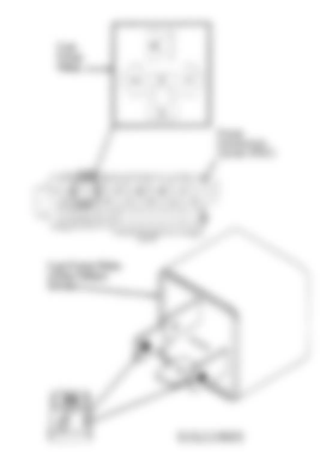
- Ensure ignition is OFF and disconnect DRB-II. Using a DVOM, check resistance of Pink wire (Black/Red wire on Wrangler) between engine controller terminal No. 25 and engine diagnostic connector. See Fig. 3 . If resistance is 10 ohms or more, repair open Pink wire (Black/Red wire on Wrangler).
- If resistance is less than 10 ohms, check resistance of Light Green wire (Black/Pink wire on Wrangler) between engine controller terminal No. 45 and engine diagnostic connector. If resistance is 10 ohms or more, repair open Light Green wire (Black/Pink wire on Wrangler).
- If resistance is less than 10 ohms, turn ignition off and disconnect DRB-II, DRB-II cartridge, and adapter cable. Find a second vehicle identical in equipment to vehicle being tested.
- Connect DRB-II to substitute (second) vehicle and use DRB-II as you did on original vehicle. If message screen is still blank, adapter cable or DRB-II (including cartridge) is faulty. Substitute adapter cable with a known good cable to find faulty component.
- If it is determined that adapter cable, DRB-II and cartridge are okay, replace engine controller. Reset EMR mileage and, on vehicles equipped with factory theft alarm, start vehicle at least 20 times to enable theft alarm system.
Jeep Comanche Eliminator 1992 - Other Error Messages
If BAD FRAMING, CARTRIDGE ERROR, LOW BATTERY, BAD OP CODE, HIGH BATTERY, RAM TEST FAILURE, COMMAND REJECTED or KEYPAD TEST FAILURE message is displayed, there is a DRB-II to vehicle communications system breakdown.
Fig. 3: Jeep Comanche Eliminator 1992 - Component Locations - Testing For NO RESPONSE Message
Jeep Comanche Eliminator 1992 - EMISSION MAINTENANCE REMINDER (EMR) MEMORY TEST
NOTE: Perform EMR memory test only if referred here by diagnostic tests.
- To perform EMR memory check, ensure ignition is off. Attach DRB-II to engine diagnostic connector. Connector is located on left side of engine compartment, near engine controller. See Fig. 2 . Turn ignition switch to RUN position.
- Copyright information and diagnostic program version will appear on screen for a few seconds. After a few seconds DRB-II menu will appear. At FUEL/IGN MENU, press "5" (ADJUSTMENTS) key. Press ENTER key. At ADJUSTMENTS menu, press "4" (EMR MEMORY CHK) key. Press ENTER key. The DRB-II display will read EMR MEMORY CHECK ARE YOU SURE? (ENTER TO CONTINUE).
- Press ENTER key. The DRB-II will display EMR MEMORY TEST WRITE TEST [-------] and after a few seconds IS INSTRUMENT PANEL MILEAGE BETWEEN XXXXX AND XXXXX? (PRESS YES OR NO). If vehicle mileage is within specification, EMR memory check is complete. Press YES key. If vehicle mileage is not within specification, go to next step.
- Press NO key. DRB-II will display ENTER MILEAGE SHOWN ON INSTRUMENT PANEL (USE ENTER TO END) XXXXXXX. Enter vehicle mileage. DO NOT enter tenths. When correct vehicle mileage is entered, press ENTER key.
- DRB-II will ask for verification of mileage entry. If mileage entry was accurate, press ENTER key. DRB-II will display EMR MEMORY CHECK COMPLETE. Vehicle must travel at least 8 miles for reset to occur.
Jeep Comanche Eliminator 1992 - EMISSION MAINTENANCE REMINDER (EMR) LIGHT RESET PROCEDURE
Emission Maintenance Reminder (EMR) light is designed to be a reminder to service vehicle emissions control system. It is not an emissions warning system, only a reminder to perform necessary emissions servicing.
Components to be serviced include PCV valve, oxygen sensor and some vacuum-operated components. EMR light will illuminate after a predetermined mileage.
- To reset EMR light, ensure ignition is off. Connect DRB-II to engine diagnostic connector. Connector is located on left side of engine compartment, near engine controller. See Fig. 2 . Turn ignition switch to RUN position.
- Copyright information and diagnostic program version will appear on screen for a few seconds. After a few seconds DRB-II menu will appear. At FUEL/IGN MENU, press "5" (ADJUSTMENTS) key. Press ENTER key.
- At ADJUSTMENTS menu, press "3" (RESET EMR LIGHT) key. Press ENTER key. Display will read RESET EMR LIGHT ARE YOUR SURE? (ENTER TO RESET). Press ENTER key.
Jeep Comanche Eliminator 1992 - EMISSION MAINTENANCE REMINDER (EMR) MILEAGE TRANSFER
NOTE: Perform mileage transfer procedure only if engine controller is being replaced.
- When engine controller is replaced, vehicle mileage must be copied from odometer to replacement engine controller memory. Transfer of vehicle mileage will enable new engine controller to operate EMR light properly.
- To transfer mileage to new engine controller, ensure ignition is off. Connect DRB-II to engine diagnostic connector. Connector is located on left side of engine compartment, near engine controller. See Fig. 2 . Turn ignition switch to RUN position.
- Copyright information and diagnostic program version will appear on screen for a few seconds. After a few seconds DRB-II menu will appear. At FUEL/IGN MENU, press "5" (ADJUSTMENTS) key. Press ENTER key. At ADJUSTMENTS menu, press "4" (EMR MEMORY CHK) key. Press ENTER key. The DRB-II display will read EMR MEMORY CHECK ARE YOU SURE? (ENTER TO CONTINUE).
- Press ENTER key. The DRB-II will display EMR MEMORY TEST WRITE TEST [-------] and after a few seconds IS INSTRUMENT PANEL MILEAGE BETWEEN XXXXX AND XXXXX? (PRESS YES OR NO). If vehicle mileage is within specification, EMR memory check is complete. Press YES key. If vehicle mileage is not within specification, go to next step.
- Press NO key. DRB-II will display ENTER MILEAGE SHOWN ON INSTRUMENT PANEL (USE ENTER TO END) XXXXXXX. Enter vehicle mileage. DO NOT enter tenths. When correct vehicle mileage is entered, press ENTER key.
- DRB-II will ask for verification of mileage entry. If mileage entry was accurate, press ENTER key. DRB-II will display EMR MEMORY CHECK COMPLETE. Vehicle must travel at least 8 miles for reset to occur.
Jeep Comanche Eliminator 1992 - THEFT ALARM SYSTEM
NOTE: If SECURITY light comes and remains on with ignition on, Chrysler Collision Detection (CCD) bus communication with engine controller has been lost. After servicing vehicle, ensure system operates properly. A malfunctioning theft alarm system may keep engine from starting.
Jeep Comanche Eliminator 1992 - SELF-DIAGNOSTIC TEST Cherokee
Turn ignition switch to ACCY position 3 times and leave in ACCY position to enter self-diagnostic mode. To stop self-diagnostic mode, return ignition switch to OFF position.
After entering self-diagnostic mode, the headlights, parking lights, and taillights will flash to verify theft alarm system operation. The horn should also sound twice.
While in self-diagnostic mode, it is recommended that illuminated entry module be removed. Otherwise its necessary to wait 30 seconds after opening or closing each door. Begin theft alarm system self-diagnosis as follows:
- Close ALL doors. Enter self-diagnostic mode and remove illuminated entry module. Module is located on a bracket behind instrument panel. Open and close each door and hood. The horn should sound when door jamb (hood) switch closes and again when switch opens. Wait one second before closing and opening doors (hood).
- Actuate power door locks and remote keyless entry (if equipped) in both the lock and unlock position. The horn should sound after each actuation. Rotate key in each door lock to the unlock position. The horn should sound when door jamb switch closes and again when switch opens. Wait one second before closing and opening doors.
- Place ignition switch in RUN position. Horn should sound to indicate proper operation of ignition input and exit theft alarm system self-diagnostic mode.
- If horn does not sound, it indicates a switch failure, an open/shorted circuit (lack of switch input), or a security alarm module failure. Check switch and wiring harness continuity. Service theft alarm system based on following self-diagnostics test results:
NOTE: A functional engine controller that has been used in a vehicle equipped with theft alarm system CANNOT be used in another vehicle that is NOT equipped with theft alarm system. If engine controller has been replaced, start vehicle at least 20 times to enable theft alarm system.
Jeep Comanche Eliminator 1992 - PARKING LIGHTS & TAILLIGHTS DO NOT FLASH Cherokee
- Turn ignition switch to RUN position and then OFF. Check for battery voltage at Pink/Light Green wire at terminal No. 21 of security alarm module. Security alarm module is located on driver's side of A/C-heater housing.
- If battery voltage is present, replace security alarm module and retest system. If battery voltage is NOT present, repair wiring harness and retest system.
Jeep Comanche Eliminator 1992 - ALL EXTERIOR LIGHTS DO NOT FLASH, BUT WORK NORMALLY Cherokee
- Turn ignition switch to RUN position and then OFF. Check if flash to pass switch operates properly (lightly pull and release turn signal lever). If flash to pass feature works properly (headlights come on and remain on until lever is release), go to next step. If flash to pass feature does not work properly, check for blown fuse. Replace fuse and retest system.
- Check for battery voltage at Pink/Light Green wire at terminal No. 21 of security alarm module. Security alarm module is located on driver's side of A/C-heater housing. If battery voltage is present, replace security alarm module and retest system. If battery voltage is NOT present, repair wiring harness and retest system.
Jeep Comanche Eliminator 1992 - HEADLIGHTS DO NOT FLASH, BUT WORK NORMALLY Cherokee
- Check (backprobe) for battery voltage at terminal No. 7 of security alarm module (Tan/Pink wire). Security alarm module is located on driver's side of A/C-heater housing. If battery voltage is present, go to next step. If battery voltage is NOT present, turn ignition switch to RUN position and then OFF. Replace security alarm module and retest system.
- Turn ignition switch to RUN position and then OFF. Disconnect security alarm module relay. Relay is taped to wiring harness, near driver's side kick panel. Check relay continuity between Black and Tan/Pink wire terminals. If continuity exists, go to next step. If no continuity exists, replace relay and retest system.
- Check continuity between relay connector and ground (Black wire). If no continuity exists, repair open Black (ground) wire and retest system. If continuity exists, check continuity of Tan/Pink wire between relay connector and terminal No. 7 of security alarm module. If no continuity exists, repair open Tan/Pink wire.
Jeep Comanche Eliminator 1992 - HORN DOES NOT SOUND TWICE Cherokee
Turn ignition switch to RUN position and then OFF. Check if horn operates normally. If horn does not operate, repair horn circuit. If horn operates normally, check continuity of Black/Red wire between horn and terminal No. 12 of security alarm module. Security alarm module is located on driver's side of A/C-heater housing. If continuity exists, replace security alarm module. If no continuity exists, repair open Black/Red (Gray/Orange) wire and retest system.
Jeep Comanche Eliminator 1992 - HORN SOUNDS TWICE AND HEADLIGHTS, PARKING & TAIL LIGHTS FLASH Cherokee
- Ensure that doors, liftgate, and hood are closed. Verify SECURITY light is flashing. If SECURITY light is not flashing, check bulb and wiring harness. Repair or replace as necessary. If bulb and wiring are okay, replace security alarm module and retest system.
- If SECURITY light is flashing, turn ignition switch to OFF position. Remove illuminated entry module from vehicle. Module is located on a bracket behind instrument panel.
- Check theft alarm switches by opening and closing doors and liftgate. Horn should sound one time, at each switch, to ensure proper operation. Replace switch(es) or repair wiring harness as necessary. If switches are okay, check hood switch by opening and closing hood.
- Replace hood switch or repair wiring harness as necessary. If hood switch is okay, unlock (with key) each front door and liftgate one at a time to test disarm switches. Replace switch(es) or repair wiring harness as necessary and retest system.
- If disarm switches are okay, cycle power door locks to lock and then unlock position. Replace door lock switch(es), lock/unlock relay(s), or repair wiring harness as necessary and retest system.
- If power door locks operate properly, lock and unlock vehicle with keyless entry transmitter. Replace keyless entry transmitter, receiver, or repair wiring harness as necessary and retest system.
- If keyless entry system operates properly, turn ignition switch to ON position and wait 30 seconds. If SECURITY light comes on and stays on, repair or replace CCD bus and wiring as necessary and retest system. If SECURITY light remains off, theft alarm system is operating properly. Reconnect illuminated entry module
Jeep Comanche Eliminator 1992 - SUMMARY
If no hard fault codes or only pass codes are present, driveability symptoms exist or intermittent codes exist, proceed to the TESTS W/O CODES article in this section for diagnosis by symptom (i.e. ROUGH IDLE, NO START, etc.) or intermittent diagnostic procedures.
Jeep Comanche Eliminator 1992 - CONNECTOR IDENTIFICATION
Jeep Comanche Eliminator 1992 CONNECTOR IDENTIFICATION DIRECTORY
Connector See
Fig. Automatic Idle Speed (AIS) Motor Fig. 4 Charge & Coolant Temperature Sensor Fig. 5 Crankshaft Position Sensor Fig. 6 Distance Sensor Except Wrangler Fig. 7 Wrangler Fig. 8 Distributor Sync Pick-Up Sensor Fig. 9 Engine Controller Fig. 10 Engine Diagnostic Fig. 11 Fuel Injector Fig. 12 Ignition Coil Fig. 13 Manifold Absolute Pressure (MAP) Sensor Fig. 14 Oxygen (O2) Sensor Fig. 15 Relays Fig. 16 Throttle Position Sensor Fig. 17


Jeep Comanche Eliminator 1992 ENGINE DIAGNOSTIC CONNECTOR TERMINAL IDENTIFICATION
Cavity & Model Wire Color No. 1 Cherokee & Comanche Black Wrangler Black/Yellow No. 2 Not Used No. 3 Cherokee & Comanche Pink Wrangler Black/Red No. 4 Cherokee & Comanche Light Green Wrangler Black/Pink No. 5 Cherokee & Comanche Dark Blue/White Wrangler white/Yellow No. 6 Not Used
Fig. 12: Jeep Comanche Eliminator 1992 - Component Locations - Fuel Injector Connector Terminal ID

Fig. 13: Jeep Comanche Eliminator 1992 - Component Locations - Ignition Coil Connector Terminal ID

Fig. 14: Jeep Comanche Eliminator 1992 - Component Locations - MAP Sensor Connector Terminal ID


Fig. 16: Jeep Comanche Eliminator 1992 - Component Locations - Relay Connector Terminal ID


Fig. 18: Jeep Comanche Eliminator 1992 - Component Locations - Testing Fuel Pump Relay
Jeep Comanche Eliminator 1992 - SELF-DIAGNOSTIC TESTS - PRELIMINARY INFORMATION
CAUTION: When battery is disconnected, vehicle computer and energy systems may lose memory data. Driveability problems may exist until computer systems have completed a relearn cycle. See COMPUTER RELEARN PROCEDURES article in the GENERAL INFORMATION section before disconnecting battery.
Jeep Comanche Eliminator 1992 - NO-START TESTS TEST NS-1A - QUALIFYING NO START CONDITION
NOTE: For connector terminal identification, see CONNECTOR IDENTIFICATION . For wiring diagram, see WIRING DIAGRAMS at end of article.
- Perform visual inspection of vehicle. See VISUAL INSPECTION under SELF-DIAGNOSTIC SYSTEM. Ensure battery is fully charged. Using DRB-II, erase faults and reset adaptive memory. Try to start engine by cranking for at least 10 seconds. Ensure key is turned off before each attempt to start engine. Turn ignition on. Using DRB-II, read faults.
- If DRB-II displays a fault message, perform appropriate test. See DRB-II FAULT MESSAGES - NO START CODES table. If DRB-II does not display any fault message, go to step 3).
Jeep Comanche Eliminator 1992 DRB-II FAULT MESSAGES - NO START CODES
DTC DRB-II Message Test No. Code 25 AUTOMATIC IDLE SPEED MOTOR CIRCUITS NS-6A Code 42 AUTO SHUTDOWN RELAY CONTROL CIRCUIT NS-10A Code 22 & 24 COOLANT VOLTAGE & TPS VOLTAGE HIGH (1) Code 27 INJECTOR CONTROL CIRCUIT FAULT NS-5A Code 53 INTERNAL CONTROLLER FAILURE (2) Code 53 CONTROLLER FAILURE SPI COMMUNICATIONS (2) Code 42 NO ASD RELAY VOLTAGE SENSE AT CONTROLLER NS-11A Code 42 NO REFERENCE SIGNAL DURING CRANKING NS-9A NO RESPONSE NS-8A Code 54 NO SYNC PICK-UP SIGNAL NS-9B (1) Repair open Black/Light Blue wire (Brown/Red wire on Wrangler) to engine controller terminal No. 4. (2) Replace engine controller. Perform VERIFICATION TEST VER-1 . - Try to start engine by cranking for at least 10 seconds. Ensure key is turned off before each attempt to start engine. If engine starts and stalls, perform TEST NS-2A. If engine does not start and stall, turn ignition off. Disconnect any spark plug wire from spark plug.
- Insert an insulated screwdriver in cable terminal. Hold screwdriver a maximum of 1/4" away from a good ground. Watch for spark while cranking engine for 10 seconds. Consider 1-2 sparks as a no-spark condition. If a good spark occurs, perform TEST NS-2A.
- If a good spark does not occur, turn ignition off. Disconnect coil secondary wire from distributor. Hold coil wire a maximum of 1/4" away from a good ground. Watch for spark while cranking engine for 10 seconds. If there is good spark, repair secondary ignition system (distributor cap, rotor or spark plug wires). Perform VERIFICATION TEST VER-1 .
- If a good spark does not occur, turn ignition off. Remove coil secondary wire. Using a DVOM, measure coil secondary wire resistance. If resistance is greater than 15,000 ohms, replace coil secondary wire. Perform VERIFICATION TEST VER-1 . If resistance is 15,000 ohms or less, remove distributor cap. Watch for rotor to turn while cranking engine. If rotor does not turn, repair distributor drive system. Perform VERIFICATION TEST VER-1 .
- If rotor turned, reinstall distributor cap. Disconnect ignition coil connector. Using DRB-II, actuate fuel system. With fuel system actuating, place DRB-II in voltmeter mode. Probe Dark Green/Orange wire (Dark Green/Black wire on Wrangler) in ignition coil harness connector. If voltage is not greater than 10 volts, repair Dark Green/Orange (Dark Green/Black) wire between coil and ASD relay splice. Perform VERIFICATION TEST VER-1 .
- If voltage is 10 volts or more, probe Gray wire (Yellow/Black wire on Wrangler) in ignition coil harness connector. If voltage is greater than 10 volts, go to step 11). If voltage is 10 volts or less, turn ignition off. Disconnect engine controller connector. Place DRB-II in ohmmeter mode. Probe Gray wire (Yellow/Black wire on Wrangler) in engine controller connector terminal No. 19.
- If resistance is less than 10 ohms, repair Gray wire (Yellow/Black wire on Wrangler) for a short to ground. Perform VERIFICATION TEST VER-1 . If resistance is 10 ohms or more, check resistance of Gray wire (Yellow/Black wire on Wrangler) between coil harness connector and engine controller connector terminal No. 19.
- If resistance is greater than 10 ohms, repair open Gray wire (Yellow/Black wire on Wrangler). Perform VERIFICATION TEST VER-1 . If resistance is 10 ohms or less, replace engine controller. Perform VERIFICATION TEST VER-1 .
- Turn ignition off. Using a DVOM, check ignition coil primary circuit resistance. If resistance is not .8-1.3 ohms at 75?F (24?C), replace ignition coil. Perform VERIFICATION TEST VER-1 .
- If resistance is .8-1.3 ohms at 75?F (24?C), check ignition coil secondary circuit resistance (coil - terminal and coil tower). If resistance is not 10,000-16,000 ohms, replace ignition coil. Perform VERIFICATION TEST VER-1 . If resistance is 10,000-16,000 ohms, reconnect ignition coil connector. Perform TEST NS-9A.
Jeep Comanche Eliminator 1992 - TEST NS-2A - INSPECTING FUEL SYSTEM
NOTE: For connector terminal identification, see CONNECTOR IDENTIFICATION . For wiring diagram, see WIRING DIAGRAMS . If vehicle is equipped with factory theft alarm, use DRB-II to read theft alarm status. If DRB-II displays FUEL ON, go to step 1). If not, check theft alarm system. See THEFT ALARM SYSTEM at beginning of this article.
- Ensure throttle is at idle position. Using DRB-II, read TPS sensor voltage. If voltage is more than 1.5 volts, replace throttle position sensor. Perform VERIFICATION TEST VER-1 . If voltage is 1.5 volts or less, disconnect fuel injector No. 1 connector.
- Place DRB-II in voltmeter mode and actuate ASD fuel system. Probe Dark Green/Orange wire (Dark Green/Black wire on Wrangler). If voltage is 10 volts or less on both wires, repair Dark Green/Orange between injector connector and harness splice. Perform VERIFICATION TEST VER-1 . If voltage is more than 10 volts on both wires, turn ignition off.
WARNING: Fuel system must be opened and may be under high pressure. - Install fuel pressure gauge in fuel supply line, on fuel rail near fuel pressure regulator. Ensure fuel tank is at least 1/4 full. Reconnect injector connector. Turn ignition on. Using DRB-II, actuate ASD fuel system. Listen for fuel pump operation at fuel tank. If fuel pump operation cannot be heard, go to TEST NS-7A.
- If fuel pump operation can be heard, read fuel pressure gauge. If fuel pressure is more than 43 psi, perform TEST NS-4B. If fuel pressure is less than 35 psi, perform TEST NS-4A . If fuel pressure is not less than 35 or more than 43 and vehicle starts/stalls repeatedly, perform TEST NS-12A. If vehicle does not start and stall repeatedly, perform TEST NS-3A.
Jeep Comanche Eliminator 1992 - TEST NS-3A - INSPECTING MECHANICAL SYSTEM
NOTE: For connector terminal identification, see CONNECTOR IDENTIFICATION . For wiring diagram, see WIRING DIAGRAMS at end of article.
- Turn ignition off. Check spark plug wires for proper firing order. If firing order is not correct, reconnect wires in correct firing order. Perform VERIFICATION TEST VER-1 . If firing order is correct, remove all spark plugs and inspect tips for fuel (flooding). Clean spark plugs as necessary. Reinstall spark plugs. Connect timing light to engine.
- Check ignition timing while cranking engine. If ignition timing is 0-25 degrees BTDC, go to step 3). If timing is not 0-25 degrees BTDC, replace engine controller. Perform VERIFICATION TEST VER-1 .
- Locate cylinder No. 1 on distributor cap and mark housing for reference. Position piston in cylinder No. 1 to Top Dead Center (TDC) of compression stroke. Remove distributor cap and check if rotor is pointing to mark on distributor housing. Reposition distributor housing into correct alignment, if necessary, and go to next step.
- Turn ignition off. Disconnect engine controller connector and MAP sensor connector. Using a DVOM, check resistance of Violet/White wire (Brown/Yellow wire on Wrangler) between MAP sensor and engine controller connectors.
- If resistance is 10 ohms or more, repair open Violet/White wire (Brown/Yellow wire on Wrangler). Perform VERIFICATION TEST VER-1 . If resistance is less than 10 ohms, check valve timing and engine compression. If valve timing and engine compression are okay, replace MAP sensor. Perform VERIFICATION TEST VER-1 . If valve timing and engine compression are not okay, repair engine as necessary. Perform VERIFICATION TEST VER-1 .
Jeep Comanche Eliminator 1992 - TEST NS-4A - CORRECTING FUEL DELIVERY
WARNING: Fuel system must be opened and may be under high pressure.
- Measure and record fuel pressure gauge reading at fuel rail. Turn ignition off. Remove fuel pressure gauge and reconnect fuel line. Install fuel pressure gauge in fuel line between fuel tank and fuel filter. Turn ignition on. Using DRB-II, actuate ASD fuel system. Record fuel pressure gauge reading.
- Compare fuel pressure gauge readings. If fuel pressure is not at least 10 psi more, go to step 3). If fuel pressure is at least 10 psi more, go to step 4).
CAUTION: DO NOT allow fuel pressure to exceed 70 psi. - Watch fuel pressure gauge while gently squeezing fuel return hose. If fuel pressure is greater than 35 psi, replace fuel pressure regulator. Perform VERIFICATION TEST VER-1 . If fuel pressure is 35 psi or less, replace fuel pump and filter sock assembly. Perform VERIFICATION TEST VER-1 .
- Inspect fuel lines between fuel filter and fuel rail for restriction. If fuel lines are restricted, repair lines as necessary. Perform VERIFICATION TEST VER-1 . If lines are not restricted, replace fuel filter. Perform VERIFICATION TEST VER-1 .
Jeep Comanche Eliminator 1992 - TEST NS-4B - CORRECTING FUEL DELIVERY
WARNING: Fuel system must be opened and may be under high pressure.
- Ensure fuel tank is at least 1/4 full. Relieve fuel system pressure. Remove fuel return hose from fuel rail. Connect a 6 foot long piece of fuel hose to fuel rail return fitting. Place other end of hose into an approved gasoline container (minimum 2 gallon capacity). Turn ignition on. Using DRB-II, actuate ASD fuel system.
- Read fuel pressure gauge. If fuel pressure is 43 psi or more, replace fuel pressure regulator. Perform VERIFICATION TEST VER-1 . If fuel pressure is less than 43 psi, turn ignition off. Reconnect fuel return hose. Disconnect fuel return hose from fuel tank. Connect 6 foot long piece of fuel hose to disconnected fuel return hose. Place other end of fuel hose into an approved gasoline container (minimum 2 gallon capacity).
- Turn ignition on. Using DRB-II, actuate ASD fuel system. Read fuel pressure gauge. If fuel pressure is less than 43 psi, replace fuel return assembly in fuel tank. Perform VERIFICATION TEST VER-1 . If fuel pressure is 43 psi or more, repair restricted fuel return line between fuel rail and fuel tank. Perform VERIFICATION TEST VER-1 .
Jeep Comanche Eliminator 1992 - TEST NS-5A, "FUEL INJECTOR CONTROL CIRCUIT"
NOTE: For connector terminal identification, see CONNECTOR IDENTIFICATION . For wiring diagram, see WIRING DIAGRAMS at end of article.
- Turn ignition off. Disconnect fuel injector No. 1 connector. Turn ignition on. Using DRB-II, actuate ASD fuel system. Place DRB-II in voltmeter mode. Probe Dark Green/Orange wire (Dark Green/Black on Wrangler) in injector harness connector.
- If voltage is less than 10 volts, repair open Dark Green/Orange wire (Dark Green/Black wire on Wrangler). Perform VERIFICATION TEST VER-1 . If voltage is 10 volts or more, replace engine controller. Perform VERIFICATION TEST VER-1 .
Jeep Comanche Eliminator 1992 - TEST NS-6A - REPAIRING FAULT "AUTO IDLE SPEED MOTOR CIRCUIT"
NOTE: For connector terminal identification, see CONNECTOR IDENTIFICATION . For wiring diagram, see WIRING DIAGRAMS at end of article.
- Disconnect Automatic Idle Speed (AIS) motor connector. Turn ignition on. Using DRB-II, actuate AIS motor. Place DRB-II in voltmeter mode. Probe Gray/Red wire (Dark Green/Black wire on Wrangler) in AIS motor harness connector. When normal, voltage will switch from less than one volt to more than 10 volts.
- If voltage stayed less than one volt, repair Gray/Red wire (Dark Green/Black wire on Wrangler) for a short to ground. Perform VERIFICATION TEST VER-1 . If voltage stayed more than 10 volts, repair Gray/Red wire (Dark Green/Black wire on Wrangler) for a short to voltage. Perform VERIFICATION TEST VER-1 .
- If voltage did NOT stay less than one volt or more than 10 volts, probe Yellow/Black wire (Pink/Black wire on Wrangler) in AIS motor harness connector.
- If voltage stayed less than one volt, repair Yellow/Black wire (Pink/Black wire on Wrangler) for a short to ground. Perform VERIFICATION TEST VER-1 . If voltage stayed more than 10 volts, repair Yellow/Black wire (Pink/Black wire on Wrangler) for a short to voltage. Perform VERIFICATION TEST VER-1 .
- If voltage did NOT stay less than one volt or more than 10 volts, probe Brown/White wire (Red/Yellow wire on Wrangler) in AIS motor harness connector. If voltage stayed less than one volt, repair Brown/White wire (Red/Yellow wire on Wrangler) for a short to ground. Perform VERIFICATION TEST VER-1 . If voltage stayed more than 10 volts, repair Brown/White wire (Red/Yellow wire on Wrangler) for a short to voltage. Perform VERIFICATION TEST VER-1 .
- If voltage did NOT stay less than one volt or more than 10 volts, probe Violet/Black wire (Dark Blue/Yellow wire on Wrangler) in AIS motor harness connector. If voltage stayed less than one volt, repair Violet/Black wire (Dark Blue/Yellow wire on Wrangler) for a short to ground. Perform VERIFICATION TEST VER-1 .
- If voltage stayed more than 10 volts, repair Violet/Black wire (Dark Blue/Yellow wire on Wrangler) for a short to voltage. Perform VERIFICATION TEST VER-1 . If voltage did NOT stay less than one volt or more than 10 volts, turn ignition off. Reconnect AIS motor. Disconnect engine controller 60-pin connector.
- Using a DVOM, measure resistance between engine controller connector terminals No. 39 and 59. If resistance is less than 35 ohms, replace AIS motor. Perform VERIFICATION TEST VER-1 . If resistance is 35 ohms or more, go to next step.
- Using a DVOM, measure resistance between engine controller connector terminals No. 40 and 60. If resistance is less than 35 ohms, replace AIS motor. Perform VERIFICATION TEST VER-1 . If resistance is 35 ohms or more, go to next step.
- Using a DVOM, measure resistance between engine controller connector terminals No. 39 and 60. If resistance measures less than 10 ohms, repair wires (terminals No. 1 and 2 of the AIS harness connector) for a short to each other. See Fig. 4 . Perform VERIFICATION TEST VER-1 .
- If resistance in step 10) was 10 ohms or more, check if resistance is less than 75 ohms (between terminals No. 39 and 60). If resistance is less than 75 ohms, go next step. If resistance is 75 ohms or more, go to step 13).
- Using a DVOM, measure resistance between engine controller connector terminals No. 59 and 60. If resistance is less than 10 ohms, repair wires (terminals No. 2 and 4 of AIS harness connector) for a short to each other. Perform VERIFICATION TEST VER-1 . If resistance is 10 ohms or more, repair wires (terminals No. 1 and 3 of AIS harness connector) for a short to each other. Perform VERIFICATION TEST VER-1 .
- If resistance in step 11) was 75 ohms or more, check if resistance is less than 120 ohms (between terminals No. 39 and 60). If resistance is less than 120 ohms, repair wires (terminals No. 3 and 4 of AIS harness connector) for a short to each other. Perform VERIFICATION TEST VER-1 . If resistance is 120 ohms or more, replace engine controller. Perform VERIFICATION TEST VER-1 .
Jeep Comanche Eliminator 1992 - TEST NS-7A - INSPECTING FUEL PUMP
NOTE: For connector terminal identification, see CONNECTOR IDENTIFICATION . For wiring diagram, see WIRING DIAGRAMS at end of article.
- Using DRB-II, stop actuation test. Using DRB-II, actuate ASD relay. Touch fuel pump relay to check for operation. If fuel pump relay does not pulsate, perform TEST NS-7B . If fuel pump relay pulsates, stop actuation test. Disconnect fuel pump relay. Turn ignition on. Place DRB-II in voltmeter mode. Probe Red wire (Pink/Yellow wire on Wrangler) in fuel pump relay connector.
- If voltage is 10 volts or less, repair Red wire (Pink/Yellow wire on Wrangler) for an open circuit to splice. Perform VERIFICATION TEST VER-1 . If voltage is greater than 10 volts, disconnect fuel pump harness connector. Reconnect fuel pump relay. Using DRB-II, actuate fuel system. Place DRB-II in voltmeter mode. Probe Dark Green/Red wire (Orange/Black wire on Wrangler) in fuel pump connector. If voltage is more than 10 volts, go to step 6).
- If voltage is 10 volts or less, turn ignition off. Disconnect fuel pump relay. Using a DVOM, check resistance between fuel pump relay connector Dark Green/Black wire (Orange/Black on Wrangler) and fuel pump connector Dark Green/Red wire (Orange/Black on Wrangler).
- If resistance is less than 10 ohms, replace fuel pump relay. Perform VERIFICATION TEST VER-1 . If resistance is 10 ohms or more (Cherokee or Comanche), go to next step. If resistance is 10 ohms or more, repair open between fuel pump relay connector Orange/Dark Blue wire (Orange/Black on Wrangler) and fuel pump connector Orange/Black wire. Perform VERIFICATION TEST VER-1 .
- Disconnect ballast resistor. Ballast resistor is located next to windshield washer fluid reservoir. Using a DVOM, measure resistance across ballast resistor. If resistance is 10 ohms or more, replace ballast resistor. Perform VERIFICATION TEST VER-1 . If resistance is less than 10 ohms, repair Dark Green/Black wire between fuel pump relay and fuel pump. Perform VERIFICATION TEST VER-1 .
- Using DRB-II, stop actuation test. Place DRB-II in ohmmeter mode. Probe Black wire (Tan/Black wire on Wrangler) in fuel pump connector. If resistance is less than 5 ohms, replace fuel pump. Perform VERIFICATION TEST VER-1 . If resistance is 5 ohms or more, repair Black wire (Tan/Black wire on Wrangler) wire for an open circuit to ground. Perform VERIFICATION TEST VER-1 .
Jeep Comanche Eliminator 1992 - TEST NS-7B - INSPECTING FUEL PUMP
NOTE: For connector terminal identification, see CONNECTOR IDENTIFICATION . For wiring diagram, see WIRING DIAGRAMS at end of article.
- Turn ignition off. Disconnect fuel pump relay. Turn ignition on. Probe Dark Blue wire (White/Yellow wire on Wrangler) in fuel pump relay connector. If voltage is 10 volts or less, repair Dark Blue wire (White/Yellow wire on Wrangler) for an open circuit to splice. Perform VERIFICATION TEST VER-1 .
- If voltage is more than 10 volts, measure resistance across fuel pump relay terminals "A" and "C". See Fig. 18 . If resistance is 100 ohms or more, replace fuel pump relay. Perform VERIFICATION TEST VER-1 . If resistance is less than 100 ohms, repair open Dark Blue/Yellow wire (Orange/Dark Green wire on Wrangler) between fuel pump relay connector and splice. Perform VERIFICATION TEST VER-1 .
Jeep Comanche Eliminator 1992 - TEST NS-8A - "NO RESPONSE" CONDITION
NOTE: For connector terminal identification, see CONNECTOR IDENTIFICATION . For wiring diagram, see WIRING DIAGRAMS at end of article.
- Turn ignition off. Disconnect Throttle Position Sensor (TPS). Turn ignition on. Place DRB-II in voltmeter mode. Probe Violet/White wire (Brown/Yellow wire on Wrangler) at TPS harness connector. If voltage measures more than 6 volts, repair open at engine controller connector terminals No. 5, 11 and 12. Perform VERIFICATION TEST VER-1 .
- If voltage is 6 volts or less, check if voltage is less than 4.4 volts. If voltage is 4.4 volts or less, go to next step. If voltage is more than 4.4 volts, reconnect TPS connector. Disconnect MAP sensor connector. Probe Violet/White wire (Brown/Yellow wire on Wrangler) at MAP sensor connector. If voltage is more than 4.4 volts, see NO RESPONSE MESSAGE under DRB-II PROBLEMS & ERROR MESSAGES under SELF-DIAGNOSTIC SYSTEM. If voltage is 4.4 volts or less, replace TPS. Perform VERIFICATION TEST VER-1 .
- Disconnect MAP sensor connector. Probe Violet/White wire (Brown/Yellow wire on Wrangler) at TPS connector. If voltage is more than 4.4 volts, replace MAP sensor. Perform VERIFICATION TEST VER-1 . If voltage is 4.4 volts or less, turn ignition off. Disconnect and inspect engine controller connector. Repair connector as necessary and go to next step.
- Place DRB-II in ohmmeter mode. Probe engine controller connector terminal No. 6 Violet/White wire (Brown/Yellow wire on Wrangler). If resistance is less than 10 ohms, repair short to ground in Violet/White (Brown/Yellow) wire. Perform VERIFICATION TEST VER-1 .
- If resistance is 10 ohms or more, turn ignition on. Place DRB-II in voltmeter mode. Probe engine controller connector terminal No. 9 Dark Blue wire (White/Yellow wire on Wrangler). If voltage is 10 volts or less, repair open Dark Blue (Light Blue/Red; White/Yellow) wire between engine controller connector terminal No. 9 and ignition switch. Perform VERIFICATION TEST VER-1 .
- If voltage is more than 10 volts, probe engine controller connector terminal No. 3 Red wire (Pink/Yellow wire on Wrangler). If voltage is more than 10 volts, replace engine controller. Perform VERIFICATION TEST VER-1 . If voltage is 10 volts or less, go to next step.
- Turn ignition off. Place DRB-II in ohmmeter mode. Probe engine controller connector terminal No. 3 Red wire (Pink/Yellow wire on Wrangler). If resistance is less than 10 ohms, repair Red (Pink/Yellow) wire for a short to ground between battery and engine controller connector terminal No. 3.
- If resistance is 10 ohms or more, inspect fuse and fused circuit between battery and engine controller connector terminal No. 3. If fuse is okay, repair open repair Red wire (Pink/Yellow wire on Wrangler) between battery and engine controller connector terminal No. 3. If fuse is NOT okay, go to next step.
- Disconnect Auto Shutdown (ASD) relay. Place DRB-II in ohmmeter mode. Probe Dark Green/Orange wire (Dark Green/Black wire on Wrangler) in ASD relay connector. If resistance is 10 ohms or less, go to step 12).
- If resistance is more than 10 ohms, reconnect ASD relay. Disconnect fuel pump relay, fuel pump connector, and oxygen sensor connector. Probe Dark Green/Black wire (Orange/Black wire on Wrangler) in fuel pump relay connector. If resistance is less than 10 ohms, repair short to ground in Dark Green/Black wire (Orange/Black wire on Wrangler).
- If resistance is 10 ohms or more, probe both White wires at oxygen sensor connector. If resistance for either wire is 10 ohms or more, replace fuel pump. Perform VERIFICATION TEST VER-1 . If resistance for either wire is less than 10 ohms, replace oxygen sensor. Perform VERIFICATION TEST VER-1 .
- Disconnect ignition coil connector. If resistance is more than 10 ohms, replace ignition coil. Perform VERIFICATION TEST VER-1 . If resistance is 10 ohms or less, go to next step.
- Disconnect fuel injector No. 1 connector. If resistance is more than 10 ohms, replace fuel injector No. 1. Perform VERIFICATION TEST VER-1 . If resistance is 10 ohms or less, go to next step.
- Disconnect fuel injector No. 2 connector. If resistance is more than 10 ohms, replace fuel injector No. 2. Perform VERIFICATION TEST VER-1 . If resistance is 10 ohms or less, go to next step.
- Disconnect fuel injector No. 3 connector. If resistance is more than 10 ohms, replace fuel injector No. 3. Perform VERIFICATION TEST VER-1 . If resistance is 10 ohms or less, go to next step.
- Disconnect fuel injector No. 4 connector. If resistance is more than 10 ohms, replace fuel injector No. 4. Perform VERIFICATION TEST VER-1 . If resistance is 10 ohms or less (4-cylinder engine), go step 19). If resistance is 10 ohms or less (6-cylinder engine), go to next step.
- Disconnect fuel injector No. 5 connector. If resistance is more than 10 ohms, replace fuel injector No. 5. Perform VERIFICATION TEST VER-1 . If resistance is 10 ohms or less, go to next step.
- Disconnect fuel injector No. 6 connector. If resistance is more than 10 ohms, replace fuel injector No. 6. Perform VERIFICATION TEST VER-1 . If resistance is 10 ohms or less, go to next step.
- Disconnect alternator. Probe Dark Green/Orange wire (Dark Green/Black wire on Wrangler) in ASD relay connector. If resistance is more than 10 ohms, replace alternator. Perform VERIFICATION TEST VER-1 . If resistance is 10 ohms or less, repair Dark Green/Orange wire (Dark Green/Black wire on Wrangler) for a short to ground. Perform VERIFICATION TEST VER-1 .
Jeep Comanche Eliminator 1992 - TEST NS-9A - "NO REFERENCE SIGNAL DURING CRANKING"
NOTE: For connector terminal identification, see CONNECTOR IDENTIFICATION . For wiring diagram, see WIRING DIAGRAMS at end of article.
- Disconnect crank position sensor. Turn ignition on. Place DRB-II in voltmeter mode. Probe Gray/Black wire (Red/Dark Green wire on Wrangler) in crank position sensor connector. If voltage is greater than 4.5 volts, go to step 4). If voltage is 4.5 volts or less, turn ignition off. Disconnect engine controller 60-pin connector.
- Place DRB-II in ohmmeter mode. Probe Gray/Black wire (Red/Dark Green wire on Wrangler) in crank position sensor connector. If resistance is less than 10 ohms, repair Gray/Black wire (Red/Dark Green wire on Wrangler) for a short to ground. Perform VERIFICATION TEST VER-1 . If resistance is 10 ohms or more, go to next step.
- Using a DVOM, check continuity of Gray/Black wire (Red/Dark Green wire on Wrangler) between engine controller connector terminal No. 24 and crank position sensor connector. If resistance measures less than 10 ohms, replace engine controller. Perform VERIFICATION TEST VER-1 . If resistance is 10 ohms or more, repair open Gray/Black wire (Red/Dark Green wire on Wrangler). Perform VERIFICATION TEST VER-1 .
- Probe Orange wire (White/Black wire on Wrangler) in crank position sensor connector. If voltage is 7.5 volts or less (except Wrangler), go to step 6). If voltage is 7.5 volts or less (Wrangler), go to step 8). If voltage is greater than 7.5 volts (all models), go to next step.
- Turn ignition off. Probe Black/Light Blue wire (Brown/Red wire on Wrangler) in crank position sensor connector. If resistance measures less than 10 ohms, replace crank position sensor. Perform VERIFICATION TEST VER-1 . If resistance is 10 ohms or more, repair open Black/Light Blue wire (Brown/Red wire on Wrangler) between engine controller connector terminal No. 4 and crank position sensor connector. Perform VERIFICATION TEST VER-1 .
- Turn ignition off. Disconnect engine controller 60-pin connector. Place DRB-II in ohmmeter mode. Probe engine controller connector terminal No. 7 (Orange wire). If resistance is less than 10 ohms, repair Orange wire for a short to ground. Disconnect battery quick disconnect. Reconnect battery quick disconnect. Perform VERIFICATION TEST VER-1 .
- If resistance is 10 ohms or more, check Orange wire for continuity between engine controller connector terminal No. 7 and crank position sensor connector using a DVOM. If resistance is less than 10 ohms, replace engine controller. Perform VERIFICATION TEST VER-1 . If resistance is 10 ohms or more, repair Orange wire between engine controller connector terminal No. 7 and crank position sensor connector. Perform VERIFICATION TEST VER-1 .
- Disconnect distance (speed) sensor. Place DRB-II in voltmeter mode. Probe White/Black wire in crank position sensor connector. If voltage is greater than 7.5 volts, replace distance (speed) sensor. Perform VERIFICATION TEST VER-1 . If voltage is 7.5 volts or less, go to next step.
- Turn ignition off. Disconnect engine controller 60-pin connector. Place DRB-II in ohmmeter mode. Probe engine controller connector terminal No. 7 (White/Black wire). If resistance is less than 10 ohms, repair White/Black wire for a short to ground. Disconnect battery quick disconnect. Reconnect battery quick disconnect. Perform VERIFICATION TEST VER-1 .
- If resistance is 10 ohms or more, check White/Black wire for continuity between engine controller connector terminal No. 7 and distributor sync pick-up sensor connector using a DVOM. If resistance is less than 10 ohms, replace engine controller. Perform VERIFICATION TEST VER-1 . If resistance is 10 ohms or more, repair White/Black wire between engine controller connector terminal No. 7 and sync sensor connector. Perform VERIFICATION TEST VER-1 .
Jeep Comanche Eliminator 1992 - TEST NS-9B - "NO SYNC PICK-UP SIGNAL"
NOTE: For connector terminal identification, see CONNECTOR IDENTIFICATION . For wiring diagram, see WIRING DIAGRAMS at end of article.
- Ensure distributor shaft turns when engine is cranked. If shaft does not turn, repair as necessary. Perform VERIFICATION TEST VER-1 . If shaft turns, disconnect distributor sync pick-up sensor. Turn ignition on. Place DRB-II in voltmeter mode. Probe Tan/Yellow wire (Gray/Black wire on Wrangler) in distributor sync pick-up connector. If voltage is more than 4.5 volts, go to step 4).
- If voltage is 4.5 volts or less, turn ignition off. Disconnect engine controller 60-pin connector. Place DRB-II in ohmmeter mode. Probe Tan/Yellow wire (Gray/Black wire on Wrangler) in distributor sync pick-up connector. If resistance is less than 10 ohms, repair Tan/Yellow wire (Gray/Black wire on Wrangler) for a short to ground. Perform VERIFICATION TEST VER-1 .
- If resistance is 10 ohms or more, check Tan/Yellow wire (Gray/Black wire on Wrangler) for continuity between engine controller connector terminal No. 44 and distributor sync pick-up sensor connector using a DVOM. If resistance is less than 10 ohms, replace engine controller. Perform VERIFICATION TEST VER-1 . If resistance is 10 ohms or more, repair open Tan/Yellow wire (Gray/Black wire on Wrangler). Perform VERIFICATION TEST VER-1 .
- Probe Orange wire (White/Black wire on Wrangler) in distributor sync pick-up connector. If voltage is 7.5 volts or less (except Wrangler), go to step 6). If voltage is 7.5 volts or less (Wrangler), go to step 8). If voltage is greater than 7.5 volts (all models), go to next step.
- Turn ignition off. Place DRB-II in ohmmeter mode. Probe Black/Light Blue wire (Brown/Red wire on Wrangler) in distributor sync pick-up connector. If resistance is less than 10 ohms, replace distributor sync pick-up. Perform VERIFICATION TEST VER-1 . If resistance is 10 ohms or more, repair open Black/Light Blue wire (Brown/Red on Wrangler) between sensor connector and splice. Perform VERIFICATION TEST VER-1 .
- Turn ignition off. Disconnect engine controller 60-pin connector. Place DRB-II in ohmmeter mode. Probe engine controller connector terminal No. 7 Orange wire. If resistance is less than 10 ohms, repair Orange wire for a short to ground. Disconnect battery quick disconnect. Reconnect battery quick disconnect. Perform VERIFICATION TEST VER-1 .
- If resistance is 10 ohms or more, check Orange wire for continuity between engine controller connector terminal No. 7 and distributor sync pick-up sensor connector using a DVOM. If resistance measures less than 10 ohms, replace engine controller. Perform VERIFICATION TEST VER-1 . If resistance is 10 ohms or more, repair Orange wire between engine controller connector terminal No. 7 and distributor sync pick-up sensor connector. Perform VERIFICATION TEST VER-1 .
- Disconnect distance (speed) sensor. Place DRB-II in voltmeter mode. Probe Orange wire in distributor sync pick-up sensor connector. If voltage is greater than 7.5 volts, replace distance (speed) sensor. Perform VERIFICATION TEST VER-1 . If voltage is 7.5 volts or less, go to next step.
- Turn ignition off. Disconnect engine controller 60-pin connector. Check Orange wire for continuity between engine controller connector terminal No. 7 and distributor sync pick-up sensor connector using a DVOM. If resistance is less than 10 ohms, replace engine controller. Perform VERIFICATION TEST VER-1 . If resistance is 10 ohms or more, repair Orange wire between engine controller connector terminal No. 7 and distributor sync pick-up sensor connector. Perform VERIFICATION TEST VER-1 .
Jeep Comanche Eliminator 1992 - TEST NS-10A - "AUTO SHUTDOWN RELAY CONTROL CIRCUIT"
NOTE: For connector terminal identification, see CONNECTOR IDENTIFICATION . For wiring diagram, see WIRING DIAGRAMS at end of article.
- Turn ignition on. Disconnect Auto Shutdown (ASD) relay. Place DRB-II in voltmeter mode. Probe Dark Blue wire (White/Yellow wire on Wrangler) in ASD relay connector. If voltage is more than 10 volts, go to next step. If voltage is 10 volts or less, repair open Dark Blue wire (White/Yellow wire on Wrangler) wire from ignition switch. Perform VERIFICATION TEST VER-1 .
- Using a DVOM, check resistance between Dark Blue wire (White/Yellow on Wrangler) at ASD relay. If resistance is 100 ohms or more, replace ASD relay. Perform VERIFICATION TEST VER-1 . If resistance is less than 100 ohms, go to next step.
- Turn ignition off. Disconnect engine controller 60-pin connector. Using a DVOM, check resistance of Dark Blue/Yellow wire (Orange/Dark Green wire on Wrangler) between engine controller connector terminal No. 51 and ASD relay connector.
- If resistance is less than 10 ohms, replace engine controller. Perform VERIFICATION TEST VER-1 . If resistance is 10 ohms or more, repair open Dark Blue/Yellow wire (Orange/Dark Green wire on Wrangler). Perform VERIFICATION TEST VER-1 .
Jeep Comanche Eliminator 1992 - TEST NS-11A - "NO ASD RELAY VOLTAGE SENSE AT CONTROLLER"
NOTE: For connector terminal identification, see CONNECTOR IDENTIFICATION . For wiring diagram, see WIRING DIAGRAMS at end of article.
- Disconnect ASD relay. Turn ignition on. Place DRB-II in voltmeter mode. Probe Red wire (Pink/Yellow wire on Wrangler) in ASD relay connector. If voltage is 10 volts or less, repair open Red wire (Pink/Yellow wire on Wrangler) to splice. Perform VERIFICATION TEST VER-1 . If voltage is more than 10 volts, probe Dark Blue wire (White/Yellow wire on Wrangler) in ASD relay connector. If voltage is 10 volts or less, repair open Dark Blue wire (White/Yellow on Wrangler) between ASD relay connector and ignition switch. Perform VERIFICATION TEST VER-1 .
- If voltage is more than 10 volts, turn ignition off. Disconnect engine controller 60-pin connector. Using a DVOM, check resistance of Dark Green/Orange wire (Dark Green/Black wire on Wrangler) between engine controller connector terminal No. 57 and ASD relay connector. If resistance is 10 ohms or more, repair open Dark Green/Orange wire (Dark Green/Black wire on Wrangler) between ASD relay and engine controller. Perform VERIFICATION TEST VER-1 .
- If resistance is less than 10 ohms, check resistance of Dark Blue/Yellow wire (Orange/Dark Green wire on Wrangler) between engine controller connector terminal No. 51 and ASD relay connector. If resistance is 10 ohms or more, repair open Dark Blue/Yellow wire (Orange/Dark Green on Wrangler) between ASD relay and engine controller. Perform VERIFICATION TEST VER-1 .
- If resistance is less than 10 ohms, reconnect engine controller 60-pin connector. Substitute a known good relay for ASD relay. DO NOT use fuel pump relay. Try to start engine. If engine starts, repair is complete. Perform VERIFICATION TEST VER-1 . If engine did not start, replace engine controller. Perform VERIFICATION TEST VER-1 .
Jeep Comanche Eliminator 1992 - TEST NS-12A - INSPECTING AIS MOTOR OPERATION
NOTE: For connector terminal identification, see CONNECTOR IDENTIFICATION . For wiring diagram, see WIRING DIAGRAMS at end of article.
- Turn ignition on. Using DRB-II, actuate AIS motor. Disconnect AIS motor. Place DRB-II in voltmeter mode. Probe AIS motor connector Gray/Red wire (Dark Green/Black wire on Wrangler). If voltage stays less than one volt, perform TEST NS-12B.
- If voltage does not stay less one volt, probe Brown/White wire (Red/Yellow wire on Wrangler) at AIS motor connector. If voltage stays less than one volt, perform TEST NS-12C. If voltage does not stay less than one volt, probe Violet/Black wire (Dark Blue/Yellow wire on Wrangler) at AIS motor connector. If voltage stays less than one volt, perform TEST NS-12D .
- If voltage does not stay less than one volt, probe Yellow/Black wire (Pink/Black wire on Wrangler) at AIS motor connector. If voltage stays less than one volt, perform TEST NS-12E. If voltage did not stay less than one volt, stop AIS motor test. Turn ignition off.
- Remove AIS motor from throttle body. Reconnect AIS motor connector. Turn ignition on. Using DRB-II, actuate AIS motor. If AIS motor tip moves in and out, perform TEST NS-13A . If AIS motor tip does not move in and out, replace AIS motor. Perform VERIFICATION TEST VER-1 .
Jeep Comanche Eliminator 1992 - TEST NS-12B - INSPECTING AIS MOTOR OPERATION
NOTE: For connector terminal identification, see CONNECTOR IDENTIFICATION . For wiring diagram, see WIRING DIAGRAMS at end of article.
Turn ignition off. Disconnect and inspect engine controller 60-pin connector. Repair connector as necessary. Perform VERIFICATION TEST VER-1. If connector is okay, check resistance of Gray/Red wire (Dark Green/Black wire on Wrangler) between AIS motor connector and engine controller connector terminal No. 39 using a DVOM. If resistance is less than 10 ohms, replace engine controller. Perform VERIFICATION TEST VER-1 . If resistance is 10 ohms or more, repair open Gray/Red wire (Dark Green/Black wire on Wrangler) wire. Perform VERIFICATION TEST VER-1 .
Jeep Comanche Eliminator 1992 - TEST NS-12C - INSPECTING AIS MOTOR OPERATION
NOTE: For connector terminal identification, see CONNECTOR IDENTIFICATION . For wiring diagram, see WIRING DIAGRAMS at end of article.
Turn ignition off. Disconnect and inspect engine controller 60-pin connector. Repair connector as necessary. Perform VERIFICATION TEST VER-1 . If connector is okay, check resistance of Brown/White wire (Red/Yellow wire on Wrangler) between AIS motor connector and engine controller connector terminal No. 40 using a DVOM. If resistance is less than 10 ohms, replace engine controller. Perform VERIFICATION TEST VER-1 . If resistance is 10 ohms or more, repair open Brown/White wire (Red/Yellow wire on Wrangler). Perform VERIFICATION TEST VER-1 .
Jeep Comanche Eliminator 1992 - TEST NS-12D - INSPECTING AIS MOTOR OPERATION
NOTE: For connector terminal identification, see CONNECTOR IDENTIFICATION . For wiring diagram, see WIRING DIAGRAMS at end of article.
Turn ignition off. Disconnect and inspect engine controller 60-pin connector. Repair connector as necessary. Perform VERIFICATION TEST VER-1 . If connector is okay, check resistance of Violet/Black wire (Dark Blue/Yellow wire on Wrangler) between AIS motor connector and engine controller connector terminal No. 59 using a DVOM. If resistance is less than 10 ohms, replace engine controller. Perform VERIFICATION TEST VER-1 . If resistance is 10 ohms or more, repair open Violet/Black wire (Dark Blue/Yellow on Wrangler). Perform VERIFICATION TEST VER-1 .
Jeep Comanche Eliminator 1992 - TEST NS-12E - INSPECTING AIS MOTOR OPERATION
NOTE: For connector terminal identification, see CONNECTOR IDENTIFICATION . For wiring diagram, see WIRING DIAGRAMS at end of article.
Turn ignition off. Disconnect and inspect the engine controller 60-pin connector. Repair connector as necessary. Perform VERIFICATION TEST VER-1 . If connector is okay, check resistance of Yellow/Black wire (Pink/Black wire on Wrangler) between AIS motor connector and engine controller connector terminal No. 60 using a DVOM. If resistance is less than 10 ohms, replace engine controller. Perform VERIFICATION TEST VER-1 . If resistance is 10 ohms or more, repair open Yellow/Black wire (Pink/Black wire on Wrangler). Perform VERIFICATION TEST VER-1 .
Jeep Comanche Eliminator 1992 - TEST NS-13A - CORRECTING START & STALL CONDITION
At this point in diagnostic procedure, all engine control systems have been determined to be operating as designed and are not the cause of the no-start or start-and-stall problem. Following additional items should be checked as possible causes:
- Check if any TECHNICAL SERVICE BULLETINS (TSBs) apply to vehicle.
- Check engine valve timing.
- Check engine compression.
- Check for exhaust system restriction.
- Ensure PCV system is functioning properly.
- Check camshaft and crankshaft sprockets.
- Check torque converter stall speed.
- Check for fuel contamination.
- Check secondary ignition circuit for abnormal scope pattern.
Jeep Comanche Eliminator 1992 - DRIVEABILITY TESTS TEST DR-1A - CHECKING SYSTEM FOR FAULTS
NOTE: For connector terminal identification, see CONNECTOR IDENTIFICATION . For wiring diagram, see WIRING DIAGRAMS at end of article. Battery must be fully charged and at rated capacity before performing any driveability test procedure. If vehicle starts and stalls repeatedly, perform TEST NS-2A . If vehicle stalls when A/C is turned on, perform TEST NF-9A .
- Turn ignition on. Connect DRB-II to engine diagnostic connector. Read fault messages. If DRB-II displays fault messages, go to step 4). If DRB-II does not display fault messages, start engine. Allow engine to reach normal operating temperature. Set engine speed manually to 2000 RPM for at least 10 seconds, and return engine to idle.
- On A/T models, apply brakes. Shift gear selector through all gears and return to PARK position. Using DRB-II, read fault messages. If no fault messages are displayed, go to next step. If fault messages are displayed, go to step 4).
- On all models, check TECHNICAL SERVICE BULLETINS (TSBs) for any pertinent information if DRB-II still displays NO FAULTS. If a TSB exists, perform corrective action. If driveability problem continues after performing TSB procedure or if no TSB information was found, perform TEST NF-1A.
NOTE: ENGINE COLD TOO LONG fault message may set erroneously if ambient temperature is extremely cold. - If fault message is INTERNAL CONTROLLER FAILURE or CONTROLLER FAILURE, replace Single Board Engine Controller (SBEC). Perform VERIFICATION TEST VER-2 . If fault message is ENGINE COLD TOO LONG, check engine cooling system. Repair cooling system as necessary. Perform VERIFICATION TEST VER-3 .
- If either of these fault messages are NOT displayed, see DRB-II FAULT MESSAGES - DRIVEABILITY CODES table. Select fault message and corresponding test. Correct all hard fault messages before proceeding to intermittent fault message.
NOTE: A false fault code may set if vehicle being tested is not equipped with these options.
Jeep Comanche Eliminator 1992 DRB-II FAULT MESSAGES - DRIVEABILITY CODES
DRB-II Message Hard Fault (1) Intermittent Fault (2) A/C CLUTCH RELAY CIRCUIT DR-22A DR-33A AUTOMATIC IDLE SPEED (AIS) MOTOR CIRCUIT DR-15A DR-31A CHARGE TEMPERATURE VOLTAGE HIGH DR-26A DR-30A CHARGE TEMPERATURE VOLTAGE LOW DR-27A DR-30A CONTROLLER FAILURE EEPROM WRITE DENIED DR-28A DR-28A CONTROLLER FAILURE EMR MILES NOT STORED DR-28A DR-28A COOLANT SENSOR VOLTAGE TOO HIGH DR-11A DR-30A COOLANT SENSOR VOLTAGE TOO LOW DR-12A DR-30A FUEL PUMP RESISTOR BY-PASS RELAY CIRCUIT DR-24A DR-33A INJECTOR NO. 1 CONTROL CIRCUIT DR-16A DR-32A INJECTOR NO. 2 CONTROL CIRCUIT DR-17A DR-32A INJECTOR NO. 3 CONTROL CIRCUIT DR-18A DR-32A INJECTOR NO. 4 CONTROL CIRCUIT DR-19A DR-32A INJECTOR NO. 5 CONTROL CIRCUIT DR-20A DR-32A INJECTOR NO. 6 CONTROL CIRCUIT DR-21A DR-32A MAP SENSOR VOLTAGE TOO HIGH DR-5A DR-30A MAP SENSOR VOLTAGE TOO LOW DR-4A DR-30A NO ASD RELAY VOLTAGE SENSE AT CONTROLLER DR-25A DR-34A NO CHANGE IN MAP FROM START TO RUN DR-3A DR-30A NO VEHICLE SPEED SIGNAL DR-6A DR-6A O2 SENSOR SHORTED TO VOLTAGE DR-8A DR-30A O2 SENSOR SIGNAL STAYS ABOVE CENTER (RICH) DR-9A DR-30A O2 SENSOR SIGNAL STAYS AT CENTER DR-7A DR-30A O2 SENSOR SIGNAL STAYS BELOW CENTER (LEAN) DR-10A DR-30A RADIATOR FAN RELAY CIRCUIT DR-23A DR-33A SLOW CHANGE IN IDLE MAP SIGNAL DR-2A DR-30A THROTTLE POSITION SENSOR VOLTAGE HIGH DR-13A DR-30A THROTTLE POSITION SENSOR VOLTAGE LOW DR-14A DR-30A
(1) Key counter is "0".
(2) Key counter is more than "0".
Jeep Comanche Eliminator 1992 - TEST DR-2A - "SLOW OR NO CHANGE IN IDLE MAP SIGNAL" (DTC 13)
NOTE: For connector terminal identification, see CONNECTOR IDENTIFICATION . For wiring diagram, see WIRING DIAGRAMS at end of article.
- Turn ignition on. Tee a vacuum gauge into MAP sensor vacuum hose. Start engine. Observe vacuum gauge reading. If vacuum reading is zero in. Hg at idle, repair plugged or restricted hose to MAP sensor. Perform VERIFICATION TEST VER-2 . If vacuum reading is not zero in. Hg at idle, snap throttle open and closed while observing vacuum gauge.
- If vacuum gauge does not instantly drop to zero and return, repair restricted vacuum hose to MAP sensor. Perform VERIFICATION TEST VER-2 . If vacuum reading instantly drops to zero and returns, turn ignition off. Disconnect and inspect MAP sensor connector. Repair connector if damaged. Perform VERIFICATION TEST VER-2 .
- If MAP sensor connector is okay, turn ignition on. Place DRB-II in voltmeter mode. Probe Violet/White wire (Brown/Yellow wire on Wrangler) at MAP sensor connector. If voltage is less than one volt, repair open Violet/White wire (Brown/Yellow wire on Wrangler). Perform VERIFICATION TEST VER-2 . If voltage is one volt or more, replace MAP sensor. Perform VERIFICATION TEST VER-2 .
Jeep Comanche Eliminator 1992 - TEST DR-3A - "SLOW OR NO CHANGE IN MAP FROM START TO RUN" (DTC 13)
Turn ignition on. Tee a vacuum gauge into MAP sensor vacuum hose. Start engine. While at idle, read vacuum gauge. If reading is zero in. Hg at idle, repair leak in vacuum hose to MAP sensor. Perform VERIFICATION TEST VER-2 . If reading is not zero in. Hg at idle, repair restriction in vacuum hose to MAP sensor. Perform VERIFICATION TEST VER-2 .
Jeep Comanche Eliminator 1992 - TEST DR-4A - "MAP VOLTAGE TOO LOW" (DTC 14)
NOTE: For connector terminal identification, see CONNECTOR IDENTIFICATION . For wiring diagram, see WIRING DIAGRAMS at end of article.
- Turn ignition off. Disconnect MAP sensor connector. Turn ignition on. Using DRB-II, read MAP sensor voltage. If MAP sensor voltage is more than 4.5 volts, replace MAP sensor. Perform VERIFICATION TEST VER-2 .
- If MAP sensor voltage is 4.5 volts or less, turn ignition off. Disconnect engine controller 60-pin connector. Place DRB-II in ohmmeter mode. Probe Dark Green/Red wire (Red/White wire on Wrangler) at MAP sensor connector.
- If resistance is less than 10 ohms, repair short to ground in Dark Green/Red wire (Red/White wire on Wrangler). Perform VERIFICATION TEST VER-2 . If resistance 10 ohms or more, replace engine controller. Perform VERIFICATION TEST VER-2 .
Jeep Comanche Eliminator 1992 - TEST DR-5A - "MAP VOLTAGE TOO HIGH" (DTC 14)
NOTE: For connector terminal identification, see CONNECTOR IDENTIFICATION . For wiring diagram, see WIRING DIAGRAMS at end of article.
- Turn ignition off. Disconnect and inspect MAP sensor connector. Repair connector if damaged. Perform VERIFICATION TEST VER-2 . If MAP sensor connector is okay, go to next step.
- Connect a jumper wire between Black/Light Blue wire (Brown/Red wire on Wrangler) and Dark Green/Red wire (Red/White wire on Wrangler) at MAP sensor connector. Turn ignition on. Read MAP sensor voltage. If voltage is less than one volt, replace MAP sensor. Perform VERIFICATION TEST VER-2 .
- If MAP sensor voltage is one volt or more, remove jumper wire. Connect jumper wire between Dark Green/Red wire (Red/White wire on Wrangler) at MAP sensor connector and ground. If voltage is less than one volt, repair open Black/Light Blue wire (Brown/Red wire on Wrangler). Perform VERIFICATION TEST VER-2 .
- If voltage is one volt or more, disconnect and inspect engine controller 60-pin connector. Repair connector if damaged. Perform VERIFICATION TEST VER-2 . If engine controller connector is okay, go to next step.
- Using a DVOM, check resistance of Dark Green/Red wire (Red/White wire on Wrangler) between MAP sensor connector and engine controller connector terminal No. 1. If resistance is 10 ohms or more, repair open Dark Green/Red wire (Red/White on Wrangler). Perform VERIFICATION TEST VER-2 . If resistance is less than 10 ohms, replace engine controller. Perform VERIFICATION TEST VER-2 .
Jeep Comanche Eliminator 1992 - TEST DR-6A - "NO VEHICLE SPEED SIGNAL" (DTC 15)
NOTE: For connector terminal identification, see CONNECTOR IDENTIFICATION . For wiring diagram, see WIRING DIAGRAMS at end of article.
- Turn ignition off. Disconnect and inspect distance (speed) sensor connector. Repair connector if damaged. Perform VERIFICATION TEST VER-2 . If connector is okay, go to next step.
- Turn ignition on. Connect a jumper wire to one terminal of distance (speed) sensor connector. Monitor vehicle speed on DRB-II while tapping open end of jumper wire to other distance sensor harness connector terminal.
- If DRB-II shows vehicle speed to be more than zero MPH, replace distance sensor. Perform VERIFICATION TEST VER-2 . If vehicle speed is zero MPH, place DRB-II in ohmmeter mode. Probe Black/Light Blue wire at distance sensor connector.
- If resistance is 10 ohms or more, repair open Black/Light Blue wire. Perform VERIFICATION TEST VER-2 . If resistance is less than 10 ohms, turn ignition off. Disconnect and inspect engine controller connector terminal No. 47. Repair connector if damaged. Perform VERIFICATION TEST VER-2 . If connector is okay, go to next step.
- Turn ignition on. Place DRB-II in voltmeter mode. Probe White/Orange wire at engine controller connector terminal No. 47. If voltage is more than 4 volts, go to step 7). If voltage is 4 volts or less, check if speedometer works. If speedometer works, repair open White/Orange wire between distance sensor and engine controller connector. Perform VERIFICATION TEST VER-2 .
- If speedometer does not work, turn ignition off. Place DRB-II in ohmmeter mode. Probe White/Orange wire at engine controller connector terminal No. 47. If resistance is less than 5 ohms, repair short to ground in White/Orange wire. Perform VERIFICATION TEST VER-2 . If resistance is 5 ohms or more, repair open White/Orange wire between sensor and splice. Perform VERIFICATION TEST VER-2 .
- Probe White/Orange wire at distance sensor connector. If voltage is more than 4 volts, replace engine controller. Perform VERIFICATION TEST VER-2 . If voltage is 4 volts or less, repair open White/Orange wire between distance sensor and engine controller connector. Perform VERIFICATION TEST VER-2 .
Jeep Comanche Eliminator 1992 - TEST DR-6B - "NO VEHICLE SPEED SIGNAL"
NOTE: For connector terminal identification, see CONNECTOR IDENTIFICATION . For wiring diagram, see WIRING DIAGRAMS at end of article.
- Turn ignition off. Disconnect and inspect distance (speed) sensor connector. Repair connector if damaged. Perform VERIFICATION TEST VER-2 . If connector is okay, go to next step.
- Turn ignition on. Place DRB-II in voltmeter mode. Probe White/Black wire at distance sensor connector. If voltage is more than 7 volts, go to next step. If voltage is 7 volts or less, repair open White/Black wire between sensor and splice. Perform VERIFICATION TEST VER-2 .
- Connect a jumper wire to Dark Blue wire terminal of distance (speed) sensor connector. Monitor vehicle speed on DRB-II while tapping open end of jumper wire to Brown/Red wire terminal at distance sensor harness connector.
- If DRB-II shows vehicle speed to be more than zero MPH, replace distance (speed) sensor. Perform VERIFICATION TEST VER-2 . If vehicle speed is zero MPH, place DRB-II in ohmmeter mode. Probe Brown/Red wire at distance sensor connector.
- If resistance is 10 ohms or more, repair open Brown/Red wire. Perform VERIFICATION TEST VER-2 . If resistance is less than 10 ohms, turn ignition off. Disconnect and inspect engine controller connector terminal No. 47. Repair connector if damaged. Perform VERIFICATION TEST VER-2 . If connector is okay, go to next step.
- Turn ignition on. Place DRB-II in voltmeter mode. Probe Dark Blue wire at engine controller connector terminal No. 47. If voltage is more than 4 volts, go to step 8). If voltage is 4 volts or less, check if speedometer works. If speedometer works, repair open Dark Blue wire between distance sensor and engine controller connector. Perform VERIFICATION TEST VER-2 .
- If speedometer does not work, turn ignition off. Place DRB-II in ohmmeter mode. Probe Dark Blue wire at engine controller connector terminal No. 47. If resistance is less than 5 ohms, repair short to ground in Dark Blue wire. Perform VERIFICATION TEST VER-2 . If resistance is 5 ohms or more, repair open Dark Blue wire between sensor and splice. Perform VERIFICATION TEST VER-2 .
- Probe Dark Blue wire at distance sensor connector. If voltage is more than 4 volts, replace engine controller. Perform VERIFICATION TEST VER-2 . If voltage is 4 volts or less, repair open Dark Blue wire between distance sensor and engine controller connector. Perform VERIFICATION TEST VER-2 .
Jeep Comanche Eliminator 1992 - TEST DR-7A - "OXYGEN (O2) SENSOR SIGNAL STAYS AT CENTER" (DTC 21)
NOTE: For connector terminal identification, see CONNECTOR IDENTIFICATION . For wiring diagram, see WIRING DIAGRAMS at end of article.
- Turn ignition off. Disconnect and inspect oxygen sensor connector. Repair connector if damaged. Perform VERIFICATION TEST VER-2 . If connector is okay, turn ignition on. Connect a jumper wire to Black/Dark Green wire (Gray wire on Wrangler) at sensor connector.
- Connect other end of jumper wire to positive battery terminal. Read oxygen sensor voltage. If voltage is less than one volt, go to step 4). If voltage is one volt or more, go to next step.
- Disconnect jumper wire. Turn ignition off. Place DRB-II in ohmmeter mode. Probe Black/Light Blue wire (Brown/Red wire on Wrangler) at sensor connector. If resistance is 10 ohms or more, repair open Black/Light Blue wire (Brown/Red on Wrangler). Perform VERIFICATION TEST VER-2 . If resistance is less than 10 ohms, replace oxygen sensor. Perform VERIFICATION TEST VER-2 .
- Disconnect jumper wire. Turn ignition off. Disconnect and inspect engine controller connector. Repair connector if damaged. Perform VERIFICATION TEST VER-2 . If engine controller connector is okay, go to next step.
- Using a DVOM, check resistance of Black/Dark Green wire (Gray wire on Wrangler) between sensor connector and engine controller connector terminal No. 41. If resistance is less than 10 ohms, replace engine controller. Perform VERIFICATION TEST VER-2 . If resistance is 10 ohms or more, repair open Black/Dark Green wire (Gray wire on Wrangler). Perform VERIFICATION TEST VER-2 .
Jeep Comanche Eliminator 1992 - TEST DR-8A - "OXYGEN (O2) SIGNAL SHORTED TO VOLTAGE" (DTC 21)
NOTE: For connector terminal identification, see CONNECTOR IDENTIFICATION . For wiring diagram, see WIRING DIAGRAMS at end of article.
- Start engine, and let it idle for 2 minutes. Using DRB-II, read oxygen sensor voltage. If voltage is more than 1.3 volts, go to step 3). If voltage is 1.3 volts or less, read sensor voltage while wiggling sensor wiring harness.
- If voltage is more than 1.3 volts while wiggling sensor wiring harness, repair short to voltage in Black/Dark Green wire (Gray wire on Wrangler). Perform VERIFICATION TEST VER-2 . If voltage stays less than 1.3 volts while wiggling sensor wiring harness, replace engine controller. Perform VERIFICATION TEST VER-2 .
- Disconnect oxygen sensor connector. If voltage is less than one volt with sensor disconnected, replace oxygen sensor. Perform VERIFICATION TEST VER-2 . If voltage is more than one volt with sensor disconnected, repair Black/Dark Green wire (Gray wire on Wrangler) for a short to Dark Green/Black wire.
- After repairing short between wires, reconnect oxygen sensor connector. Using DRB-II, reset adaptive fuel value. Start engine, and let it idle for 2 minutes. Using DRB-II, read oxygen sensor value. If oxygen sensor switches from rich to lean, test is complete. Perform VERIFICATION TEST VER-2 . If oxygen sensor does not switch from rich to lean, replace oxygen sensor. Perform VERIFICATION TEST VER-2 .
Jeep Comanche Eliminator 1992 - TEST DR-9A - "OXYGEN (O2) SIGNAL STAYS ABOVE CENTER (RICH)" (DTC 52)
- Start engine. Allow engine to reach normal operating temperature. Turn engine off. Allow engine to "hot soak" for 5 minutes. Remove spark plugs, keeping them in order according to cylinder. Inspect spark plugs for wet tips or fuel fouling.
- If any spark plug is wet or fuel fouled, replace leaking injector(s) at corresponding cylinder(s). Perform VERIFICATION TEST VER-2 . If spark plug(s) are wet or fuel fouled, inspect air cleaner filter and inlet ducts for restrictions. Clean or repair as necessary. Perform VERIFICATION TEST VER-2 . If no restrictions exist, perform TEST NF-11A .
Jeep Comanche Eliminator 1992 - TEST DR-10A - "OXYGEN (O2) SIGNAL STAYS BELOW CENTER (LEAN)" (DTC 51)
Code 51 may set for several reasons not related to oxygen sensor or oxygen sensor circuits. If Code 51 sets, perform TEST NF-1A .
Jeep Comanche Eliminator 1992 - TEST DR-11A - "COOLANT SENSOR VOLTAGE TOO HIGH" (DTC 22)
NOTE: For connector terminal identification, see CONNECTOR IDENTIFICATION . For wiring diagram, see WIRING DIAGRAMS at end of article.
- Turn ignition off. Disconnect and inspect coolant temperature sensor connector. Repair connector if damaged. Perform VERIFICATION TEST VER-2 . If coolant temperature sensor connector is okay, go to next step.
- Connect a jumper wire between wires at coolant temperature sensor connector. Turn ignition on. Using DRB-II, read coolant temperature sensor voltage. If voltage is less than one volt, replace coolant temperature sensor. Perform VERIFICATION TEST VER-2 .
- If voltage is one volt or more, remove jumper wire. Connect a jumper wire between ground and Tan/Black wire (Tan wire on Wrangler) at coolant temperature sensor connector. Read coolant temperature sensor voltage. If voltage is less than one volt, repair open Black/Light Blue wire (Brown/Red wire on Wrangler). Perform VERIFICATION TEST VER-2 .
- If voltage is one volt or more, disconnect and inspect engine controller 60-pin connector. Repair connector if damaged. Perform VERIFICATION TEST VER-2 . If connector is okay, go to next step.
- Using a DVOM, check resistance of Tan/Black wire (Tan wire on Wrangler) between coolant temperature sensor connector and engine controller connector terminal No. 2. If resistance is less than 10 ohms, replace engine controller. Perform VERIFICATION TEST VER-2 . If resistance is 10 ohms or more, repair open Tan/Black wire (Tan wire on Wrangler). Perform VERIFICATION TEST VER-2 .
Jeep Comanche Eliminator 1992 - TEST DR-12A - "COOLANT SENSOR VOLTAGE TOO LOW" (DTC 22)
NOTE: For connector terminal identification, see CONNECTOR IDENTIFICATION . For wiring diagram, see WIRING DIAGRAMS at end of article.
- Turn ignition on. Using DRB-II, read coolant temperature sensor voltage. Disconnect coolant temperature sensor. If voltage changed to more than 4 volts with sensor disconnected, replace coolant temperature sensor. Perform VERIFICATION TEST VER-2 . If voltage did not change to more than 4 volts with sensor disconnected, go to next step.
- Turn ignition off. Disconnect engine controller 60-pin connector. Place DRB-II in ohmmeter mode. Probe Tan/Black wire (Tan wire on Wrangler) at engine controller connector terminal No. 2. If resistance is less than 10 ohms, repair Tan/Black wire (Tan wire on Wrangler) for short to Black/Light Blue wire (Brown/Red wire on Wrangler) or ground. Perform VERIFICATION TEST VER-2 . If resistance is 10 ohms or more, replace engine controller. Perform VERIFICATION TEST VER-2 .
Jeep Comanche Eliminator 1992 - TEST DR-13A - "THROTTLE POSITION SENSOR (TPS) VOLTAGE HIGH" (DTC 24)
NOTE: For connector terminal identification, see CONNECTOR IDENTIFICATION . For wiring diagram, see WIRING DIAGRAMS at end of article.
- Turn ignition off. Disconnect and inspect TPS connector. Repair TPS connector if damaged. Perform VERIFICATION TEST VER-2 . If TPS connector is okay, go to next step.
- Turn ignition on. Connect a jumper wire between Orange/Dark Blue wire (Yellow/Dark Green wire on Wrangler) and Black/Light Blue wire (Brown/Red wire on Wrangler) at TPS connector. Using DRB-II, read TPS voltage. If voltage is less than one volt, replace TPS. Perform VERIFICATION TEST VER-2 .
- If voltage is one volt or more, remove jumper wire. Connect jumper wire between ground and Orange/Dark Blue wire (Yellow/Dark Green wire on Wrangler) at TPS connector. Using DRB-II, read TPS voltage. If voltage is less than one volt, repair open Black/Light Blue wire (Brown/Red wire on Wrangler). Perform VERIFICATION TEST VER-2 .
- If voltage is one volt or more, turn ignition off. Disconnect and inspect engine controller 60-pin connector. Repair connector if damaged. Perform VERIFICATION TEST VER-2 . If connector is okay, go to next step.
- Using a DVOM, check resistance of Orange/Dark Blue wire (Yellow/Dark Green wire on Wrangler) between TPS connector and engine controller connector terminal No. 22. If resistance is less than 10 ohms, replace engine controller. Perform VERIFICATION TEST VER-2 . If resistance is 10 ohms or more, repair open Orange/Dark Blue wire (Yellow/Dark Green wire on Wrangler) wire. Perform VERIFICATION TEST VER-2 .
Jeep Comanche Eliminator 1992 - TEST DR-14A - "THROTTLE POSITION SENSOR (TPS) VOLTAGE LOW" (DTC 24)
NOTE: For connector terminal identification, see CONNECTOR IDENTIFICATION . For wiring diagram, see WIRING DIAGRAMS at end of article.
- Turn ignition off. Disconnect TPS connector. Turn ignition on. Place DRB-II in voltmeter mode. Probe Violet/White wire (Brown/Yellow wire on Wrangler) at TPS connector. If voltage is less than one volt, repair open Violet/White wire (Brown/Yellow wire on Wrangler). Perform VERIFICATION TEST VER-2 .
- If voltage is one volt or more, probe Orange/Dark Blue wire (Yellow/Dark Green wire on Wrangler) at TPS connector. If voltage is one volt or more, replace TPS. Perform VERIFICATION TEST VER-2 . If voltage is less than one volt, go to next step.
- Turn ignition off. Disconnect engine controller 60-pin connector. Place DRB-II in ohmmeter mode. Probe Orange/Dark Blue (Yellow/Dark Green) wire at engine controller connector terminal No. 22. If resistance is less than 10 ohms, repair short to ground in Orange/Dark Blue (Yellow/Dark Green) wire. Perform VERIFICATION TEST VER-2 . If resistance is 10 ohms or more, replace engine controller. Perform VERIFICATION TEST VER-2 .
Jeep Comanche Eliminator 1992 - TEST DR-15A - "AUTOMATIC IDLE SPEED MOTOR CIRCUITS" (DTC 25)
NOTE: For connector terminal identification, see CONNECTOR IDENTIFICATION . For wiring diagram, see WIRING DIAGRAMS at end of article.
- Disconnect Automatic Idle Speed (AIS) motor connector. Turn ignition on. Using DRB-II, actuate AIS motor. Place DRB-II in voltmeter mode. Probe AIS motor connector Gray/Red wire (Dark Green/Black on Wrangler).
- Under normal conditions, voltage will switch from less than one volt to more than 10 volts. If voltage stays less than one volt, repair short to ground in Gray/Red wire (Dark Green/Black wire on Wrangler). Perform VERIFICATION TEST VER-2 .
- If voltage stays more than 10 volts, repair short to voltage in Gray/Red wire (Dark Green/Black on wire Wrangler). Perform VERIFICATION TEST VER-2 . If voltage does not stay less than one volt or more than 10 volts, probe Yellow/Black wire (Pink/Black wire on Wrangler) at AIS motor connector.
- If voltage stays less than one volt, repair short to ground in Yellow/Black wire (Pink/Black wire on Wrangler). Perform VERIFICATION TEST VER-2 . If voltage stays more than 10 volts, repair short to voltage in Yellow/Black wire (Pink/Black wire on Wrangler). Perform VERIFICATION TEST VER-2 . If voltage does not stay less than one volt or more than 10 volts, probe Brown/White wire (Red/Yellow wire on Wrangler) at AIS connector.
- If voltage stays less than one volt, repair short to ground in Brown/White wire (Red/Yellow wire on Wrangler). Perform VERIFICATION TEST VER-2 . If voltage stays more than 10 volts, repair short to voltage in Brown/White wire (Red/Yellow wire on Wrangler). Perform VERIFICATION TEST VER-2 . If voltage does not stay less than one volt or more than 10 volts, probe Violet/Black wire (Dark Blue/Yellow wire on Wrangler) at AIS connector terminal.
- If voltage stays less than one volt, repair short to ground in Violet/Black wire (Dark Blue/Yellow wire Wrangler). Perform VERIFICATION TEST VER-2 . If voltage stays more than 10 volts, repair short to voltage in Violet/Black wire (Dark Blue/Yellow wire Wrangler). VERIFICATION TEST VER-2 . If voltage does not stay less than one volt or more than 10 volts, go to next step.
- Turn ignition off. Reconnect AIS motor connector. Disconnect engine controller 60-pin connector. Using a DVOM, check resistance between terminals No. 39 and 59 of engine controller connector. If resistance is less than 35 ohms, replace AIS motor. Perform VERIFICATION TEST VER-2 .
- If resistance is 35 ohms or more, check resistance between terminals No. 40 and 60 of engine controller connector. If resistance is less than 35 ohms, replace AIS motor. Perform VERIFICATION TEST VER-2 .
- If resistance is 35 ohms or more, check resistance between engine controller connector terminals No. 39 and 60. If resistance is less than 10 ohms, repair Gray/Red wire (Dark Green/Black wire on Wrangler) for a short to Yellow/Black wire (Pink/Black wire on Wrangler). Perform VERIFICATION TEST VER-2 .
- If resistance in step 9) was more than 75 ohms but less than 120 ohms, repair Brown/White wire (Red/Yellow wire on Wrangler) for a short to Violet/Black wire (Dark Blue/Yellow wire on Wrangler). Perform VERIFICATION TEST VER-2 . If resistance is more than 120 ohms, replace engine controller. Perform VERIFICATION TEST VER-2 .
- If resistance in step 9) was more than 10 ohms but less than 75 ohms, check resistance between engine controller connector terminals No. 59 and 60. If resistance is less than 10 ohms, repair Violet/Black wire (Dark Blue/Yellow wire on Wrangler) for a short to Yellow/Black (Violet/Black; Pink/Black) wire. Perform VERIFICATION TEST VER-2 . If resistance is 10 ohms or more, repair Gray/Red wire (Dark Green/Black wire on Wrangler) for a short to Brown/White wire (Red/Yellow wire on Wrangler). Perform VERIFICATION TEST VER-2 .
Jeep Comanche Eliminator 1992 - TEST DR-16A - "INJECTOR NO. 1 CONTROL CIRCUIT" (DTC 27)
NOTE: For connector terminal identification, see CONNECTOR IDENTIFICATION . For wiring diagram, see WIRING DIAGRAMS at end of article.
- Turn ignition off. Disconnect and inspect fuel injector No. 1 connector. Repair connector if damaged. Perform VERIFICATION TEST VER-2 . If connector is okay, measure fuel injector resistance using a DVOM. If resistance is not 13-16 ohms, replace injector. Perform VERIFICATION TEST VER-2 . If resistance is 13-16 ohms (except Wrangler), go to next step. If resistance is 13-16 ohms (Wrangler), perform TEST DR-16B .
- Turn ignition on. With DRB-II, actuate fuel system. Place DRB-II in voltmeter mode. Probe Dark Green/Orange wire at injector No. 1 connector. If voltage is 10 volts or less, repair open Dark Green/Orange wire between injector connector and harness splice. Perform VERIFICATION TEST VER-2 . If voltage is more than 10 volts, go to next step.
- Turn ignition off. Disconnect and inspect engine controller 60-pin connector. Repair connector if damaged. Perform VERIFICATION TEST VER-2 . If connector is okay, place DRB-II in ohmmeter mode. Check resistance of White/Dark Blue wire at engine controller connector terminal No. 16. If resistance is less than 10 ohms, repair White/Dark Blue wire for a short to ground. Perform VERIFICATION TEST VER-2 .
- If resistance is 10 ohms or more, check resistance of White/Dark Blue wire between fuel injector No. 1 connector and engine controller connector terminal No. 16 using a DVOM. If resistance is 10 ohms or more, repair open White/Dark Blue wire. Perform VERIFICATION TEST VER-2 . If resistance is less than 10 ohms, replace engine controller. Perform VERIFICATION TEST VER-2 .
Jeep Comanche Eliminator 1992 - TEST DR-16B - "INJECTOR NO. 1 CONTROL CIRCUIT"
NOTE: For connector terminal identification, see CONNECTOR IDENTIFICATION . For wiring diagram, see WIRING DIAGRAMS at end of article.
- Turn ignition on. Using DRB-II, actuate fuel system. Place DRB-II in voltmeter mode. Probe Dark Green/Black wire at injector No. 1 connector. If voltage is 10 volts or less, repair open Dark Green/Black wire between injector connector and harness splice. Perform VERIFICATION TEST VER-2 . If voltage is more than 10 volts, go to next step.
- Turn ignition off. Disconnect and inspect engine controller 60-pin connector. Repair connector if damaged. Perform VERIFICATION TEST VER-2 . If connector is okay, place DRB-II in ohmmeter mode. Check resistance of Light Blue wire at engine controller connector terminal No. 16. If resistance is less than 10 ohms, repair Light Blue wire for a short to ground. Perform VERIFICATION TEST VER-2 .
- If resistance is 10 ohms or more, check resistance of Light Blue wire between fuel injector No. 1 connector and engine controller connector terminal No. 16 using a DVOM. If resistance is 10 ohms or more, repair open Light Blue wire. Perform VERIFICATION TEST VER-2 . If resistance is less than 10 ohms, replace engine controller. Perform VERIFICATION TEST VER-2 .
Jeep Comanche Eliminator 1992 - TEST DR-17A - "INJECTOR NO. 2 CONTROL CIRCUIT" (DTC 27)
NOTE: For connector terminal identification, see CONNECTOR IDENTIFICATION . For wiring diagram, see WIRING DIAGRAMS at end of article.
- Turn ignition off. Disconnect and inspect fuel injector No. 2 connector. Repair connector if damaged. Perform VERIFICATION TEST VER-2 . If connector is okay, measure fuel injector resistance using a DVOM. If resistance is not 13-16 ohms, replace injector. Perform VERIFICATION TEST VER-2 . If resistance is 13-16 ohms (except Wrangler), go to next step. If resistance is 13-16 ohms (Wrangler), perform TEST DR-17B .
- Turn ignition on. With DRB-II, actuate fuel system. Place DRB-II in voltmeter mode. Probe Dark Green/Orange wire at injector No. 2 connector. If voltage is 10 volts or less, repair open Dark Green/Orange wire between injector connector and harness splice. Perform VERIFICATION TEST VER-2 . If voltage is more than 10 volts, go to next step.
- Turn ignition off. Disconnect and inspect engine controller 60-pin connector. Repair connector if damaged. Perform VERIFICATION TEST VER-2 . If connector is okay, place DRB-II in ohmmeter mode. Check resistance of Tan wire at engine controller connector terminal No. 15. If resistance is less than 10 ohms, repair Tan wire for a short to ground. Perform VERIFICATION TEST VER-2 .
- If resistance is 10 ohms or more, check resistance of Tan wire between fuel injector No. 2 connector and engine controller connector terminal No. 15 using a DVOM. If resistance is 10 ohms or more, repair open Tan wire. Perform VERIFICATION TEST VER-2 . If resistance is less than 10 ohms, replace engine controller. Perform VERIFICATION TEST VER-2 .
Jeep Comanche Eliminator 1992 - TEST DR-17B - "INJECTOR NO. 2 CONTROL CIRCUIT"
NOTE: For connector terminal identification, see CONNECTOR IDENTIFICATION . For wiring diagram, see WIRING DIAGRAMS at end of article.
- Turn ignition on. Using DRB-II, actuate fuel system. Place DRB-II in voltmeter mode. Probe Dark Green/Black wire at injector No. 2 connector. If voltage is 10 volts or less, repair open Dark Green/Black wire between injector connector and harness splice. Perform VERIFICATION TEST VER-2 . If voltage is more than 10 volts, go to next step.
- Turn ignition off. Disconnect and inspect engine controller 60-pin connector. Repair connector if damaged. Perform VERIFICATION TEST VER-2 . If connector is okay, place DRB-II in ohmmeter mode. Check resistance of Light Green wire at engine controller connector terminal No. 15. If resistance is less than 10 ohms, repair Light Green wire for a short to ground. Perform VERIFICATION TEST VER-2 .
- If resistance is 10 ohms or more, check resistance of Light Green wire between fuel injector No. 2 connector and engine controller connector terminal No. 15 using a DVOM. If resistance is 10 ohms or more, repair open Light Green wire. Perform VERIFICATION TEST VER-2 . If resistance is less than 10 ohms, replace engine controller. Perform VERIFICATION TEST VER-2 .
Jeep Comanche Eliminator 1992 - TEST DR-18A - "INJECTOR NO. 3 CONTROL CIRCUIT" (DTC 27)
NOTE: For connector terminal identification, see CONNECTOR IDENTIFICATION . For wiring diagram, see WIRING DIAGRAMS at end of article.
- Turn ignition off. Disconnect and inspect fuel injector No. 3 connector. Repair connector if damaged. Perform VERIFICATION TEST VER-2 . If connector is okay, measure fuel injector resistance using a DVOM. If resistance is not 13-16 ohms, replace injector. Perform VERIFICATION TEST VER-2 . If resistance is 13-16 ohms (except Wrangler), go to next step. If resistance is 13-16 ohms (Wrangler), perform TEST DR-18B .
- Turn ignition on. Using DRB-II, actuate fuel system. Place DRB-II in voltmeter mode. Probe Dark Green/Orange wire at injector No. 3 connector. If voltage is 10 volts or less, repair open Dark Green/Orange wire between injector connector and harness splice. Perform VERIFICATION TEST VER-2 . If voltage is more than 10 volts, go to next step.
- Turn ignition off. Disconnect and inspect engine controller 60-pin connector. Repair connector if damaged. Perform VERIFICATION TEST VER-2 . If connector is okay, place DRB-II in ohmmeter mode. Check resistance of Yellow/White wire at engine controller connector terminal No. 14 . If resistance is less than 10 ohms, repair Yellow/White wire for a short to ground. Perform VERIFICATION TEST VER-2 .
- If resistance is 10 ohms or more, check resistance of Yellow/White wire between fuel injector No. 3 connector and engine controller connector terminal No. 14 using a DVOM. If resistance is 10 ohms or more, repair open Yellow/White wire. Perform VERIFICATION TEST VER-2 . If resistance is less than 10 ohms, replace engine controller. Perform VERIFICATION TEST VER-2 .
Jeep Comanche Eliminator 1992 - TEST DR-18B - "INJECTOR NO. 3 CONTROL CIRCUIT"
NOTE: For connector terminal identification, see CONNECTOR IDENTIFICATION . For wiring diagram, see WIRING DIAGRAMS at end of article.
- Turn ignition on. Using DRB-II, actuate fuel system. Place DRB-II in voltmeter mode. Probe Dark Green/Black wire at injector No. 3 connector. If voltage is 10 volts or less, repair open Dark Green/Black wire between injector connector and harness splice. Perform VERIFICATION TEST VER-2 . If voltage is more than 10 volts, go to next step.
- Turn ignition off. Disconnect and inspect engine controller 60-pin connector. Repair connector if damaged. Perform VERIFICATION TEST VER-2 . If connector is okay, place DRB-II in ohmmeter mode. Check resistance of Tan/Yellow wire at engine controller connector terminal No. 14. If resistance is less than 10 ohms, repair Tan/Yellow wire for a short to ground. Perform VERIFICATION TEST VER-2 .
- If resistance is 10 ohms or more, check resistance of Tan/Yellow wire between fuel injector No. 3 connector and engine controller connector terminal No. 14 using a DVOM. If resistance is 10 ohms or more, repair open Tan/Yellow wire. Perform VERIFICATION TEST VER-2 . If resistance is less than 10 ohms, replace engine controller. Perform VERIFICATION TEST VER-2 .
Jeep Comanche Eliminator 1992 - TEST DR-19A - "INJECTOR NO. 4 CONTROL CIRCUIT" (DTC 27)
NOTE: For connector terminal identification, see CONNECTOR IDENTIFICATION . For wiring diagram, see WIRING DIAGRAMS at end of article.
- Turn ignition off. Disconnect and inspect fuel injector No. 4 connector. Repair connector if damaged. Perform VERIFICATION TEST VER-2 . If connector is okay, measure fuel injector resistance using a DVOM. If resistance is not 13-16 ohms, replace injector. Perform VERIFICATION TEST VER-2 . If resistance is 13-16 ohms (except Wrangler), go to next step. If resistance is 13-16 ohms (Wrangler), perform TEST DR-19B .
- Turn ignition on. Using DRB-II, actuate fuel system. Place DRB-II in voltmeter mode. Probe Dark Green/Orange wire at injector No. 4 connector. If voltage is 10 volts or less, repair open Dark Green/Orange wire between injector connector and harness splice. Perform VERIFICATION TEST VER-2 .
- If voltage is more than 10 volts, turn ignition off. Disconnect and inspect engine controller 60-pin connector. Repair connector if damaged. Perform VERIFICATION TEST VER-2 . If connector is okay, place DRB-II in ohmmeter mode. Check resistance of Light Blue/Brown wire at engine controller connector terminal No. 13. If resistance is less than 10 ohms, repair Light Blue/Brown wire for a short to ground. Perform VERIFICATION TEST VER-2 .
- If resistance is 10 ohms or more, check resistance of Light Blue/Brown wire between fuel injector No. 4 connector and engine controller connector terminal No. 13 using a DVOM. If resistance is 10 ohms or more, repair open Light Blue/Brown wire. Perform VERIFICATION TEST VER-2 . If resistance is less than 10 ohms, replace engine controller. Perform VERIFICATION TEST VER-2 .
Jeep Comanche Eliminator 1992 - TEST DR-19B - "INJECTOR NO. 4 CONTROL CIRCUIT"
NOTE: For connector terminal identification, see CONNECTOR IDENTIFICATION . For wiring diagram, see WIRING DIAGRAMS at end of article.
- Turn ignition on. Using DRB-II, actuate fuel system. Place DRB-II in voltmeter mode. Probe Dark Green/Black wire at injector No. 4 connector. If voltage is 10 volts or less, repair open Dark Green/Black wire between injector connector and harness splice. Perform VERIFICATION TEST VER-2 . If voltage is more than 10 volts, go to next step.
- Turn ignition off. Disconnect and inspect engine controller 60-pin connector. Repair connector if damaged. Perform VERIFICATION TEST VER-2 . If connector is okay, place DRB-II in ohmmeter mode. Check resistance of Yellow wire at engine controller connector terminal No. 13. If resistance is less than 10 ohms, repair Yellow wire for a short to ground. Perform VERIFICATION TEST VER-2 .
- If resistance is 10 ohms or more, check resistance of Yellow wire between fuel injector No. 4 connector and engine controller connector terminal No. 13 using a DVOM. If resistance is 10 ohms or more, repair open Yellow wire. Perform VERIFICATION TEST VER-2 . If resistance is less than 10 ohms, replace engine controller. Perform VERIFICATION TEST VER-2 .
Jeep Comanche Eliminator 1992 - TEST DR-20A - "INJECTOR NO. 5 CONTROL CIRCUIT" (DTC 27)
NOTE: For connector terminal identification, see CONNECTOR IDENTIFICATION . For wiring diagram, see WIRING DIAGRAMS at end of article.
- Turn ignition off. Disconnect and inspect fuel injector No. 5 connector. Repair connector if damaged. Perform VERIFICATION TEST VER-2 . If connector is okay, measure fuel injector resistance using a DVOM. If resistance is not 13-16 ohms, replace injector. Perform VERIFICATION TEST VER-2 . If resistance is 13-16 ohms (except Wrangler), go to next step. If resistance is 13-16 ohms (Wrangler), perform TEST DR-20B .
- Turn ignition on. Using DRB-II, actuate fuel system. Place DRB-II in voltmeter mode. Probe Dark Green/Orange wire at injector No. 5 connector. If voltage is 10 volts or less, repair open Dark Green/Orange wire between injector connector and harness splice. Perform VERIFICATION TEST VER-2 .
- If voltage is more than 10 volts, turn ignition off. Disconnect and inspect engine controller 60-pin connector. Repair connector if damaged. Perform VERIFICATION TEST VER-2 . If connector is okay, place DRB-II in ohmmeter mode. Check resistance of Pink/Black wire at engine controller connector terminal No. 38. If resistance is less than 10 ohms, repair Pink/Black wire for a short to ground. Perform VERIFICATION TEST VER-2 .
- If resistance is 10 ohms or more, check resistance of Pink/Black wire between fuel injector No. 5 connector and engine controller connector terminal No. 38 using a DVOM. If resistance is 10 ohms or more, repair open Pink/Black wire. Perform VERIFICATION TEST VER-2 . If resistance is less than 10 ohms, replace engine controller. Perform VERIFICATION TEST VER-2 .
Jeep Comanche Eliminator 1992 - TEST DR-20B - "INJECTOR NO. 5 CONTROL CIRCUIT"
NOTE: For connector terminal identification, see CONNECTOR IDENTIFICATION . For wiring diagram, see WIRING DIAGRAMS at end of article.
- Turn ignition on. Using DRB-II, actuate fuel system. Place DRB-II in voltmeter mode. Probe Dark Green/Black wire at injector No. 5 connector. If voltage is 10 volts or less, repair open Dark Green/Black wire between injector connector and harness splice. Perform VERIFICATION TEST VER-2 . If voltage is more than 10 volts, go to next step.
- Turn ignition off. Disconnect and inspect engine controller 60-pin connector. Repair connector if damaged. Perform VERIFICATION TEST VER-2 . If connector is okay, place DRB-II in ohmmeter mode. Check resistance of White wire at engine controller connector terminal No. 38. If resistance is less than 10 ohms, repair White wire for a short to ground. Perform VERIFICATION TEST VER-2 .
- If resistance is 10 ohms or more, check resistance of White wire between fuel injector No. 5 connector and engine controller connector terminal No. 38 using a DVOM. If resistance is 10 ohms or more, repair open White wire. Perform VERIFICATION TEST VER-2 . If resistance is less than 10 ohms, replace engine controller. Perform VERIFICATION TEST VER-2 .
Jeep Comanche Eliminator 1992 - TEST DR-21A - "INJECTOR NO. 6 CONTROL CIRCUIT" (DTC 27)
NOTE: For connector terminal identification, see CONNECTOR IDENTIFICATION . For wiring diagram, see WIRING DIAGRAMS at end of article.
- Turn ignition off. Disconnect and inspect fuel injector No. 6 connector. Repair connector if damaged. Perform VERIFICATION TEST VER-2 . If connector is okay, measure fuel injector resistance using a DVOM. If resistance is not 13-16 ohms, replace injector. Perform VERIFICATION TEST VER-2 . If resistance is 13-16 ohms (except Wrangler), go to next step. If resistance is 13-16 ohms (Wrangler), perform TEST DR-21B .
- Turn ignition on. Using DRB-II, actuate fuel system. Place DRB-II in voltmeter mode. Probe Dark Green/Orange wire at injector No. 6 connector. If voltage is 10 volts or less, repair open Dark Green/Orange wire between injector connector and harness splice. Perform VERIFICATION TEST VER-2 .
- If voltage is more than 10 volts, turn ignition off. Disconnect and inspect engine controller 60-pin connector. Repair connector if damaged. Perform VERIFICATION TEST VER-2 . If connector is okay, place DRB-II in ohmmeter mode. Check resistance of Light Green/Black wire at engine controller connector terminal No. 58. If resistance is less than 10 ohms, repair Light Green/Black (Brown/Yellow) wire for a short to ground. Perform VERIFICATION TEST VER-2 .
- If resistance is 10 ohms or more, check resistance of Light Green/Black wire between fuel injector No. 6 connector and engine controller connector terminal No. 58 using a DVOM. If resistance is 10 ohms or more, repair open Light Green/Black wire. Perform VERIFICATION TEST VER-2 . If resistance is less than 10 ohms, replace engine controller. Perform VERIFICATION TEST VER-2 .
Jeep Comanche Eliminator 1992 - TEST DR-21B - "INJECTOR NO. 6 CONTROL CIRCUIT"
NOTE: For connector terminal identification, see CONNECTOR IDENTIFICATION . For wiring diagram, see WIRING DIAGRAMS at end of article.
- Turn ignition on. Using DRB-II, actuate fuel system. Place DRB-II in voltmeter mode. Probe Dark Green/Black wire at injector No. 6 connector. If voltage is 10 volts or less, repair open Dark Green/Black wire between injector connector and harness splice. Perform VERIFICATION TEST VER-2 . If voltage is more than 10 volts, go to next step.
- Turn ignition off. Disconnect and inspect engine controller 60-pin connector. Repair connector if damaged. Perform VERIFICATION TEST VER-2 . If connector is okay, place DRB-II in ohmmeter mode. Check resistance of Brown/Dark Green wire at engine controller connector terminal No. 58. If resistance is less than 10 ohms, repair Brown/Dark Green wire for a short to ground. Perform VERIFICATION TEST VER-2 .
- If resistance is 10 ohms or more, check resistance of Brown/Dark Green wire between fuel injector No. 6 connector and engine controller connector terminal No. 58 using a DVOM. If resistance is 10 ohms or more, repair Brown/Dark Green wire. Perform VERIFICATION TEST VER-2 . If resistance is less than 10 ohms, replace engine controller. Perform VERIFICATION TEST VER-2 .
Jeep Comanche Eliminator 1992 - TEST DR-22A - "A/C CLUTCH RELAY CIRCUIT" (DTC 33)
NOTE: For connector terminal identification, see CONNECTOR IDENTIFICATION . For wiring diagram, see WIRING DIAGRAMS at end of article.
- Turn ignition on. Using DRB-II, actuate A/C clutch relay. If relay is clicking, perform TEST DR-33A . If relay is not clicking, remove the A/C clutch relay and inspect connector. Repair connector if damaged. Perform VERIFICATION TEST VER-2 . If connector is okay, substitute A/C relay with a known good relay. DO NOT use a relay from power distribution center.
- Using DRB-II, actuate A/C relay. If relay is clicking, repair is complete. Perform VERIFICATION TEST VER-2 . If relay is not clicking, remove substitute relay and go to next step.
- Place DRB-II in voltmeter mode. Probe Dark Blue/White wire (White/Black wire on Wrangler) at A/C relay connector terminal. If voltage is 10 volts or less, repair open Dark Blue/White wire (White/Black wire on Wrangler). Perform VERIFICATION TEST VER-2 . If voltage is more than 10 volts, go to next step.
- Turn ignition off. Disconnect and inspect engine controller connector. Repair connector if damaged. Perform VERIFICATION TEST VER-2 . If connector is okay, place DRB-II in ohmmeter mode. Probe Dark Blue/Orange wire (Dark Blue/White wire on Wrangler) at engine controller connector terminal No. 34. If resistance is less than 10 ohms, repair short to ground in Dark Blue/Orange wire (Dark Blue/White wire on Wrangler). Perform VERIFICATION TEST VER-2 . If resistance is 10 ohms or more, go to next step.
- Using a DVOM, check resistance of Dark Blue/Orange wire (Dark Blue/White wire on Wrangler) between the engine controller connector terminal No. 34 and A/C relay connector terminal. If resistance is 10 ohms or more, repair open Dark Blue/Orange wire (Dark Blue/White wire on Wrangler). Perform VERIFICATION TEST VER-2 . If resistance is less than 10 ohms, go to next step.
- Reconnect A/C clutch relay. Turn ignition on. Place DRB-II in voltmeter mode. Probe Dark Blue/Orange wire (Dark Blue/White wire on Wrangler) at engine controller connector terminal No. 34. If voltage is more than 10 volts, replace engine controller. Perform VERIFICATION TEST VER-2 . If voltage is 10 volts or less, replace A/C clutch relay. Perform VERIFICATION TEST VER-2 .
Jeep Comanche Eliminator 1992 - TEST DR-22B - "A/C CLUTCH RELAY CIRCUIT"
NOTE: For connector terminal identification, see CONNECTOR IDENTIFICATION . For wiring diagram, see WIRING DIAGRAMS at end of article.
- Using DRB-II, actuate ASD fuel system test. Place DRB-II in voltmeter mode. Probe Orange/Dark Blue wire at A/C relay connector terminal. If voltage is 10 volts or less, repair open Orange/Dark Blue wire. Perform VERIFICATION TEST VER-2 . If voltage is more than 10 volts, go to next step.
- Turn ignition off. Disconnect and inspect engine controller connector. Repair connector if damaged. Perform VERIFICATION TEST VER-2 . If connector is okay, place DRB-II in ohmmeter mode. Probe Dark Blue/Red wire at engine controller connector terminal No. 34. If resistance is less than 10 ohms, repair short to ground in Dark Blue/Red wire. Perform VERIFICATION TEST VER-2 . If resistance is 10 ohms or more, go to next step.
- Using a DVOM, check resistance of Dark Blue/Red wire between engine controller connector terminal No. 34 and A/C relay connector terminal. If resistance is 10 ohms or more, repair open Dark Blue/Red wire. Perform VERIFICATION TEST VER-2 . If resistance is less than 10 ohms, go to next step.
- Reconnect A/C clutch relay. Turn ignition on. Connect a jumper wire between ground and Pink wire at engine controller connector terminal No. 51. Place DRB-II in voltmeter mode. Probe Dark Blue/Red wire at engine controller connector terminal No. 34. If voltage is more than 10 volts, replace engine controller. Perform VERIFICATION TEST VER-2 . If voltage is 10 volts or less, replace A/C clutch relay. Perform VERIFICATION TEST VER-2 .
Jeep Comanche Eliminator 1992 - TEST DR-23A - "RADIATOR FAN RELAY CIRCUIT" (DTC 35)
NOTE: For connector terminal identification, see CONNECTOR IDENTIFICATION . For wiring diagram, see WIRING DIAGRAMS at end of article.
- Turn ignition on. Using DRB-II, actuate radiator fan relay. If relay is clicking, perform TEST DR-33A . If relay is not clicking, remove radiator fan relay and inspect connector. Repair connector as necessary. Perform VERIFICATION TEST VER-2 . If connector is okay, go to next step.
- Substitute radiator fan relay with a known good relay. DO NOT use a relay from power distribution center. Using DRB-II, actuate radiator fan relay. If relay is clicking, repair is complete. Perform VERIFICATION TEST VER-2 . If relay is not clicking, go to next step.
- Remove substitute relay. Place DRB-II in voltmeter mode. Probe Dark Blue/White wire at relay connector terminal. If voltage is 10 volts or less, repair open Dark Blue/White wire. Perform VERIFICATION TEST VER-2 . If voltage is more than 10 volts, go to next step.
- Turn ignition off. Disconnect and inspect engine controller connector. Repair connector as necessary. Perform VERIFICATION TEST VER-2 . If connector is okay, place DRB-II in ohmmeter mode. Probe Dark Blue/Pink wire at engine controller connector terminal No. 31. If resistance is less than 10 ohms, repair short to ground in Dark Blue/Pink wire. Perform VERIFICATION TEST VER-2 . If resistance is 10 ohms or more, go to next step.
- Using a DVOM, check resistance of Dark Blue/Pink wire between engine controller connector terminal No. 31 and relay connector terminal. If resistance is 10 ohms or more, repair open Dark Blue/Pink wire. Perform VERIFICATION TEST VER-2 . If resistance is less than 10 ohms, go to next step.
- Reconnect radiator fan relay. Turn ignition on. Place DRB-II in voltmeter mode. Probe Dark Blue/Pink wire at engine controller connector terminal No. 31. If voltage is more than 10 volts, replace engine controller. Perform VERIFICATION TEST VER-2 . If voltage is 10 volts or less, replace radiator fan relay. Perform VERIFICATION TEST VER-2 .
Jeep Comanche Eliminator 1992 - TEST DR-24A - "FUEL PUMP RESISTOR BY-PASS RELAY CIRCUIT" (DTC 76)
NOTE: For connector terminal identification, see CONNECTOR IDENTIFICATION . For wiring diagram, see WIRING DIAGRAMS at end of article.
- Turn ignition on. Using DRB-II, actuate ballast resistor by-pass relay. If relay is clicking, perform TEST DR-33A . If relay is not clicking, remove by-pass relay and inspect connector. Repair connector as necessary. Perform VERIFICATION TEST VER-2 . If connector is okay, go to next step.
- Substitute by-pass relay with a known good relay. DO NOT use a relay from power distribution center. Using DRB-II, actuate by-pass relay. If relay is clicking, repair is complete. Perform VERIFICATION TEST VER-2 . If relay is not clicking, go to next step.
- Remove substitute relay. Place DRB-II in voltmeter mode. Probe Dark Blue/White wire at relay connector terminal. If voltage is 10 volts or less, repair open Dark Blue/White wire. Perform VERIFICATION TEST VER-2 . If voltage is more than 10 volts, go to next step.
- Turn ignition off. Disconnect and inspect engine controller connector. Repair connector as necessary. Perform VERIFICATION TEST VER-2 . If connector is okay, place DRB-II in ohmmeter mode. Probe Red/Dark Blue wire at engine controller connector terminal No. 37. If resistance is less than 10 ohms, repair short to ground in Red/Dark Blue wire. Perform VERIFICATION TEST VER-2 . If resistance is 10 ohms or more, go to next step.
- Using a DVOM, check resistance of Red/Dark Blue wire between engine controller connector terminal No. 37 and relay connector terminal. If resistance is 10 ohms or more, repair open Red/Dark Blue wire. Perform VERIFICATION TEST VER-2 . If resistance is less than 10 ohms, go to next step.
- Reconnect ballast resistor by-pass relay. Turn ignition on. Place DRB-II in voltmeter mode. Probe Red/Dark Blue wire at engine controller connector terminal No. 37. If voltage is more than 10 volts, replace engine controller. Perform VERIFICATION TEST VER-2 . If voltage is 10 volts or less, replace by-pass relay. Perform VERIFICATION TEST VER-2 .
Jeep Comanche Eliminator 1992 - TEST DR-25A - "NO ASD VOLTAGE SENSE AT CONTROLLER" (DTC 42)
NOTE: For connector terminal identification, see CONNECTOR IDENTIFICATION . For wiring diagram, see WIRING DIAGRAMS at end of article.
- Turn ignition off. Disconnect Auto Shutdown (ASD) relay. Disconnect and inspect engine controller 60-pin connector. Repair connector as necessary. Perform VERIFICATION TEST VER-2 . If connector is okay, go to next step.
- Using a DVOM, check resistance of Dark Green/Orange wire (Dark Green/Black wire on Wrangler) between engine controller connector terminal No. 57 and ASD relay terminal.
- If resistance is less than 10 ohms, replace engine controller. Perform VERIFICATION TEST VER-2 . If resistance is 10 ohms or more, repair open Dark Green/Orange wire (Dark Green/Black wire on Wrangler). Perform VERIFICATION TEST VER-2 .
Jeep Comanche Eliminator 1992 - TEST DR-26A - "CHARGE TEMP VOLTAGE HIGH" (DTC 46)
NOTE: For connector terminal identification, see CONNECTOR IDENTIFICATION . For wiring diagram, see WIRING DIAGRAMS at end of article.
- Turn ignition on. Using DRB-II, select charge temperature sensor voltage. Disconnect charge temperature sensor. Connect a jumper wire across sensor harness connector terminals. Read sensor voltage. If voltage is less than one volt, replace charge temperature sensor. Perform VERIFICATION TEST VER-2 .
- If voltage is one volt or more, remove jumper wire. Connect jumper wire between ground and Black/Red wire (Tan/Dark Blue wire on Wrangler) at charge temperature sensor harness connector. Read sensor voltage. If voltage is less than one volt, repair open Black/Light Blue wire (Brown/Red wire on Wrangler). Perform VERIFICATION TEST VER-2 .
- If voltage is one volt or more, turn ignition off. Disconnect and inspect engine controller connector. Repair connector as necessary. Perform VERIFICATION TEST VER-2 . If connector is okay, check resistance of Black/Red wire (Tan/Dark Blue wire on Wrangler) between engine controller connector terminal No. 21 and charge temperature sensor connector using a DVOM.
- If resistance is less than 10 ohms, replace engine controller. Perform VERIFICATION TEST VER-2 . If resistance is 10 ohms or more, repair open Black/Red wire (Tan/Dark Blue wire on Wrangler). Perform VERIFICATION TEST VER-2 .
Jeep Comanche Eliminator 1992 - TEST DR-27A - "CHARGE TEMP VOLTAGE LOW" (DTC 47)
NOTE: For connector terminal identification, see CONNECTOR IDENTIFICATION . For wiring diagram, see WIRING DIAGRAMS at end of article.
- Turn ignition on. Using DRB-II, select charge temperature sensor voltage. Disconnect charge temperature sensor. Read sensor voltage. If voltage is more than 4 volts, replace charge temperature sensor. Perform VERIFICATION TEST VER-2 . If voltage is 4 volts or less, turn ignition off. Disconnect and inspect engine controller connector. Repair connector as necessary. Perform VERIFICATION TEST VER-2 .
- If connector is okay, place DRB-II in ohmmeter mode. Probe Black/Red wire (Tan/Dark Blue wire on Wrangler) at engine controller connector terminal No. 21. If resistance is 10 ohms or more, replace engine controller. Perform VERIFICATION TEST VER-2 . If resistance is less than 10 ohms, repair short to ground in Black/Red wire (Tan/Dark Blue wire on Wrangler). Perform VERIFICATION TEST VER-2 .
Jeep Comanche Eliminator 1992 - TEST DR-28A - "CONTROLLER FAILURE EMR MILES NOT STORED" OR "CONTROLLER FAILURE EEPROM WRITE DENIED" (DTC 62 or 63)
- Turn ignition on. Using DRB-II, perform EMR memory test. If DRB-II displays WRITE FAILURE, replace engine controller. Perform VERIFICATION TEST VER-2 . If DRB-II displays WRITE REFUSED, go to step 3). If DRB-II displays EMR MILEAGE INVALID, update mileage and retest EMR mileage. Perform VERIFICATION TEST VER-2 .
- If DRB-II does not display WRITE FAILURE, WRITE REFUSED or EMR MILEAGE INVALID, compare EMR mileage stored with instrument panel odometer. If mileage is the same, retest EMR memory. Perform VERIFICATION TEST VER-2 . If mileage is not the same, update mileage and retest EMR memory. Perform VERIFICATION TEST VER-2 .
- Engine controller was busy. Using DRB-II, perform EMR memory test again. Retest EMR memory 2 or more times if necessary. If WRITE REFUSED is displayed, replace engine controller. Perform VERIFICATION TEST VER-2 . If WRITE REFUSED is no longer displayed, test is complete. Perform VERIFICATION TEST VER-2 .
Jeep Comanche Eliminator 1992 - TEST DR-30A - INTERMITTENT TEST FOR SENSOR VOLTAGE
NOTE: For connector terminal identification, see CONNECTOR IDENTIFICATION . For wiring diagram, see WIRING DIAGRAMS at end of article.
- If intermittent fault is SLOW CHANGE OR NO CHANGE IN MAP, perform TEST DR-30B . Otherwise, start engine. Using DRB-II, monitor suspect sensor circuit voltage while wiggling sensor connector and wiring. If engine stalls or voltage becomes erratic, repair sensor wiring or connector. Perform VERIFICATION TEST VER-2 .
- If engine does not stall or voltage does not become erratic, wiggle sections of wiring harness between suspect sensor and engine controller. Wait 5 seconds before moving to next section of harness. If engine stalls or sensor voltage becomes erratic, repair harness where wiggling caused erratic reading. Perform VERIFICATION TEST VER-2 . If engine does not stall or voltage is not erratic, test is complete. Perform VERIFICATION TEST VER-2 .
Jeep Comanche Eliminator 1992 - TEST DR-30B - INTERMITTENT MAP SENSOR SIGNAL CHANGE
NOTE: For connector terminal identification, see CONNECTOR IDENTIFICATION . For wiring diagram, see WIRING DIAGRAMS at end of article.
- Start engine. Using DRB-II, set engine speed to 1400 RPM and read MAP sensor voltage. Wiggle MAP sensor wiring harness while monitoring voltage. If engine stalls or voltage becomes erratic, repair MAP sensor wiring or connector. Perform VERIFICATION TEST VER-2 .
- If engine does not stall or voltage is not erratic, turn ignition off. Install a vacuum "T" into MAP sensor vacuum hose. Connect a vacuum gauge to "T." Start engine. Snap throttle open and closed while observing vacuum gauge.
- If vacuum drops rapidly to zero in. Hg, test is complete. Perform VERIFICATION TEST VER-2 . If vacuum does not drop rapidly to zero in. Hg, repair MAP sensor vacuum hose restrictions as necessary. Perform VERIFICATION TEST VER-2 .
Jeep Comanche Eliminator 1992 - TEST DR-31A - INTERMITTENT AIS MOTOR CIRCUIT FAULT
- Turn ignition on. Using DRB-II, erase faults and actuate AIS motor. Read secondary indicators while actuating AIS motor. Wiggle AIS motor connector. If fault indicator returns, repair AIS motor wiring or connector. Perform VERIFICATION TEST VER-2 .
- If fault indicator does not return, wiggle sections of wiring harness between AIS motor and engine controller. Wait 5 seconds before moving to next section of wiring harness.
- If fault indicator returns, repair wiring harness where wiggling caused fault indicator to return. Perform VERIFICATION TEST VER-2 . If fault indicator does not return, test is complete. Perform VERIFICATION TEST VER-2 .
Jeep Comanche Eliminator 1992 - TEST DR-32A - INTERMITTENT INJECTOR CONTROL CIRCUIT FAULT
NOTE: For connector terminal identification, see CONNECTOR IDENTIFICATION . For wiring diagram, see WIRING DIAGRAMS at end of article.
- Using DRB-II, erase fault codes. Start engine. Using DRB-II, select SECONDARY INDICATORS. Wiggle wiring harness from suspect fuel injector to engine controller. If fault indicator returns, repair harness where wiggling caused indicator to return. Perform VERIFICATION TEST VER-2 .
- If fault indicator does not return, visually inspect related harness connectors. Look for broken, bent, pushed-out, or corroded terminals. Visually inspect related harnesses. Look for chafed, pierced, or partially broken wires. Repair wiring and/or connectors as necessary. Test is complete. Perform VERIFICATION TEST VER-2 .
Jeep Comanche Eliminator 1992 - TEST DR-33A - INTERMITTENT RELAY OR SOLENOID FAULT
- Turn ignition on. Using DRB-II, erase faults and actuate suspect relay (solenoid). Read secondary indicators while actuating relay (solenoid). Wiggle connector at intermittent relay (solenoid).
- If fault indicator returns, repair relay (solenoid) wiring or connector. Perform VERIFICATION TEST VER-2 . If fault indicator does not return, wiggle sections of wiring harness between relay (solenoid) and engine controller. Wait 5 seconds before moving to next section of wiring harness.
- If fault indicator returns, repair wiring harness where wiggling caused fault indicator to return. Perform VERIFICATION TEST VER-2 . If fault indicator does not return, test is complete. Perform VERIFICATION TEST VER-2 .
Jeep Comanche Eliminator 1992 - TEST DR-34A - INTERMITTENT ASD SENSE CIRCUIT FAULT
- Turn ignition on. Using DRB-II, erase fault codes and select ACTUATE ASD RELAY. Using DRB-II, select SECONDARY INDICATORS. Observe secondary indicators while wiggling wires and connectors of ASD relay circuit. If ASD fault returns, repair harness or connector where wiggling caused fault indicator to return. Perform VERIFICATION TEST VER-2 .
- If ASD fault does not return, visually inspect related harness connectors. Look for broken, bent, pushed-out, or corroded terminals. Visually inspect related harnesses. Look for chafed, pierced, or partially broken wires. Repair wiring and/or connectors as necessary. Test is complete. Perform VERIFICATION TEST VER-2 .
Jeep Comanche Eliminator 1992 - NO-FAULT TESTS TEST NF-1A - NO FAULT TEST CODE MENU
Check TECHNICAL SERVICE BULLETINS (TSBs) for any pertinent information. If a TSB exists, perform corrective action. If TSB does not exist or if driveability problem still exists after performing TSB, check suspect system and perform the indicated test. - the NO FAULT CODE TEST MENU table. If system causing driveability problem is not known, perform TEST NF-2A through TEST NF-13A in sequence until problem is found.
Jeep Comanche Eliminator 1992 NO FAULT CODE TEST MENU
Application Test Checking Coolant & TPS Calibrations NF-4A Checking Engine Controller Grounds NF-9A Checking Engine Mechanical Condition NF-11A Checking Engine Vacuum NF-10A Checking Fuel Pressure NF-3A Checking Idle Speed Motor Operation NF-7A Checking MAP Sensor Calibration NF-5A Checking Oxygen (O2) Sensor Switching NF-6A Checking Park/Neutral Switch (A/T Only) NF-8A Checking Secondary Ignition & Timing NF-2A
Jeep Comanche Eliminator 1992 - TEST NF-2A - CHECKING SECONDARY IGNITION & TIMING
- Turn engine off. Connect engine analyzer to engine. Start engine and let it idle. Set scope to read display or parade pattern. Follow equipment manufacturer's procedure for pattern analysis.
- If secondary ignition pattern is not okay, repair indicated component in secondary ignition system. Perform VERIFICATION TEST VER-2 . If secondary ignition pattern is okay, disconnect any spark plug wire. Observe secondary kilovolt (kv) line.
- If open circuit secondary voltage is less than 25 kilovolts, replace ignition coil. Perform VERIFICATION TEST VER-2 . If open circuit secondary voltage is at least 25 kilovolts, reinstall spark plug wire. Ensure engine temperature is more than 180?F (82?C) before proceeding to next step.
- Using DRB-II, read total spark advance. Increase engine speed to 2000 RPM. If spark advance does not change with increase in RPM, replace engine controller. Perform VERIFICATION TEST VER-2 . If spark advance changes with increase in RPM, test is complete.
Jeep Comanche Eliminator 1992 - TEST NF-3A - CHECKING FUEL PRESSURE
WARNING: High fuel pressure may be present in fuel lines. Open fuel system with caution. See FUEL PRESSURE RELEASE .
- Relieve fuel pressure. Connect fuel pressure gauge to fuel rail. Turn ignition on. Using DRB-II, actuate ASD fuel system test. If fuel pressure is 35-45 psi, test is complete. If fuel pressure is not 35-45 psi, record fuel pressure reading. If pressure is more than 45 psi, perform TEST NF-3B.
- If fuel pressure is less than 45 psi, stop ASD fuel system actuation test. Turn ignition off. Inspect fuel lines for kinks or restrictions. Repair fuel lines as necessary. Perform VERIFICATION TEST VER-2 . If lines are not kinked or restricted, release fuel pressure. Remove fuel pressure gauge.
- Install fuel pressure gauge between fuel tank and fuel filter. Turn ignition on. Using DRB-II, actuate ASD fuel system test. If fuel pressure is at least 5 psi more than recorded fuel pressure, in step 1), replace fuel filter. Perform VERIFICATION TEST VER-2 .
CAUTION: DO NOT allow fuel pressure to exceed 50 psi in step 4). - If fuel pressure is not at least 5 psi more than recorded fuel pressure, gently squeeze fuel return hose while observing fuel pressure gauge. If fuel pressure increases, replace fuel pressure regulator. Perform VERIFICATION TEST VER-2 . If fuel pressure does not increase, replace fuel pump and sock assembly. Perform VERIFICATION TEST VER-2 .
Jeep Comanche Eliminator 1992 - TEST NF-3B - CHECKING FUEL SYSTEM
WARNING: High fuel pressure may be present in fuel lines. Open fuel system with caution. See FUEL PRESSURE RELEASE .
- Using DRB-II, stop fuel system actuation test. Relieve fuel pressure. Ensure fuel tank is at least 1/4 full before proceeding. Remove fuel return line from fuel pump at fuel tank. Connect Fuel Pressure Test Adapter (6541) to fuel return line. Place other end of adapter hose into an approved 2-gallon gasoline can.
- Turn ignition on. Using DRB-II, actuate ASD fuel system test. Observe fuel pressure gauge. If fuel pressure is 35-45 psi, repair fuel return line for a restriction at fuel tank. Perform VERIFICATION TEST VER-2 . If fuel pressure is not 35-45 psi, stop ASD fuel system actuation test. Relieve fuel pressure.
- Reconnect fuel return line to fuel tank. Disconnect fuel return line from fuel rail. Attach fuel pressure test adapter to fuel return line fitting. Place other end of adapter hose into an approved 2-gallon gasoline can. Turn ignition on. Using DRB-II, actuate ASD fuel system test. Observe fuel pressure gauge.
- If fuel pressure is 35-45 psi, repair restricted fuel return line to fuel tank. Perform VERIFICATION TEST VER-2 . If fuel pressure is not 35-45 psi, check fuel damper line for restrictions. Replace fuel pressure damper line if necessary. Perform VERIFICATION TEST VER-2 . If damper line is free of restrictions, replace fuel pressure regulator. Perform VERIFICATION TEST VER-2 .
Jeep Comanche Eliminator 1992 - TEST NF-4A - CHECKING COOLANT SENSOR & TPS CALIBRATIONS
- Start engine. Allow engine to reach normal operating temperature. Using DRB-II, read coolant temperature sensor value. If temperature is 180-220?F (82-104?C), turn engine off and go to next step. If temperature is not as specified, replace coolant temperature sensor. Perform VERIFICATION TEST VER-2 .
- Turn ignition on. Using DRB-II, read TPS voltage with throttle fully closed and against throttle stop. If reading is more than 1.5 volts with throttle closed, replace TPS. Perform VERIFICATION TEST VER-2 . If reading is 1.5 volts or less with throttle closed, monitor TPS voltage while slowly opening throttle to wide open position.
- If voltage change is not a smooth transition, replace TPS. Perform VERIFICATION TEST VER-2 . If voltage change is a smooth transition, check if maximum voltage is at least 3.4 volts with throttle wide open. If maximum voltage is not at least 3.4 volts, replace TPS. Perform VERIFICATION TEST VER-2 .
- If maximum voltage is at least 3.4 volts, start engine and let it idle. Using DRB-II, read minimum throttle voltage. If reading is not 0-1.5 volts, replace TPS. Perform VERIFICATION TEST VER-2 . If reading is 0-1.5 volts, test is complete.
Jeep Comanche Eliminator 1992 - TEST NF-5A - CHECKING MAP SENSOR CALIBRATION
- Turn engine off. Install vacuum "T" in MAP sensor vacuum hose. Connect vacuum gauge to "T". Start engine and let it idle. Using DRB-II, read MAP (vacuum) gauge. If DRB-II vacuum reading is within one in. Hg of teed-in vacuum gauge reading, test is complete.
- If DRB-II vacuum reading is not as specified, turn engine off. Disconnect vacuum gauge from MAP sensor. Connect a hand-held vacuum pump to MAP sensor. Apply 5 in. Hg of vacuum to MAP sensor. Using DRB-II, read and record MAP sensor voltage.
- Increase vacuum to MAP sensor to 20 in. Hg. Using DRB-II, read and record MAP sensor voltage. Subtract voltage recorded at 20 in. Hg from voltage recorded at 5 in. Hg.
- If difference is between 2.3 and 2.9 volts, repair restriction in vacuum hose to MAP sensor. Perform VERIFICATION TEST VER-2 . If voltage difference is not between 2.3 and 2.9 volts, replace MAP sensor. Perform VERIFICATION TEST VER-25 .
Jeep Comanche Eliminator 1992 - TEST NF-6A - CHECKING OXYGEN (O2) SENSOR SWITCHING
- Allow engine to reach normal operating temperature. Using DRB-II, read O2 sensor state for one minute (at idle). If O2 sensor state is switching (rich to lean), system is functioning properly. Test is complete. If O2 sensor state is not switching, check if O2 sensor is locked on lean. If O2 sensor is locked on lean, perform TEST NF-6B. If O2 sensor is not locked on lean, go to next step.
- Turn engine off. Allow engine to "hot soak" for 5 minutes. Remove spark plugs, keeping them in order according to cylinder. Inspect spark plugs for wet tips or fuel fouling.
- If ANY spark plug is wet or fuel fouled, replace leaking injector(s) at corresponding cylinder(s). Perform VERIFICATION TEST VER-3 . If NO spark plug is wet or fuel fouled, inspect air cleaner filter and inlet ducts for restrictions. Clean or repair as necessary. Perform VERIFICATION TEST VER-3 . If no restrictions exist, perform TEST NF-11A .
Jeep Comanche Eliminator 1992 - TEST NF-6B - CHECKING OXYGEN (LOCKED LEAN)
NOTE: For connector terminal identification, see CONNECTOR IDENTIFICATION . For wiring diagram, see WIRING DIAGRAMS at end of article.
- Allow engine to idle. Inspect engine for vacuum leaks. Repair vacuum leaks as necessary. Perform VERIFICATION TEST VER-3 . If no vacuum leaks exist, read O2 sensor signal voltage.
- If voltage is more than .10 volt, go to step 4). If voltage is less than .10 volt, turn ignition off. Disconnect O2 sensor connector and engine controller connector. Place DRB-II in ohmmeter mode. Probe Black/Dark Green wire (Gray wire on Wrangler) at engine controller connector terminal No. 41.
- If resistance is less than 10 ohms, repair short to ground in Black/Dark Green wire (Gray wire on Wrangler). Perform VERIFICATION TEST VER-3 . If resistance is 10 ohms or more, replace O2 sensor. Perform VERIFICATION TEST VER-3 .
- Turn engine off and replace O2 sensor. Turn ignition on. Using DRB-II, reset adaptive fuel value. Start engine and allow it to reach normal operating temperature.
- Read O2 sensor state. If O2 sensor state is switching (rich to lean), repair is complete. Perform VERIFICATION TEST VER-3 . If O2 sensor state is not switching, perform TEST NF-10A .
Jeep Comanche Eliminator 1992 - TEST NF-7A - CHECKING IDLE SPEED MOTOR OPERATION
NOTE: For connector terminal identification, see CONNECTOR IDENTIFICATION . For wiring diagram, see WIRING DIAGRAMS at end of article.
- Using DRB-II, set engine speed to 1100 RPM. If engine speed can be set to 1050-1150 RPM, test is complete. If engine speed cannot be set to 1050-1150 RPM, return engine to normal idle speed. Disconnect and inspect idle speed motor connector. Repair connector if damaged. Perform VERIFICATION TEST VER-2 .
- If connector is okay, place DRB-II in voltmeter mode. Open and close throttle while probing Gray/Red wire (Dark Green/Black wire on Wrangler) at idle speed motor connector. If voltage is less than one volt, perform TEST NF-7B . If voltage is more than one volt, go to next step.
- Open and close throttle while probing Yellow/Black wire (Pink/Black wire on Wrangler) at idle speed motor connector. If voltage is less than one volt, perform TEST NF-7B . If voltage is more than one volt, go to next step.
- Open and close throttle while probing Brown/White wire (Red/Yellow wire on Wrangler) at idle speed motor connector. If voltage is less than one volt, perform TEST NF-7B . If voltage is more than one volt, go to next step.
- Open and close throttle while probing Violet/Black wire (Dark Blue/Yellow wire on Wrangler) at idle speed motor connector. If voltage is less than one volt, perform TEST NF-7B . If voltage is more than one volt, inspect engine for vacuum leaks. Repair vacuum leaks as necessary. Perform VERIFICATION TEST VER-2 . If no vacuum leaks exist, replace idle speed motor. Perform VERIFICATION TEST VER-2 .
Jeep Comanche Eliminator 1992 - TEST NF-7B - CHECKING IDLE SPEED MOTOR OPERATION
NOTE: For connector terminal identification, see CONNECTOR IDENTIFICATION . For wiring diagram, see WIRING DIAGRAMS at end of article.
- Turn engine off. Disconnect and inspect engine controller connector. Repair connector as necessary. Perform VERIFICATION TEST VER-2 . If connector is okay, go to next step.
- Using a DVOM, check continuity between idle speed motor connector terminal No. 1 and engine controller connector terminal No. 39, and motor connector terminal No. 2 and controller connector terminal No. 60.
- Also check continuity between idle speed motor connector terminal No. 3 and controller connector terminal No. 40, and motor connector terminal No. 4 and controller connector terminal No. 59.
- If resistance is less than 10 ohms for each circuit, replace engine controller. Perform VERIFICATION TEST VER-2 . If resistance is 10 ohms or more for any circuit, repair open wire in that circuit. Perform VERIFICATION TEST VER-2 .
Jeep Comanche Eliminator 1992 - TEST NF-8A - CHECKING PARK/NEUTRAL SWITCH INPUT (A/T ONLY)
NOTE: For connector terminal identification, see CONNECTOR IDENTIFICATION . For wiring diagram, see WIRING DIAGRAMS at end of article.
- Using DRB-II, read park/neutral switch input state. While observing DRB-II display, move gear selector in and out of Park and Reverse positions. If display shows P/N and D/R, system is functioning properly. If display does not show P/N and D/R (Wrangler with AW-4 automatic transmission), service or replace park/neutral switch. If display does not show P/N and D/R (all other applications), go to next step.
- Turn ignition off. Place gear selector in Park position. Disconnect engine controller connector. Disconnect battery quick disconnect cable (at battery). Place DRB-II in ohmmeter mode. Probe Black/Tan wire (Black/White wire on Wrangler) at engine controller connector terminal No. 30. While observing DRB-II display, move gear selector in and out of Park and Reverse positions.
- If display switches from less than 5 ohms to more than 5 ohms, replace engine controller. Perform VERIFICATION TEST VER-2 . If display always stays less than 5 ohms, repair short to ground in Black/Tan wire (Black/White wire on Wrangler). Perform VERIFICATION TEST VER-2 . If display does not always stay less than 5 ohms, go to next step.
- Disconnect park/neutral switch connector. Using a DVOM, check resistance of Black/Tan wire (Black/White wire on Wrangler) between park/neutral switch connector and engine controller connector terminal No. 30. If resistance is less than 10 ohms, replace park/neutral switch. Perform VERIFICATION TEST VER-2 . If resistance is 10 ohms or more, repair open Black/Tan wire (Black/White wire on Wrangler). Perform VERIFICATION TEST VER-2 .
Jeep Comanche Eliminator 1992 - TEST NF-9A - CHECKING ENGINE CONTROLLER GROUNDS
NOTE: For connector terminal identification, see CONNECTOR IDENTIFICATION . For wiring diagram, see WIRING DIAGRAMS at end of article.
- Turn ignition off. Disconnect and inspect engine controller connector. Repair connector as necessary. Perform VERIFICATION TEST VER-2 . If connector is okay, go to next step.
- Place DRB-II in ohmmeter mode. Probe Black wire (Black/Yellow wire on Wrangler) at engine controller connector terminal No. 5. If resistance is less than one ohm, go to next step. If resistance is one ohm or more, repair open Black wire (Black/Yellow wire on Wrangler). Perform VERIFICATION TEST VER-2 .
- Probe Black/Tan wire (Black wire on Wrangler) at engine controller connector terminal No. 11. If resistance is less than one ohm, go to next step. If resistance is one ohm or more, repair open Black/Tan wire (Black wire on Wrangler). Perform VERIFICATION TEST VER-2 .
- Probe Black/Tan wire (Black wire on Wrangler) at engine controller connector terminal No. 12. If resistance is less than one ohm, reconnect engine controller connector. Test is complete. If resistance is one ohm or more, repair open Black/Tan wire (Black wire on Wrangler). Perform VERIFICATION TEST VER-2 .
Jeep Comanche Eliminator 1992 - TEST NF-10A - CHECKING ENGINE VACUUM
Connect a vacuum gauge to engine. Start engine and let it idle. Normal vacuum reading will vary depending on altitude. Observe vacuum gauge reading at idle. If vacuum gauge reading is not a steady 13-22 in. Hg of vacuum, perform TEST NF-11A . If vacuum gauge reading is a steady 13-22 in. Hg of vacuum, test is complete.
Jeep Comanche Eliminator 1992 - TEST NF-11A - PERFORMING NO FAULT MECHANICAL TEST
At this point in diagnostic test procedure, all engine control systems have been determined to be operating as designed and not causing a driveability problem. Following additional items should be checked as possible causes:
NOTE: If coming to this test from O2 sensor test and rich or lean condition is not corrected after checking the following items, replace engine controller. Perform VERIFICATION TEST VER-3 .
- Check if any TECHNICAL SERVICE BULLETINS (TSBs) apply to vehicle.
- Check engine vacuum. It must be at least 13 in. Hg in Neutral.
- Check valve timing.
- Check engine compression.
- Check for exhaust system restriction.
- Ensure PCV system is functioning properly.
- Check camshaft and crankshaft sprockets.
- Check torque converter stall speed.
- Check power brake booster for internal vacuum leak.
- Check for fuel contamination.
- Ensure injector control wire is connected to correct fuel injector and injector is not plugged or restricted.
Jeep Comanche Eliminator 1992 - VERIFICATION TESTS VERIFICATION TEST VER-1
- Inspect vehicle to ensure all engine components are connected. Reassemble and reconnect components as necessary. Attempt to start engine. If engine does not start, return to TEST NS-1A .
- If engine starts and engine controller was changed, write vehicle's EMR mileage into replacement engine controller. This will enable new engine controller to operate Emission Maintenance Reminder (EMR) light properly. No-start condition is corrected and repair is now complete.
- If engine starts and engine controller has not been changed, connect DRB-II to engine diagnostic connector, and erase faults. If no-start condition has been corrected and fault messages have been erased. Repair is now complete.
- If repaired fault resets, repair is NOT complete. Check all pertinent TECHNICAL SERVICE BULLETINS (TSBs), and return to TEST DR-1A if necessary. If another fault exists, return to TEST DR-1A and follow path specified by other fault. If no other faults exist, repair is now complete.
Jeep Comanche Eliminator 1992 - VERIFICATION TEST VER-2
If VERIFICATION TEST VER-3 was performed previously, perform VERIFICATION TEST VER-3 again. Inspect vehicle to ensure all engine components are connected. Reassemble and reconnect components as necessary. If another fault was read previously and not corrected, return to TEST DR-1A and follow path specified by other fault. If engine controller was replaced, perform the following steps:
1) Start vehicle at least 20 times to enable factory theft alarm system (if equipped). Write vehicle's EMR mileage into replacement engine controller. This will enable new engine controller to operate Emission Maintenance Reminder (EMR) light properly. Connect DRB-II to engine diagnostic connector and erase faults.
2) Start engine and allow it to reach normal operating temperature. Raise engine speed to 2000 RPM for at least 10 seconds. Allow engine to idle. On A/T equipped models, apply brake and cycle transmission through all gear ranges. Place gear selector in Park position. On A/C equipped models, turn on A/C system. Set blower to low speed.
3) On all models, turn engine off. Start engine and allow it to idle for at least 2 minutes. Turn engine off. Using DRB-II, read fault messages. If repaired fault resets, repair is NOT complete. Check all pertinent TECHNICAL SERVICE BULLETINS (TSBs), and return to TEST DR-1A if necessary. If another fault exists, return to TEST DR-1A and follow path specified by other fault. If no other faults exist, repair is now complete.
Jeep Comanche Eliminator 1992 - VERIFICATION TEST VER-3
Inspect vehicle to ensure all engine components are connected. Reassemble and reconnect components as necessary. If another fault was read previously and not corrected, return to TEST DR-1A and follow path specified by other fault. If engine controller was replaced, perform the following steps:
1) Start vehicle at least 20 times to activate factory theft alarm (if equipped). Write vehicle's EMR mileage into replacement engine controller. This will enable new engine controller to operate Emission Maintenance Reminder (EMR) light properly. Connect DRB-II to engine diagnostic connector and erase faults.
2) On A/C equipped models, turn on A/C system. Set blower to low speed. Drive vehicle for at least 5 minutes and attain a speed of at least 40 MPH. Ensure transmission shifts through all gears. Upon completion of road test, turn engine off. Restart engine and let it idle for at least 2 minutes.
3) Turn engine off. Connect DRB-II to engine diagnostic connector and read fault messages. If repaired fault has reset, repair is NOT complete. Check all pertinent TECHNICAL SERVICE BULLETINS (TSBs), and return to TEST DR-1A if necessary. If another fault exists, return to TEST DR-1A and follow path specified by other fault. If no other faults exist, repair is now complete.