Jeep Wrangler S 1990 - 1990 ENGINE PERFORMANCE Self-Diagnostics - 2.5L
Jeep Wrangler S 1990 - INTRODUCTION
If no faults were found while performing BASIC TESTING , proceed with SELF-DIAGNOSTICS. If no fault codes or only pass codes are present after entering self-diagnostics, proceed to TESTS W/O CODES article for diagnosis by symptom (i.e. ROUGH IDLE, NO START, etc.).
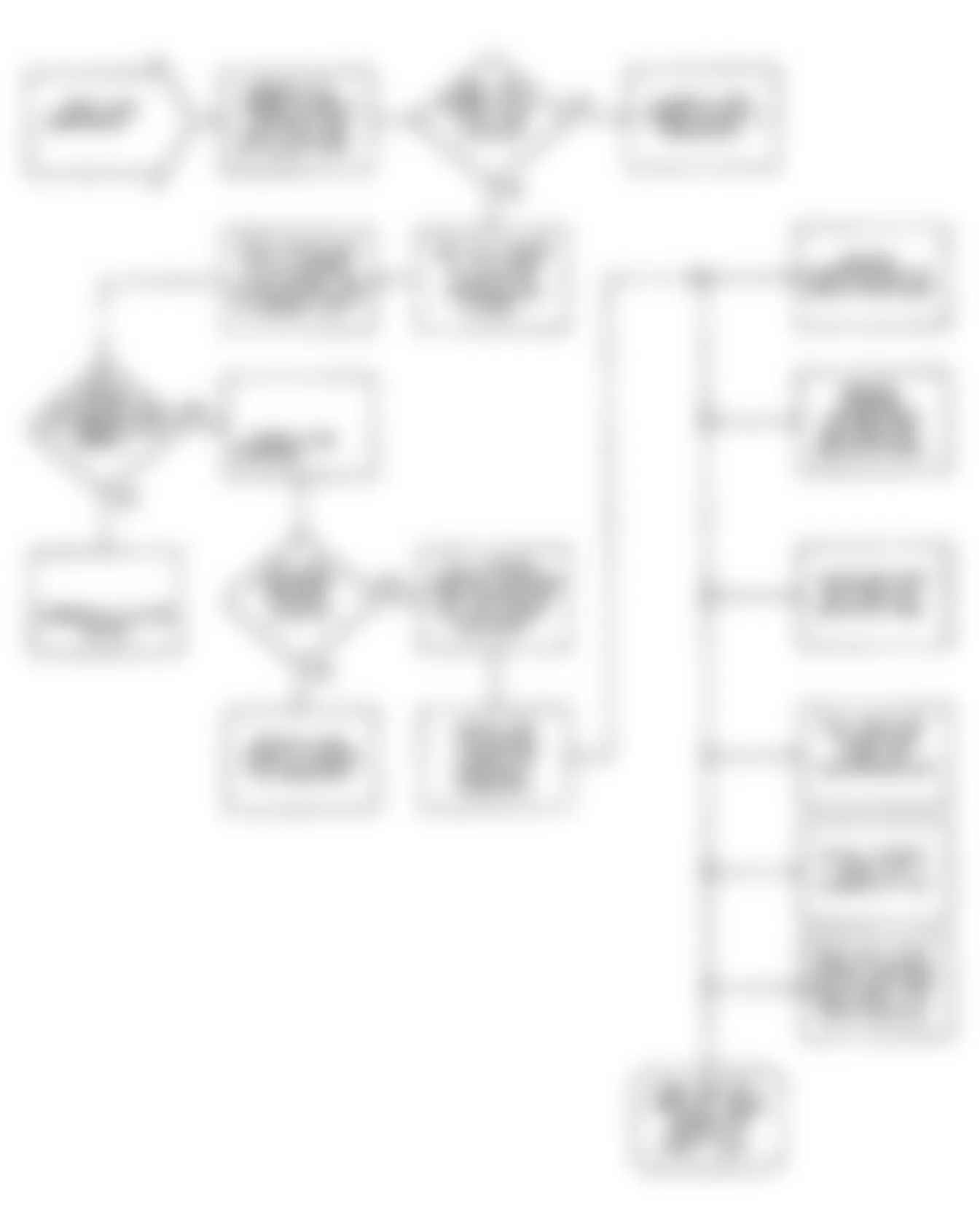
Jeep Wrangler S 1990 - SELF-DIAGNOSTIC SYSTEM
Jeep Wrangler S 1990 BODY CODE EXPLANATION
Model Body Code Wrangler YJ
Jeep Wrangler S 1990 - "HARD FAILURES"
Hard failures cause "malfunction" light to illuminate and remain on until the malfunction is repaired. If light comes on and remains on (light may flash) during vehicle operation, cause of malfunction must be determined using diagnostic (code) charts. If a sensor fails, control unit will use a substitute value in its calculations to continue engine operation. In this condition, vehicle is functional, but loss of good driveability will most likely be encountered.
Jeep Wrangler S 1990 - "INTERMITTENT FAILURES"
Intermittent failures may cause "malfunction" light to flicker or illuminate and go out after the intermittent fault goes away. The corresponding trouble code, however, will be retained in control unit memory. If related fault does not reoccur within a certain time frame, related trouble code will be erased from control unit memory. Intermittent failures may be caused by sensor, connector or wiring related problems. See INTERMITTENTS in TESTS W/O CODES article.

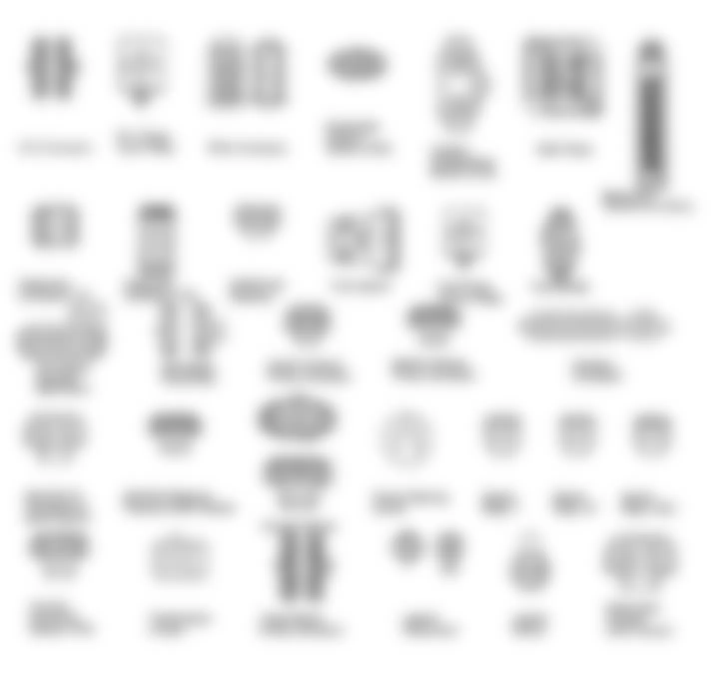
Fig. 1: Jeep Wrangler S 1990 - Component Locations - ECU Connector Terminal Identification
Jeep Wrangler S 1990 - PRELIMINARY CHECKS
Most driveability problems in the engine control system result from faulty wiring or leaking hose connections. To avoid unnecessary component testing, a visual check should be performed before beginning trouble shooting procedures to help spot these common faults.
Jeep Wrangler S 1990 - ECU CHECKOUT PROCEDURE
- If during testing the Electronic Control Unit (ECU) is found to be faulty, perform the following steps to ensure control unit is faulty. Most components are incorrectly diagnosed due to faulty electrical connectors or a poor mechanical connection between component and vehicle.
- Sometimes simply disconnecting and reconnecting an electrical component will provide a good electrical connection. Before replacing a control unit, check all components in the suspected circuit. If other components are okay, carefully disconnect control unit from vehicle harness.
- Inspect control unit harness connector and control unit contact pins for corrosion. Clean harness connector and control unit contact pins with contact cleaner. Inspect control unit harness connector for bent pins, missing pins and broken wires. Repair or replace as necessary.
- Connect control unit harness connector to control unit and retest system with DRB-II and adapter. If vehicle does not pass test and fails with the same message, replace control unit.
Jeep Wrangler S 1990 - DRB-II JEEP PROBLEMS
The most common problem is a blank screen. If after connecting DRB-II to vehicle, screen is blank, check the following:
- Ensure all connections are proper and fit correctly.
- Ensure wires in cables are not broken or shorted.
- Ensure diagnostic connector has power available to adaptor.
- Ensure cartridge is firmly installed in DRB-II.
If a defective DRB-II is encountered, generally the screen should not be blank when everything is connected the first time. Trying DRB-II with adaptor on another Jeep vehicle may help to isolate a faulty component.
Jeep Wrangler S 1990 - DIAGNOSIS WITH DRB-II & JEEP ADAPTER JEEP DRB-II ADAPTER
To properly interface with Jeep vehicles, an adapter must be attached to the DRB-II. The adapter is required as diagnostics on Jeep products are performed Off-Board. The adapter converts signals into a form the DRB-II can utilize in performing tests. Itself a powerful computer, the adapter MUST be used with the DRB-II when diagnosing Jeep vehicles.
The ECU has been programmed to monitor several different circuits of the engine control system. If a problem is sensed with a monitored circuit, a fault code is stored in the ECU.
The setting of a specific fault code is the result of a particular system failure, NOT the reason for that failure, such as failure of a specific component. The existence of a particular code denotes the probable area of the malfunction, not necessarily the failed component itself.
With DRB-II connected to Jeep adapter and Jeep adapter connected to both vehicle diagnostic connectors, all character positions will illuminate and copyright information will appear on screen. The DRB-II will offer 3 menus: VEHICLES TESTED, HOW TO USE and SELECT VEHICLE.
Jeep Wrangler S 1990 - VEHICLES TESTED
To enter VEHICLES TESTED, press "1" key or ENTER key when VEHICLES TESTED appears on DRB-II display. DRB-II will show vehicles supported with cartridge used. This screen will display for 5 seconds and return to DRB-II menu. To return to DRB-II menu sooner, press ATM key.
Jeep Wrangler S 1990 - HOW TO USE
To enter HOW TO USE menu option, press "2" key or press downward facing arrow button to display HOW TO USE option. Press ENTER key. DRB-II will display instructions for use of DRB-II with cartridge being used.
Jeep Wrangler S 1990 - SELECT VEHICLE
- The SELECT VEHICLE option provides a means which the user may enter information about vehicle being tested. Usually this option will have more than one display screen. Use ENTER key to enter vehicle information. If an option is not available for vehicle being tested, DRB-II will not display that option.
- When all information about the vehicle is entered, DRB-II will display a summary of information technician entered as a confirming menu. DRB-II will show an additional option marked CONFIRM. If information is correct, press CONFIRM. DRB-II will display MAIN MENU.
Jeep Wrangler S 1990 - MAIN MENU
The MAIN MENU will present all diagnostic functions available for vehicle selected. Functions are SYSTEM TESTS, STATE DISPLAYS and ADJUSTMENTS.
Jeep Wrangler S 1990 - DIAGNOSIS & SYSTEM TESTING
- This is an interactive functional test of a particular system. During testing, DRB-II will provide instructions to technician. After task is performed, press ENTER key. A fault will be generated since the technician has performed a requested action and tester had not seen any indication from the diagnostic pins.
- Some tests such as engine coolant temperature sensor require longer periods before the circuit is automatically faulted (depending on ambient temperature).
- If a correct operating condition is not seen within a preprogrammed amount of time, the DRB-II keyboard is locked out. If there is a circuit problem, the test must time-out (the ENTER key cannot be used to force an error condition).
- After performing a SYSTEM TEST, if the DRB-II was unable to detect a fault with the system, the DRB-II will display VEHICLE PASSES ELECTRICAL TEST.
- One of the following alpha characters may appear as a prefix to a fault code. The character displayed can be used as an indication of where in the engine test sequence the fault was detected. Alpha prefixes are displayed only during a SYSTEM TEST.
- "A" (First Key Off) Ignition switch in the OFF position.
- "B" (Key On Before Fuel Pump Drops Out) Ignition switch in the ON position. Fuel Pump Drops Out refers to fuel pump relay being activated by the ECU and fuel pump being activated. If the ECU does not detect a crank signal within a few seconds after ignition is turned on, the ECU will automatically open ground circuit to fuel pump relay. This will disable the fuel pump.
- "C" (Key On After Fuel Pump Drops Out) Ignition switch is in the ON position after fuel pump relay has timed out (fuel pump off).
- "D" (First Crank) The engine is cranking but not running.
- "E" (First Engine Start) Engine idling.
- "F" (Second Key Off Before Fuel Pump Drops Out) Ignition switch is in the OFF position for the second time before fuel pump relay has timed out.
- "G" (Second Key Off After Fuel Pump Drops Out) Ignition switch is in the OFF position for the second time before fuel pump relay has timed out.
- "G" (Second Key On) No text.
- "I" (Second Engine Start) No text.
- "J" (Last Key Off) No text.
- "X" (ECU Defined Faults) Faults detected by ECU on-board diagnostics.
Jeep Wrangler S 1990 - STATE DISPLAYS
- This display enables technician to view conditions at the signal level. The 2 types of signals used are analog and digital. Analog signals are monitored at pins corresponding to vehicle harness splices (e.g. fuel pump relay). Digital signals correspond to data transmitted by the system controllers. Both signals are displayed in common units (e.g. temperature), this information is not relative to diagnostic intent.
- Use up and down arrow keys on DRB-II to scroll through displays available. When STATE DISPLAY is selected, a menu showing systems for which state displays are supported is displayed. If ENGINE state display is selected, technician has the option to view either static state displays or MAX/CURRENT/MIN value display.
- The STATIC display shows conditions as they exist at the time the user is viewing the display. The MIN/CURRENT/MAX display shows a history of conditions for specific sensor. When this option is selected, maximum, current (static) and minimum value can be displayed for a specific sensor. To reset sensors to a zero value, simply press the ENTER key. This display may be used to isolate intermittent faults.
- The following ENGINE state displays are available on the DRB-II.
- Vehicle Program and Calibration Code Program numbers indicate the ECU is programmed for a specific engine. Calibration code applies to manual or automatic transmission.
- Battery Displays battery voltage.
- H2O Engine coolant temperature is displayed in degrees Fahrenheit and Celsius.
- Air Air temperature is displayed in degrees Fahrenheit and Celsius.
- TPS Throttle Position Sensor (TPS) is displayed as WIDE OPEN, CLOSED or PARTIAL and percentage of opening from closed throttle to Wide Open Throttle (WOT).
- A/C Status If any of the A/C signals are active, an abbreviated display showing A/C state will be displayed as select SELL, predict PRE, clutch CL and cut-out CO. If A/C signals are inactive, A/C OFF will be displayed.
- Relay Status Displays EGR solenoid, B+ latch relay and fuel pump control relay as on "+" or off "0". When EGR solenoid is off, vacuum is present. When EGR solenoid is on, vacuum is absent.
- Barometric Pressure Reading Barometric pressure value can be used to test MAP sensor. A good MAP sensor will read within .60 in. Hg of current barometric pressure at sea level. Subtract .1 in. Hg for every 100 feet above sea level. Current barometric pressure may be obtained from your local weather bureau.
- RPM Engine speed is displayed.
- Exhaust Oxygen Sensor Displays voltage from O2 sensor and whether fuel system is RICH or LEAN. Displays if system is in DECEL condition or in OPEN LOOP.
- Pulse Width Displays the amount of time in milliseconds that the fuel injector is open.
- Knock Displays knock sensor noise volume in units from 0-255. If display is more than 250, this will generally indicate a short circuit. Normal readings of a functional knock sensor will be more than 5. A short to ground, open circuit or a non-functioning knock sensor will generally not cause a value above 5 to be displayed.
- ALFACL The closed loop pulse width correction factor is displayed in units from 0-255. ALFACL represents the correction used to calculate injector pulse width in response to oxygen sensor input. If oxygen sensor reads rich, ALFACL will decrease. If oxygen sensor reads lean, ALFACL will increase.
- CTAVE This is average closed throttle value displayed as a percentage of full scale. The closed throttle switch provides a signal to the ECU to indicate closed throttle status.
- KAM Keep Alive Memory (KAM) faults are displayed for the O2 sensor, MAP sensor, TPS, air temperature sensor and coolant temperature sensor. Next to sensor display, a pair of numbers is displayed. Each number reflects a period since the ECU has detected a fault. The first number corresponds to a sensed "low" condition failure and the second number corresponds to a sensed "high" condition failure. When ECU detects a "low" or "high" condition failure, then number "15" will be stored for the respective sensor. If the engine is started and closed loop is attempted and fault is no longer present, the counter will be decreased by one. If the fault is still present, counter will remain at 15. Values of "0" (zero) are an indication that a "low" or "high" fault condition does not exist for the sensor displayed. Values less than 15 and greater than zero are an indication that the ECU has detected a fault at some time, but fault is not present during the current start cycle (possible intermittent).
- Warranty A 6-digit code for warranty reporting.
- The Min/Current/Max display allows technician to observe operation of 6 different sensor values. Information is displayed as a 3 digit number. The first value displayed is the minimum reading, second number displayed is current reading and third value displayed is the maximum reading. The sensors that are monitored are: MAP sensor, O2 sensor, Throttle Position Sensor (TPS), Coolant Temperature Sensor (CTS), Manifold Air Temperature (MAT) sensor and CTAVG (average learned closed throttle value).
- Typically sensors range between 2-252. Values less than 2 or greater than 252 will usually indicate that a sensor is shorted or disconnected. Watch minimum and maximum values to help diagnose intermittent problems.
Jeep Wrangler S 1990 - CLEARING CODES
The Adjustments option provides TPS adjustment or erasing stored information in system controller. Follow DRB-II instructions to accomplish desired task.
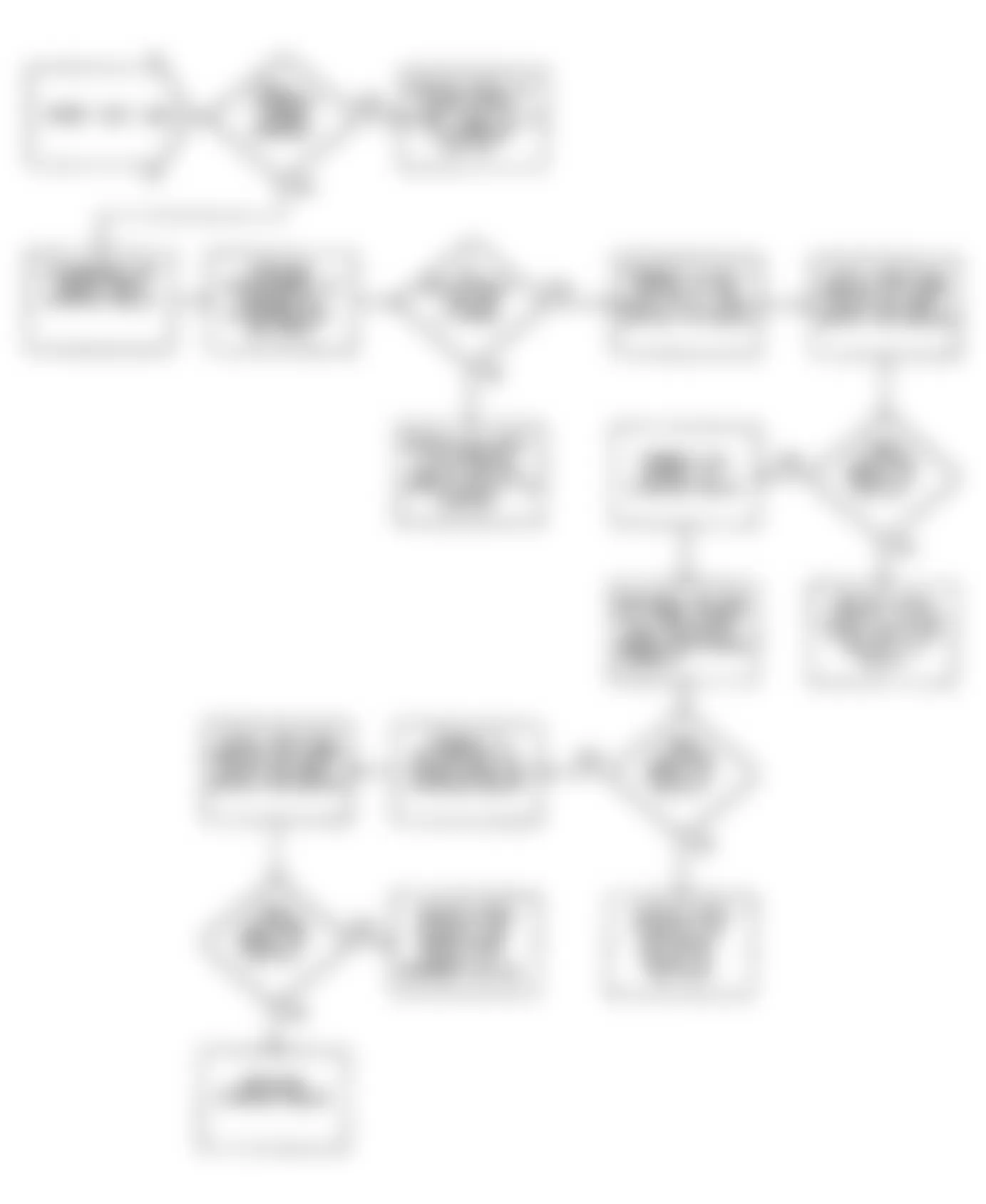
Jeep Wrangler S 1990 - DIAGNOSTIC TROUBLE CODE (DTC) IDENTIFICATION
Jeep Wrangler S 1990 DIAGNOSTIC TROUBLE CODE (DTC) IDENTIFICATION
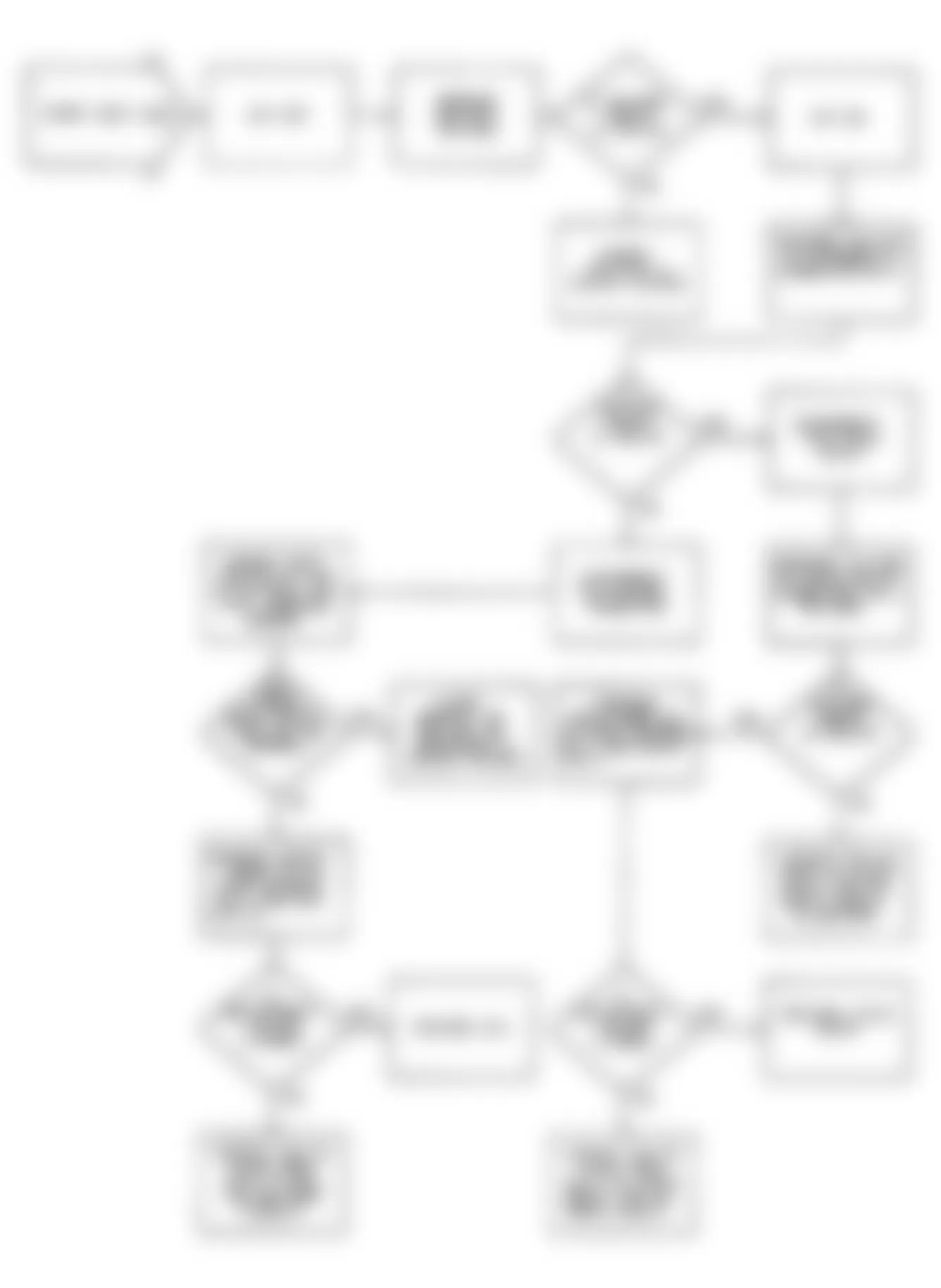
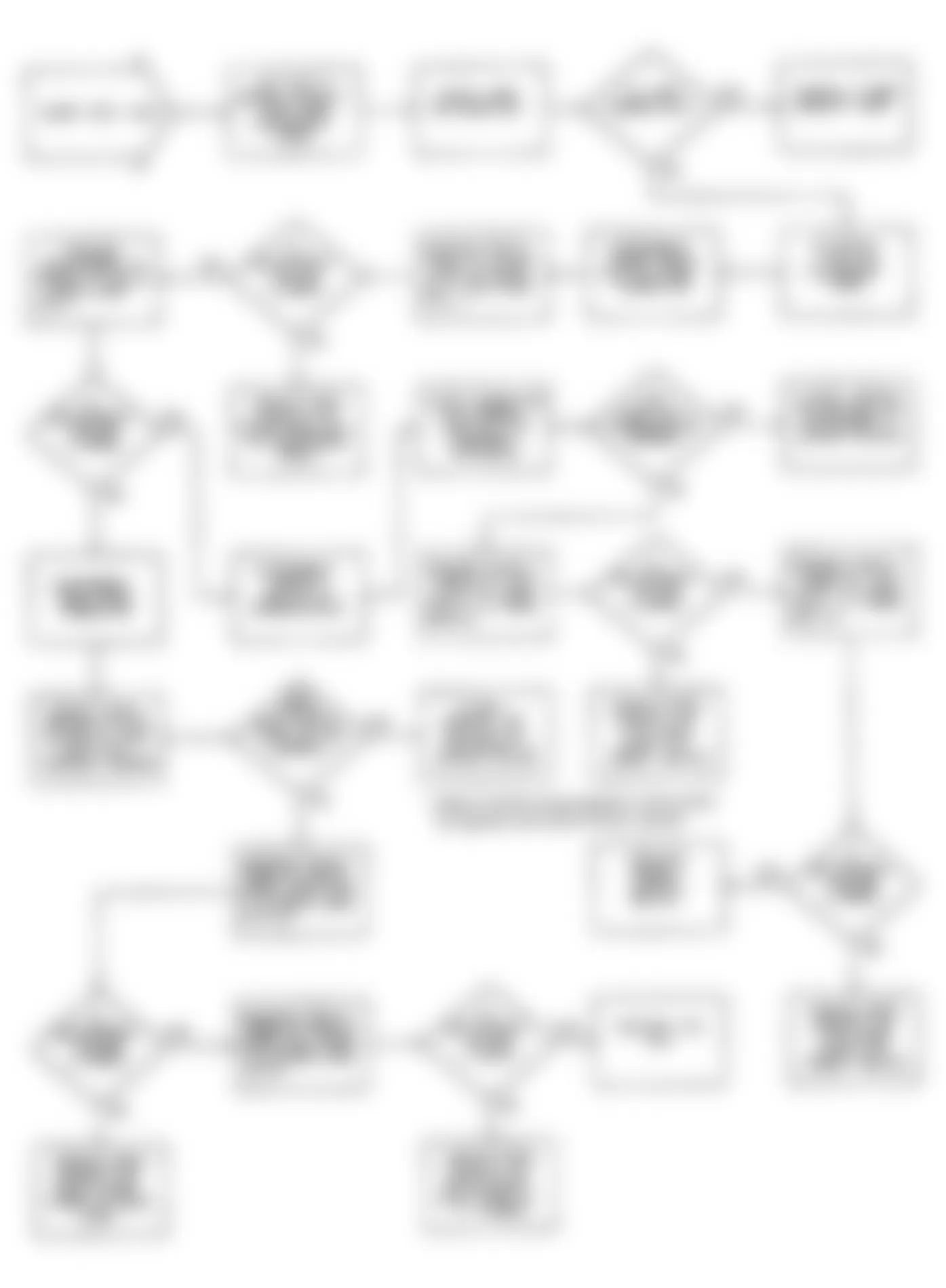
Fault Code Fault Condition 1000 Ignition circuit low. 1001 Ignition circuit high. 1004 ECU battery feed and power grounds. 1005 System ground circuit. 1006 EGR solenoid circuit low. 1007 EGR solenoid circuit high. 1008 Power steering circuit low. 1009 Power steering circuit high. 1012 Fuel injector circuits. 1013 Ignition module (MPA) circuit high. 1014 Fuel pump circuit low. 1015 Fuel pump circuit high. 1016 Manifold Air Temperature (MAT) circuit low. 1017 Manifold Air Temperature (MAT) circuit high. 1018 Serial data circuit. 1019 Power latch not set. 1021 Engine failed to start. 1022 Starter relay circuit low. 1024 No start signal at ECU. 1025 Wide Open Throttle (WOT) circuit low. 1027 Injector control circuit low. 1028 Wide Open Throttle (WOT) circuit low. 1029 Idle Speed Actuator (ISA) closed throttle circuit low. 1030 Idle Speed Actuator (ISA) closed throttle circuit high. 1031 ECU closed throttle circuit low. 1032 ECU closed throttle circuit high. 1033-36 Idle Speed Actuator (ISA) circuits. 1037 Throttle Position Sensor (TPS) circuit low. 1038 Serial data enable circuit high. 1039 Serial data enable circuit low. 1040 Power latch relay circuit low. 1041 Power latch relay circuit high. 1042 Charging and ECU circuits. 1043 Shift light circuit low. 1044 Shift light circuit high. 1048 Checking manual transmission vehicle for correct ECU. 1050 Idle RPM low. 1051 Idle RPM high. 1052 Manifold Absolute Pressure (MAP) sensor circuits. 1053 Manifold Absolute Pressure (MAP) sensor ground circuit. 1054 Coolant sensor and 5-volt supply to TPS/MAP circuit low. 1055 Coolant sensor circuit high. 1056 Inactive coolant temperature sensor. 1065 Lean O2 sensor input. 1066 Rich O2 sensor input. 1067 Latch relay circuit low. 1068 Latch relay circuit high. 1069 Speed sensor and ignition module (MPA) circuits.
NOTE: Compare fault code to appropriate diagnostic chart.
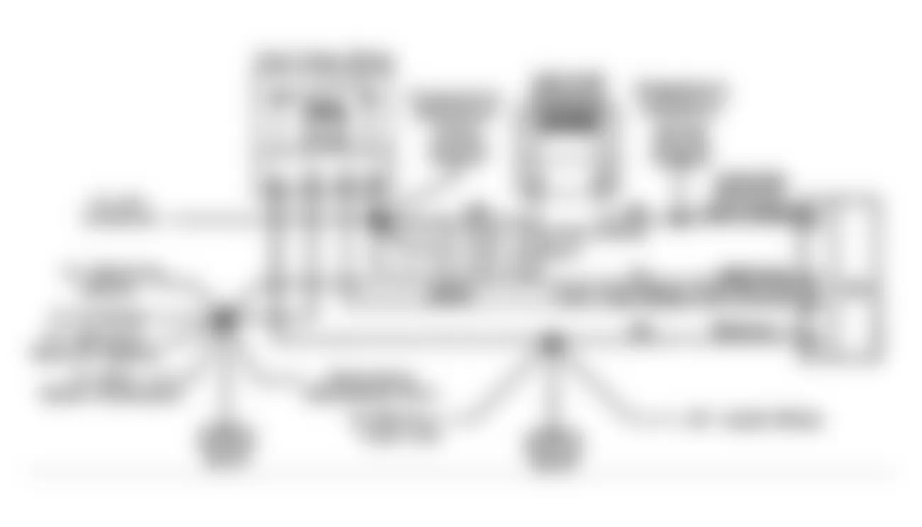
Jeep Wrangler S 1990 - ECU LOCATION
ECU is located under the instrument panel between the steering column and the A/C-heater housing. See Fig. 3 .
Fig. 3: Jeep Wrangler S 1990 - Component Locations - ECU Location

Jeep Wrangler S 1990 - SUMMARY
If no hard fault codes (or only pass codes) are present, driveability symptoms exist or intermittent codes exist, proceed to TESTS W/O CODES article for diagnosis by symptom (i.e. ROUGH IDLE, NO START, etc.), or intermittent diagnostic procedures.
Fig. 4: Jeep Wrangler S 1990 - Component Locations - Connector Identification
NOTE: The following schematics and charts are courtesy of Chrysler Motors.
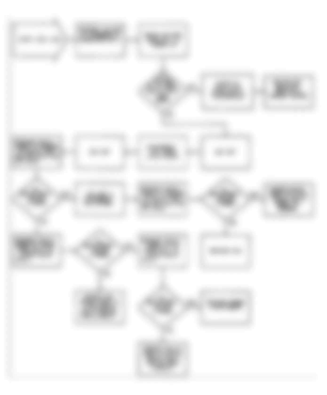
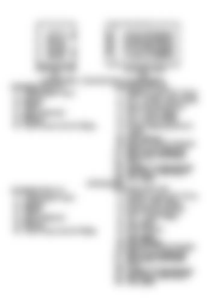
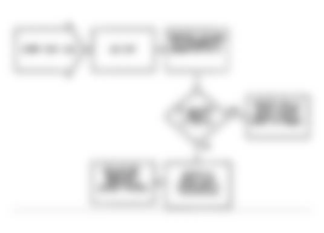
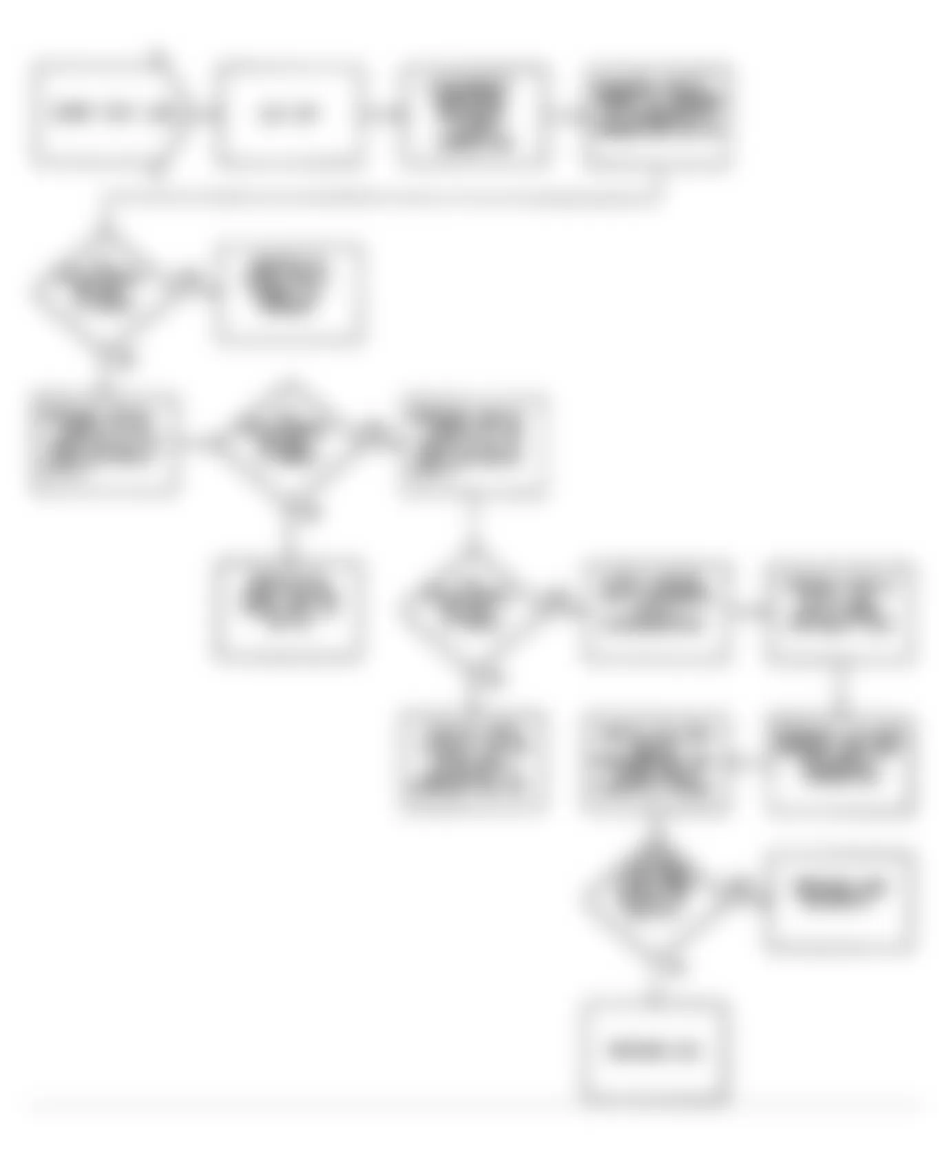
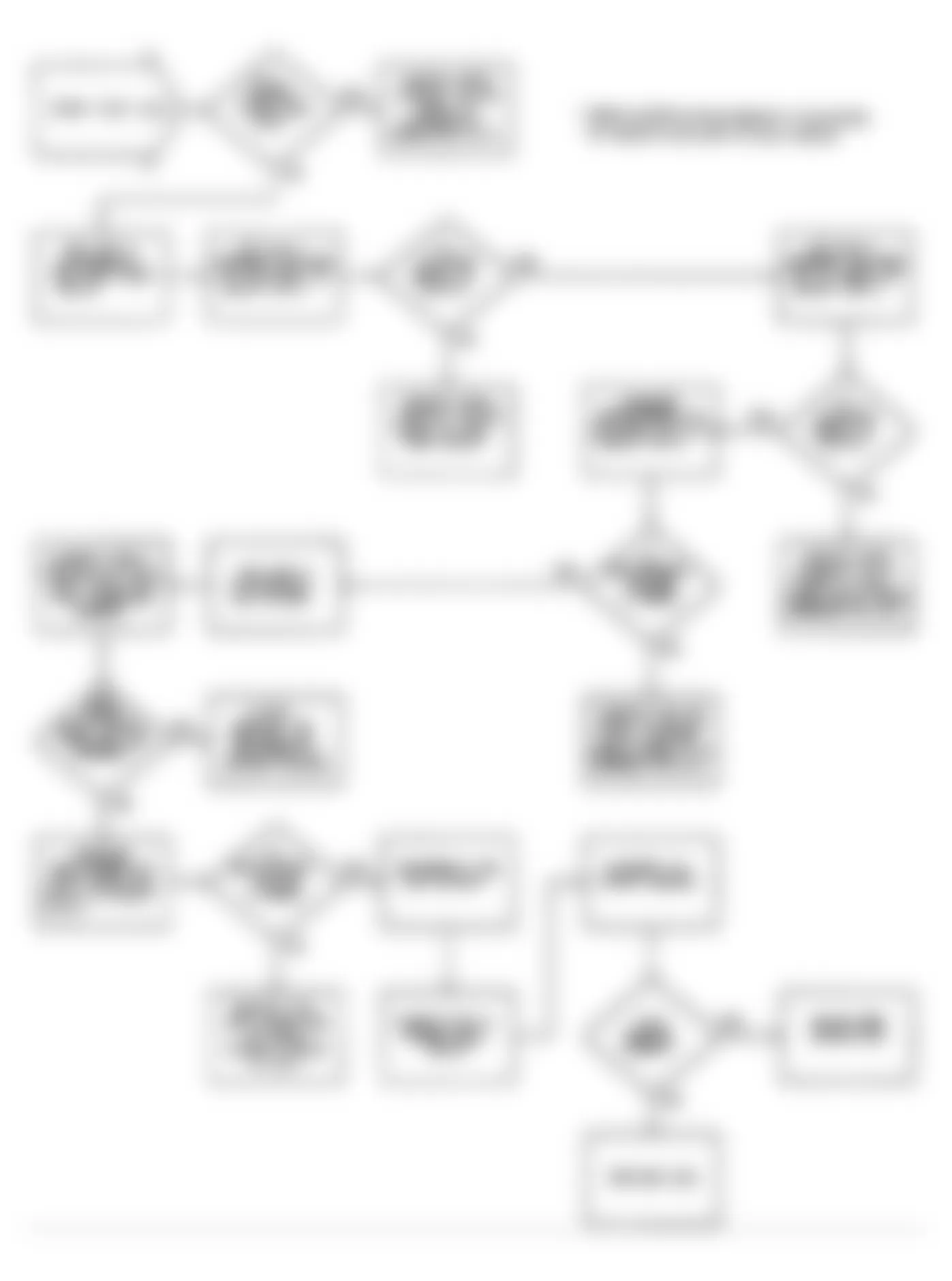
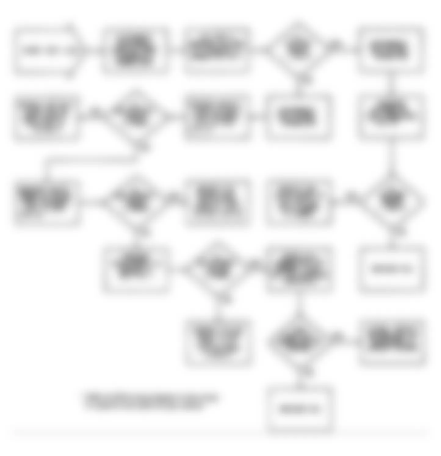
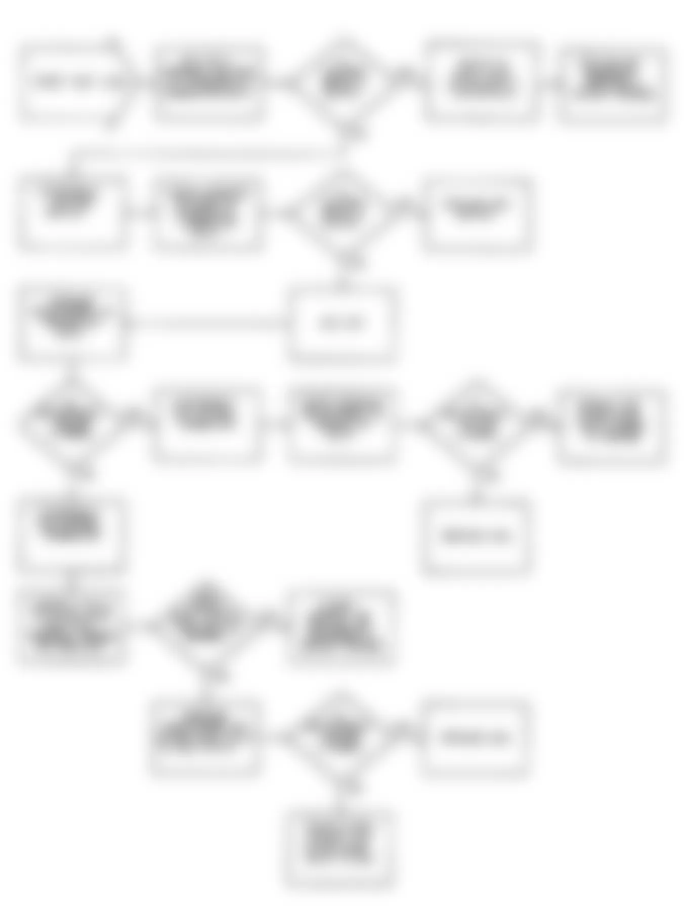
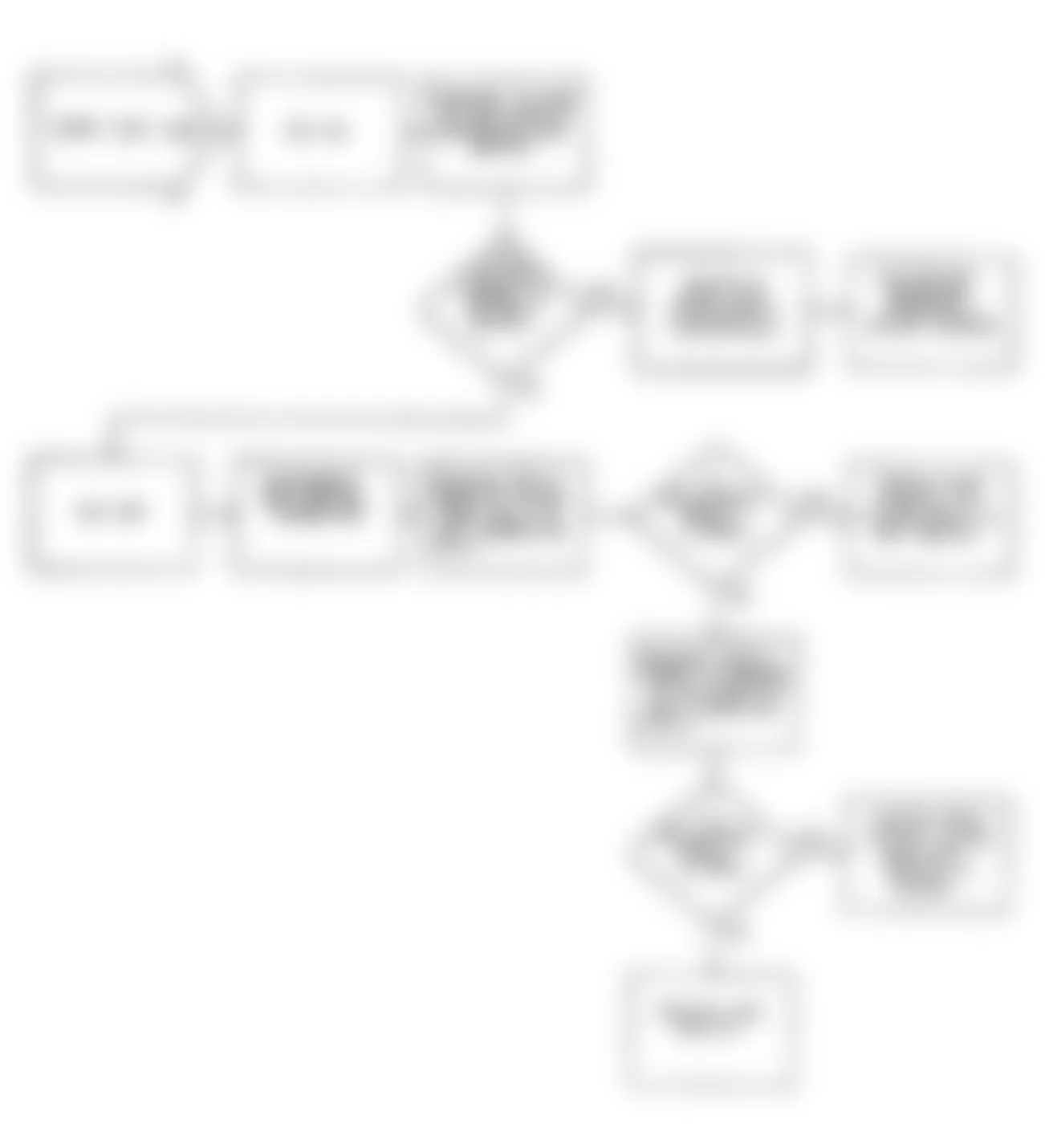
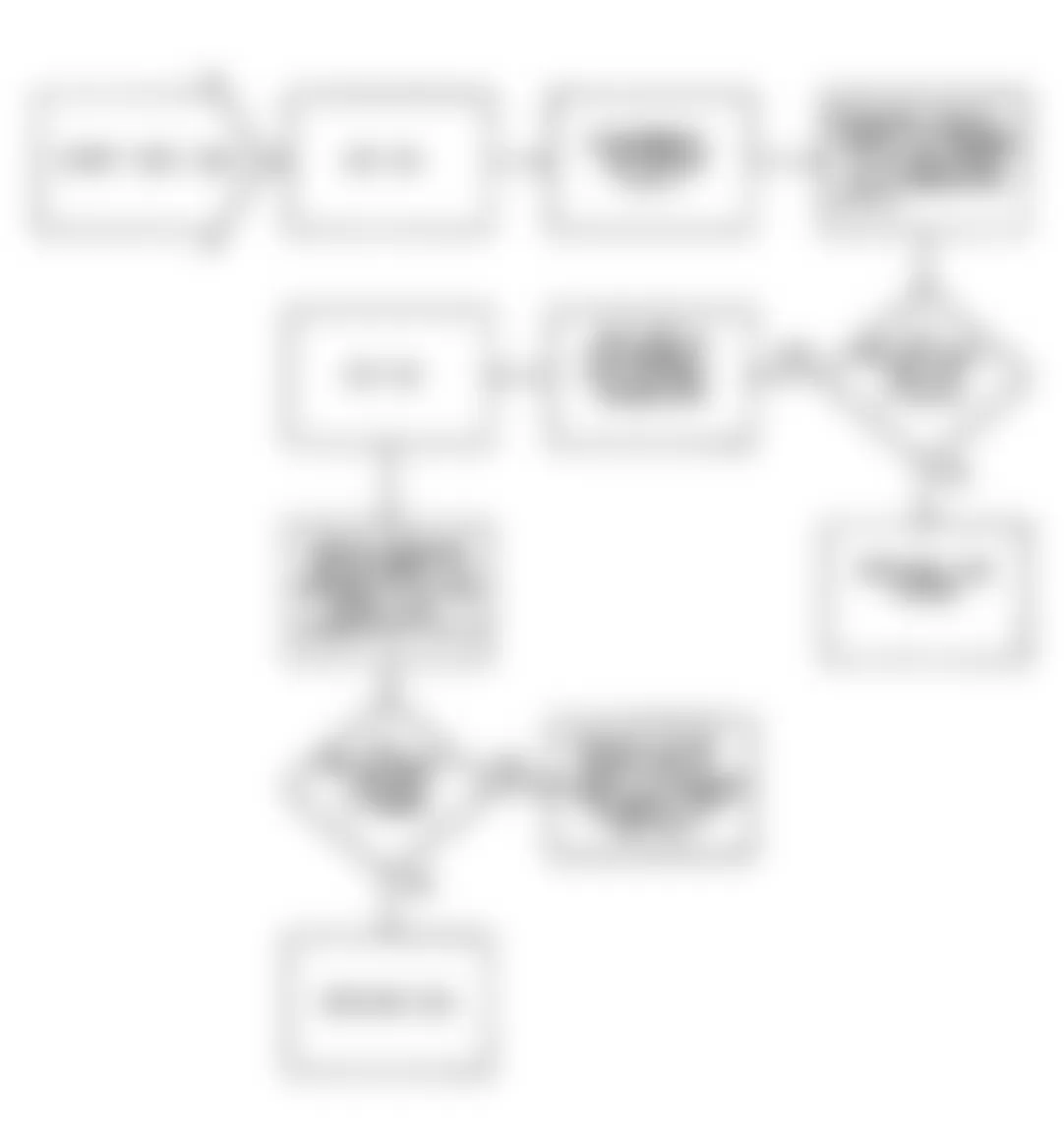
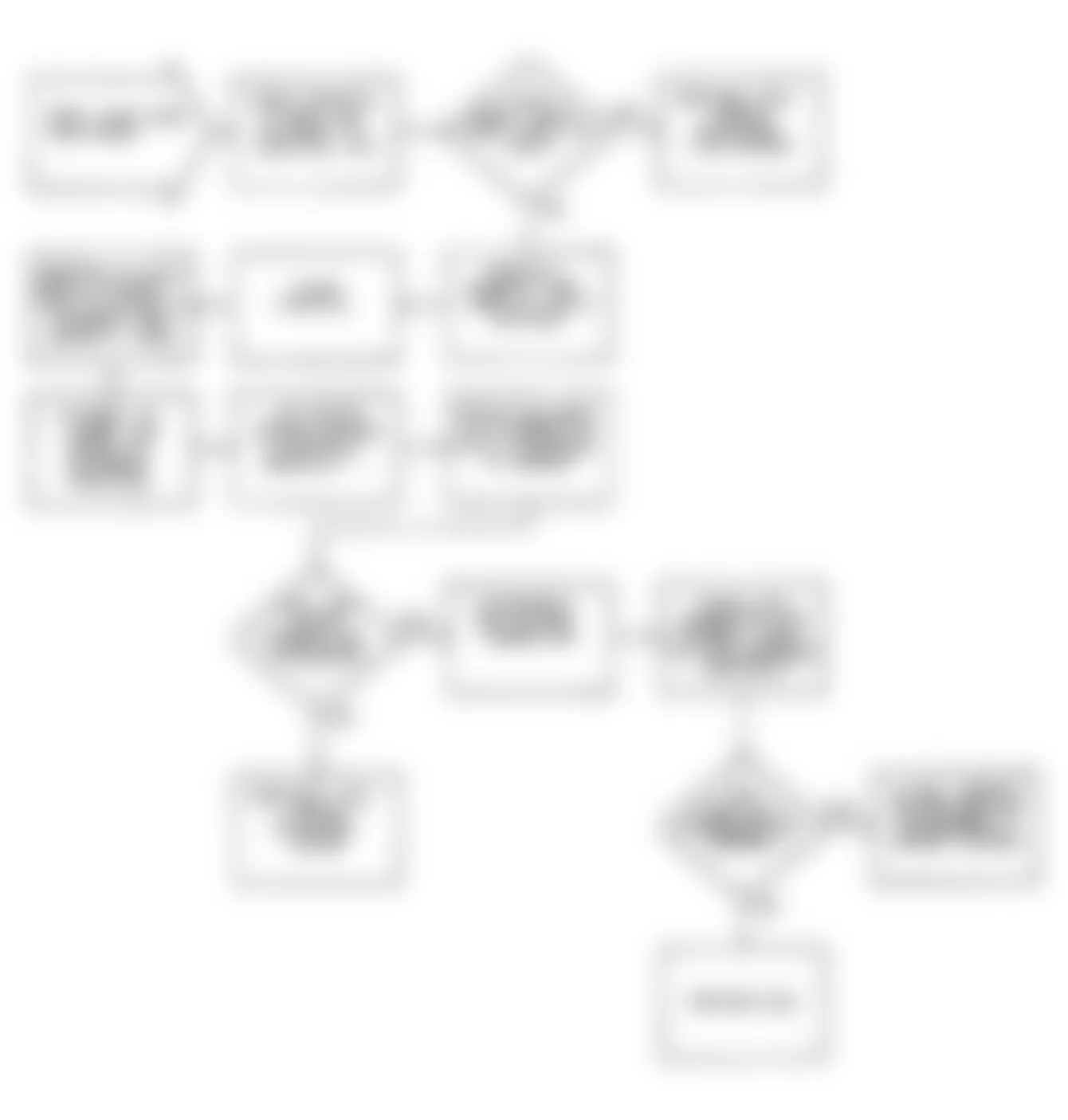
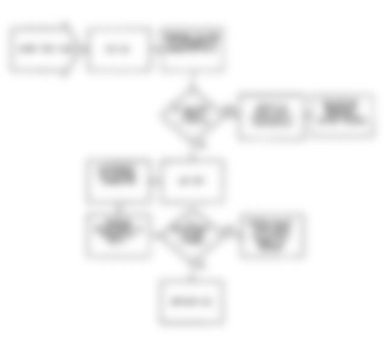
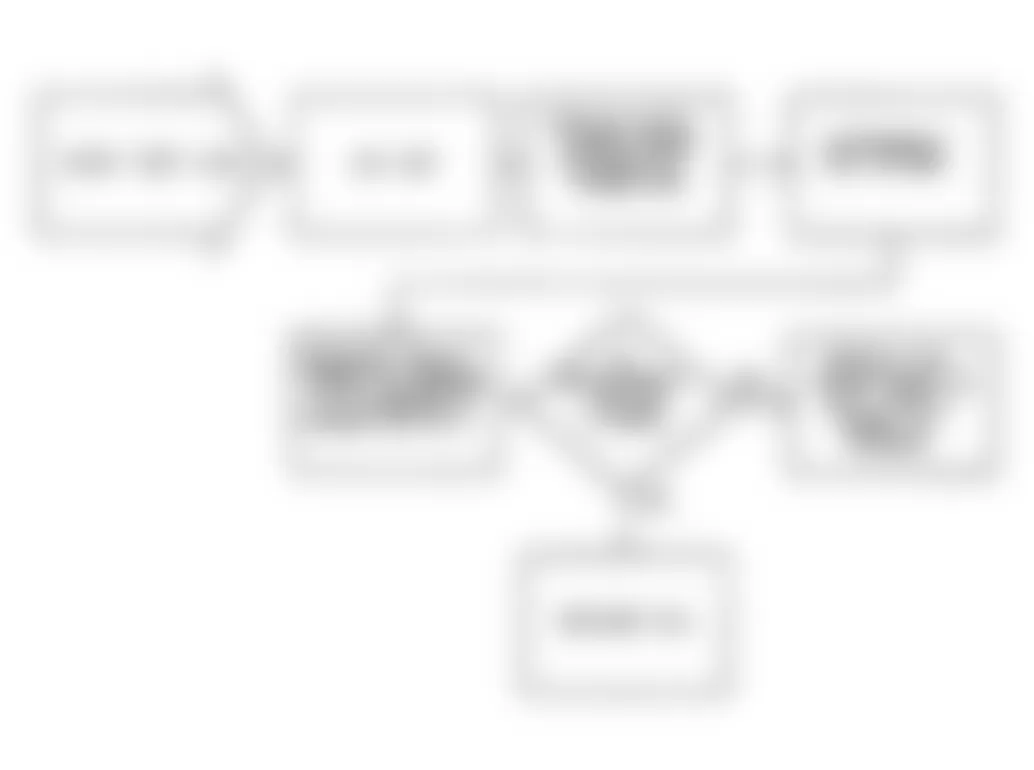
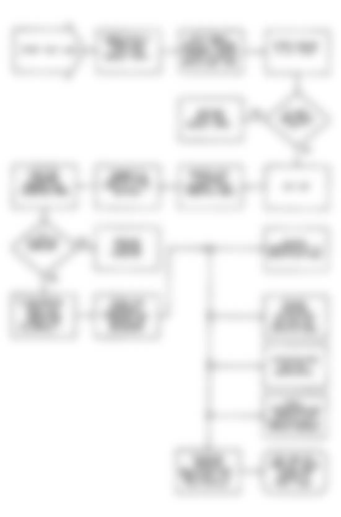
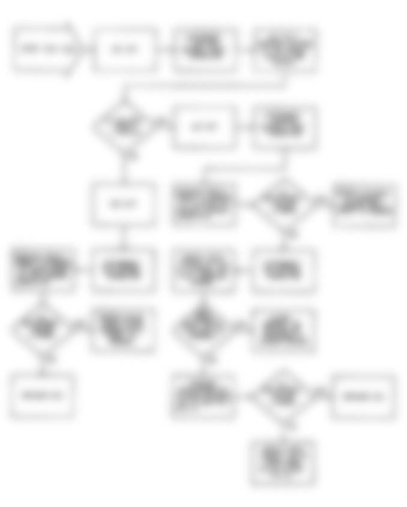
Jeep Wrangler S 1990 - DIAGNOSTIC TROUBLE CODE (DTC) CHARTS FAULT 1000: IGNITION CIRCUIT LOW

Fig. 6: Jeep Wrangler S 1990 - Component Locations - Fault 1000: Flow Chart Ignition Circuit Low
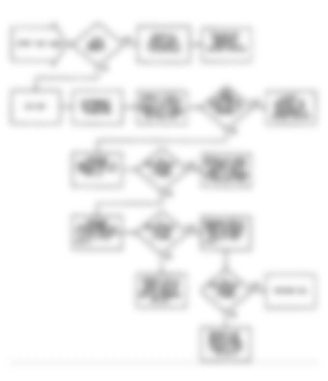
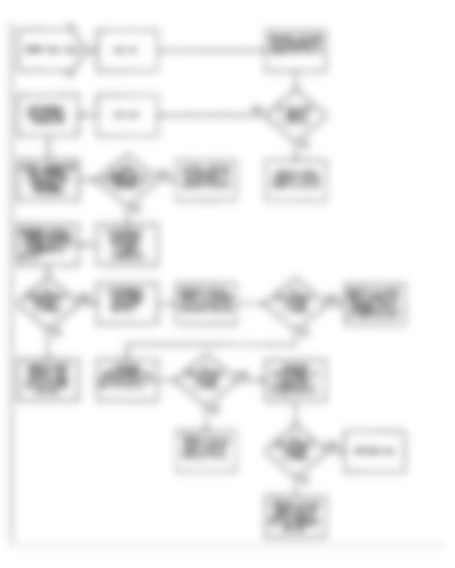
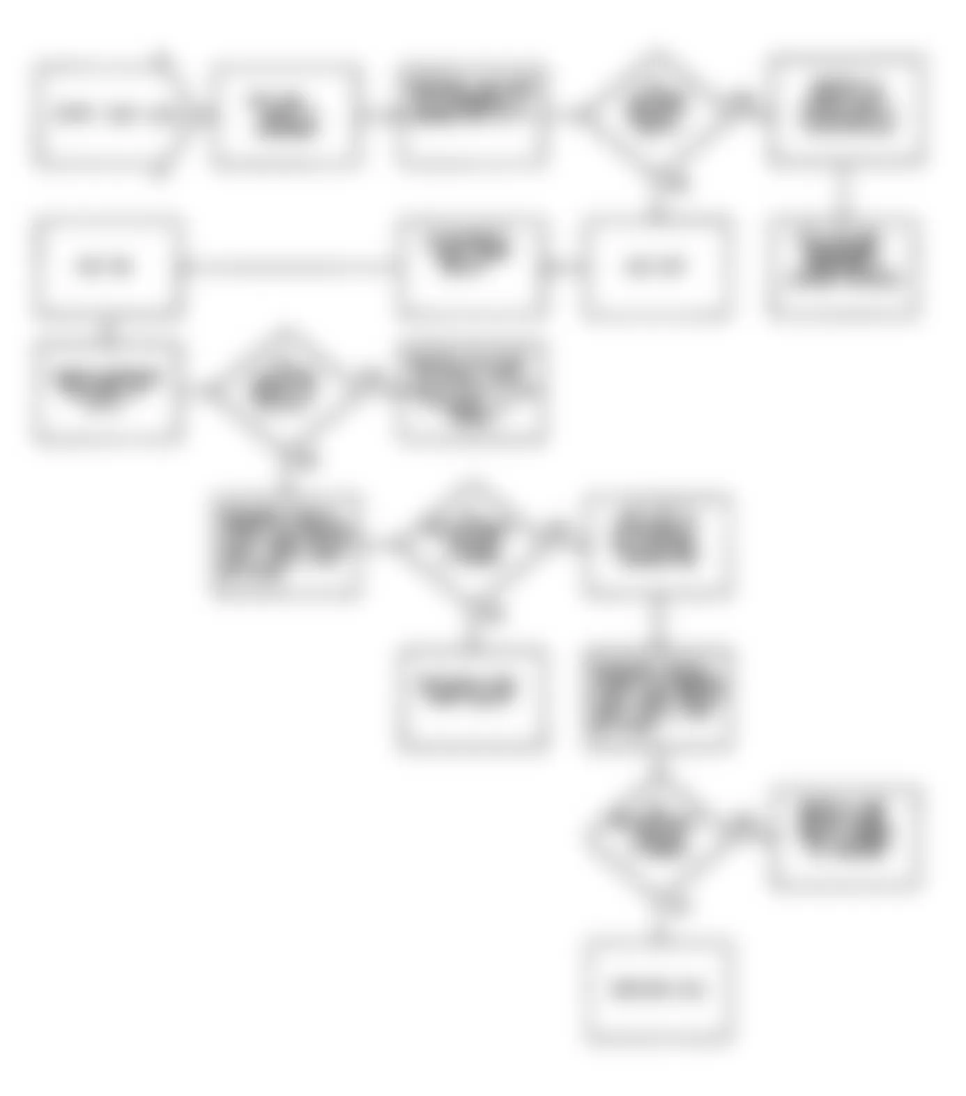
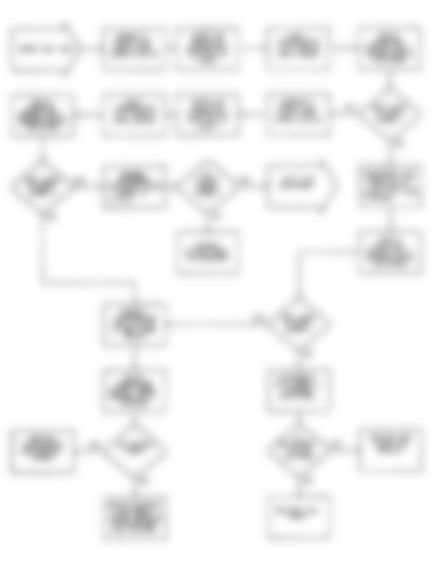
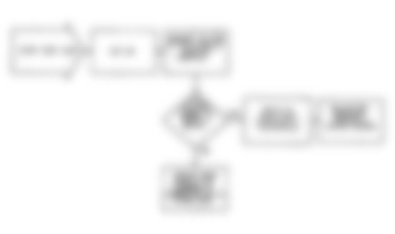
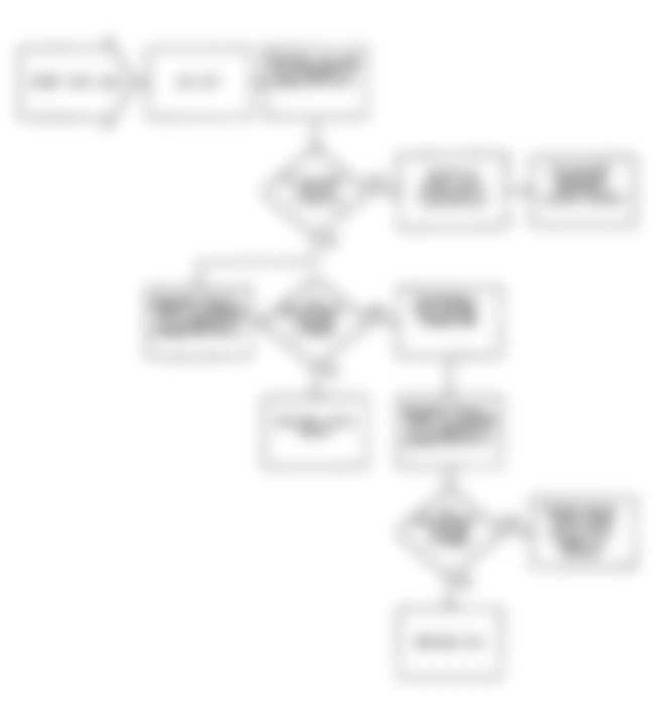
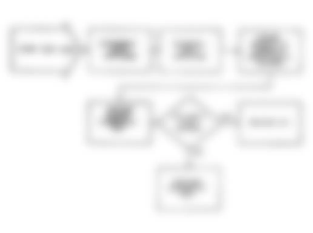
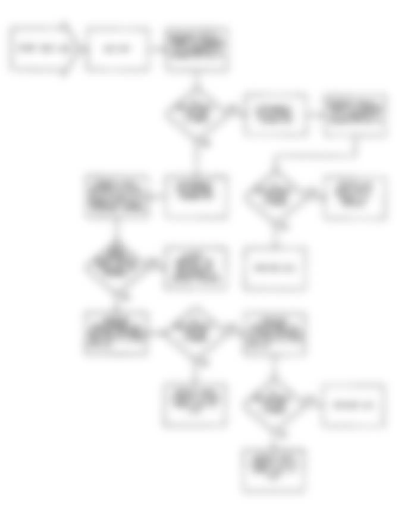
Jeep Wrangler S 1990 - FAULT 1001: IGNITION CIRCUIT HIGH
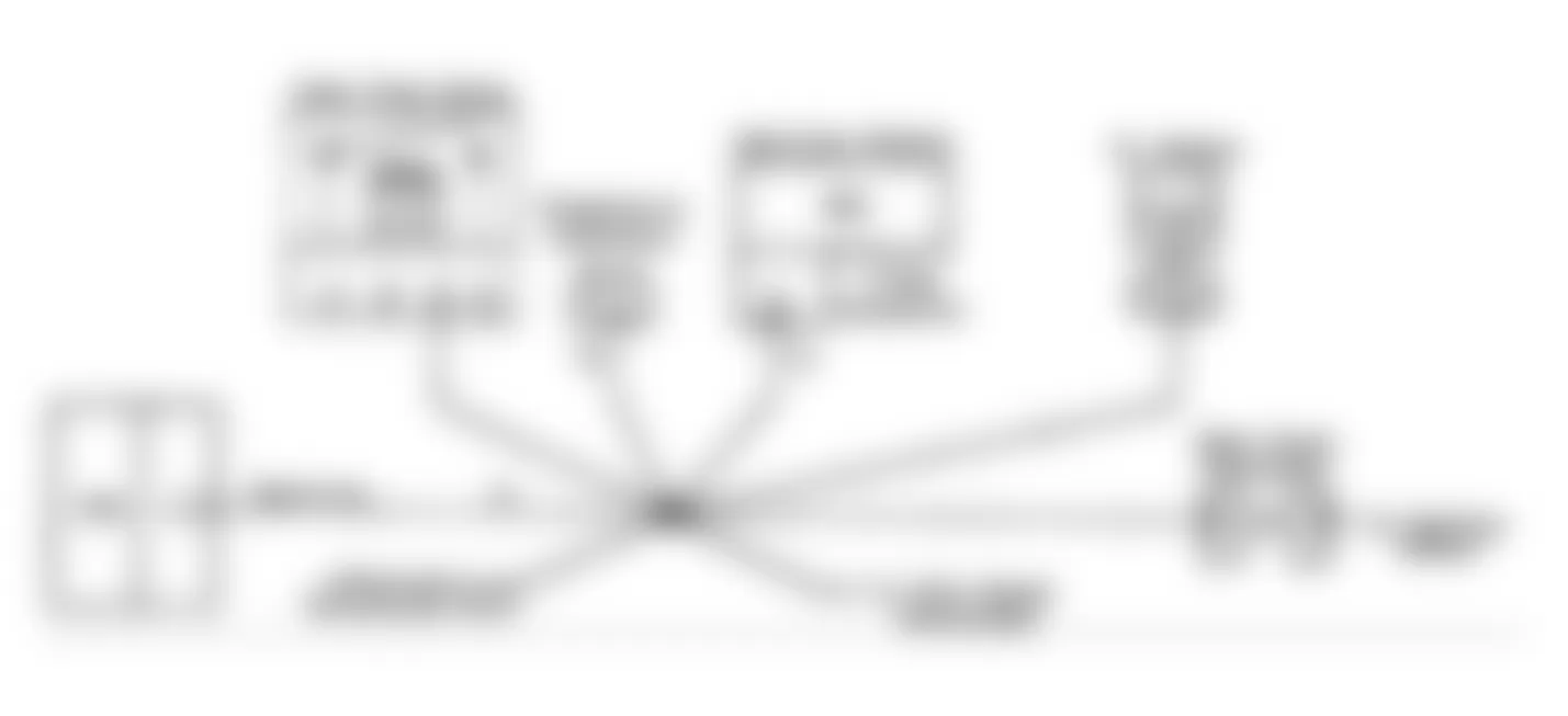
Fig. 8: Jeep Wrangler S 1990 - Component Locations - Fault 1001: Flow Chart Ignition Circuit High
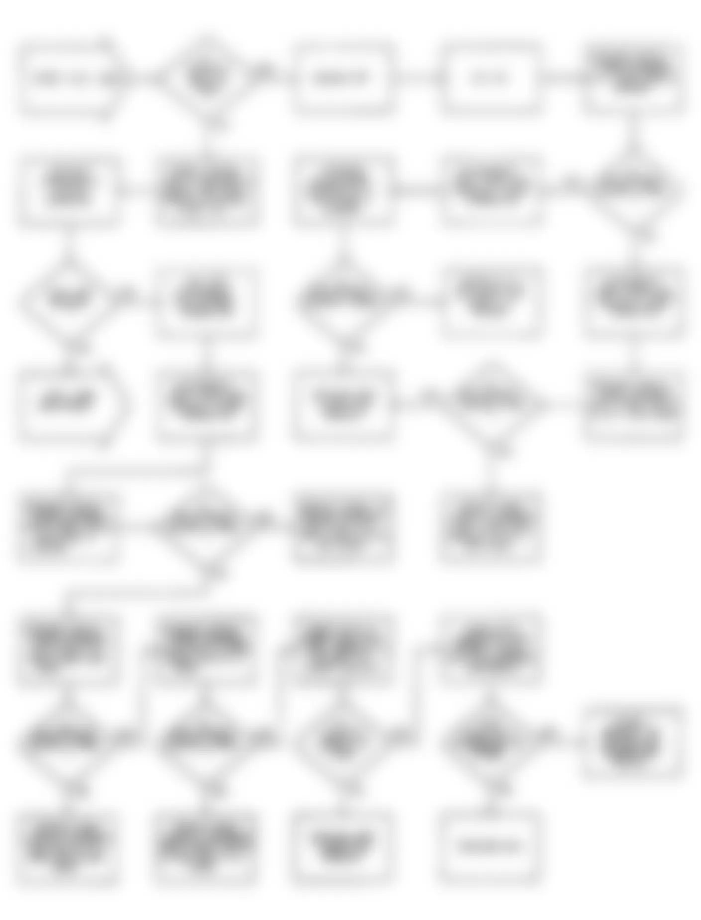
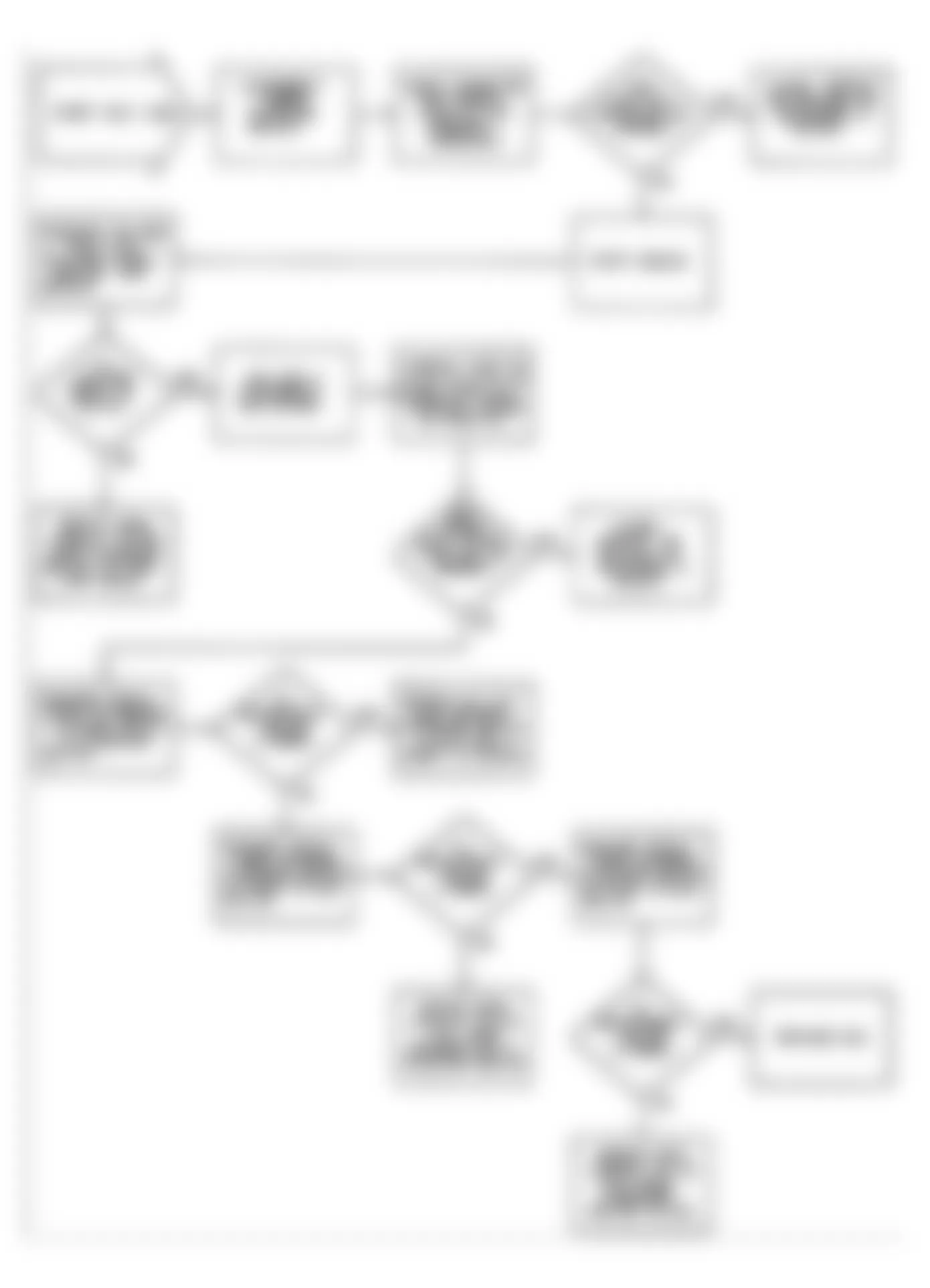
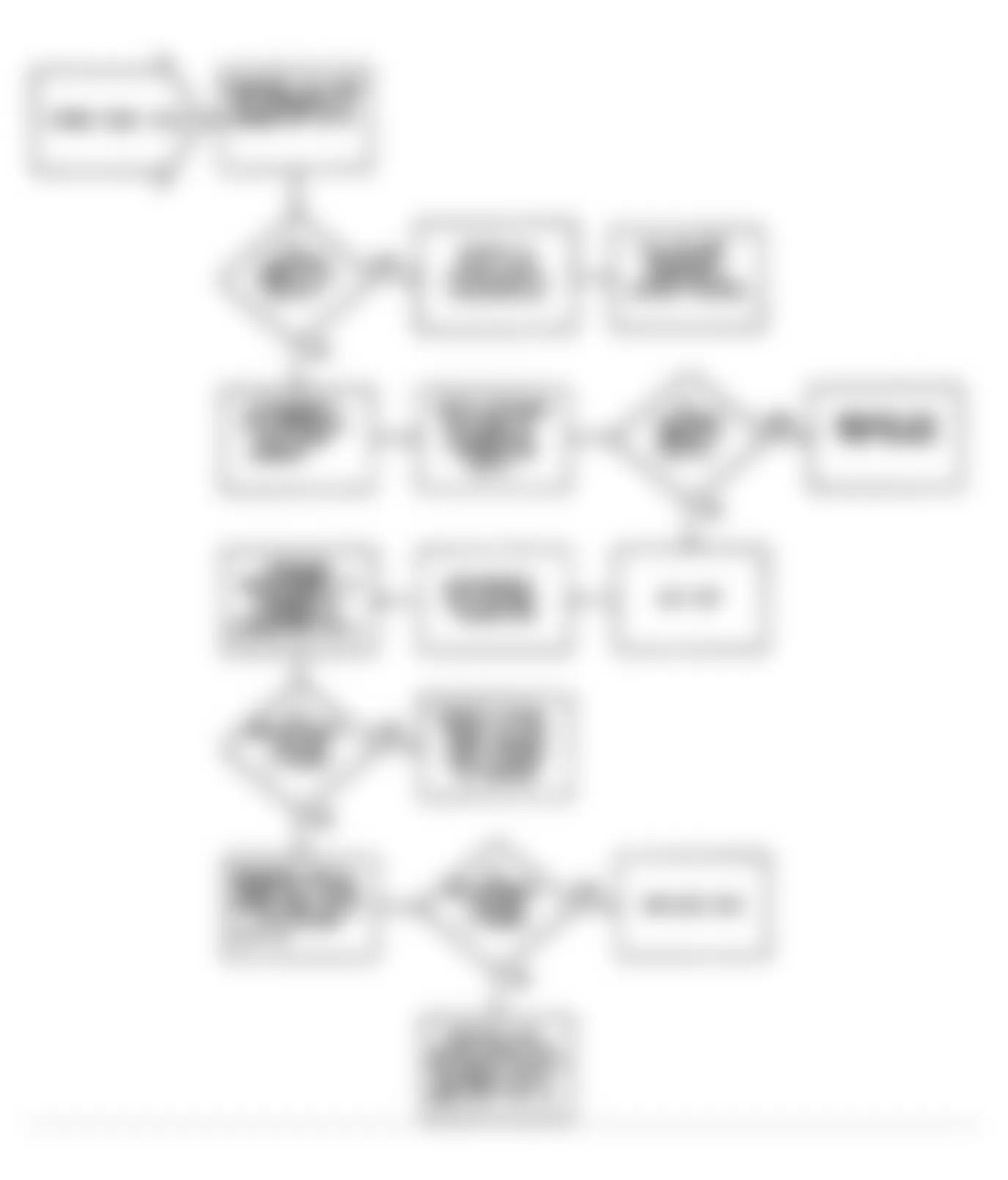
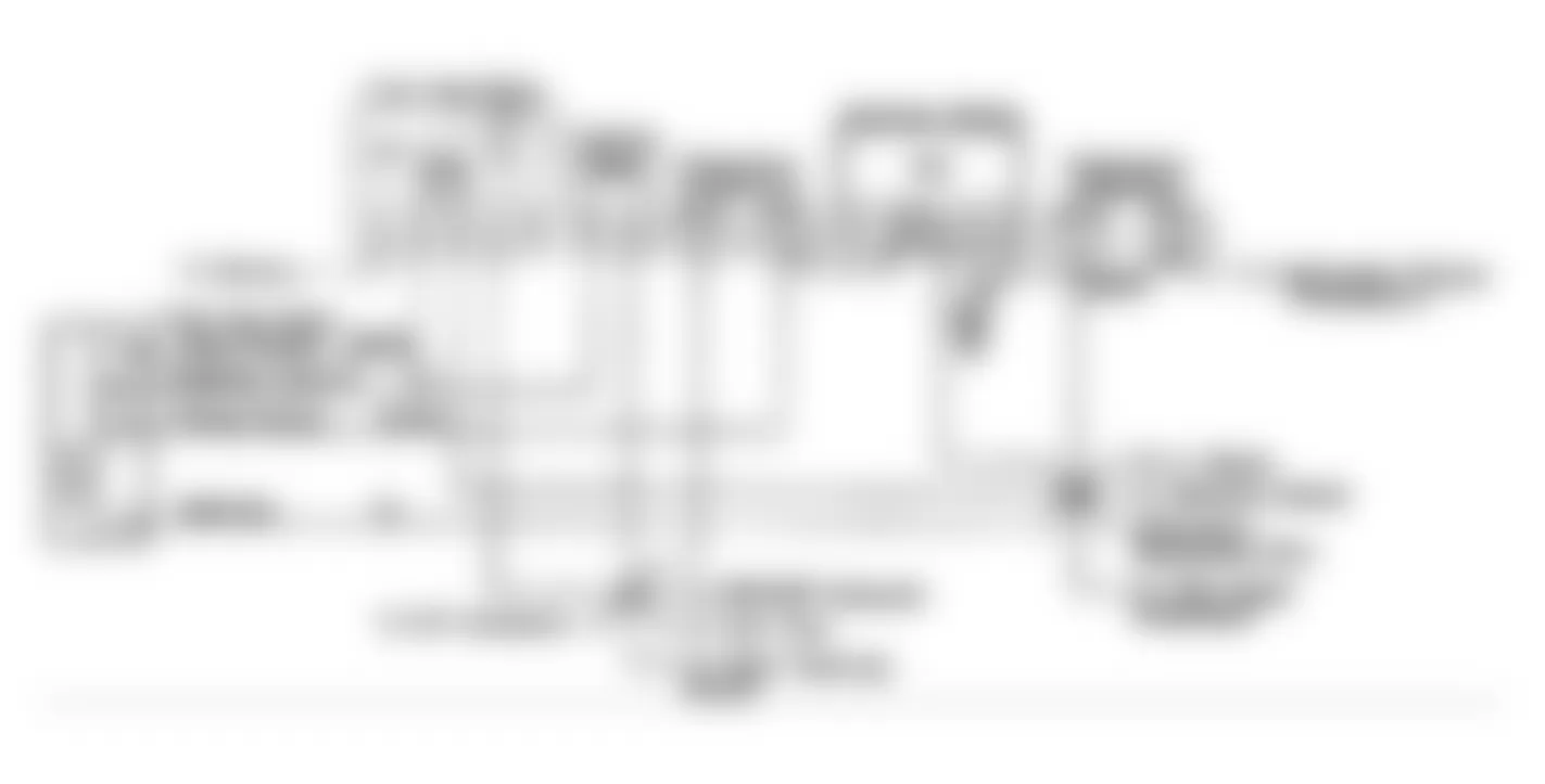
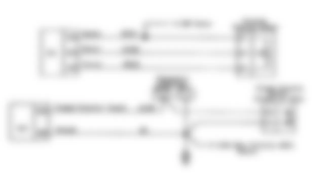
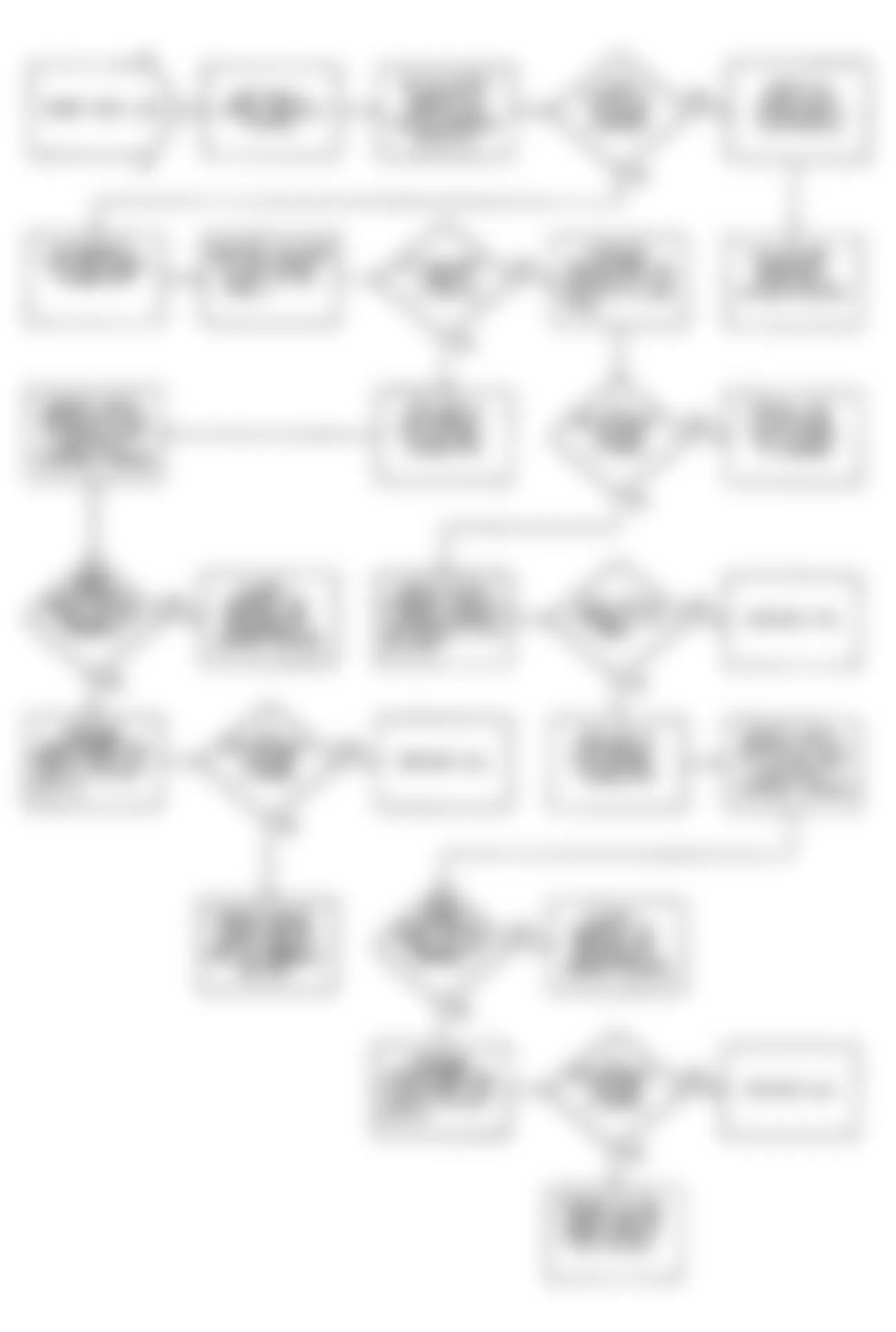
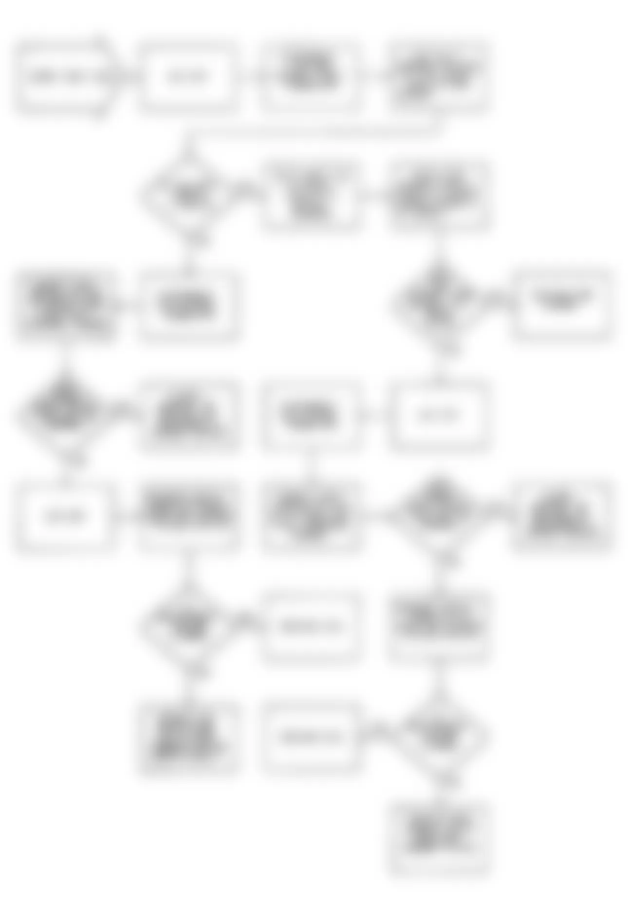
Jeep Wrangler S 1990 - FAULT 1004: ECU BATTERY FEED & POWER GROUNDS
Jeep Wrangler S 1990 - FAULT 1005: SYSTEM GROUND CIRCUIT

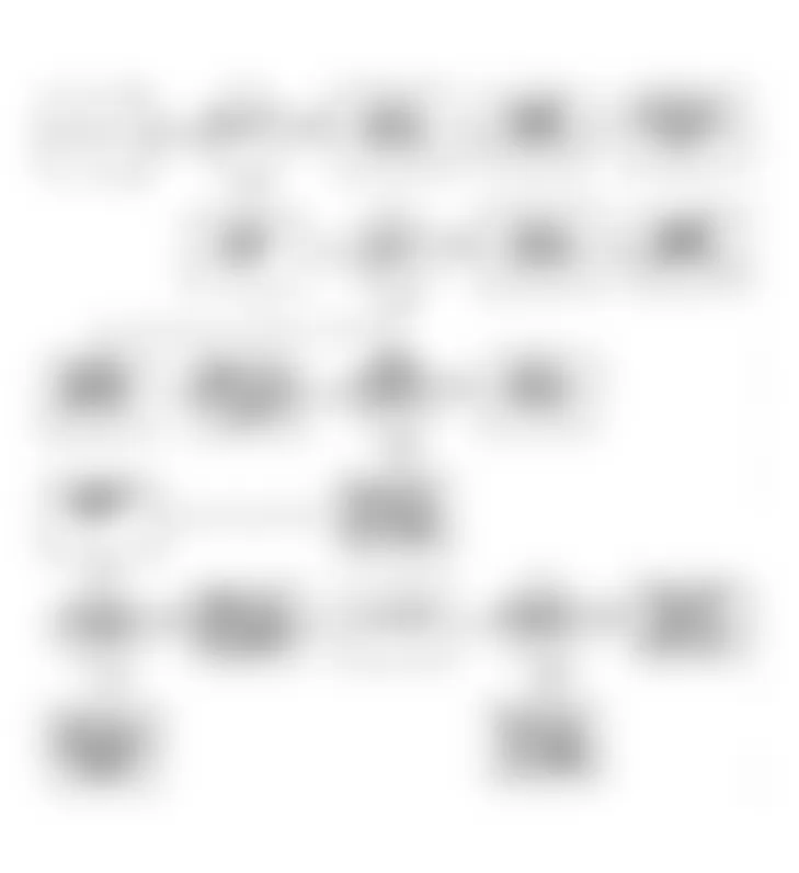
Fig. 12: Jeep Wrangler S 1990 - Component Locations - Fault 1005: Flow Chart System Ground Circuit
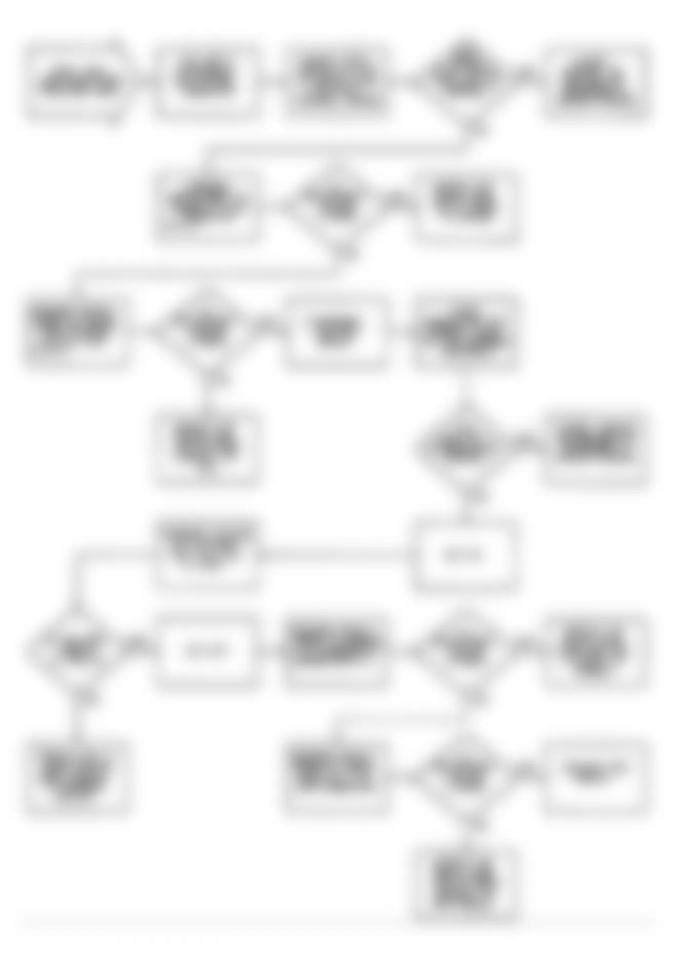
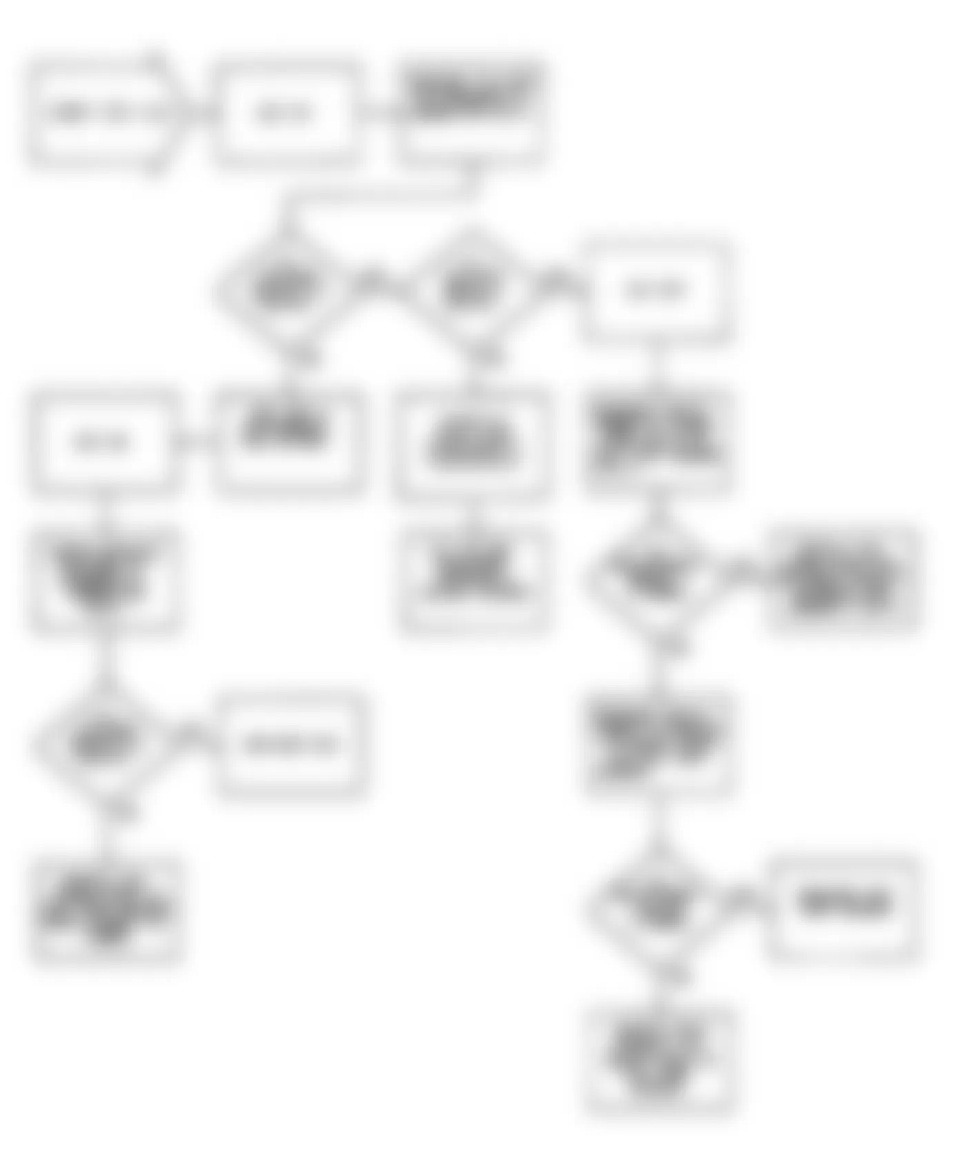
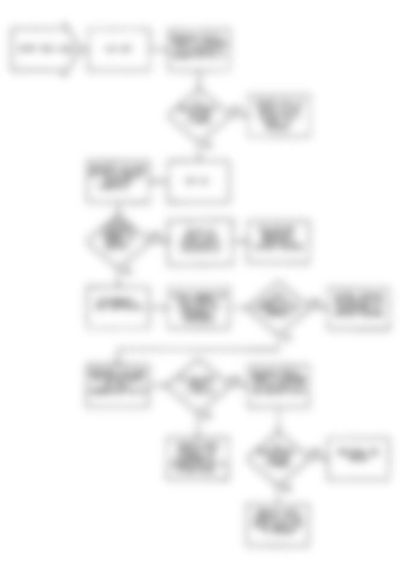
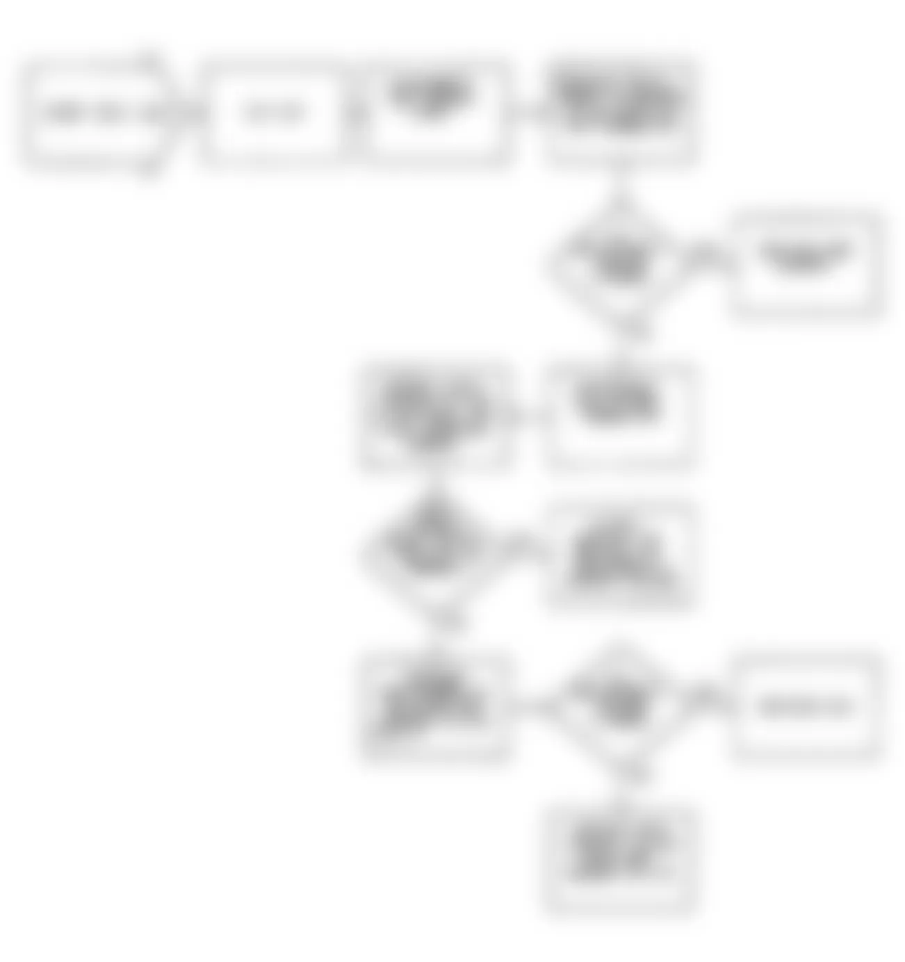
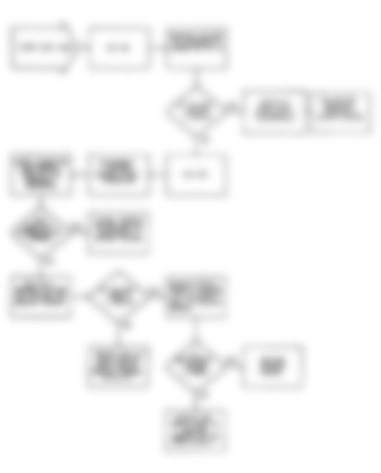
Jeep Wrangler S 1990 - FAULT 1006: EGR SOLENOID CIRCUIT LOW

Jeep Wrangler S 1990 - FAULT 1007: EGR SOLENOID CIRCUIT LOW
Jeep Wrangler S 1990 - FAULT 1008: POWER STEERING CIRCUIT LOW

Jeep Wrangler S 1990 - FAULT 1009: POWER STEERING CIRCUIT HIGH

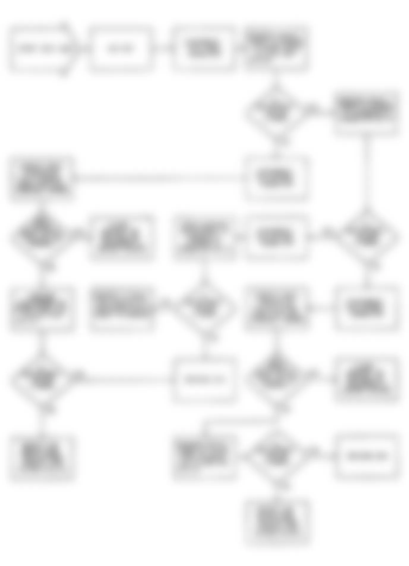
Jeep Wrangler S 1990 - FAULT 1012: FUEL INJECTOR CIRCUITS

Fig. 22: Jeep Wrangler S 1990 - Component Locations - Fault 1012: Flow Chart Fuel Injector Circuits
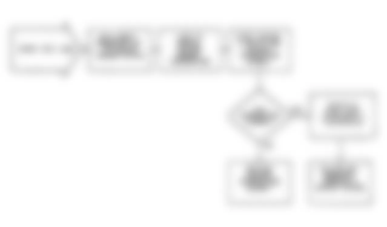
Jeep Wrangler S 1990 - FAULT 1013: IGNITION MODULE (MPA) CIRCUIT HIGH
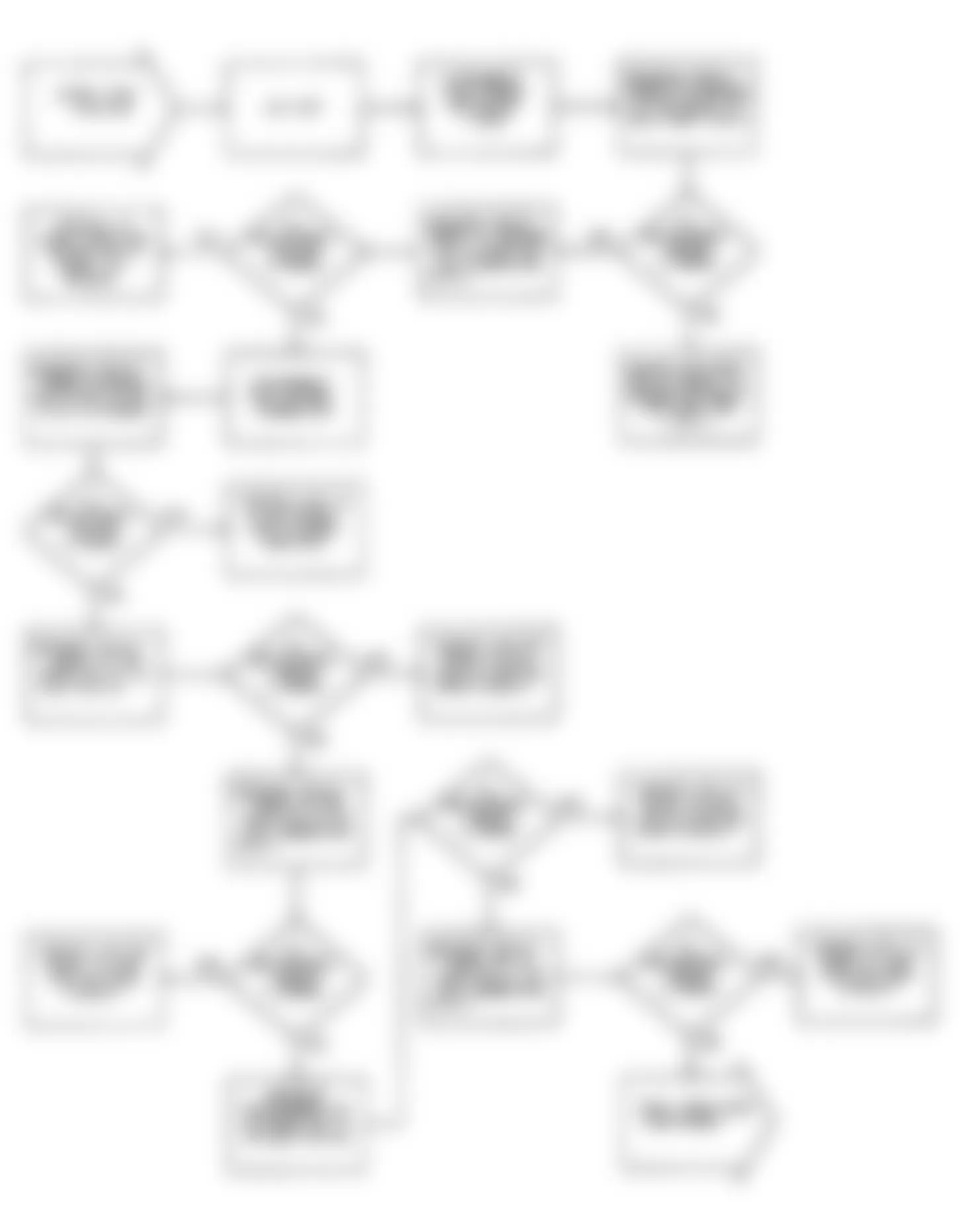
Jeep Wrangler S 1990 - FAULT 1014: FUEL PUMP CIRCUIT LOW

Fig. 26: Jeep Wrangler S 1990 - Component Locations - Fault 1014: Flow Chart Fuel Pump Circuit Low
Jeep Wrangler S 1990 - FAULT 1015: FUEL PUMP CIRCUIT HIGH

Fig. 28: Jeep Wrangler S 1990 - Component Locations - Fault 1015: FLow Chart Fuel Pump Circuit High
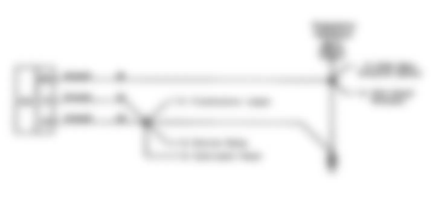
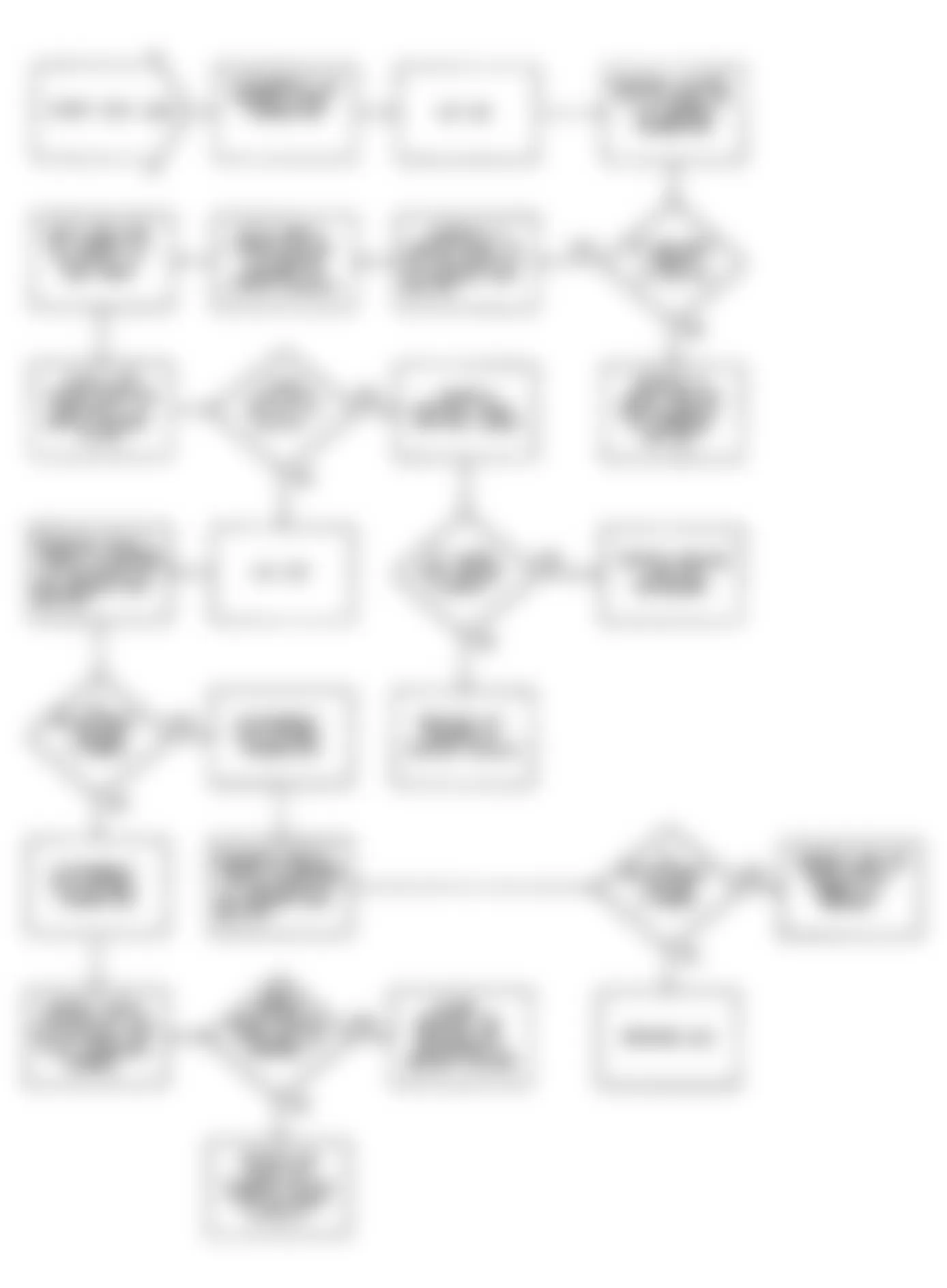
Jeep Wrangler S 1990 - FAULT 1016: MANIFOLD AIR TEMPERATURE (MAT) CIRCUIT LOW
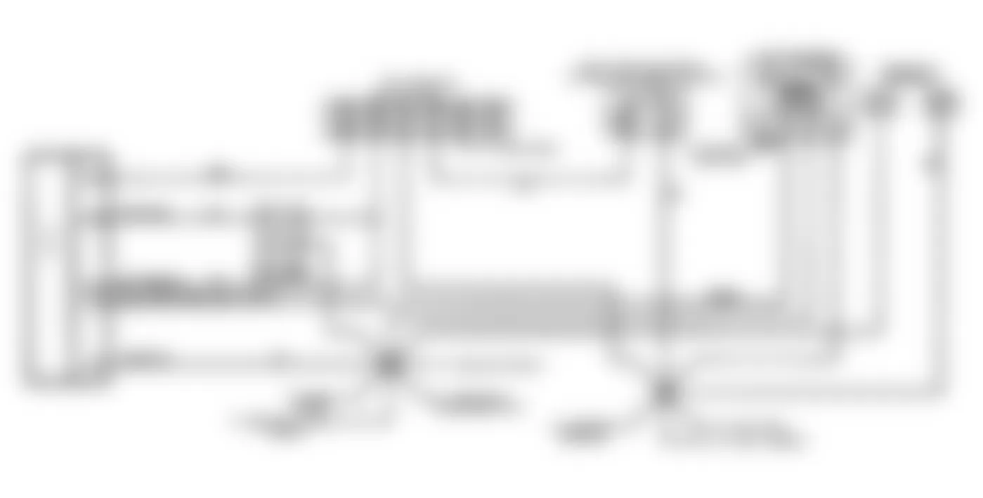
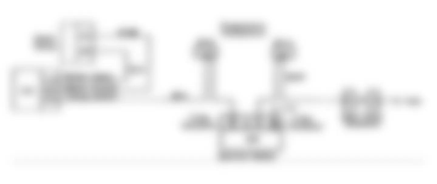
Fig. 29: Jeep Wrangler S 1990 - Component Locations - Fault 1016: Circuit Diagram MAT Circuit Low

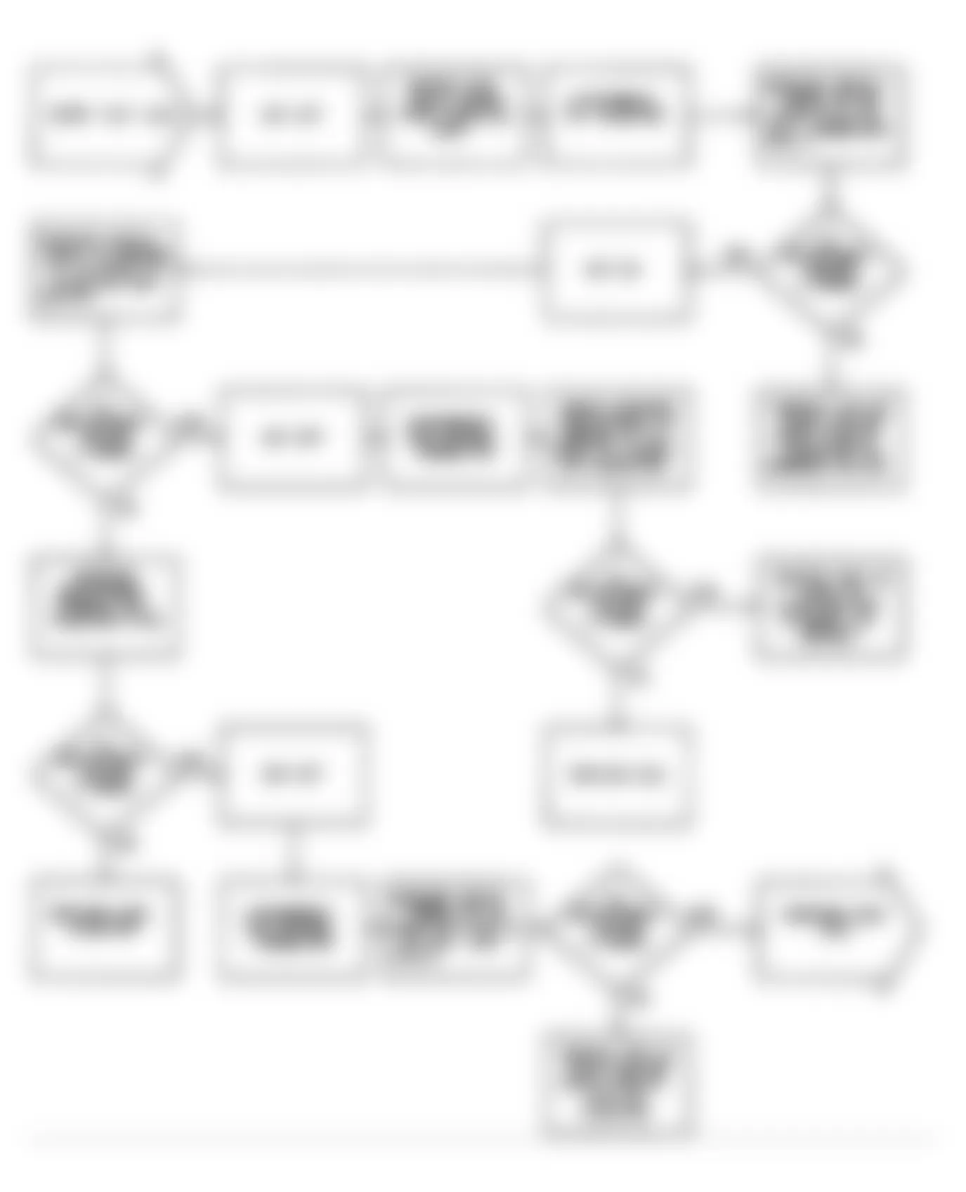
Fig. 30: Jeep Wrangler S 1990 - Component Locations - Fault 1016: Flow Chart MAT Circuit Low
Jeep Wrangler S 1990 - FAULT 1017: MANIFOLD AIR TEMPERATURE (MAT) CIRCUIT HIGH
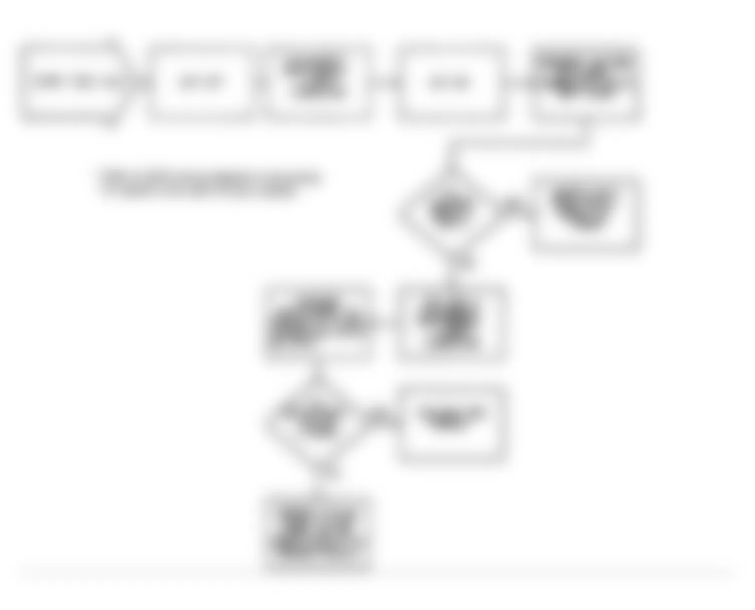
Fig. 31: Jeep Wrangler S 1990 - Component Locations - Fault 1017: Circuit Diagram MAT Circuit High

Fig. 32: Jeep Wrangler S 1990 - Component Locations - Fault 1017: Flow Chart MAT Circuit High
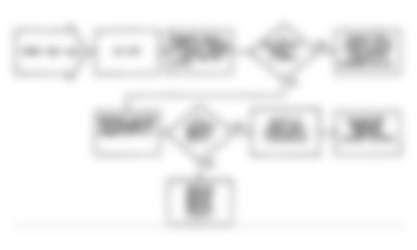
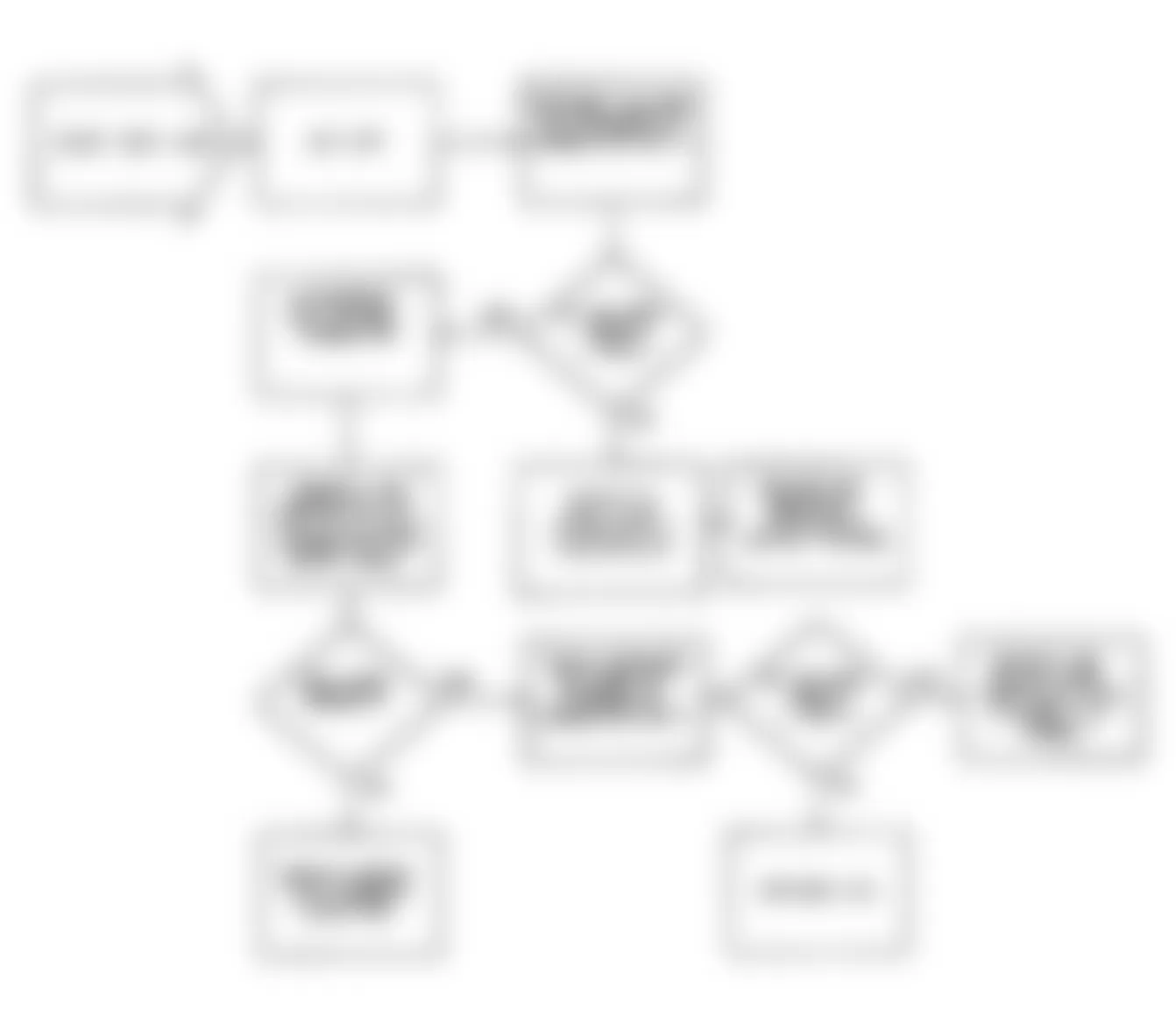
Jeep Wrangler S 1990 - FAULT 1018: SERIAL DATA CIRCUIT
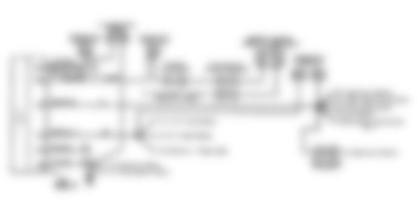
Fig. 34: Jeep Wrangler S 1990 - Component Locations - Fault 1018: Flow Chart Serial Data Circuit
Jeep Wrangler S 1990 - FAULT 1019: POWER LATCH NOT SET
Fig. 35: Jeep Wrangler S 1990 - Component Locations - Fault 1019: Flow Chart Power Latch Not Set
Jeep Wrangler S 1990 - FAULT 1021: ENGINE FAILED TO START

Jeep Wrangler S 1990 - FAULT 1022: STARTER RELAY CIRCUIT LOW

Jeep Wrangler S 1990 - FAULT 1024: NO START SIGNAL AT ECU

Fig. 42: Jeep Wrangler S 1990 - Component Locations - Fault 1024: Flow Chart No Start Signal At ECU
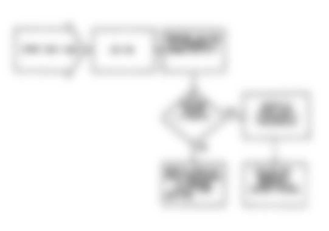
Jeep Wrangler S 1990 - FAULT 1025: WIDE OPEN THROTTLE (WOT) CIRCUIT LOW

Jeep Wrangler S 1990 - FAULT 1027: INJECTOR CONTROL CIRCUIT LOW

Jeep Wrangler S 1990 - FAULT 1028: WIDE OPEN THROTTLE (WOT) CIRCUIT LOW
Fig. 47: Jeep Wrangler S 1990 - Component Locations - Fault 1028: Circuit Diagram WOT Circuit Low

Fig. 48: Jeep Wrangler S 1990 - Component Locations - Fault 1028: Flow Chart WOT Circuit Low
Jeep Wrangler S 1990 - FAULT 1029: IDLE SPEED ACTUATOR (ISA) CLOSED THROTTLE CIRCUIT LOW

Jeep Wrangler S 1990 - FAULT 1030: IDLE SPEED ACTUATOR (ISA) CLOSED THROTTLE CIRCUIT HIGH

Jeep Wrangler S 1990 - FAULT 1031: ECU CLOSED THROTTLE CIRCUIT LOW

Jeep Wrangler S 1990 - FAULT 1032: ECU CLOSED THROTTLE CIRCUIT HIGH
Jeep Wrangler S 1990 - FAULT 1033-36: IDLE SPEED ACTUATOR (ISA) CIRCUITS
Fig. 57: Jeep Wrangler S 1990 - Component Locations - Fault 1033-36: Circuit Diagram ISA Circuits

Jeep Wrangler S 1990 - FAULT 1037: THROTTLE POSITION SENSOR (TPS) CIRCUIT LOW
Fig. 60: Jeep Wrangler S 1990 - Component Locations - Fault 1037: Circuit Diagram TPS Circuit Low

Fig. 61: Jeep Wrangler S 1990 - Component Locations - Fault 1037: Flow Chart TPS Circuit Low
Jeep Wrangler S 1990 - FAULT 1038: SERIAL DATA ENABLE CIRCUIT HIGH
Jeep Wrangler S 1990 - FAULT 1039: SERIAL DATA ENABLE CIRCUIT LOW

Jeep Wrangler S 1990 - FAULT 1040: POWER LATCH RELAY CIRCUIT LOW
Jeep Wrangler S 1990 - FAULT 1041: POWER LATCH RELAY CIRCUIT HIGH

Jeep Wrangler S 1990 - FAULT 1042: CHARGING & ECU CIRCUITS
Fig. 70: Jeep Wrangler S 1990 - Component Locations - Fault 1042: Flow Chart Charging & ECU Circuits

Jeep Wrangler S 1990 - FAULT 1043: SHIFT LIGHT CIRCUIT LOW

Fig. 72: Jeep Wrangler S 1990 - Component Locations - Fault 1043: Flow Chart Shift Light Circuit Low
Jeep Wrangler S 1990 - FAULT 1044: SHIFT LIGHT CIRCUIT HIGH

Jeep Wrangler S 1990 - FAULT 1048: CHECKING M/T VEHICLE FOR CORRECT ECU
Jeep Wrangler S 1990 - FAULT 1050: IDLE RPM LOW
Fig. 76: Jeep Wrangler S 1990 - Component Locations - Fault 1050: Circuit Diagram Idle RPM Low
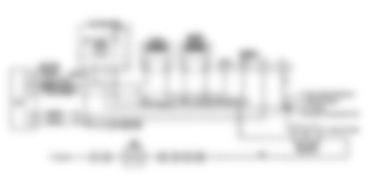
Fig. 77: Jeep Wrangler S 1990 - Component Locations - Fault 1050: Flow Chart Idle RPM Low
Jeep Wrangler S 1990 - FAULT 1051: IDLE RPM HIGH
Fig. 78: Jeep Wrangler S 1990 - Component Locations - Fault 1051: Circuit Diagram Idle RPM High

Fig. 79: Jeep Wrangler S 1990 - Component Locations - Fault 1051: Flow Chart Idle RPM High
Jeep Wrangler S 1990 - FAULT 1052: MAP SENSOR CIRCUIT
Fig. 80: Jeep Wrangler S 1990 - Component Locations - Fault 1052: Circuit Diagram MAP Sensor Circuit

Fig. 81: Jeep Wrangler S 1990 - Component Locations - Fault 1052: Flow Chart MAP Sensor Circuit
Jeep Wrangler S 1990 - FAULT 1053: MAP SENSOR GROUND CIRCUIT

Jeep Wrangler S 1990 - FAULT 1054: COOLANT SENSOR & 5-VOLT SUPPLY TO TPS/MAP CIRCUIT LOW

Jeep Wrangler S 1990 - FAULT 1055: COOLANT SENSOR CIRCUIT HIGH

Jeep Wrangler S 1990 - FAULT 1056: INACTIVE COOLANT TEMPERATURE SENSOR
Jeep Wrangler S 1990 - FAULT 1065: LEAN O2 SENSOR INPUT
NOTE: For additional oxygen sensor information, see TITANIA OXYGEN SENSOR TESTING article.

Fig. 90: Jeep Wrangler S 1990 - Component Locations - Fault 1065: Flow Chart Lean O2 Sensor Input
Jeep Wrangler S 1990 - FAULT 1066: RICH O2 SENSOR INPUT
NOTE: For additional oxygen sensor information, see TITANIA OXYGEN SENSOR TESTING article.

Fig. 92: Jeep Wrangler S 1990 - Component Locations - Fault 1066: Flow Chart Rich O2 Sensor Input
Jeep Wrangler S 1990 - FAULT 1067: LATCH RELAY CIRCUIT LOW

Fig. 94: Jeep Wrangler S 1990 - Component Locations - Fault 1067: Flow Chart Latch Relay Circuit Low