ENGINE PERFORMANCE
4.2L
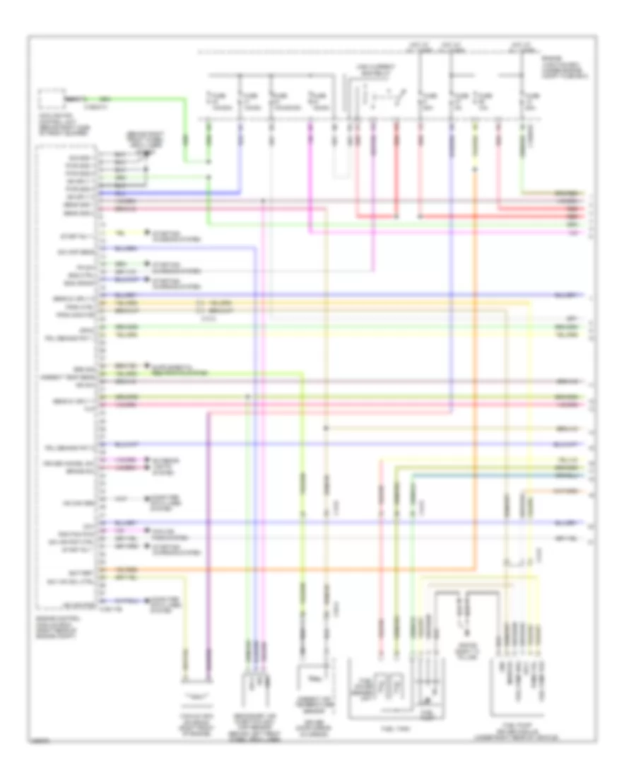
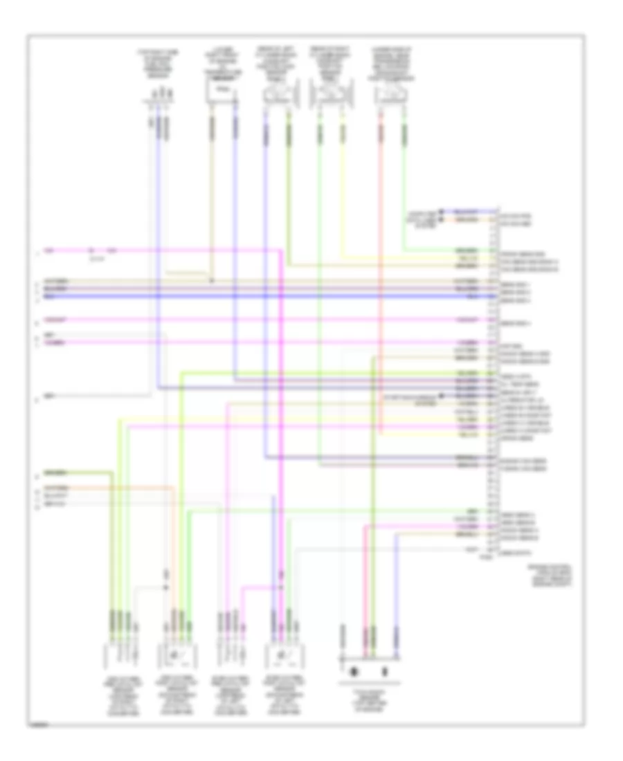
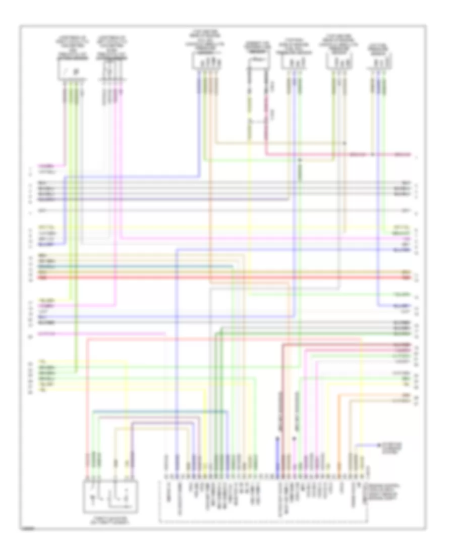
4.2L, Engine Performance Wiring Diagram (1 of 5) for Jaguar XF 2010
 https://portal-diagnostov.com/license.html
Automotive Electricians Portal FZCO
Automotive Electricians Portal FZCO
https://portal-diagnostov.com/license.html
https://portal-diagnostov.com/license.html
Automotive Electricians Portal FZCO
Automotive Electricians Portal FZCO
List of elements for 4.2L, Engine Performance Wiring Diagram (1 of 5) for Jaguar XF 2010:
- (behind right front wheel arch liner) g1d108
- Ambient air temperature sensor
- Ambient temp sens
- Battery
- Brake sw
- C13-a
- C13-e
- C1bb01b
- C1e117b
- C1ec01a
- C3a-a
- C44-e
- Computer data lines system
- Cooling fan control unit (behind right side of front bumper)
- Cooling fans system
- Cov
- Cruise cancel sw
- Dphc
- Driver door mirror (in mirror)
- Ems ctrl
- Eng crank
- Engine control module (ecm) (right rear of engine compt)
- Engine junction box (under engine compt fuse box)
- Exterior lights system
- Flp
- Fpdm ctrl
- Fpdm monitor
- Fuel gauge sender unit
- Fuel pump
- Fuel pump driver module (under right rear of vehicle)
- Fuel pump pos
- Fuel tank
- Fuse 10a
- Fuse 10a/30a
- Fuse 10a/30a/5a
- Fuse 10a/5a
- Fuse 15a/5a
- Fuse 50a
- Fuse 5a
- G3d162 (right "c" pillar)
- Gnd
- High current ems relay
- Hot at all times
- Hs can pos
- Ign sply 1
- Ign sply 2
- Ign sw
- Monitor
- Nca
- Pdl demand pot 1
- Pdl demand pot 2
- Pn sw
- Pwm ctrl
- Pwr gnd 1
- Pwr gnd 2
- Pwr gnd 3
- Ran fan pwm
- Red
- Sai air pmp ctrl
- Sai map sens
- Sai vac sol ctrl
- Secondary air injection (sai) map sensor (behind left front wheel arch liner)
- Sens 5v sply 1
- Sens 5v sply 2
- Sens gnd 1
- Sens gnd 2
- Sig
- Sig gnd 1
- Sply
- Srs sig
- Start rly +
- Start rly -
- Starting/ charging system
- Vacuum (sai) solenoid (right front of engine)
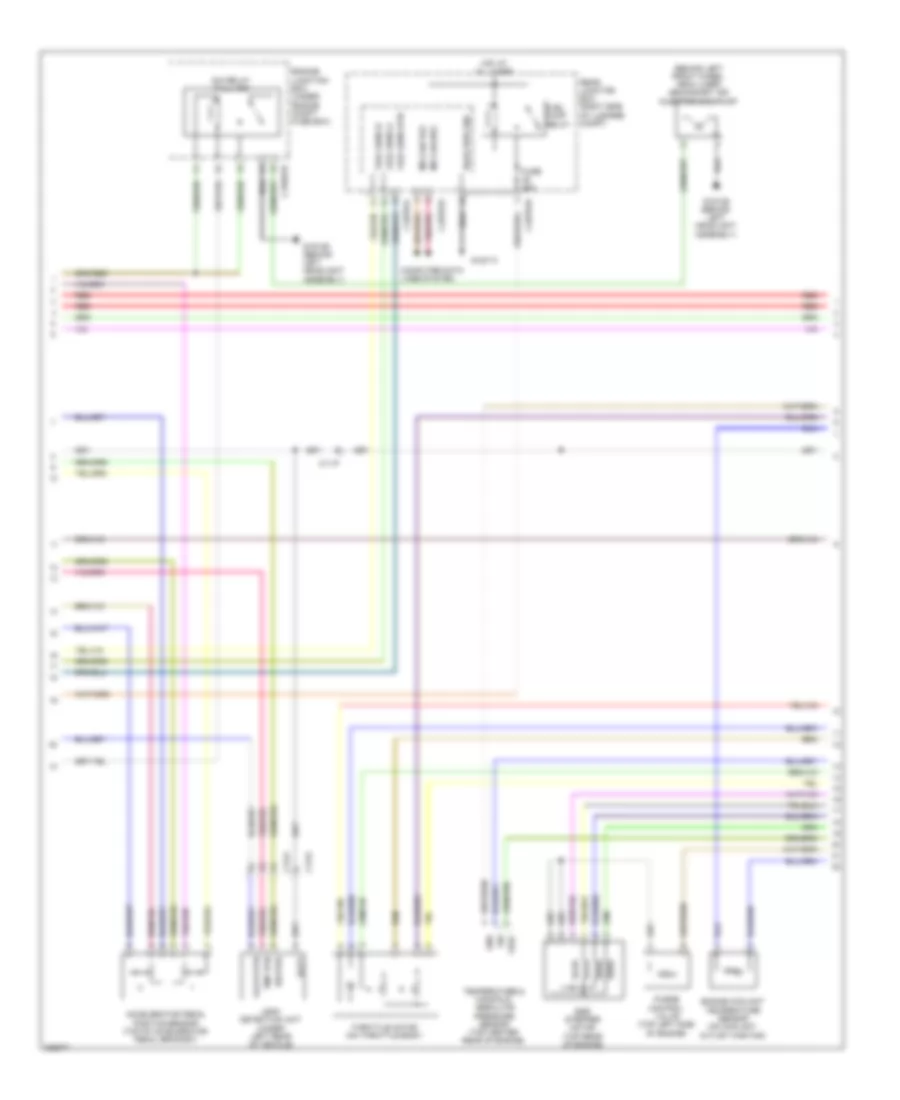
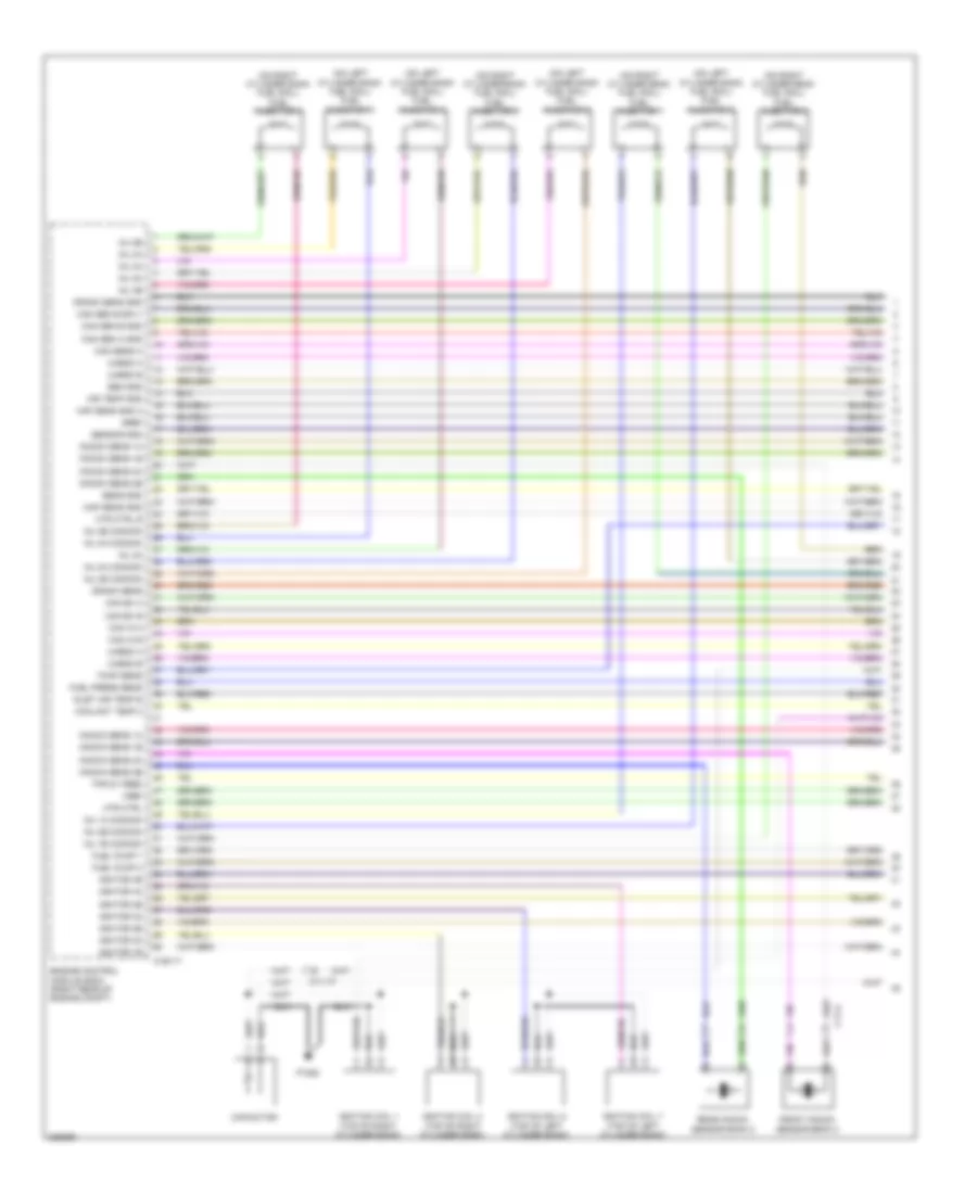
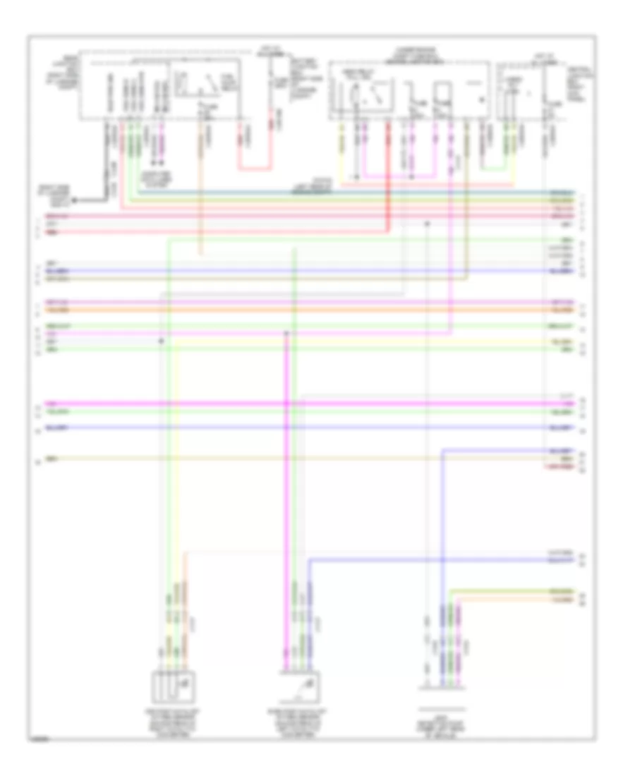
4.2L, Engine Performance Wiring Diagram (2 of 5) for Jaguar XF 2010
 https://portal-diagnostov.com/license.html
Automotive Electricians Portal FZCO
Automotive Electricians Portal FZCO
https://portal-diagnostov.com/license.html
https://portal-diagnostov.com/license.html
Automotive Electricians Portal FZCO
Automotive Electricians Portal FZCOList of elements for 4.2L, Engine Performance Wiring Diagram (2 of 5) for Jaguar XF 2010:
- (behind left front wheel arch liner) secondary air injection (sai) pump
- Accelerator pedal position sensor (top of accelerator pedal bracket)
- Batt
- C11-p
- C13-a
- C13-d
- C1bb01b
- C4bp01d
- C4bp01k
- C4bp01l
- Computer data lines system
- Egr stepper motor (top rear of engine)
- Engine coolant temperature sensor (on coolant outlet casting)
- Engine junction box (under engine compt fuse box)
- Fuel pump relay
- Fuel sens a
- Fuel sens b
- Fuel sens rtn
- Fuse 25a
- G1d129 (behind left headlight assembly)
- G1d173
- Gnd
- Heater
- Hot at all times
- Leak detection unit (under left rear of vehicle)
- Ms can pos
- Pmp rtn
- Purge control valve (top left side of engine)
- Rear junction box (right side of luggage compt)
- Red
- Rsjb pwr gnd
- Sia relay (full iso)
- Sig
- Temperature & manifold absolute pressure sensor (top center rear of engine)
- Throttle motor (on throttle body)
- Valve rtn
- Vref
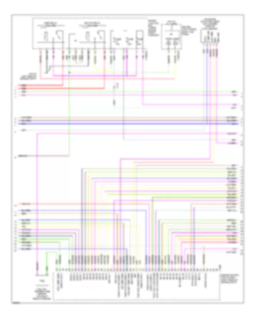
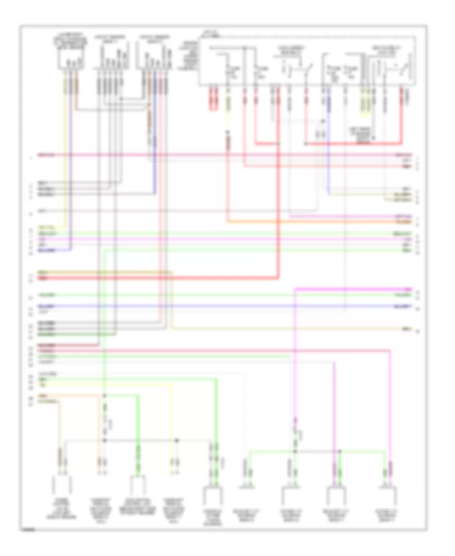
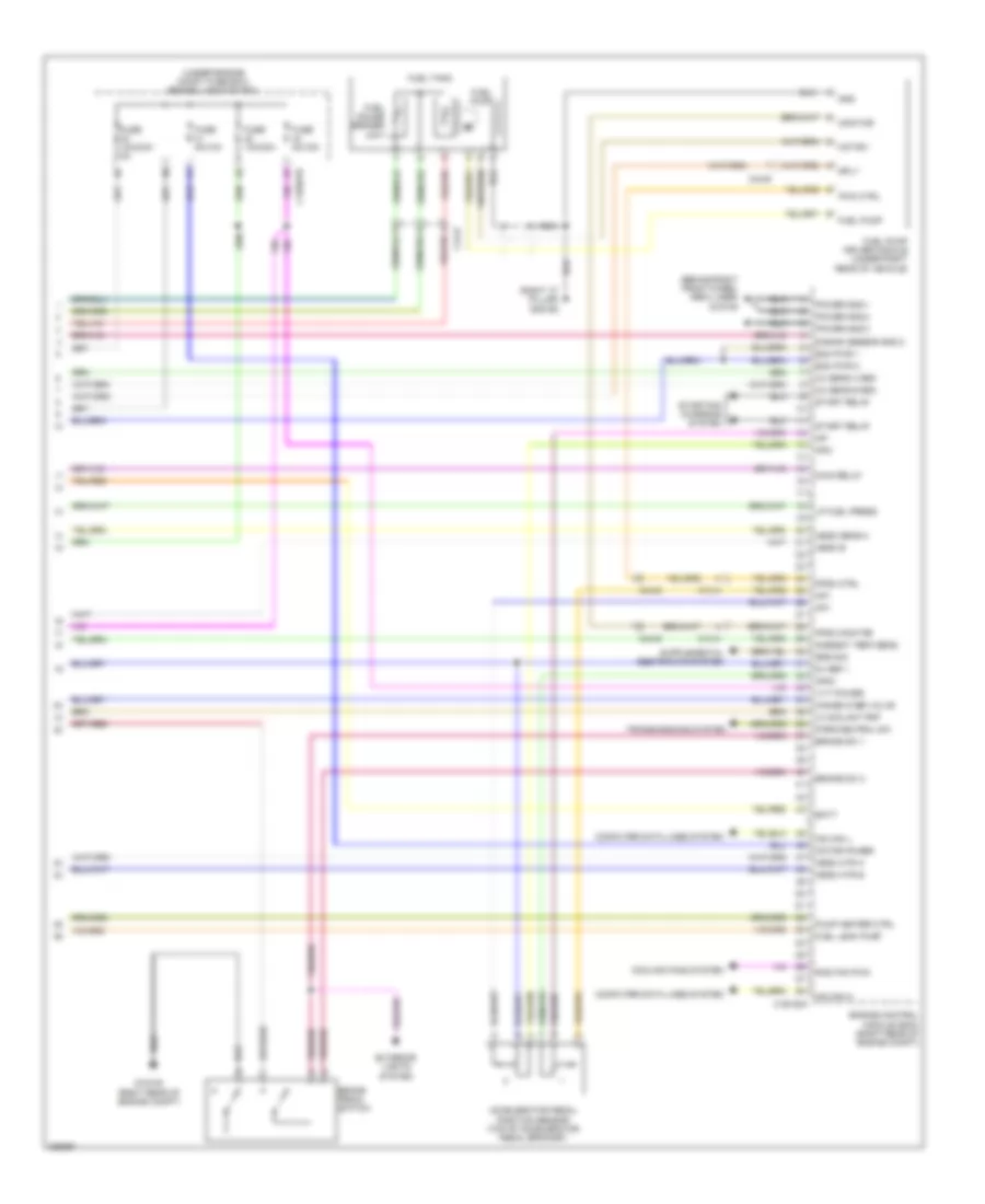
4.2L, Engine Performance Wiring Diagram (3 of 5) for Jaguar XF 2010
 https://portal-diagnostov.com/license.html
Automotive Electricians Portal FZCO
Automotive Electricians Portal FZCO
https://portal-diagnostov.com/license.html
https://portal-diagnostov.com/license.html
Automotive Electricians Portal FZCO
Automotive Electricians Portal FZCOList of elements for 4.2L, Engine Performance Wiring Diagram (3 of 5) for Jaguar XF 2010:
- (on engine air intake, near air cleaner) mass air flow sensor
- Air temp
- Air temp sens
- C11-p
- C1bb01b
- C3bp01h
- Central junction box (right kick panel)
- Coolant temp sens
- Eegr 1
- Eegr 2
- Eegr 3
- Eegr 4
- Engine control module (ecm) (right rear of engine compt)
- Engine junction box (under engine compt fuse box)
- Fpdb ign ctrl
- Fuel rail press sens
- Fuel rail temperature sensor (top right rear of engine)
- Fuel temp sens
- Fuse 15a
- Fuse 20a
- G1d123 (left rear of engine compt)
- Hego relay (full iso)
- Hot at all times
- Htr ctrl a upstream
- Htr ctrl b upstream
- Htr hego a
- Htr hego b
- Ign 1a
- Ign 1b
- Ign 2a
- Ign 2b
- Ign 3a
- Ign 3b
- Ign 4a
- Ign 4b
- Ign fail 1
- Ign fail 2
- Ignition relay (full iso)
- Imtv b
- Inj 1a
- Inj 1b
- Inj 2a
- Inj 2b
- Inj 3a
- Inj 3b
- Inj 4a imtv a
- Inj 4b
- Maf
- Maf gnd
- Map sens
- P1300
- Purge valve
- Red
- Sens 5v sply
- Sply
- Temp gnd
- Throttle mtr +
- Throttle mtr -
- Throttle pos sens 1
- Throttle pos sens 2
- Uhego rly ctrl
- Vvt a
- Vvt b
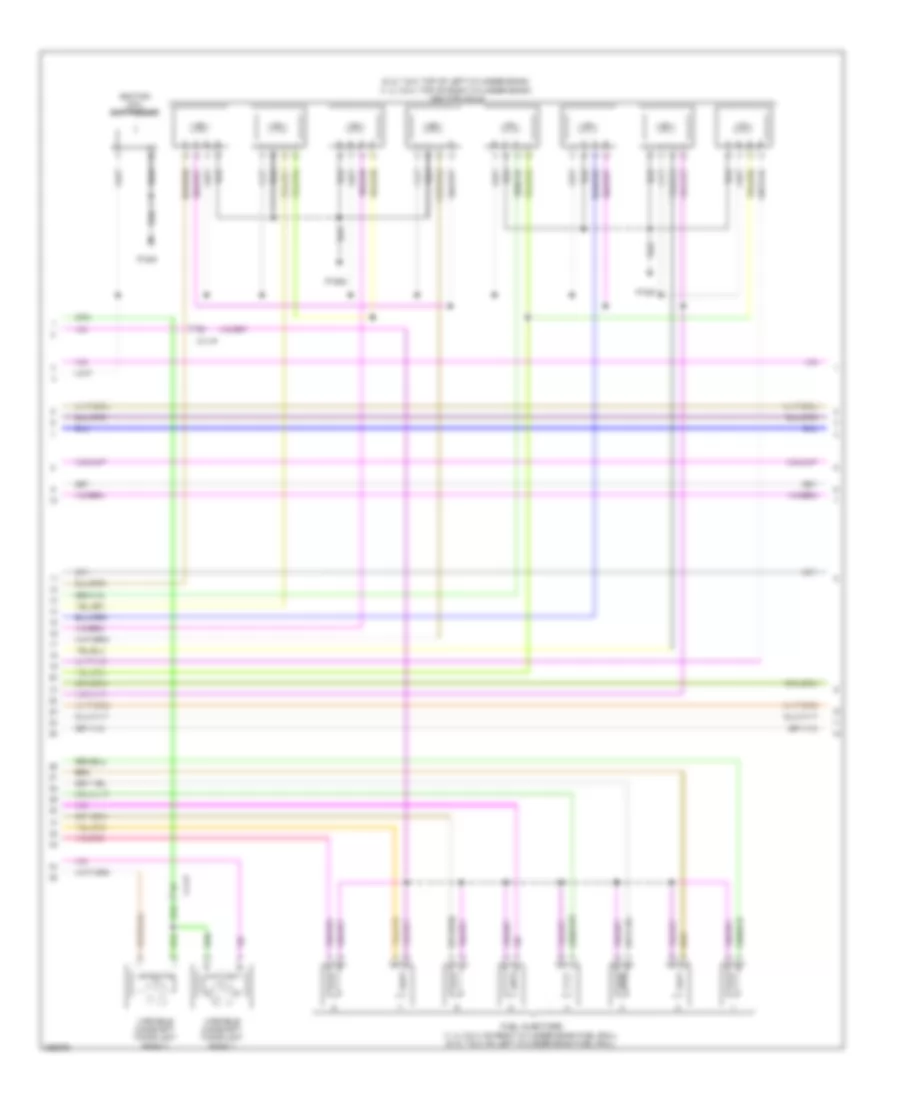
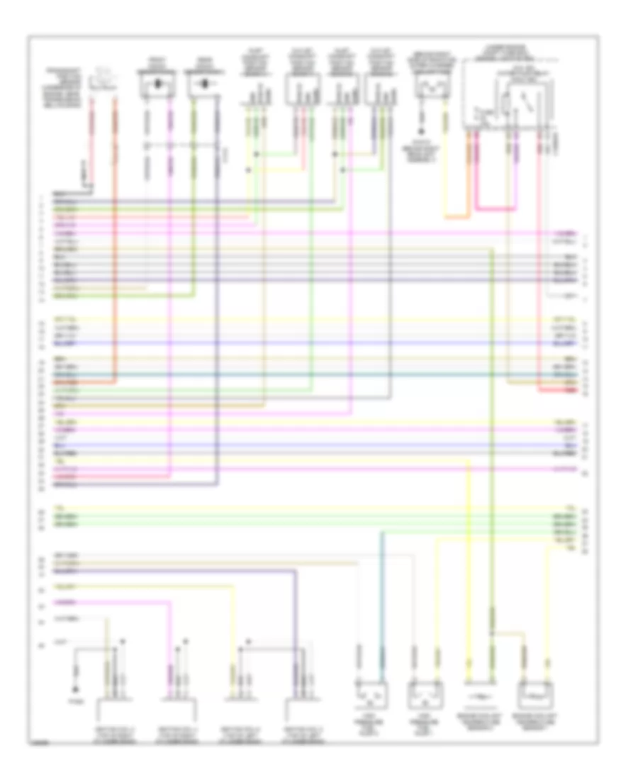
4.2L, Engine Performance Wiring Diagram (4 of 5) for Jaguar XF 2010
 https://portal-diagnostov.com/license.html
Automotive Electricians Portal FZCO
Automotive Electricians Portal FZCO
https://portal-diagnostov.com/license.html
https://portal-diagnostov.com/license.html
Automotive Electricians Portal FZCO
Automotive Electricians Portal FZCOList of elements for 4.2L, Engine Performance Wiring Diagram (4 of 5) for Jaguar XF 2010:
- (5, 6, 7 & 8: top of left cylinder bank) (1, 2, 3 & 4: top of right cylinder bank) ignition coils
- C11-p
- Fuel injectors (1, 2, 3 & 4: on right cylinder bank fuel rail) (5, 6, 7 & 8: on left cylinder bank fuel rail)
- Ignition coil suppressor
- P1051
- P1052
- Variable camshaft timing unit bank 1
- Variable camshaft timing unit bank 2
4.2L, Engine Performance Wiring Diagram (5 of 5) for Jaguar XF 2010
 https://portal-diagnostov.com/license.html
Automotive Electricians Portal FZCO
Automotive Electricians Portal FZCO
https://portal-diagnostov.com/license.html
https://portal-diagnostov.com/license.html
Automotive Electricians Portal FZCO
Automotive Electricians Portal FZCOList of elements for 4.2L, Engine Performance Wiring Diagram (5 of 5) for Jaguar XF 2010:
- (lower right front of engine) oil temperature sensor
- (rear of left cylinder bank)
- (rear of right cylinder bank) camshaft position sensor bank 1
- (top right side of engine) fuel rail pressure sensor
- (under side of engine, near transmission bellhousing) crankshaft position sensor
- A bank cam sens
- Alternator lin
- B bank cam sens
- C11-p
- Cam sens gnd bank a
- Cam sens gnd bank b
- Camshaft position (cmp) sensor bank 2
- Computer data lines system
- Crank sens
- Crank sens gnd
- Engine control module (ecm) (right rear of engine compt)
- Even oxygen post catalyst sensor (downstream of left catalytic converter)
- Even oxygen pre catalyst sensor (upstream of left catalytic converter)
- Gnd
- Hego a rtn
- Hego b rtn
- Hego sens a
- Hego sens b
- Hs can pos
- Knock sens a
- Knock sens a gnd
- Knock sens b
- Knock sens b gnd
- Maf gnd
- Odd oxygen post catalyst sensor (downstream of right catalytic converter)
- Odd oxygen pre catalyst sensor (upstream of right catalytic converter)
- Oil temp sens
- Pi300
- Sens 5v sply
- Sens gnd 1
- Sens gnd 2
- Sens gnd 3
- Sens gnd 4
- Sig
- Starting/charging system
- Twin knock sensor (top center of engine)
- Uhego a constant
- Uhego a variable
- Uhego b constant
- Uhego b variable
- Vref
5.0L
5.0L, Engine Performance Wiring Diagram (1 of 6) for Jaguar XF 2010
 https://portal-diagnostov.com/license.html
Automotive Electricians Portal FZCO
Automotive Electricians Portal FZCO
https://portal-diagnostov.com/license.html
https://portal-diagnostov.com/license.html
Automotive Electricians Portal FZCO
Automotive Electricians Portal FZCOList of elements for 5.0L, Engine Performance Wiring Diagram (1 of 6) for Jaguar XF 2010:
- (on left cylinder bank fuel rail) fuel injector 5
- (on left cylinder bank fuel rail) fuel injector 6
- (on left cylinder bank fuel rail) fuel injector 7
- (on left cylinder bank fuel rail) fuel injector 8
- (on right cylinder bank fuel rail) fuel injector 1
- (on right cylinder bank fuel rail) fuel injector 2
- (on right cylinder bank fuel rail) fuel injector 3
- (on right cylinder bank fuel rail) fuel injector 4
- Air temp gnd
- C11-a
- C111-p
- C1e117
- Cam ex a
- Cam ex b
- Cam in a
- Cam in b
- Cam sen a gnd
- Cam sen b gnd
- Cam sen b sply
- Cam sens a
- Capacitor
- Coolant temp 2
- Crank sens
- Crank sens gnd
- Engine control module (ecm) (right rear of engine compt)
- Front knock sensor bank 2
- Fuel press sens
- Fuel pump 1
- Fuel pump 2
- Gref
- Htr ctrl
- Htr ctrl b
- Ignition coil 1 (top of right cylinder bank)
- Ignition coil 3 (top of right cylinder bank)
- Ignition coil 5 (top of left cylinder bank)
- Ignition coil 7 (top of left cylinder bank)
- Ignitor 1b
- Ignitor 2a
- Ignitor 2b
- Ignitor 3a
- Ignitor 3b
- Ignitor 4a
- Ignitor 4b
- Inj 1a commom
- Inj 1b commom
- Inj 2a
- Inj 2a commom
- Inj 2b
- Inj 2b common
- Inj 3a
- Inj 3b common
- Inj 4a
- Inj 4a common
- Inj 4b
- Inj 4b common
- Inlet air temp b
- Knock sens 1a
- Knock sens 1b
- Knock sens 2a
- Knock sens 2b
- Maf sens gnd a
- Map sens gnd
- P1080
- Rear knock sensor bank 2
- Sen gnd
- Sens gnd
- Sensor gnd
- Tmap sens
- Tps 5v feed
- Uhego a
- Uhego b
- Vref
5.0L, Engine Performance Wiring Diagram (2 of 6) for Jaguar XF 2010
 https://portal-diagnostov.com/license.html
Automotive Electricians Portal FZCO
Automotive Electricians Portal FZCO
https://portal-diagnostov.com/license.html
https://portal-diagnostov.com/license.html
Automotive Electricians Portal FZCO
Automotive Electricians Portal FZCOList of elements for 5.0L, Engine Performance Wiring Diagram (2 of 6) for Jaguar XF 2010:
- (5.0l sc) water pump relay (half iso)
- (behind right side of radiator) super charger coolant pump
- (under engine compt fuse box) engine junction box
- C11-a
- C1bb01b
- Crankshaft position sensor (underside of engine, near transmission bellhousing)
- Engine coolant temperature sensor 1
- Engine coolant temperature sensor 2
- Front knock sensor bank 1
- Fuse 15a
- G1d131 (behind right headlight assembly)
- Gnd
- High pressure fuel pump 1
- High pressure fuel pump 2
- Ignition coil 2 (top of right cylinder bank)
- Ignition coil 4 (top of right cylinder bank)
- Ignition coil 6 (top of left cylinder bank)
- Ignition coil 8 (top of left cylinder bank)
- Inlet camshaft position sensor (bank 1)
- Inlet camshaft position sensor (bank 2)
- Nca
- Outlet camshaft position sensor (bank 1)
- Outlet camshaft position sensor (bank 2)
- P1080
- Pwr 5v
- Rear knock sensor bank 2
- Red
- Sens
5.0L, Engine Performance Wiring Diagram (3 of 6) for Jaguar XF 2010
 https://portal-diagnostov.com/license.html
Automotive Electricians Portal FZCO
Automotive Electricians Portal FZCO
https://portal-diagnostov.com/license.html
https://portal-diagnostov.com/license.html
Automotive Electricians Portal FZCO
Automotive Electricians Portal FZCOList of elements for 5.0L, Engine Performance Wiring Diagram (3 of 6) for Jaguar XF 2010:
- (info not available)
- (top center rear of engine) (5.0l sc) manifold absolute pressure sensor
- (top center rear of engine) manifold absolute pressure sensor
- (top righ side of engine) fuel rail pressure sensor
- (upstream of left catalytic converter) even pre-catalyst oxygen sensor
- (upstream of right catalytic converter) odd pre-catalyst oxygen sensor
- +5v
- Active ext valve
- Ambient air temperature sensor
- C13-e
- C1e117
- C3a-a
- Coolant temp
- Cps a
- Cps b
- E box fan
- Engine control module (ecm) (right rear of engine compt)
- Fuel pump 1
- Fuel pump 2
- Gnd
- Ignitor 1a
- Imtv
- Inj 1b
- Inj 3b
- Injector 1a
- Inlet air temp a
- Lin
- Low fuel pressure sensor
- Maf sensor a
- Maf sensor b
- Map sensor
- Oil quality sens
- Purge valve
- Red
- Sig
- Starting/ charging system
- Temp
- Temp sens
- Throttle +
- Throttle -
- Throttle motor (on throttle body)
- Tps gnd
- Tps1
- Tps2
- Vfs ex b
- Vfs in a
- Vfs in b
- Vfsex a
- Vout
- Vref
5.0L, Engine Performance Wiring Diagram (4 of 6) for Jaguar XF 2010
 https://portal-diagnostov.com/license.html
Automotive Electricians Portal FZCO
Automotive Electricians Portal FZCO
https://portal-diagnostov.com/license.html
https://portal-diagnostov.com/license.html
Automotive Electricians Portal FZCO
Automotive Electricians Portal FZCOList of elements for 5.0L, Engine Performance Wiring Diagram (4 of 6) for Jaguar XF 2010:
- (left rear of engine compt) g1d123
- (lower right front of engine) oil temperature level sensor
- C11-a
- C11-p
- C1bb01b
- Camshaft profile switching solenoid (bank 1) (5.0l)
- Camshaft profile switching solenoid (bank 2) (5.0l)
- Cooling fan control unit (behind right side of front bumper)
- Engine junction box (under engine compt fuse box)
- Exhaust vvt solenoid (bank 1)
- Exhaust vvt solenoid (bank 2)
- Fuse 10a
- Fuse 15a
- Fuse 20a/ 15a
- Fuse 50a
- Gnd
- Gnf
- High current ems relay
- Hot at all times
- Iat gnd
- Iat output
- Ignition relay (half iso)
- Intake vvt solenoid (bank 1)
- Intake vvt solenoid (bank 2)
- Maf sens
- Maf/iat sensor (bank 1)
- Maf/iat sensor (bank 2)
- Manifold intake tuning solenoid
- Purge control valve (top left side of engine)
- Pwr
- Red
- Sig
- Vref
5.0L, Engine Performance Wiring Diagram (5 of 6) for Jaguar XF 2010
 https://portal-diagnostov.com/license.html
Automotive Electricians Portal FZCO
Automotive Electricians Portal FZCO
https://portal-diagnostov.com/license.html
https://portal-diagnostov.com/license.html
Automotive Electricians Portal FZCO
Automotive Electricians Portal FZCOList of elements for 5.0L, Engine Performance Wiring Diagram (5 of 6) for Jaguar XF 2010:
- (right side of luggage compt) g4d173
- (under engine compt fuse box) engine junction box
- Battery junction box (right side of luggage compt)
- C11-p
- C13-a
- C13-d
- C1bb01b
- C3bp01f
- C3bp01h
- C44-m
- C44-n
- C4bf10b
- C4bp01a
- C4bp01d
- C4bp01l
- Central junction box (right kick panel)
- Computer data lines system
- Even post-catalyst oxygen sensor (downstream of left catalytic converter)
- Fuel pump relay
- Fuel sens a
- Fuel sens b
- Fuel sens rtn
- Fuse 20a
- Fuse 250a
- Fuse 25a
- Fuse 5a
- G1d123 (left rear of engine compt)
- Hego relay (full iso)
- Hot at all times
- Leak detection pump (under left rear of vehicle)
- Ms can pos
- Odd post-catalyst oxygen sensor (downstream of right catalytic converter)
- Rear junction box (right side of luggage compt)
- Red
- Rsjb pwr gnd
- Uhego rly ctrl
5.0L, Engine Performance Wiring Diagram (6 of 6) for Jaguar XF 2010
 https://portal-diagnostov.com/license.html
Automotive Electricians Portal FZCO
Automotive Electricians Portal FZCO
https://portal-diagnostov.com/license.html
https://portal-diagnostov.com/license.html
Automotive Electricians Portal FZCO
Automotive Electricians Portal FZCOList of elements for 5.0L, Engine Performance Wiring Diagram (6 of 6) for Jaguar XF 2010:
- (behind right front wheel arch liner) g1d108
- (right "c" pillar) g3d162
- (under engine compt fuse box) engine junction box
- 5v ref 1
- Accelerator pedal position sensor (top of accelerator pedal bracket)
- Ambient temp sens
- Ap-
- Ap1
- Ap2-
- Ap5v
- B bank sensor gnd 2
- Batt
- Brake pedal switch
- Brake sw 1
- Brake sw 2
- C13-a
- C1bb01b
- C1e120a
- C44-e
- Computer data lines system
- Cooling fans system
- Ecm pwr 1
- Ecm pwr 2
- Engine control module (ecm) (right rear of engine compt)
- Exterior lights system
- Fpdm ctrl
- Fpdm monitor
- Fuel gauge sender unit
- Fuel leak pump
- Fuel pump
- Fuel pump driver module (under right rear of vehicle)
- Fuel tank
- Fuse 10a/30a
- Fuse 10a/30a/ 5a
- Fuse 5a/10a
- Fuse 5a/15a
- G1d120 (right rear of engine compt)
- Gnd
- Hange over valve
- Hego b
- Hego htr a
- Hego htr b
- Hego sens a
- Hs can h
- Hs can l
- Ic coolant pmp
- Lp fuel press
- Main relay
- Monitor
- Motor -
- Motor power
- Nca
- Ox sens a gnd
- Ox sens b gnd
- Park/neutral sw
- Power gnd 1
- Power gnd 2
- Power gnd 3
- Pump heater ctrl
- Pwm ctrl
- Rad fan pwm
- Sply
- Srs sig
- Start relay
- Starting/ charging system
- Transmissions system
- Vvt power
5.0L SC
5.0L SC, Engine Performance Wiring Diagram (1 of 6) for Jaguar XF 2010
 https://portal-diagnostov.com/license.html
Automotive Electricians Portal FZCO
Automotive Electricians Portal FZCO
https://portal-diagnostov.com/license.html
https://portal-diagnostov.com/license.html
Automotive Electricians Portal FZCO
Automotive Electricians Portal FZCOList of elements for 5.0L SC, Engine Performance Wiring Diagram (1 of 6) for Jaguar XF 2010:
- (on left cylinder bank fuel rail) fuel injector 5
- (on left cylinder bank fuel rail) fuel injector 6
- (on left cylinder bank fuel rail) fuel injector 7
- (on left cylinder bank fuel rail) fuel injector 8
- (on right cylinder bank fuel rail) fuel injector 1
- (on right cylinder bank fuel rail) fuel injector 2
- (on right cylinder bank fuel rail) fuel injector 3
- (on right cylinder bank fuel rail) fuel injector 4
- Air temp gnd
- C11-a
- C111-p
- C1e117
- Cam ex a
- Cam ex b
- Cam in a
- Cam in b
- Cam sen a gnd
- Cam sen b gnd
- Cam sen b sply
- Cam sens a
- Capacitor
- Coolant temp 2
- Crank sens
- Crank sens gnd
- Engine control module (ecm) (right rear of engine compt)
- Front knock sensor bank 2
- Fuel press sens
- Fuel pump 1
- Fuel pump 2
- Gref
- Htr ctrl
- Htr ctrl b
- Ignition coil 1 (top of right cylinder bank)
- Ignition coil 3 (top of right cylinder bank)
- Ignition coil 5 (top of left cylinder bank)
- Ignition coil 7 (top of left cylinder bank)
- Ignitor 1b
- Ignitor 2a
- Ignitor 2b
- Ignitor 3a
- Ignitor 3b
- Ignitor 4a
- Ignitor 4b
- Inj 1a commom
- Inj 1b commom
- Inj 2a
- Inj 2a commom
- Inj 2b
- Inj 2b common
- Inj 3a
- Inj 3b common
- Inj 4a
- Inj 4a common
- Inj 4b
- Inj 4b common
- Inlet air temp b
- Knock sens 1a
- Knock sens 1b
- Knock sens 2a
- Knock sens 2b
- Maf sens gnd a
- Map sens gnd
- P1080
- Rear knock sensor bank 2
- Sen gnd
- Sens gnd
- Sensor gnd
- Tmap sens
- Tps 5v feed
- Uhego a
- Uhego b
- Vref
5.0L SC, Engine Performance Wiring Diagram (2 of 6) for Jaguar XF 2010
 https://portal-diagnostov.com/license.html
Automotive Electricians Portal FZCO
Automotive Electricians Portal FZCO
https://portal-diagnostov.com/license.html
https://portal-diagnostov.com/license.html
Automotive Electricians Portal FZCO
Automotive Electricians Portal FZCOList of elements for 5.0L SC, Engine Performance Wiring Diagram (2 of 6) for Jaguar XF 2010:
- (5.0l sc) water pump relay (half iso)
- (behind right side of radiator) super charger coolant pump
- (under engine compt fuse box) engine junction box
- C11-a
- C1bb01b
- Crankshaft position sensor (underside of engine, near transmission bellhousing)
- Engine coolant temperature sensor 1
- Engine coolant temperature sensor 2
- Front knock sensor bank 1
- Fuse 15a
- G1d131 (behind right headlight assembly)
- Gnd
- High pressure fuel pump 1
- High pressure fuel pump 2
- Ignition coil 2 (top of right cylinder bank)
- Ignition coil 4 (top of right cylinder bank)
- Ignition coil 6 (top of left cylinder bank)
- Ignition coil 8 (top of left cylinder bank)
- Inlet camshaft position sensor (bank 1)
- Inlet camshaft position sensor (bank 2)
- Nca
- Outlet camshaft position sensor (bank 1)
- Outlet camshaft position sensor (bank 2)
- P1080
- Pwr 5v
- Rear knock sensor bank 2
- Red
- Sens
5.0L SC, Engine Performance Wiring Diagram (3 of 6) for Jaguar XF 2010
 https://portal-diagnostov.com/license.html
Automotive Electricians Portal FZCO
Automotive Electricians Portal FZCO
https://portal-diagnostov.com/license.html
https://portal-diagnostov.com/license.html
Automotive Electricians Portal FZCO
Automotive Electricians Portal FZCOList of elements for 5.0L SC, Engine Performance Wiring Diagram (3 of 6) for Jaguar XF 2010:
- (info not available)
- (top center rear of engine) (5.0l sc) manifold absolute pressure sensor
- (top center rear of engine) manifold absolute pressure sensor
- (top righ side of engine) fuel rail pressure sensor
- (upstream of left catalytic converter) even pre-catalyst oxygen sensor
- (upstream of right catalytic converter) odd pre-catalyst oxygen sensor
- +5v
- Active ext valve
- Ambient air temperature sensor
- C13-e
- C1e117
- C3a-a
- Coolant temp
- Cps a
- Cps b
- E box fan
- Engine control module (ecm) (right rear of engine compt)
- Fuel pump 1
- Fuel pump 2
- Gnd
- Ignitor 1a
- Imtv
- Inj 1b
- Inj 3b
- Injector 1a
- Inlet air temp a
- Lin
- Low fuel pressure sensor
- Maf sensor a
- Maf sensor b
- Map sensor
- Oil quality sens
- Purge valve
- Red
- Sig
- Starting/ charging system
- Temp
- Temp sens
- Throttle +
- Throttle -
- Throttle motor (on throttle body)
- Tps gnd
- Tps1
- Tps2
- Vfs ex b
- Vfs in a
- Vfs in b
- Vfsex a
- Vout
- Vref
5.0L SC, Engine Performance Wiring Diagram (4 of 6) for Jaguar XF 2010
 https://portal-diagnostov.com/license.html
Automotive Electricians Portal FZCO
Automotive Electricians Portal FZCO
https://portal-diagnostov.com/license.html
https://portal-diagnostov.com/license.html
Automotive Electricians Portal FZCO
Automotive Electricians Portal FZCOList of elements for 5.0L SC, Engine Performance Wiring Diagram (4 of 6) for Jaguar XF 2010:
- (left rear of engine compt) g1d123
- (lower right front of engine) oil temperature level sensor
- C11-a
- C11-p
- C1bb01b
- Camshaft profile switching solenoid (bank 1) (5.0l)
- Camshaft profile switching solenoid (bank 2) (5.0l)
- Cooling fan control unit (behind right side of front bumper)
- Engine junction box (under engine compt fuse box)
- Exhaust vvt solenoid (bank 1)
- Exhaust vvt solenoid (bank 2)
- Fuse 10a
- Fuse 15a
- Fuse 20a/ 15a
- Fuse 50a
- Gnd
- Gnf
- High current ems relay
- Hot at all times
- Iat gnd
- Iat output
- Ignition relay (half iso)
- Intake vvt solenoid (bank 1)
- Intake vvt solenoid (bank 2)
- Maf sens
- Maf/iat sensor (bank 1)
- Maf/iat sensor (bank 2)
- Manifold intake tuning solenoid
- Purge control valve (top left side of engine)
- Pwr
- Red
- Sig
- Vref
5.0L SC, Engine Performance Wiring Diagram (5 of 6) for Jaguar XF 2010
 https://portal-diagnostov.com/license.html
Automotive Electricians Portal FZCO
Automotive Electricians Portal FZCO
https://portal-diagnostov.com/license.html
https://portal-diagnostov.com/license.html
Automotive Electricians Portal FZCO
Automotive Electricians Portal FZCOList of elements for 5.0L SC, Engine Performance Wiring Diagram (5 of 6) for Jaguar XF 2010:
- (right side of luggage compt) g4d173
- (under engine compt fuse box) engine junction box
- Battery junction box (right side of luggage compt)
- C11-p
- C13-a
- C13-d
- C1bb01b
- C3bp01f
- C3bp01h
- C44-m
- C44-n
- C4bf10b
- C4bp01a
- C4bp01d
- C4bp01l
- Central junction box (right kick panel)
- Computer data lines system
- Even post-catalyst oxygen sensor (downstream of left catalytic converter)
- Fuel pump relay
- Fuel sens a
- Fuel sens b
- Fuel sens rtn
- Fuse 20a
- Fuse 250a
- Fuse 25a
- Fuse 5a
- G1d123 (left rear of engine compt)
- Hego relay (full iso)
- Hot at all times
- Leak detection pump (under left rear of vehicle)
- Ms can pos
- Odd post-catalyst oxygen sensor (downstream of right catalytic converter)
- Rear junction box (right side of luggage compt)
- Red
- Rsjb pwr gnd
- Uhego rly ctrl
5.0L SC, Engine Performance Wiring Diagram (6 of 6) for Jaguar XF 2010
 https://portal-diagnostov.com/license.html
Automotive Electricians Portal FZCO
Automotive Electricians Portal FZCO
https://portal-diagnostov.com/license.html
https://portal-diagnostov.com/license.html
Automotive Electricians Portal FZCO
Automotive Electricians Portal FZCOList of elements for 5.0L SC, Engine Performance Wiring Diagram (6 of 6) for Jaguar XF 2010:
- (behind right front wheel arch liner) g1d108
- (right "c" pillar) g3d162
- (under engine compt fuse box) engine junction box
- 5v ref 1
- Accelerator pedal position sensor (top of accelerator pedal bracket)
- Ambient temp sens
- Ap-
- Ap1
- Ap2-
- Ap5v
- B bank sensor gnd 2
- Batt
- Brake pedal switch
- Brake sw 1
- Brake sw 2
- C13-a
- C1bb01b
- C1e120a
- C44-e
- Computer data lines system
- Cooling fans system
- Ecm pwr 1
- Ecm pwr 2
- Engine control module (ecm) (right rear of engine compt)
- Exterior lights system
- Fpdm ctrl
- Fpdm monitor
- Fuel gauge sender unit
- Fuel leak pump
- Fuel pump
- Fuel pump driver module (under right rear of vehicle)
- Fuel tank
- Fuse 10a/30a
- Fuse 10a/30a/ 5a
- Fuse 5a/10a
- Fuse 5a/15a
- G1d120 (right rear of engine compt)
- Gnd
- Hange over valve
- Hego b
- Hego htr a
- Hego htr b
- Hego sens a
- Hs can h
- Hs can l
- Ic coolant pmp
- Lp fuel press
- Main relay
- Monitor
- Motor -
- Motor power
- Nca
- Ox sens a gnd
- Ox sens b gnd
- Park/neutral sw
- Power gnd 1
- Power gnd 2
- Power gnd 3
- Pump heater ctrl
- Pwm ctrl
- Rad fan pwm
- Sply
- Srs sig
- Start relay
- Starting/ charging system
- Transmissions system
- Vvt power

 Čeština
 Dansk
Dansk Deutsch
 Ελληνικά
 English
 English
 Español
 Suomi
Suomi Français
 Français
 עברית
עברית Hrvatski
 Magyar
 Italiano
 日本語
日本語 Nederlands
 Polski
 Português
 Português
 Română
 Русский
 Slovenčina
 Slovenščina
 Svenska
 Türkçe
 中文 (中国)
