ENGINE PERFORMANCE
4.0L
4.0L, Engine Performance Wiring Diagrams (1 of 4) for Jaguar XJR 1999
 https://portal-diagnostov.com/license.html
Automotive Electricians Portal FZCO
Automotive Electricians Portal FZCO
https://portal-diagnostov.com/license.html
https://portal-diagnostov.com/license.html
Automotive Electricians Portal FZCO
Automotive Electricians Portal FZCO
List of elements for 4.0L, Engine Performance Wiring Diagrams (1 of 4) for Jaguar XJR 1999:
- (18-19 not used)
- (20-21 not used)
- (7-8 not used)
- (behind right kick panel) inertia switch
- (center of dash, on firewall)
- (front of left front fender)
- (pin 11 not used)
- (pin 2 not used)
- Acc
- Air conditioning system
- Assembly
- Computer data lines system
- Cruise control system
- Data link connector (dlc) (on transmission tunnel)
- Ecm & tcm cooling fan (eng compt, in control module enclosure)
- Egr valve (rear of throttle body assembly)
- Em10
- Em11
- Em12
- Em19
- Em20
- Ems control relay
- Engine control module (in eng compt, in control module enclosure)
- Engine coolant temperature sensor (on rear of top eng hose)
- Engine management fuse box
- Fuse 10a
- Fuse 15a
- Fuse 30a
- Fuse 5a
- G100
- G121 (center of fire- wall)
- G206
- Hot at all times
- Ignition switch
- Intake air temperature sensor 2 (near "a" bank intercooler)
- Mass airflow sensor (rear of air cleaner)
- Nca
- Off
- P133
- P142
- P16
- Parking brake switch (in center console)
- Pedal position sensor & mechanical guard sensor
- Pnk
- Red
- Run
- Start
- Starting/charging system
- Throttle motor
- Throttle position sensor
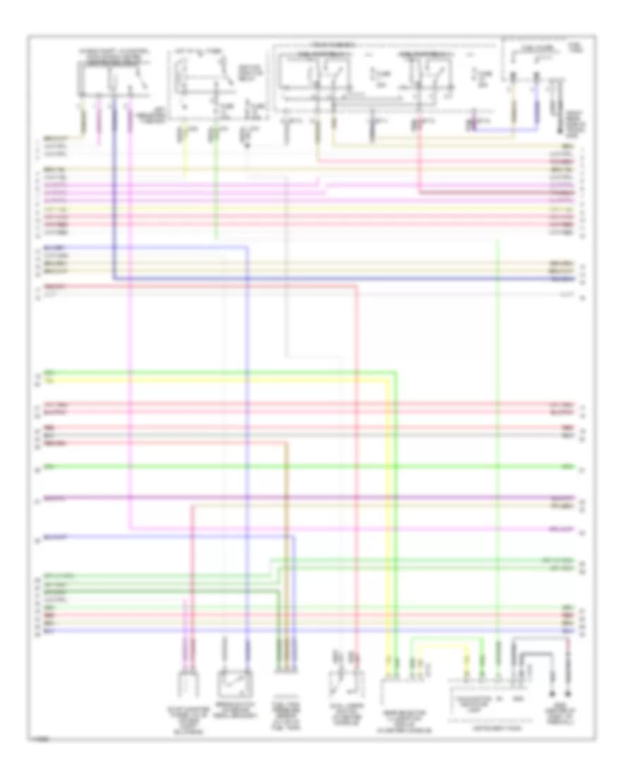
4.0L, Engine Performance Wiring Diagrams (2 of 4) for Jaguar XJR 1999
 https://portal-diagnostov.com/license.html
Automotive Electricians Portal FZCO
Automotive Electricians Portal FZCO
https://portal-diagnostov.com/license.html
https://portal-diagnostov.com/license.html
Automotive Electricians Portal FZCO
Automotive Electricians Portal FZCOList of elements for 4.0L, Engine Performance Wiring Diagrams (2 of 4) for Jaguar XJR 1999:
- (in eng compt, in control module enclosure) ignition coil relay
- Brake switch (on brake pedal bracket)
- Cc14
- Cf24
- Dual linear switch (in center console)
- Evap canister purge valve (on eng compt bulkhead)
- Fuel pump relay 1
- Fuel pump relay 4
- Fuel pumps
- Fuel tank
- Fuel tank pressure sensor (in top of fuel tank)
- Fuse 10a
- Fuse 20a
- G206 (center of dash, on firewall)
- Gear selector illumination module (in center console)
- Gnd
- Hot at all times
- Ignition positive relay
- Instrument pack
- Left heelboard fuse box
- Malfunction indicator lamp
- Pnk/
- Red
- Side of trunk) g405
- Trunk fuse box
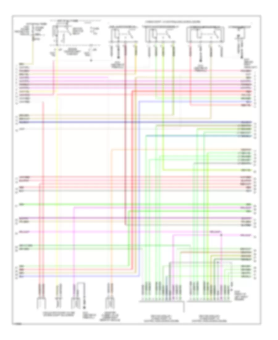
4.0L, Engine Performance Wiring Diagrams (3 of 4) for Jaguar XJR 1999
 https://portal-diagnostov.com/license.html
Automotive Electricians Portal FZCO
Automotive Electricians Portal FZCO
https://portal-diagnostov.com/license.html
https://portal-diagnostov.com/license.html
Automotive Electricians Portal FZCO
Automotive Electricians Portal FZCOList of elements for 4.0L, Engine Performance Wiring Diagrams (3 of 4) for Jaguar XJR 1999:
- (in eng compt, in control module enclosure)
- 250a
- Canister closed valve (under right rear of vehicle)
- Engine compartment fuse box
- Fuel injection relay
- Fuse 10a
- G100 (front of left front fender)
- G107 (behind right headlight)
- G121 (center of firewall)
- High power protection module
- Hot at all times
- Ignition module 1 (in eng compt, in control module enclosure)
- Ignition module 2 (in eng compt, in control module enclosure)
- Ignition positive relay
- Intercooler pump
- Intercooler pump relay
- Ls6
- Ls7
- Power fuse
- Red
- Throttle motor power relay
- Vacuum switching valves (on eng compt bulkhead)
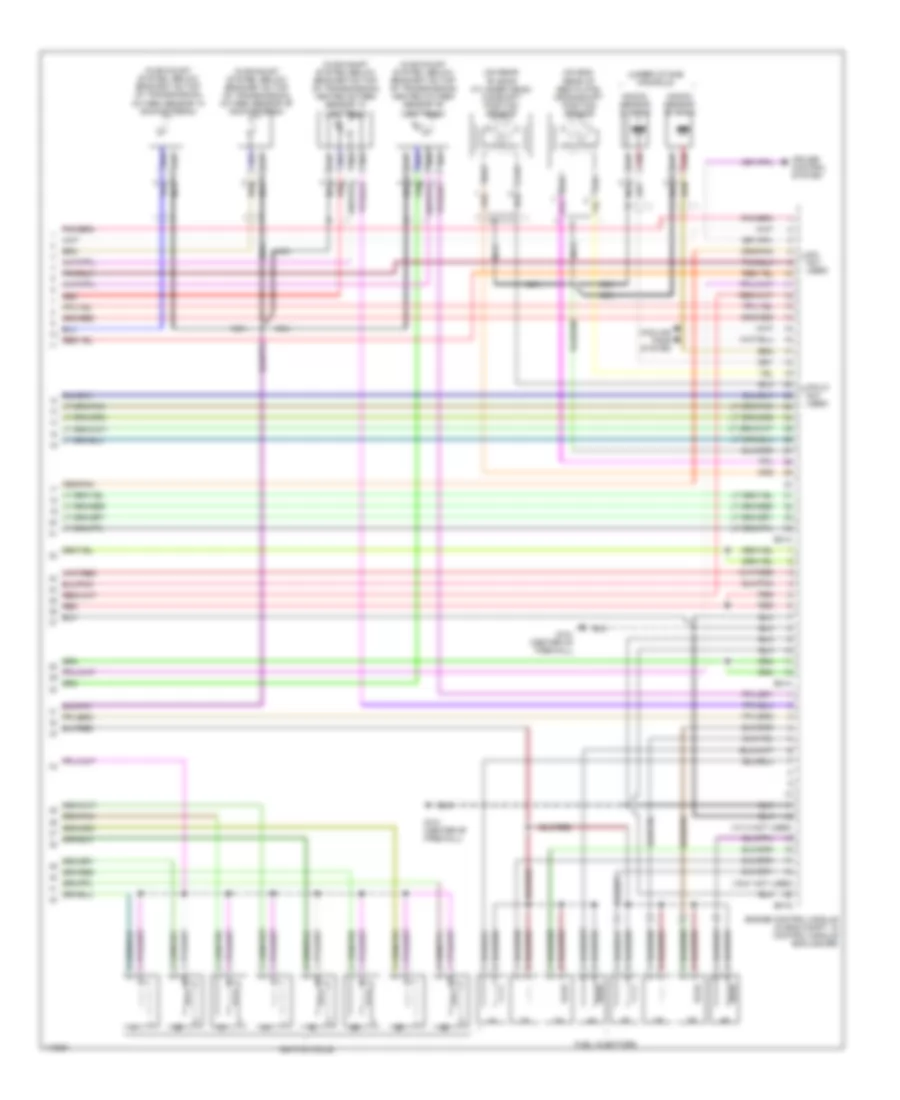
4.0L, Engine Performance Wiring Diagrams (4 of 4) for Jaguar XJR 1999
 https://portal-diagnostov.com/license.html
Automotive Electricians Portal FZCO
Automotive Electricians Portal FZCO
https://portal-diagnostov.com/license.html
https://portal-diagnostov.com/license.html
Automotive Electricians Portal FZCO
Automotive Electricians Portal FZCOList of elements for 4.0L, Engine Performance Wiring Diagrams (4 of 4) for Jaguar XJR 1999:
- (13-14 not used)
- (19-21 not used)
- (5-8 not used)
- (in exhaust system, below bracket on top of transmission) heated oxygen sensor "a" (upstream)
- (in exhaust system, below bracket on top of transmission) heated oxygen sensor "b" (upstream)
- (in exhaust system, below bracket on top of transmission) oxygen sensor "a" (downstream)
- (in exhaust system, below bracket on top of transmission) oxygen sensor "b" (downstream)
- (on eng, rear of bed plate) crankshaft position sensor
- (on rear "b" bank cylinder head) camshaft position sensor
- (pin 21 not used)
- (under intake manifold)
- Cooling fans system
- Cruise control system
- Em13
- Em14
- Em15
- Engine control module (in eng compt, in control module enclosure)
- Fuel injectors
- G121 (center of firewall)
- Ignition coils
- Knock sensor "a" bank
- Knock sensor "b" bank
- Nca
- Red

 Čeština
 Dansk
Dansk Deutsch
 Ελληνικά
 English
 English
 Español
 Suomi
Suomi Français
 Français
 עברית
עברית Hrvatski
 Magyar
 Italiano
 日本語
日本語 Nederlands
 Polski
 Português
 Português
 Română
 Русский
 Slovenčina
 Slovenščina
 Svenska
 Türkçe
 中文 (中国)
