POWER DISTRIBUTION
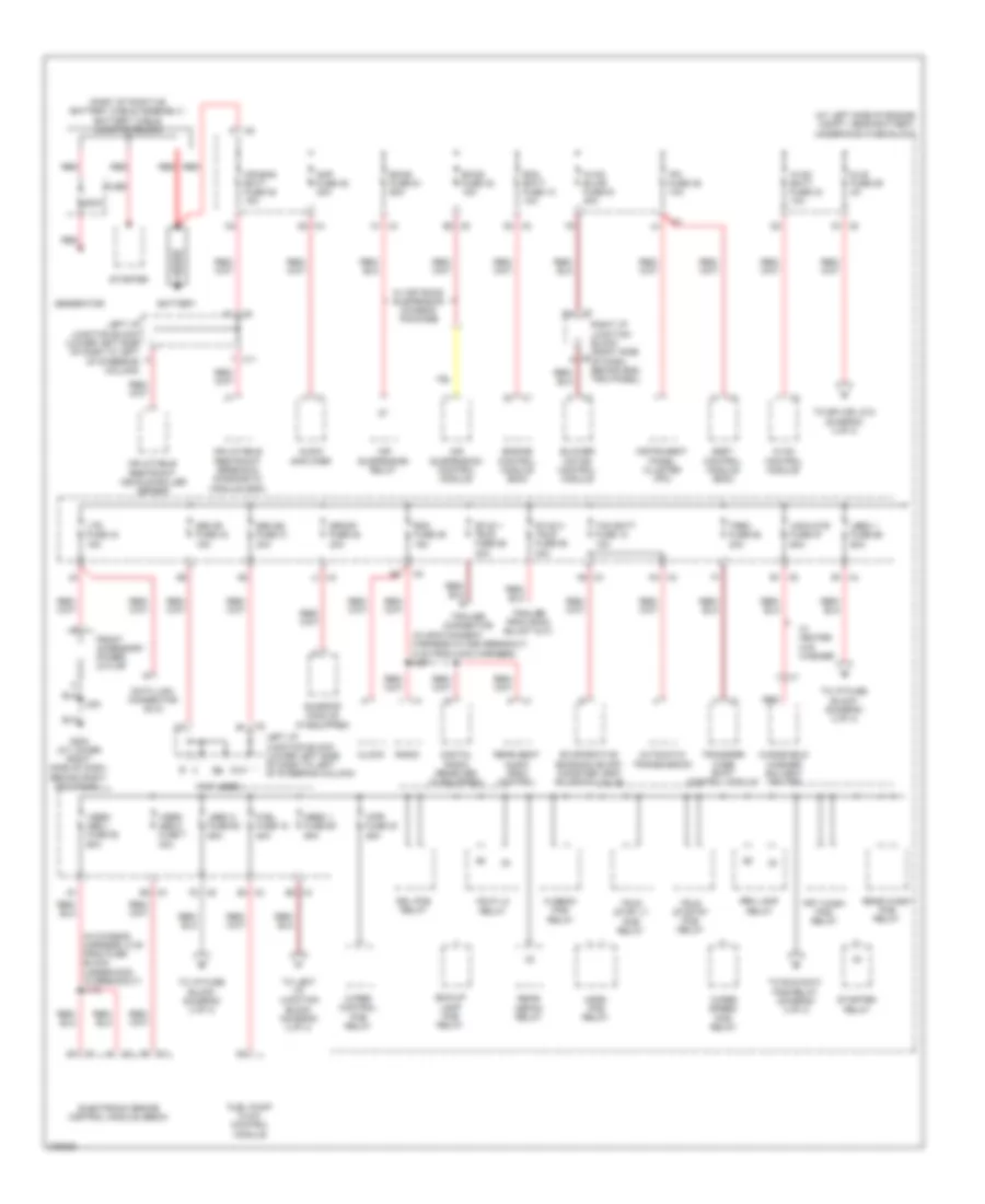
Power Distribution Wiring Diagram (1 of 4) for Hummer H2 2008
 https://portal-diagnostov.com/license.html
Automotive Electricians Portal FZCO
Automotive Electricians Portal FZCO
https://portal-diagnostov.com/license.html
https://portal-diagnostov.com/license.html
Automotive Electricians Portal FZCO
Automotive Electricians Portal FZCO
List of elements for Power Distribution Wiring Diagram (1 of 4) for Hummer H2 2008:
- (at left side of engine compt, near battery) underhood fuse block
- (in chassis harness, 8 cm from fuse block underhood x3 breakout) j110
- (in infotainment harness in x350 breakout, 6 cm from main harness) j201
- (not used)
- (part of positive battery cable assembly) battery cable junction block
- 200a
- A5 x3
- Air bag batt fuse 38 15a
- Air suspension control module
- Air suspension relay
- Amp fuse 35 30a
- Audio amplifier
- Automatic transmission
- Battery
- Bck/up lamp pcb relay
- Blower motor control module
- Body control module (bcm)
- C1 x3
- Clock
- D2 x2
- Data link connector (dlc)
- Digital radio receiver (if equipped)
- Dlis fuse 29 2a
- Drl pcb relay
- E1 x5
- E2 x4
- Ecas fuse 32 15a
- Ecas fuse 51 60a
- Ecm batt fuse 10 10a
- Electronic brake control module (ebcm)
- Engine control module (ecm)
- Evaporative emission (evap) canister vent solenoid valve
- Front accessory power outlet
- Frt wash pcb relay
- Fuel fuse 18 20a
- Fuel pump flow control module
- Fuse
- G203 (at lower right side of dash, behind right kick panel)
- G3 x4
- Generator
- Hdlp lo relay
- Hi beam pcb relay
- Horn pcb relay
- Hvac batt fuse 33 10a
- Hvac blwr fuse 61 40a
- Hvac control module
- Inflatable restraint sensing & diagnostic module (sdm)
- Inflatable restraint vehicle roller sensor
- Instrument panel cluster (ipc)
- Ipc fuse 39 10a
- J351
- Lbec 1 fuse 56 60a
- Lbec 2 fuse 62 60a
- Left i/p junction block (lower left side of dash to left of steering column)
- Ltr fuse 44 15a
- Mbec 1 fuse 60 60a
- N3 x2
- Prk lamp relay
- Radio
- Rdo fuse 36 15a
- Rear defog relay
- Rear seat audio (rsa) control
- Rear wash pcb relay
- Red
- Right i/p junction block (right side of dash, behind end trim panel)
- S/roof fuse 28 30a
- Seo b1 fuse 43 15a
- Seo b2 fuse 31 30a
- Starter
- Starter relay
- Stud 1 trlr fuse 59 40a
- Stud 2 trlr fuse 55 30a
- Sunroof module (if equipped)
- Tcm batt fuse 12 15a
- To i/p fuse block (diagram 2 of 4)
- To left i/p junction block (diagram 2 of 4)
- To run/accy pcb relay (diagram 3 of 4)
- To splice j212 (diagram 4 of 4)
- Trailer connector
- Transfer case shift control module
- Trec fuse 58 30a
- Trlr stop lt pcb relay
- Trlr stop rt pcb relay
- Vses/ abs 1 fuse 52 60a
- Vses/ abs 2 fuse 7 30a
- W/ heated w/s washer
- W/ off road suspension chassis package
- Windshield washer solvent heater
- Wiper control pcb relay
- Wiper speed pcb relay
- Wpr fuse 30 25a
- Wsw/htr fuse 57 60a
- X11
- X2 b1
- X2 d3
- X3 b3
- X3 e4
- X4 e1
- X4 j1
- X5 b2
- X5 d1
- X5 f2
- X6 a
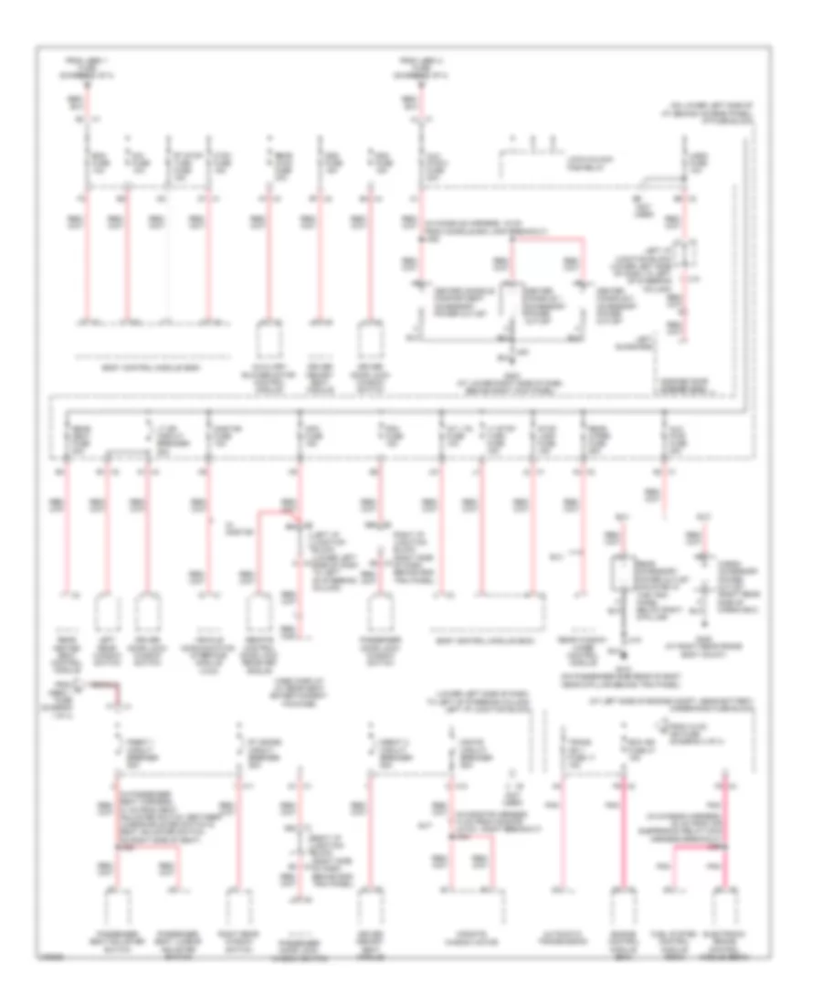
Power Distribution Wiring Diagram (2 of 4) for Hummer H2 2008
 https://portal-diagnostov.com/license.html
Automotive Electricians Portal FZCO
Automotive Electricians Portal FZCO
https://portal-diagnostov.com/license.html
https://portal-diagnostov.com/license.html
Automotive Electricians Portal FZCO
Automotive Electricians Portal FZCOList of elements for Power Distribution Wiring Diagram (2 of 4) for Hummer H2 2008:
- (at left side of engine compt, near battery) underhood fuse block
- (in chassis harness, 20 cm from air suspension relay main harness breakout) j356
- (in console harness, 16 cm from console bin lamp breakout) j352
- (lower left side of dash, to left of steering column) left i/p junction block
- (not used)
- (on lower left side of i/p, behind access panel) i/p fuse block
- A1 x4
- A7 x3
- Automatic transmission
- Aux pwr 2 fuse 20a
- Aux pwr fuse 20a
- Auxiliary blower motor control module
- B1 x2
- B4 x4
- B7 x2
- Bcm fuse 10a
- Body control module (bcm)
- Cargo accessory power outlet (right rear side of cargo box)
- Center console 1 accessory power outlet
- Center console 2 accessory power outlet
- Center console compartment accessory power outlet
- Ctsy fuse 15a
- D1 x1
- Ddm fuse 15a
- Dim fuse 10a
- Driver door lock/ window switch
- Driver memory seat module
- Dseat 2 circuit breaker 25a
- Dsm fuse 15a
- Ecm ign fuse 47 15a
- Electronic brake control module (ebcm)
- Engine control module (ecm)
- F5 x3
- From c mbec 1 fuse (diagram 1 of 4)
- From hvac ign fuse (diagram 4 of 4)
- From lbec 1 fuse (diagram 1 of 4)
- From lbec 2 fuse (diagram 1 of 4)
- Fuel system control module (fscm)
- G203 (at lower right side of dash, behind right kick panel)
- G405 (at right rear frame body mount)
- G410 (on passenger side rear of body near d-pillar behind trim panel)
- Garage door opener (gdo)
- Info fuse 15a
- Int lts fuse 10a
- J31
- J410
- Left i/p junction block (lower left side of dash to left of steering column)
- Left rear window switch
- Left sunshade
- Lock/unlock pcb relay
- Lt dr circuit breaker 25a
- Lt stop turn fuse 15a
- Mgate circuit breaker 25a
- Midgate window motor
- Onstar fuse 10a
- P5 x2
- Passenger door lock/ window switch
- Passenger seat adjuster switch
- Passenger seat lumbar adjuster switch
- Pdm fuse 15a
- Pnk
- Pseat 1 circuit breaker 25a
- Rear accessory power outlet (mounted in the trim panel below right d-pillar)
- Rear heated seat control module
- Rear hvac fuse 30a
- Rear seat fuse 20a
- Rear window wiper control module
- Rear wiper fuse 25a
- Remote control door lock receiver (rcdlr)
- Right i/p junction block (right side of dash behind end trim panel)
- Right rear window switch
- Rt doors circuit breaker 25a
- Rt stop turn fuse 15a
- Stop lamp fuse 15a
- Sut
- Suv
- Trans ign 1 fuse 17 15a
- Ugdo fuse 10a
- Vehicle communication interface module (vcim)
- Video display (w/ rear seat entertainment package)
- W/ onstar
- X1 3b2
- X1 3b4
- X1 f1
- X1 g2
- X1 j2
- X10
- X11
- X12
- X2 a4
- X2 b5
- X3 b2
- X3 b4
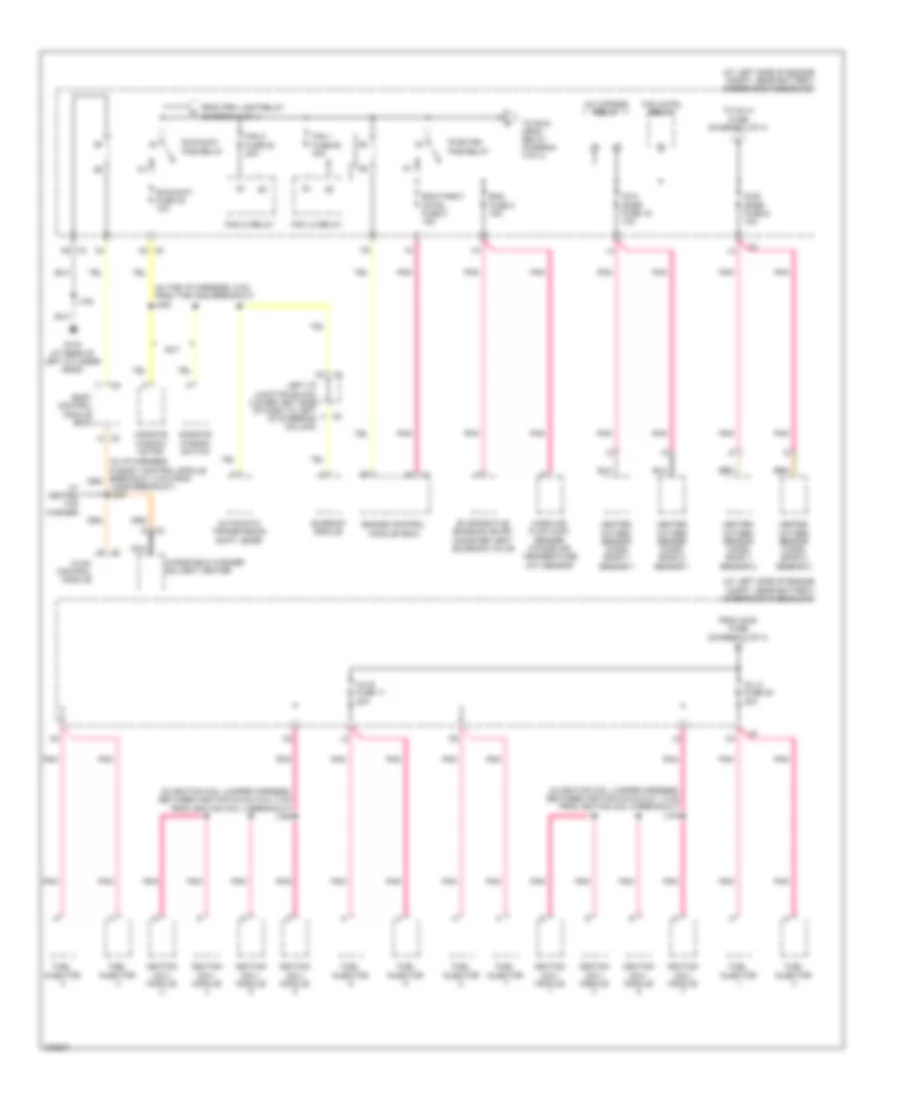
Power Distribution Wiring Diagram (3 of 4) for Hummer H2 2008
 https://portal-diagnostov.com/license.html
Automotive Electricians Portal FZCO
Automotive Electricians Portal FZCO
https://portal-diagnostov.com/license.html
https://portal-diagnostov.com/license.html
Automotive Electricians Portal FZCO
Automotive Electricians Portal FZCOList of elements for Power Distribution Wiring Diagram (3 of 4) for Hummer H2 2008:
- (at left side of engine compt, near battery) underhood fuse block
- (in i/p harness in body control module breakout, 5 cm from jx205 breakout) j230
- (in ignition coil jumper harness, between ignition coils 4 & 2, 3 cm from ignition coil 4 breakout) j160
- (in ignition coil jumper harness, between ignition coils 5 & 7, 3 cm from ignition coil 5 breakout) j140
- (in the i/p harness, 5 cm from the x205 breakout) j220
- A/c cmprsr relay
- Automatic transmission shift lever
- Body control module (bcm)
- D4 x5
- Ecm/throt cntrl fuse 3 15a
- Eng fuse 2 15a
- Engine control module (ecm)
- Evaporative emission (evap) canister vent solenoid valve
- Fan 1 fuse 50 40a
- Fan 2 fuse 53 40a
- Fan cntrl relay
- Fan hi relay
- Fan lo relay
- From o2-b fuse (diagram 3 of 4)
- From prk lamp relay (diagram 1 of 4)
- Fuel injector
- G104 (at rear of left cylinder head)
- Heated oxygen sensor (ho2s) bank 1 sensor 1
- Heated oxygen sensor (ho2s) bank 1 sensor 2
- Heated oxygen sensor (ho2s) bank 2 sensor 1
- Heated oxygen sensor (ho2s) bank 2 sensor 2
- Hvac control module
- Ignition coil/ module
- Inj a fuse 20 20a
- Inj b fuse 11 20a
- J102
- Left i/p junction block (lower left side of dash to left of steering column)
- Mass air flow (maf) sensor/ intake air temperature (iat) sensor
- Midgate window motor
- Midgate window switch
- Nca
- O2-a snsr fuse 16 10a
- O2-b snsr fuse 6 10a
- Pnk
- Pwr/trn pcb relay
- Run/accy fuse 40 10a
- Run/accy pcb relay
- Sunroof module
- Sut
- To inj-a fuse (diagram 3 of 4)
- To run/ crnk relay (diagram 4 of 4)
- W/ heated w/s washer
- Windshield washer solvent heater
- X2 n5
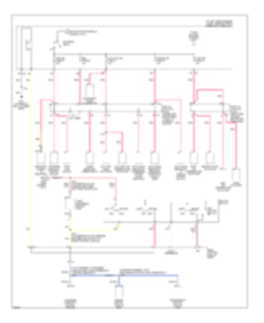
Power Distribution Wiring Diagram (4 of 4) for Hummer H2 2008
 https://portal-diagnostov.com/license.html
Automotive Electricians Portal FZCO
Automotive Electricians Portal FZCO
https://portal-diagnostov.com/license.html
https://portal-diagnostov.com/license.html
Automotive Electricians Portal FZCO
Automotive Electricians Portal FZCOList of elements for Power Distribution Wiring Diagram (4 of 4) for Hummer H2 2008:
- & body control module)
- (at left side of engine compt, near battery) underhood fuse block
- (in engine harness, 16 cm from engine control module breakout) j130
- (in i/p harness, in transfer case control module breakout, 7 cm from breakout) j234
- (not used)
- 5-volt reference
- Acc
- Air bag ign fuse 34 10a
- Aux hvac ign fuse 41 10a
- Auxiliary air temperature actuator
- Auxiliary mode actuator
- Body control module (bcm)
- Engine control module (ecm)
- From h dlis fuse diagram 1 of 4)
- From pwr/trn pcb relay (diagram 3 of 4)
- G104 (at rear of left cylinder head)
- Hvac ign fuse 46 10a
- Ign
- Ignition switch
- Inflatable restraint i/p module disable switch
- Inflatable restraint passenger air bag on/off indicator
- Inflatable restraint sensing & diagnostic module (sdm)
- Inside rearview mirror (isrvm)
- Instrument panel cluster (ipc)
- J102
- J441
- Key ignition switch
- Left air temperature actuator
- Left i/p junction block (lower left side of dash to left of steering column)
- Misc ign fuse 37 10a
- Mode actuator
- N5 x2
- Nca
- Off
- Pnk
- Rearview camera (if equipped)
- Recirculation actuator
- Right air temperature actuator
- Right i/p junction block (right side of dash behind end trim panel)
- Run
- Run/crnk relay
- Seo fuse 45 10a
- Start
- Stop lamp switch
- Theft deterrent module (tdm)
- To ecm ign fuse (diagram 2 of 4)
- Transfer case shift control module
- Transmission control module (tcm)
- X11
- X12

 Čeština
 Dansk
Dansk Deutsch
 Ελληνικά
 English
 English
 Español
 Suomi
Suomi Français
 Français
 עברית
עברית Hrvatski
 Magyar
 Italiano
 日本語
日本語 Nederlands
 Polski
 Português
 Português
 Română
 Русский
 Slovenčina
 Slovenščina
 Svenska
 Türkçe
 中文 (中国)
