POWER DISTRIBUTION
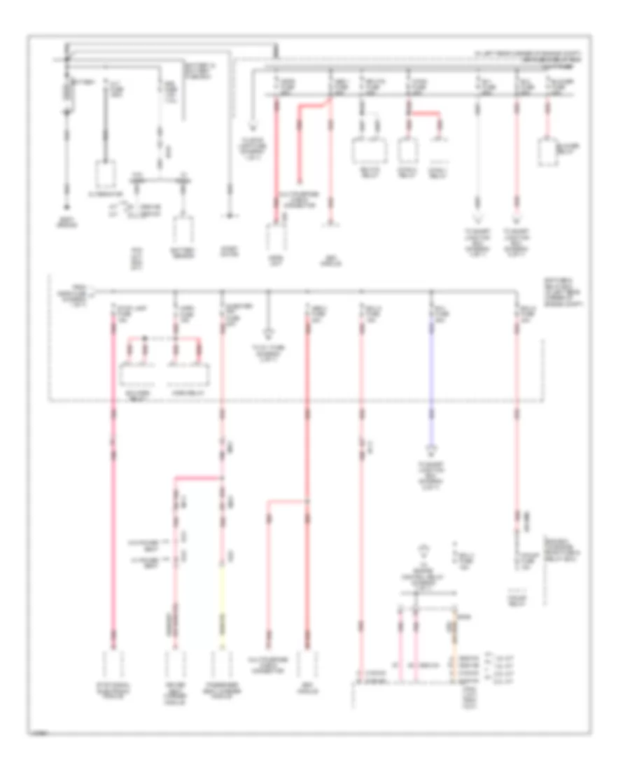
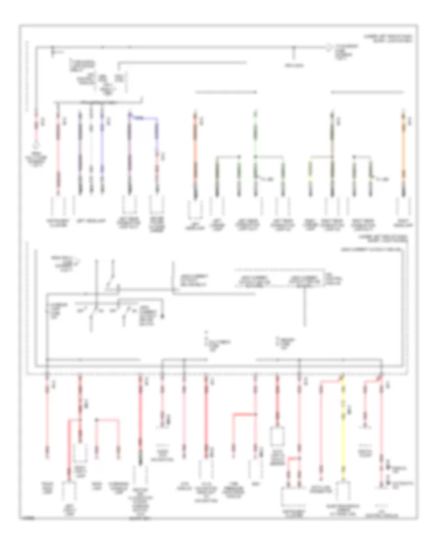
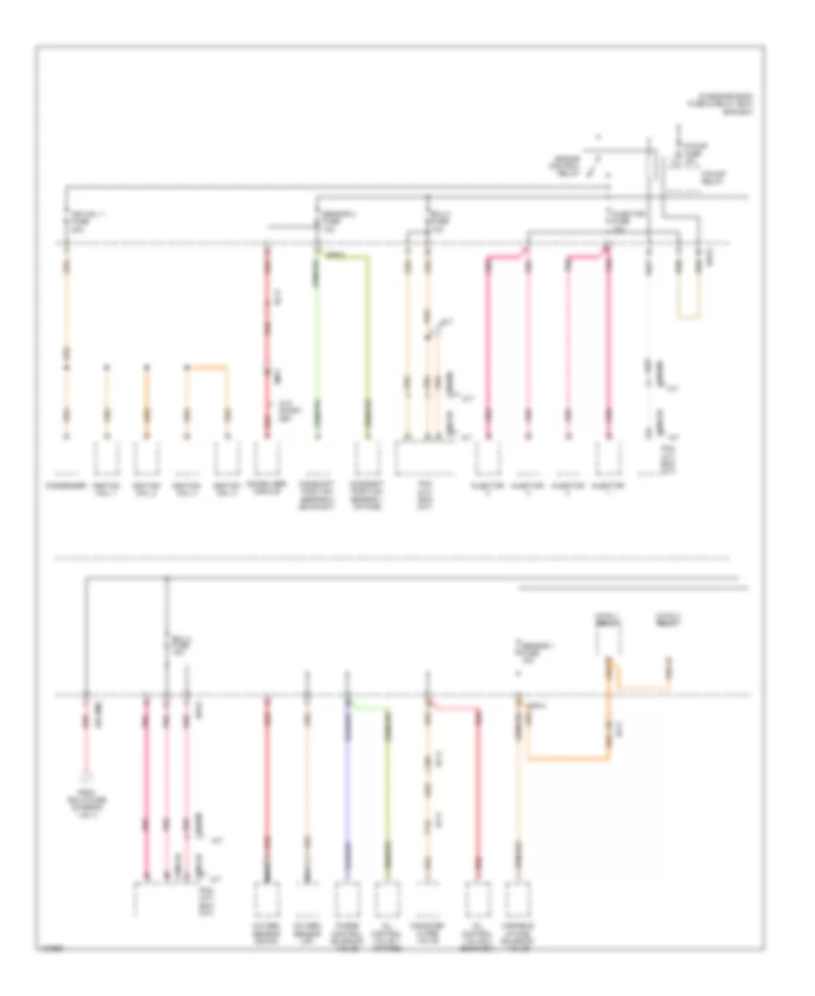
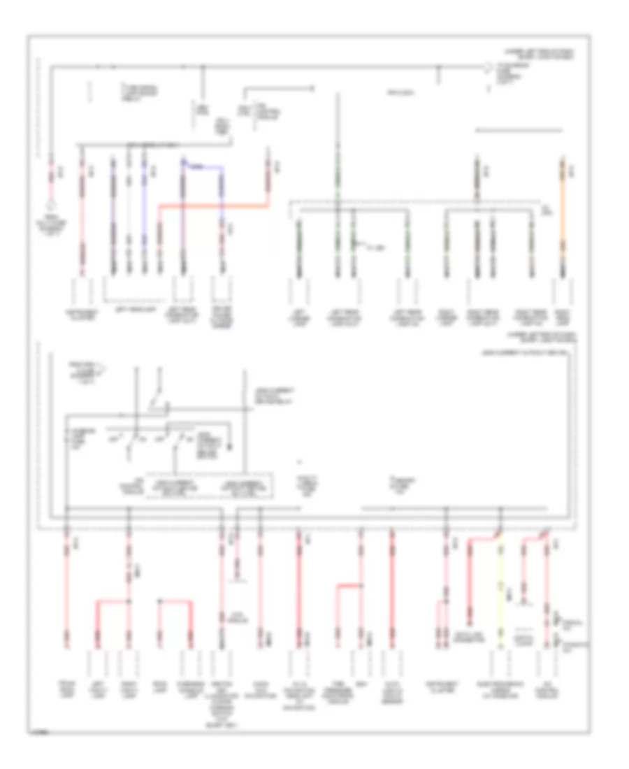
Power Distribution Wiring Diagram, MD (1 of 7) for Hyundai Elantra Limited 2014
 https://portal-diagnostov.com/license.html
Automotive Electricians Portal FZCO
Automotive Electricians Portal FZCO
https://portal-diagnostov.com/license.html
https://portal-diagnostov.com/license.html
Automotive Electricians Portal FZCO
Automotive Electricians Portal FZCO
List of elements for Power Distribution Wiring Diagram, MD (1 of 7) for Hyundai Elantra Limited 2014:
- (in left rear corner of engine compt) e/r fuse & relay box
- 1.8l a/t
- 1.8l m/t
- 2.0l a/t
- 2.0l m/t
- A/t
- Abs 1 fuse 40a
- Abs 2 fuse 30a
- Alt fuse 150a
- Alternator
- Ams fuse 7.5a (1.8l)
- B+1 fuse 60a
- B+2 fuse 60a
- B+3 fuse 50a
- B/a horn relay
- Battery
- Battery & battery fuse box
- Battery sensor
- Blower fuse 40a
- Blower relay
- Body ground
- C/fan 1 relay
- C/fan 2 relay
- C/fan fuse 40a
- C100-ak
- C100-mk
- C600-aa
- C600-ab
- C600-mk
- Driver seat warmer module
- E/r fuse & relay box (in left rear corner of engine compt)
- E/r-b
- E/r-ems
- E29
- Ec01
- Ec11
- Ecu 4 fuse 15a
- Ecu 5 fuse 15a
- Ecu 6 fuse 40a
- Em11
- Ems box (in engine room fuse & relay box)
- Esc module
- F/pump fuse 15a
- F/pump relay
- From mdps fuse a (diagram 1 of 7)
- Fs11
- Fs12
- Fs21
- Horn fuse 15a
- Horn relay
- M/t
- Mdps fuse 80a
- Mdps unit
- Mf11
- Mf61
- Multi fuse
- Multipurpose check connector
- Passenger seat warmer module
- Pcm (a/t) ecm (m/t)
- Pnk
- Red
- Rr htd fuse 40a
- Rr htd relay
- S/heater frt fuse 20a
- Start motor
- Stop lamp fuse 15a
- Stop signal electronic module
- To engine control relay (diagram 7 of 7)
- To ig 1 fuse (diagram 2 of 7)
- To smart junction box (diagram 4 of 7)
- To smart junction box (diagram 5 of 7)
- To smart junction box (diagram 6 of 7)
- To stop lamp fuse (diagram 1 of 7)
- W/ micom
- W/ power seat
- W/o micom
- W/o power seat
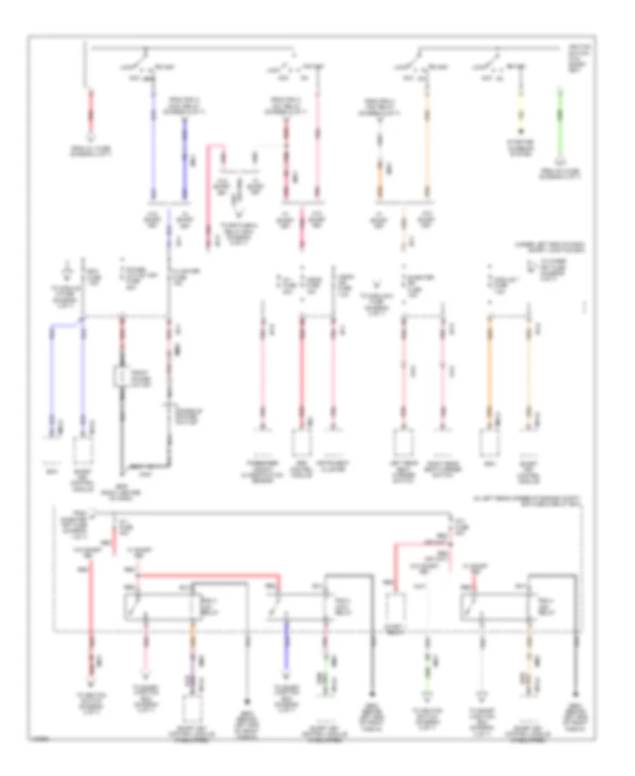
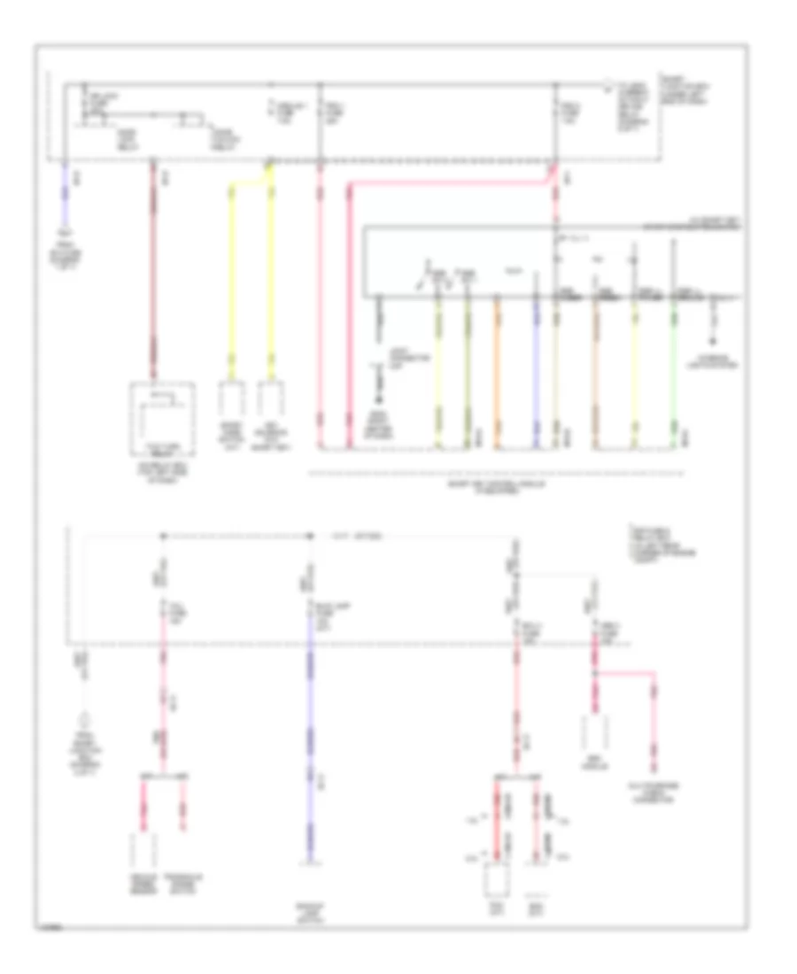
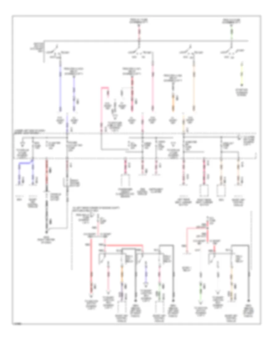
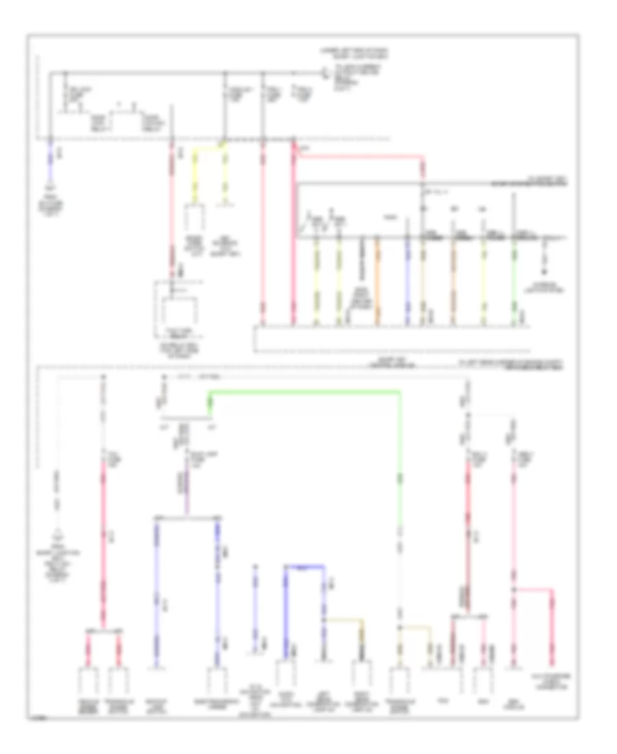
Power Distribution Wiring Diagram, MD (2 of 7) for Hyundai Elantra Limited 2014
 https://portal-diagnostov.com/license.html
Automotive Electricians Portal FZCO
Automotive Electricians Portal FZCO
https://portal-diagnostov.com/license.html
https://portal-diagnostov.com/license.html
Automotive Electricians Portal FZCO
Automotive Electricians Portal FZCOList of elements for Power Distribution Wiring Diagram, MD (2 of 7) for Hyundai Elantra Limited 2014:
- (in left rear corner of engine compt) e/r fuse & relay box
- (or pnk)
- (under left end of dash) smart junction box
- A/bag fuse 15a
- A/bag ind fuse 7.5a
- Acc
- Bcm
- Bcm fuse 7.5a
- C/lighter fuse 15a
- Console power outlet
- Em11
- Em61
- Fd31
- Fd41
- From ig 1 fuse (diagram 2 of 7)
- From ig 2 fuse (diagram 2 of 7)
- From p s/heater frt fuse (diagram 1 of 7)
- From pdm 2 (acc) relay (diagram 2 of 7)
- From pdm 3 (ig1) relay (diagram 2 of 7)
- From pdm 4 (ig2) relay (diagram 2 of 7)
- Front power outlet
- Ge02 (behind left end of front fascia)
- Gm02 (right center of dash)
- I/p-b
- I/p-e
- I/p-f
- I/p-h
- Ig 1 fuse 20a
- Ig 1 fuse 40a
- Ig 2 fuse 40a
- Ignition switch (w/o smart key)
- Instrument cluster
- Left rear seat warmer switch
- Lock
- M02-a
- M13-a
- M52
- Mm01
- Module 7 fuse 7.5a
- Nca
- Passenger weight classification sensor
- Pdm 2 (acc) relay
- Pdm 3 (ig1) relay
- Pdm 4 (ig2) relay
- Pnk
- Power outlet frt fuse 20a
- Red
- Right rear seat warmer switch
- S/heater rr fuse 15a
- Smart key control module
- Smart key control module (if equipped)
- Srs control module
- Start
- Start 1 relay
- Starting/ charging system
- To e/r fuse & relay box (diagram 6 of 7)
- To ignition switch (diagram 2 of 7)
- To module 2 fuse (diagram 3 of 7)
- To module 6 fuse (diagram 3 of 7)
- To smart junction box (diagram 2 of 7)
- To wiper frt fuse (diagram 3 of 7)
- W/ smart key
- W/o smart key
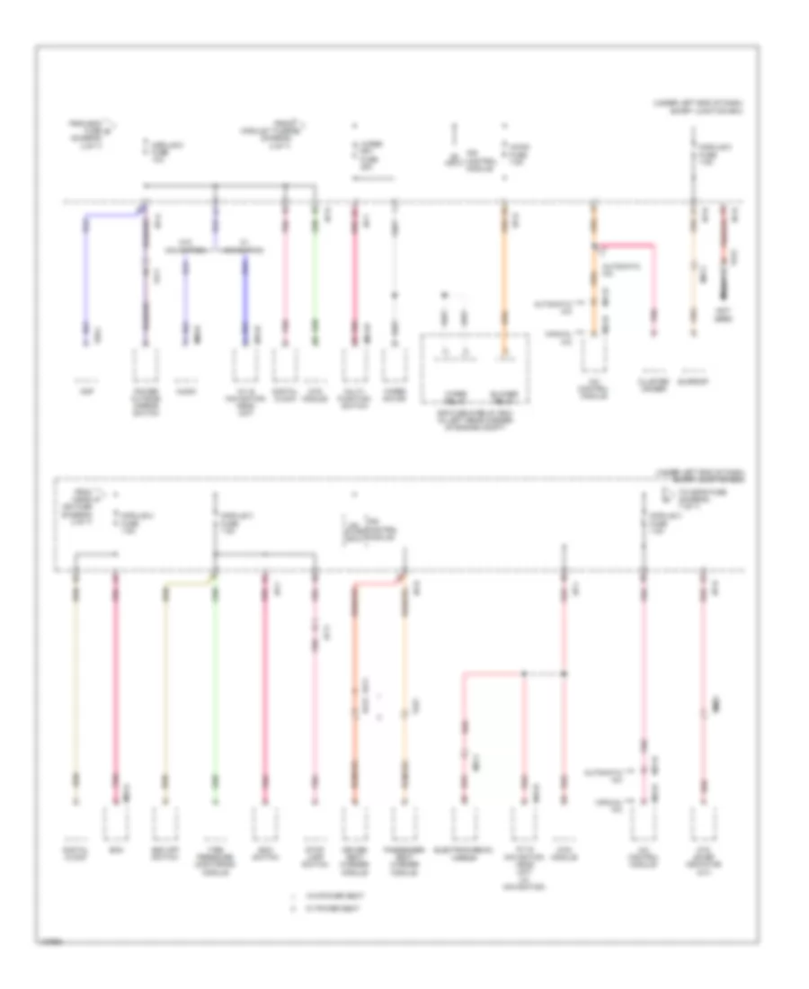
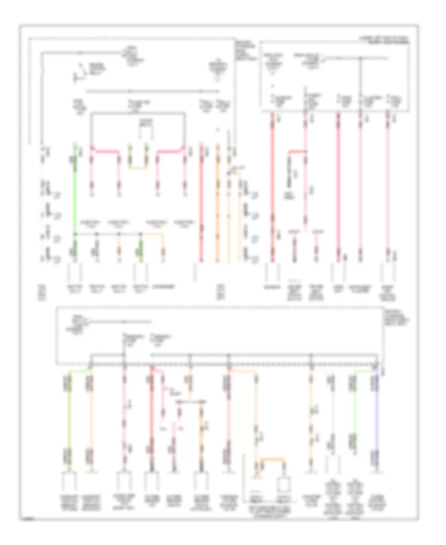
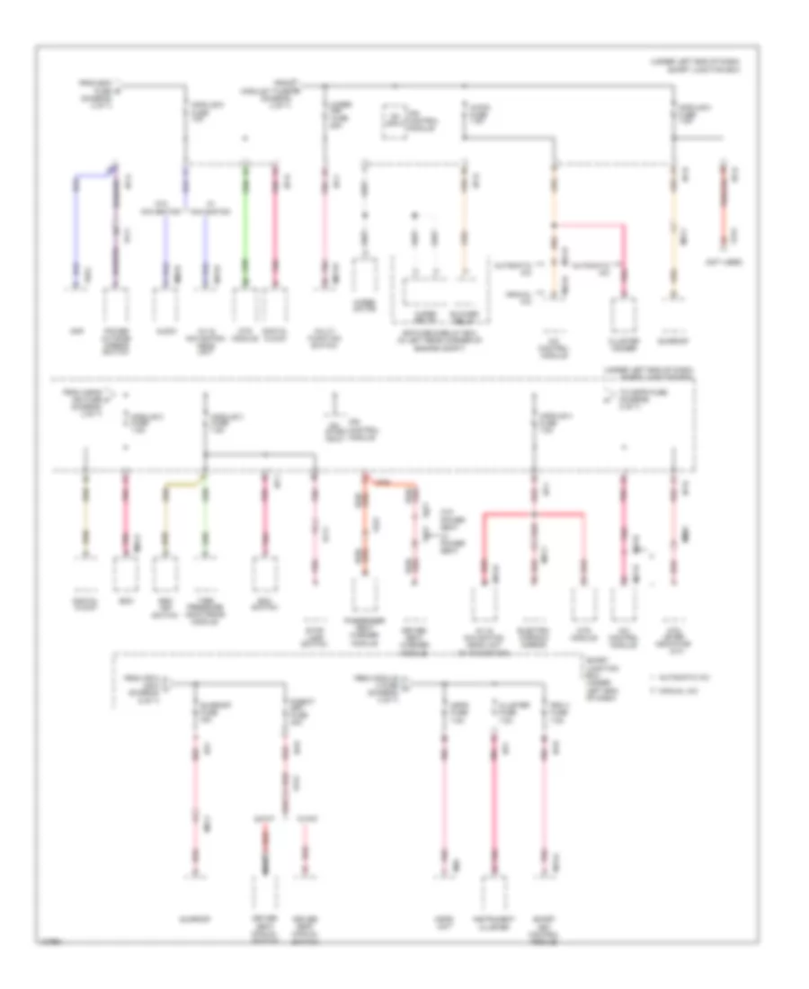
Power Distribution Wiring Diagram, MD (3 of 7) for Hyundai Elantra Limited 2014
 https://portal-diagnostov.com/license.html
Automotive Electricians Portal FZCO
Automotive Electricians Portal FZCO
https://portal-diagnostov.com/license.html
https://portal-diagnostov.com/license.html
Automotive Electricians Portal FZCO
Automotive Electricians Portal FZCOList of elements for Power Distribution Wiring Diagram, MD (3 of 7) for Hyundai Elantra Limited 2014:
- (not used)
- (under left end of dash) smart junction box
- A/c control module
- A/con fuse 7.5a
- A/v & navigation head unit
- A/v & navigation head unit (w/ navigation)
- Amp
- Atm lever indicator (a/t)
- Audio
- Automatic a/c
- Bcm
- Blower relay
- Cluster ionizer
- Digital clock
- Driver seat warmer module
- E/r fuse & relay box (in left rear corner of engine compt)
- Eco switch
- Ef11
- Electrochromic mirror
- Esc off switch
- F02-c
- Fd11
- From a/bag f ind fuse (diagram 2 of 7)
- From bcm fuse e (diagram 2 of 7)
- From module 7 fuse g (diagram 2 of 7)
- Fs11
- Fs12
- Fs21
- I/p-a
- I/p-b
- I/p-e
- I/p-f
- I/p-h
- Input
- Ips control module
- M01-w
- M02-a
- M09-b
- M15-b
- M21-b
- M22-b
- Manual a/c
- Mm01
- Module 2 fuse 7.5a
- Module 3 fuse 7.5a
- Module 4 fuse 7.5a
- Module 5 fuse 7.5a
- Module 6 fuse 10a
- Mr11
- Mts module
- Multi- function switch
- Nca
- On/ start input
- Passenger seat warmer module
- Pnk
- Power outside mirror switch
- Red
- Stop lamp switch
- Sunroof
- Tire pressure monitoring module
- To mdps fuse (diagram 7 of 7)
- W/ navigation
- W/ power seat
- W/o navigation
- W/o power seat
- Wiper frt fuse 25a
- Wiper motor
- Wiper relay
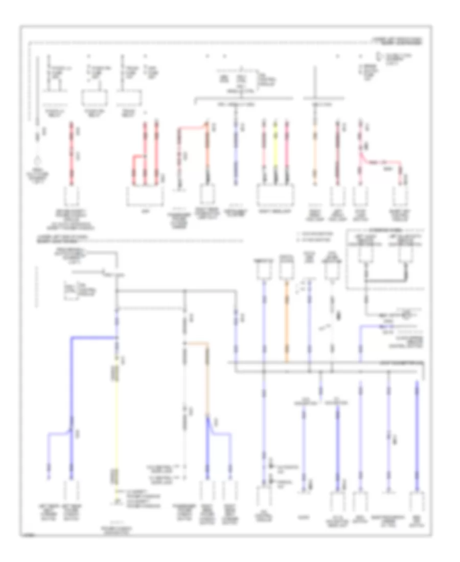
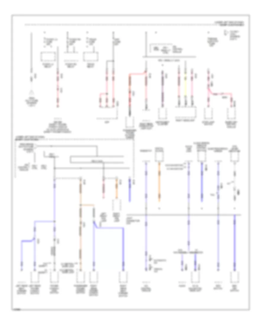
Power Distribution Wiring Diagram, MD (4 of 7) for Hyundai Elantra Limited 2014
 https://portal-diagnostov.com/license.html
Automotive Electricians Portal FZCO
Automotive Electricians Portal FZCO
https://portal-diagnostov.com/license.html
https://portal-diagnostov.com/license.html
Automotive Electricians Portal FZCO
Automotive Electricians Portal FZCOList of elements for Power Distribution Wiring Diagram, MD (4 of 7) for Hyundai Elantra Limited 2014:
- (under left end of dash) smart junction box
- A/c control module
- A/t
- A/v & navigation head unit
- Amp
- Amp fuse 25a
- Atm lever indicator
- Audio
- Automatic a/c
- Aux & usb jack
- Brake switch fuse 10a
- Clock spring (remote control switch)
- Digital clock
- Driver safety power window module (w/ auto up/down & safety power window)
- Eco switch
- Electrochromic mirror (w/ tmu)
- Em11
- Em61
- Esc off switch
- F02-c
- Fd11
- Fd21
- Fd31
- Fd41
- From brake switch fuse j (diagram 4 of 7)
- From multi fuse (diagram 1 of 7)
- I/p-b
- I/p-d
- I/p-e
- I/p-f
- I/p-g
- I/p-h
- Instrument cluster
- Ips 1 arisu-lt (4ch)
- Ips 1 arisu-lt ctrl
- Ips 3 (1ch)
- Ips 3 ctrl
- Ips 7 (1ch)
- Ips 7 ctrl
- Ips control module
- Joint connector umc
- Left audio remote control switch
- Left front fog lamp
- Left rear power window switch
- Left rear seat warmer switch
- M01-r
- M09-a
- M13-b
- M15-a
- M21-a
- M22-b
- Manual a/c
- Mem pwr
- Mm01
- Mm02
- Mr11
- Nca
- P/wdw lh fuse 25a
- P/wdw lh relay
- P/wdw rh fuse 25a
- P/wdw rh relay
- Passenger power outside mirror
- Passenger power window switch
- Pnk
- Power window main switch
- Red
- Rheostat
- Right front fog lamp
- Right headlamp
- Right rear combination lamp (out)
- Right rear power window switch
- Right rear seat warmer switch
- Smart key control module
- Steering wheel
- Stop lamp switch
- To ips 7 (1ch) (diagram 4 of 7)
- Trunk fuse 10a
- Trunk relay
- W/ central door lock
- W/ navigation
- W/ safety power windows
- W/o central door lock
- W/o navigation
- W/o safety power windows
Power Distribution Wiring Diagram, MD (5 of 7) for Hyundai Elantra Limited 2014
 https://portal-diagnostov.com/license.html
Automotive Electricians Portal FZCO
Automotive Electricians Portal FZCO
https://portal-diagnostov.com/license.html
https://portal-diagnostov.com/license.html
Automotive Electricians Portal FZCO
Automotive Electricians Portal FZCOList of elements for Power Distribution Wiring Diagram, MD (5 of 7) for Hyundai Elantra Limited 2014:
- (under left end of dash) smart junction box
- A/c control module
- A/v & navigation head unit (w/ navigation)
- Audio (w/o navigation)
- Auto light & photo sensor
- Automatic a/c
- Bcm
- Data link connector
- Digital clock
- Driver power outside mirror
- Electrochromic mirror (w/ home link)
- Fd11
- From multi fuse (diagram 1 of 7)
- From pdm 2 fuse n (diagram 6 of 7)
- I/p-a
- I/p-b
- I/p-d
- I/p-e
- I/p-f
- I/p-g
- I/p-h
- Ignition key illumination & door warning switch (w/o smart key)
- Instrument cluster
- Interior lamp fuse 10a
- Ips 4 arisu-lt (4ch)
- Ips 4 arisu-lt ctrl
- Ips 8 (2ch)
- Ips 8 ctrl
- Ips control module
- Leak current autocut device
- Leak current autocut device relay
- Leak current autocut device rly ctrl
- Leak current autocut device sw ctrl
- Leak current autocut device switch
- Left headlamp
- Left license lamp
- Left rear combination lamp (in)
- Left rear combination lamp (out)
- Left vanity lamp
- M02-a
- M09-b
- M15-b
- M21-b
- M22-b
- Manual a/c
- Mem pwr
- Memory fuse 10a
- Mr11
- Mts module
- Multimedia fuse 15a
- Nca
- Off
- Overhead console lamp
- Pnk
- Red
- Right headlamp
- Right license lamp
- Right rear combination lamp (in)
- Right rear combination lamp (out)
- Right vanity lamp
- Room lamp
- Tire pressure monitoring module
- To sunroof fuse (diagram 7 of 7)
- Trunk room lamp
- Turn signal lamp sound relay
- W/ led
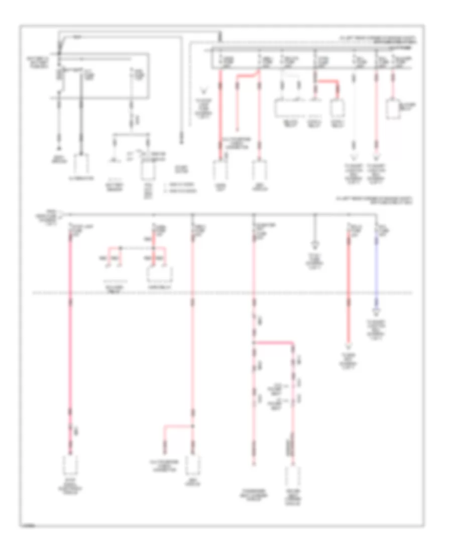
Power Distribution Wiring Diagram, MD (6 of 7) for Hyundai Elantra Limited 2014
 https://portal-diagnostov.com/license.html
Automotive Electricians Portal FZCO
Automotive Electricians Portal FZCO
https://portal-diagnostov.com/license.html
https://portal-diagnostov.com/license.html
Automotive Electricians Portal FZCO
Automotive Electricians Portal FZCOList of elements for Power Distribution Wiring Diagram, MD (6 of 7) for Hyundai Elantra Limited 2014:
- (ill +)
- (ill -)
- (or red)
- (or red) pnk
- (w/ smart key) start stop button switch
- 1.8l
- 2.0l
- A/t
- Abs 3 fuse 10a
- B/up lamp fuse 10a (m/t)
- Backup lamp switch
- C100-ak
- C100-mk
- C600-ab
- C600-mk
- Door lock relay
- Door unlock relay
- Dr lock fuse 20a
- E/r fuse & relay box (in left rear corner of engine compt)
- Ec11
- Ecm (m/t)
- Ecu 3 fuse 10a
- Esc module
- From b+3 fuse (diagram 1 of 7)
- From smart junction box (diagram 2 of 7)
- Gm02 (right center of dash)
- I/p-d
- I/p-f
- I/p-h
- Icm relay box (top left side of dash)
- Interior lights system
- Joint connector umf
- Key solenoid (w/o smart key)
- M/t
- M13-a
- M13-b
- M13-c
- Module 1 fuse 7.5a
- Multipurpose check connector
- Pcm (a/t)
- Pdm 1 fuse 25a
- Pdm 2 fuse 7.5a
- Pnk
- Red
- Smart junction box (under left end of dash)
- Smart key control module (if equipped)
- Sport mode switch (a/t)
- Ssb amber
- Ssb green
- Ssb ill ground
- Ssb ill power
- Ssb sw 1
- Ssb sw 2
- Tcu fuse 15a
- To leak current autocut device relay (diagram 5 of 7)
- Transaxle range switch
- Two turn relay
- Vehicle speed sensor
Power Distribution Wiring Diagram, MD (7 of 7) for Hyundai Elantra Limited 2014
 https://portal-diagnostov.com/license.html
Automotive Electricians Portal FZCO
Automotive Electricians Portal FZCO
https://portal-diagnostov.com/license.html
https://portal-diagnostov.com/license.html
Automotive Electricians Portal FZCO
Automotive Electricians Portal FZCOList of elements for Power Distribution Wiring Diagram, MD (7 of 7) for Hyundai Elantra Limited 2014:
- (not used)
- (or pnk) red
- (under left end of dash) smart junction box
- 1.8l
- 1.8l a/t
- 1.8l m/t
- 2-way
- 2.0l
- 2.0l a/t
- 2.0l m/t
- 8-way
- C/fan 1 relay
- C/fan 2 relay
- C100-ak
- C100-mk
- C600-ab
- C600-mk
- Camshaft position sensor 1 (intake)
- Camshaft position sensor 2 (exhaust)
- Canister close valve
- Cluster 1 fuse 7.5a
- Condenser
- Driver seat manual switch
- E/r fuse & relay box (in left rear corner of engine compt)
- E/r-a
- E/r-b
- Ec11
- Ecu 1 fuse 20a
- Ecu 2 fuse 10a
- Ef11
- Em11
- Ems box (in engine room fuse & relay box)
- Engine control relay
- F/pump relay
- Fd11
- From ecu 2 fuse (diagram 7 of 7)
- From ecu 4 fuse (diagram 1 of 7)
- From ips 8 (2ch) (diagram 5 of 7)
- From module 4 fuse h (diagram 3 of 7)
- Fs12
- I/p-b
- I/p-f
- I/p-h
- Ign coil fuse 20a
- Ignition coil 1
- Ignition coil 2
- Ignition coil 3
- Ignition coil 4
- Immobilizer module (w/o smart key)
- Injector 1 (1.8l)
- Injector 2 (1.8l)
- Injector 3 (1.8l)
- Injector 4 (1.8l)
- Injector fuse 10a
- Instrument cluster
- M13-a
- M26
- Mdps fuse 10a
- Mdps unit
- Mr11
- Nca
- Oil control valve 1 (intake) (1.8l) oil control valve 2 (exhaust) (2.0l)
- Oil control valve 1 (intake) (2.0l) oil control valve 2 (exhaust) (1.8l)
- Oxygen sensor (down)
- Oxygen sensor (down) (w/o sulev)
- Oxygen sensor (up)
- P/seat drv fuse 30a
- Pcm (a/t) ecm (m/t)
- Pdm 3 fuse 7.5a
- Pnk
- Purge control solenoid valve
- Red
- Sensor 1 fuse 10a
- Sensor 2 fuse 10a
- Smart key control module
- Sunroof
- Sunroof fuse 15a
- To sensor 2 (diagram 7 of 7)
- Variable intake solenoid valve
- W/ sulev
Power Distribution Wiring Diagram, UD (1 of 7) for Hyundai Elantra Limited 2014
 https://portal-diagnostov.com/license.html
Automotive Electricians Portal FZCO
Automotive Electricians Portal FZCO
https://portal-diagnostov.com/license.html
https://portal-diagnostov.com/license.html
Automotive Electricians Portal FZCO
Automotive Electricians Portal FZCOList of elements for Power Distribution Wiring Diagram, UD (1 of 7) for Hyundai Elantra Limited 2014:
- (in left rear corner of engine compt) e/r fuse & relay box
- A/t
- Abs 1 fuse 40a
- Abs 2 fuse 30a red
- Alt fuse 150a
- Alternator
- Ams fuse 7.5a
- Ams w/ micom
- Ams w/o micom
- B+1 fuse 60a
- B+2 fuse 60a
- B+3 fuse 50a
- B/a horn relay
- Battery
- Battery & battery fuse box
- Battery sensor
- Blower fuse 40a
- Blower relay
- Body ground
- C/fan 1 relay
- C/fan 2 relay
- C/fan fuse 40a
- C600-ab
- C600-mk
- Driver seat warmer module
- E29
- Ec01
- Ecu 6 fuse 40a
- Em11
- Esc module
- From mdps fuse (diagram 1 of 7)
- Fs11
- Fs12
- Fs21
- Horn fuse 15a
- Horn relay
- M/t
- Mdps fuse 80a
- Mdps unit
- Mf11
- Mf61
- Multi fuse
- Multipurpose check connector
- Passenger seat warmer module
- Pcm (a/t) ecm (m/t)
- Pnk
- Red
- Rr htd fuse 40a
- Rr htd relay
- S/heater frt fuse 20a
- Start motor
- Stop lamp fuse 15a pnk
- Stop signal electronic module
- To ems box (diagram 2 of 7)
- To ig 1 fuse (diagram 3 of 7)
- To smart junction box (diagram 5 of 7)
- To smart junction box (diagram 6 of 7)
- To smart junction box (diagram 7 of 7)
- To stop lamp fuse (diagram 1 of 7)
- W/ power seat
- W/o power seat
Power Distribution Wiring Diagram, UD (2 of 7) for Hyundai Elantra Limited 2014
 https://portal-diagnostov.com/license.html
Automotive Electricians Portal FZCO
Automotive Electricians Portal FZCO
https://portal-diagnostov.com/license.html
https://portal-diagnostov.com/license.html
Automotive Electricians Portal FZCO
Automotive Electricians Portal FZCOList of elements for Power Distribution Wiring Diagram, UD (2 of 7) for Hyundai Elantra Limited 2014:
- (in engine room fuse & relay box) ems box
- A/t
- C/fan 1 relay
- C/fan 2 relay
- C600-aa
- C600-ab
- C600-mk
- Camshaft position sensor 1 (intake)
- Camshaft position sensor 2 (exhaust)
- Canister close valve
- Condenser
- E/r-a
- E/r-b
- E/r-ems
- Ec11
- Ecu 2 fuse 10a
- Ecu 4 fuse 15a
- Ef11
- Em11
- Engine control relay
- F/pump fuse 15a
- F/pump relay
- From ecu 6 fuse (diagram 1 of 7)
- Ign coil 1 fuse 20a
- Ignition coil 1
- Ignition coil 2
- Ignition coil 3
- Ignition coil 4
- Immobilizer module
- Injector
- Injector fuse 10a
- M/t
- Nca
- Oil control valve 1 (intake)
- Oil control valve 2 (exhaust)
- Oxygen sensor (down)
- Oxygen sensor (up)
- Pcm (a/t) ecm (m/t)
- Pnk
- Purge control solenoid valve
- Red
- Sensor 1 fuse 10a
- Sensor 2 fuse 10a
- Variable intake solenoid valve
- W/o smart key
Power Distribution Wiring Diagram, UD (3 of 7) for Hyundai Elantra Limited 2014
 https://portal-diagnostov.com/license.html
Automotive Electricians Portal FZCO
Automotive Electricians Portal FZCO
https://portal-diagnostov.com/license.html
https://portal-diagnostov.com/license.html
Automotive Electricians Portal FZCO
Automotive Electricians Portal FZCOList of elements for Power Distribution Wiring Diagram, UD (3 of 7) for Hyundai Elantra Limited 2014:
- (in left rear corner of engine compt) e/r fuse & relay box
- (or pnk)
- (under left end of dash) smart junction box
- A/bag fuse 15a
- A/bag ind fuse 7.5a
- Acc
- Bcm
- Bcm fuse 7.5a
- C/lighter fuse 15a
- Console power outlet
- Em11
- Em61
- Fd31
- Fd41
- From ecu 6 p fuse (diagram 1 of 7)
- From ig 1 fuse (diagram 3 of 7)
- From ig 2 fuse (diagram 3 of 7)
- From pdm 2 (acc) relay (diagram 3 of 7)
- From pdm 3 (ig1) relay (diagram 3 of 7)
- From pdm 4 (ig2) relay (diagram 3 of 7)
- Front power outlet
- Ge02 (behind left end of front fascia)
- Gm02 (right center of dash)
- I/p-b
- I/p-e
- I/p-f
- I/p-h
- Ig 1 fuse 20a
- Ig 1 fuse 40a
- Ig 2 fuse 40a
- Ignition switch (w/o smart key) lock
- Instrument cluster
- Key
- Left rear seat warmer switch
- Lock
- M02-a
- M13-a
- M52
- Mm01
- Module 7 fuse 7.5a
- Nca
- Passenger weight classification sensor
- Pdm 2 (acc) relay
- Pdm 3 (ig1) relay
- Pdm 4 (ig2) relay
- Pnk
- Power outlet frt fuse 20a
- Red
- Right rear seat warmer switch
- S/heater rr fuse 15a
- Smart
- Smart key control module
- Srs control module
- Start
- Start 1 relay
- Starting/ charging system
- To e/r fuse & relay box (diagram 7 of 7)
- To ignition switch (diagram 3 of 7)
- To module 2 fuse (diagram 4 of 7)
- To module 6 fuse (diagram 4 of 7)
- To smart junction box (diagram 3 of 7)
- To wiper frt fuse (diagram 4 of 7)
- W/ smart key
- W/o
- W/o smart key
Power Distribution Wiring Diagram, UD (4 of 7) for Hyundai Elantra Limited 2014
 https://portal-diagnostov.com/license.html
Automotive Electricians Portal FZCO
Automotive Electricians Portal FZCO
https://portal-diagnostov.com/license.html
https://portal-diagnostov.com/license.html
Automotive Electricians Portal FZCO
Automotive Electricians Portal FZCOList of elements for Power Distribution Wiring Diagram, UD (4 of 7) for Hyundai Elantra Limited 2014:
- (a/t)
- (not used)
- (under left end of dash) smart junction box
- 2-way
- 8-way
- A/c control module
- A/con fuse 7.5a
- A/v & navigation head unit
- A/v & navigation head unit (w/ navigation)
- Amp
- Atm lever indicator
- Audio
- Automatic a/c
- Bcm
- Blower relay
- Cluster fuse 7.5a
- Cluster ionizer
- Digital clock
- Driver seat manual switch
- Driver seat warmer module
- E/r fuse & relay box (in left rear corner of engine compt)
- Eco switch
- Ef11
- Electro- chromic mirror
- Esc off switch
- F02-c
- Fd11
- From a/bag ind fuse f (diagram 3 of 7)
- From bcm fuse e (diagram 3 of 7)
- From ips 8 (2ch) l (diagram 6 of 7)
- From module 4 fuse h (diagram 4 of 7)
- From module 7 fuse g (diagram 3 of 7)
- Fs11
- Fs12
- Fs21
- I/p-a
- I/p-b
- I/p-e
- I/p-f
- I/p-h
- Input
- Instrument cluster
- Ips control module
- M01-w
- M02-a
- M09-b
- M13-a
- M15-b
- M21-b
- M22-b
- M26
- Manual a/c
- Mdps fuse 7.5a
- Mdps unit
- Mm01
- Module 2 fuse 7.5a
- Module 3 fuse 7.5a
- Module 4 fuse 7.5a
- Module 5 fuse 7.5a
- Module 6 fuse 10a
- Mr11
- Mts module
- Multi- function switch
- Nca
- On/ start input
- P/seat drv fuse 30a
- Passenger seat warmer module
- Pdm 3 fuse 7.5a
- Pnk
- Power outside mirror switch
- Red
- Smart junction box (under left end of dash)
- Smart key control module
- Stop lamp switch
- Sunroof
- Sunroof fuse 15a
- Tire pressure monitoring module
- To mdps fuse (diagram 4 of 7)
- W/ navigation
- W/ power seat
- W/o navigation
- W/o power seat
- Wiper frt fuse 25a
- Wiper motor
- Wiper relay
Power Distribution Wiring Diagram, UD (5 of 7) for Hyundai Elantra Limited 2014
 https://portal-diagnostov.com/license.html
Automotive Electricians Portal FZCO
Automotive Electricians Portal FZCO
https://portal-diagnostov.com/license.html
https://portal-diagnostov.com/license.html
Automotive Electricians Portal FZCO
Automotive Electricians Portal FZCOList of elements for Power Distribution Wiring Diagram, UD (5 of 7) for Hyundai Elantra Limited 2014:
- (under left end of dash) smart junction box
- A/c control module
- A/t
- A/v & navigation head unit
- Amp
- Amp fuse 25a
- Atm lever indicator
- Audio
- Automatic a/c
- Aux & usb jack
- Brake switch fuse 10a
- Clock spring (remote control switch)
- Digital clock
- Driver safety power window module (w/ auto up/down & safety power window)
- Eco switch
- Electrochromic mirror
- Em11
- Em61
- Esc off switch
- F02-c
- Fd11
- Fd21
- Fd31
- Fd41
- From brake switch fuse j (diagram 5 of 7)
- From multi fuse (diagram 1 of 7)
- I/p-b
- I/p-d
- I/p-e
- I/p-f
- I/p-g
- I/p-h
- Instrument cluster
- Ips 1 arisu-lt (4ch)
- Ips 1 arisu-lt ctrl
- Ips 3 (1ch)
- Ips 3 ctrl
- Ips 7 (1ch)
- Ips 7 ctrl
- Ips control module
- Joint connector umc
- Left front fog lamp
- Left rear power window switch
- Left rear seat warmer switch
- M01-r
- M09-a
- M13-b
- M15-a
- M21-a
- M22-b
- Manual a/c
- Mem pwr
- Mm01
- Mr11
- Nca
- P/wdw lh fuse 25a
- P/wdw lh relay
- P/wdw rh fuse 25a
- P/wdw rh relay
- Passenger power outside mirror
- Passenger power window switch
- Pnk
- Power window main switch
- Red
- Rheostat
- Right front fog lamp
- Right headlamp
- Right rear combination lamp (out)
- Right rear power window switch
- Right rear seat warmer switch
- Smart key control module
- Stop lamp switch
- Tmu
- To ips 7 (1ch) (diagram 5 of 7)
- Trunk fuse 10a
- Trunk relay
- W/ central door lock
- W/ navigation
- W/ safety
- W/o central door lock
- W/o navigation
- W/o safety
Power Distribution Wiring Diagram, UD (6 of 7) for Hyundai Elantra Limited 2014
 https://portal-diagnostov.com/license.html
Automotive Electricians Portal FZCO
Automotive Electricians Portal FZCO
https://portal-diagnostov.com/license.html
https://portal-diagnostov.com/license.html
Automotive Electricians Portal FZCO
Automotive Electricians Portal FZCOList of elements for Power Distribution Wiring Diagram, UD (6 of 7) for Hyundai Elantra Limited 2014:
- (under left end of dash) smart junction box
- A/c control module
- A/v & navigation head unit (w/ navigation)
- Atomatic a/c
- Audio (w/o navigation)
- Auto light & photo sensor
- Bcm
- Data link connector
- Digital clock
- Driver power outside mirror
- Electrochromic mirror (w/ homelink)
- Fd11
- From multi fuse (diagram 1 of 7)
- From pdm 2 fuse n (diagram 7 of 7)
- I/p-a
- I/p-b
- I/p-d
- I/p-e
- I/p-f
- I/p-g
- I/p-h
- Ignition key illumination & door warning switch (w/o smart key)
- Instrument cluster
- Interior lamp fuse 10a
- Ips 4 arisu ctrl
- Ips 4 arisu-lt (4ch)
- Ips 8 (2ch)
- Ips 8 ctrl
- Ips control module
- J/c jf02
- Leak current autocut device
- Leak current autocut device relay
- Leak current autocut device switch
- Left headlamp
- Left license lamp
- Left rear combination lamp (in)
- Left rear combination lamp (out)
- Left vanity lamp
- M02-a
- M09-b
- M15-b
- M21-b
- M22-b
- Manual a/c
- Mem pwr
- Memory fuse 10a
- Mr11
- Mts module
- Multi media fuse 15a
- Nca
- Off
- Overhead console lamp
- Pnk
- Red
- Right head lamp
- Right license lamp
- Right rear combination lamp (in)
- Right rear combination lamp (out)
- Right vanity lamp
- Rly ctrl
- Room lamp
- Sw ctrl
- Tire pressure monitoring module
- To sunroof fuse (diagram 4 of 7)
- Trunk room lamp
- Turn signal lamp sound relay
- W/ led
Power Distribution Wiring Diagram, UD (7 of 7) for Hyundai Elantra Limited 2014
 https://portal-diagnostov.com/license.html
Automotive Electricians Portal FZCO
Automotive Electricians Portal FZCO
https://portal-diagnostov.com/license.html
https://portal-diagnostov.com/license.html
Automotive Electricians Portal FZCO
Automotive Electricians Portal FZCOList of elements for Power Distribution Wiring Diagram, UD (7 of 7) for Hyundai Elantra Limited 2014:
- (a/t)
- (ill +)
- (ill -)
- (in left rear corner of engine compt) e/r fuse & relay box
- (or pnk)
- (or red)
- (under left end of dash) smart junction box
- (w/ smart key) start stop button switch
- (w/o
- A/t
- Abs 3 fuse 10a
- Audio (w/o navigation)
- Av & navigation head unit (w/ navigation)
- B/up lamp fuse 10a
- Backup lamp switch
- C600-aa
- C600-ab
- C600-mk
- Door lock relay
- Door unlock relay
- Dr lock fuse 20a
- Ec11
- Ecm
- Ecu 3 fuse 10a
- Electrochromic mirror
- Em11
- Esc module
- From b+3 fuse (diagram 1 of 7)
- From smart junction box/ pdm 3 (ig1) relay (diagram 3 of 7)
- Gm02 (right center of dash)
- I/p-d
- I/p-f
- I/p-h
- Icm relay box (top left side of dash)
- Interior lights system
- Key solenoid
- Left rear combination lamp (in)
- M/t
- M06-a
- M09-c
- M13-a
- M13-b
- M13-c
- Mf11
- Mi5-a
- Module 1 fuse 7.5a
- Mr11
- Multipurpose check connector
- Nca
- Pcm
- Pdm 1 fuse 25a
- Pdm 2 fuse 7.5a
- Pnk
- Red
- Right rear combination lamp (in)
- Smart key control module
- Smart key)
- Sport mode switch
- Ssb amber
- Ssb green
- Ssb ill ground
- Ssb ill power
- Ssb sw 1
- Ssb sw 2
- Tcu fuse 15a
- To leak current autocut device relay (diagram 6 of 7)
- Transaxle range switch
- Two turn relay
- Vehicle speed sensor

 Čeština
 Dansk
Dansk Deutsch
 Ελληνικά
 English
 English
 Español
 Suomi
Suomi Français
 Français
 עברית
עברית Hrvatski
 Magyar
 Italiano
 日本語
日本語 Nederlands
 Polski
 Português
 Português
 Română
 Русский
 Slovenčina
 Slovenščina
 Svenska
 Türkçe
 中文 (中国)
