Čeština
 Dansk
Dansk Deutsch
 Ελληνικά
 English
 English
 Español
 Suomi
Suomi Français
 Français
 עברית
עברית Hrvatski
 Magyar
 Italiano
 日本語
日本語 Nederlands
 Polski
 Português
 Português
 Română
 Русский
 Slovenčina
 Slovenščina
 Svenska
 Türkçe
 中文 (中国)

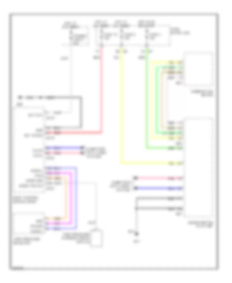
WARNING SYSTEMS
Chime Wiring Diagram, Coupe for Infiniti G35 x 2007


List of elements for Chime Wiring Diagram, Coupe for Infiniti G35 x 2007:
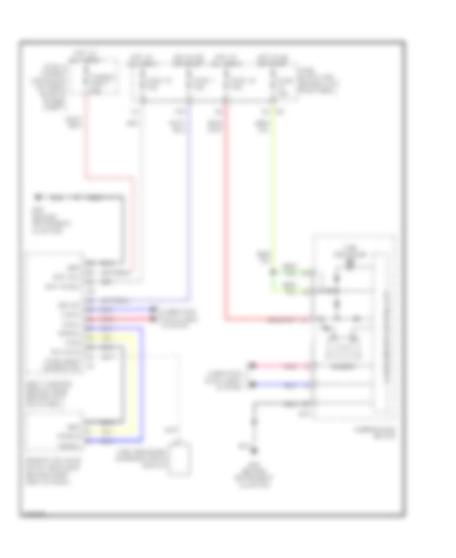
Chime Wiring Diagram, Sedan for Infiniti G35 x 2007
List of elements for Chime Wiring Diagram, Sedan for Infiniti G35 x 2007:
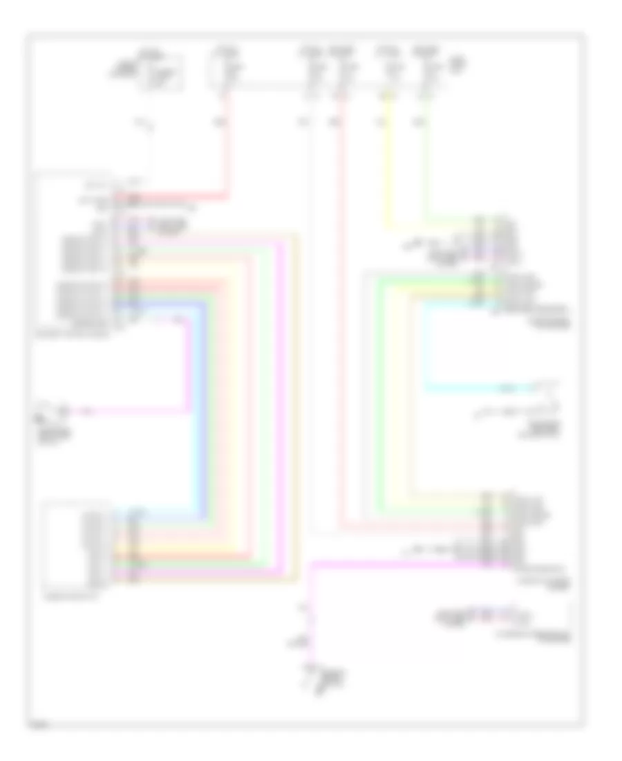
Tire Pressure Monitoring Wiring Diagram, Coupe for Infiniti G35 x 2007
List of elements for Tire Pressure Monitoring Wiring Diagram, Coupe for Infiniti G35 x 2007:
Tire Pressure Monitoring Wiring Diagram, Sedan for Infiniti G35 x 2007
List of elements for Tire Pressure Monitoring Wiring Diagram, Sedan for Infiniti G35 x 2007: