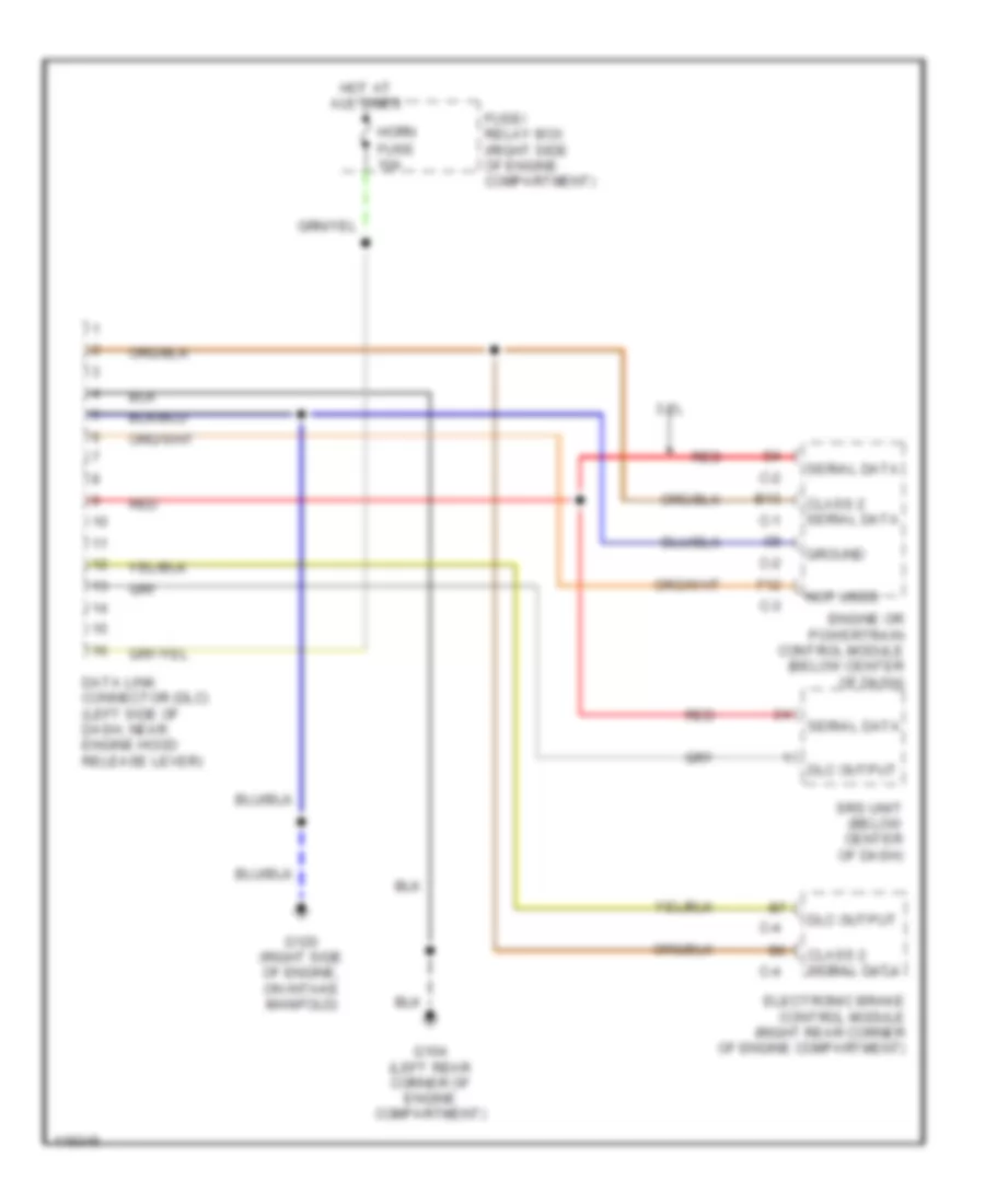
СИСТЕМА ПЕРЕДАЧИ ДАННЫХ
Электросхема компьютерной линии передачи данных CAN для Isuzu Rodeo S 1999
 https://portal-diagnostov.com/license.html
Automotive Electricians Portal FZCO
Automotive Electricians Portal FZCO
https://portal-diagnostov.com/license.html
https://portal-diagnostov.com/license.html
Automotive Electricians Portal FZCO
Automotive Electricians Portal FZCO
Электросхема компьютерной линии передачи данных CAN для Isuzu Rodeo S 1999 - Список элементов:
- 3.2l
- B13
- C-1
- C-2
- C-3
- C-4
- Class 2 serial data
- Data link connector (dlc) (left side of dash, near engine hood release lever)
- Dlc output
- Electronic brake control module (right rear corner of engine compartment)
- Engine or powertrain control module (below center of dash)
- F12
- Fuse 10a
- Fuse/ relay box (right side of engine compartment)
- G104 (left rear corner of engine compartment)
- G120 (right side of engine, on intake manifold)
- Ground
- Horn
- Hot at all times
- Not used
- Red
- Serial data
- Srs unit (below center of dash)
 Čeština
 Dansk
Dansk Deutsch
 Ελληνικά
 English
 English
 Español
 Suomi
Suomi Français
 Français
 עברית
עברית Hrvatski
 Magyar
 Italiano
 日本語
日本語 Nederlands
 Polski
 Português
 Português
 Română
 Русский
 Slovenčina
 Slovenščina
 Svenska
 Türkçe
 中文 (中国)
 한국어
한국어
