ENGINE PERFORMANCE
4.0L TURBO
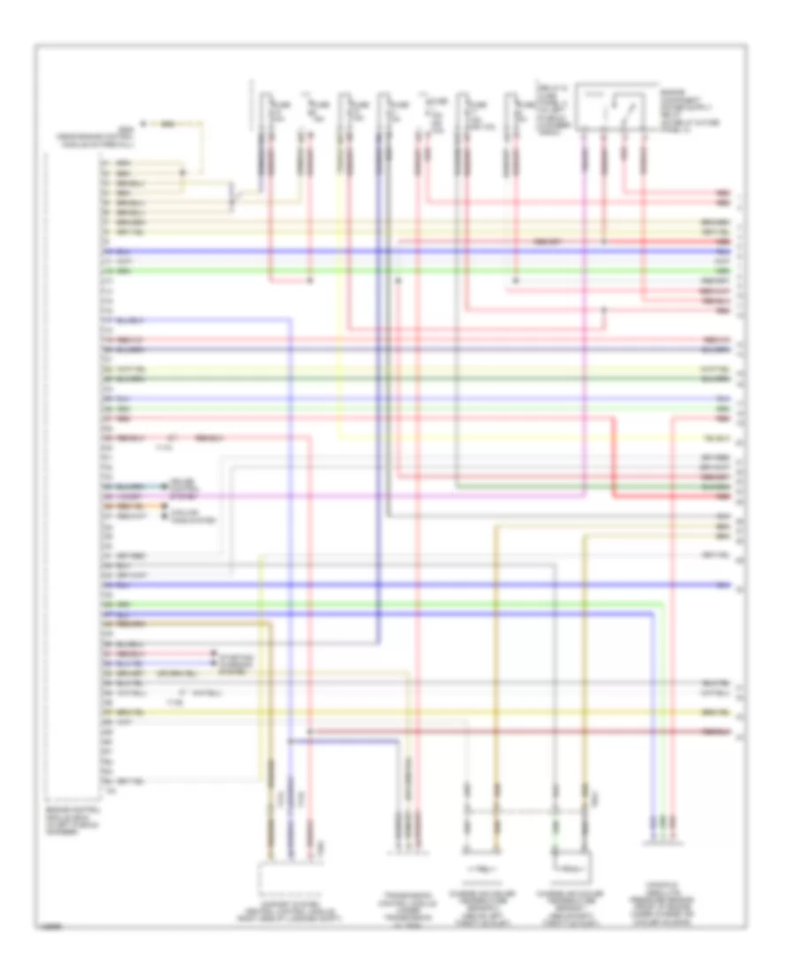
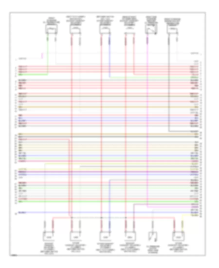
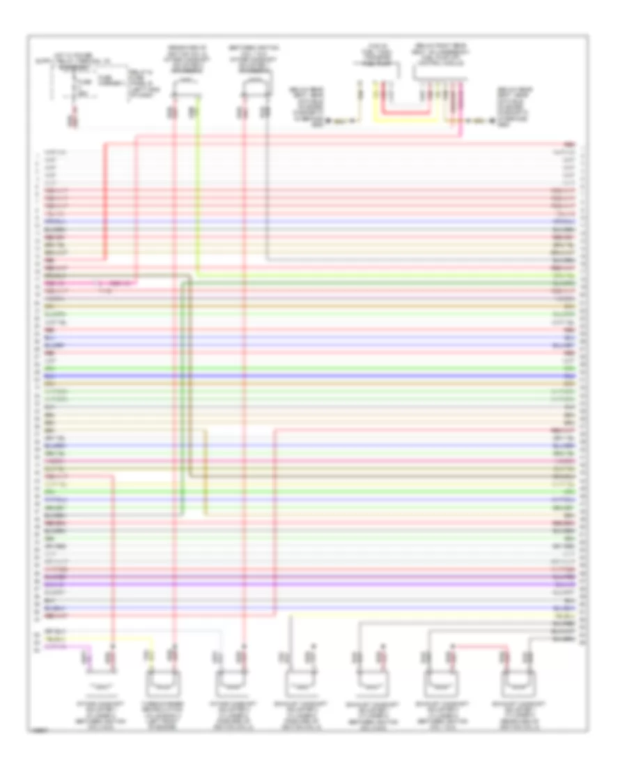
4.0L Turbo, Engine Performance Wiring Diagram (1 of 12) for Audi S6 2014
 https://portal-diagnostov.com/license.html
Automotive Electricians Portal FZCO
Automotive Electricians Portal FZCO
https://portal-diagnostov.com/license.html
https://portal-diagnostov.com/license.html
Automotive Electricians Portal FZCO
Automotive Electricians Portal FZCO
List of elements for 4.0L Turbo, Engine Performance Wiring Diagram (1 of 12) for Audi S6 2014:
- 10a
- 15a
- 17a
- Charge air cooler temperature sensor 1 (above right throttle inlet)
- Charge air cooler temperature sensor 2 (above left throttle inlet)
- Comfort system central control module (right side of luggage compt)
- Cooling fans system
- Cruise control system
- Engine control module (ecm) (in left plenum chamber)
- Fuse 15a
- Fuse 15a (or 10a)
- Fuse 5a
- Fuse n/a
- G645 (near engine control module on firewall)
- Manifold absolute pressure sensor (front of engine under charge air cooler housing)
- Red
- Relay & fuse panel a (in left plenum chamber e-box)
- Starting/ charging system
- T17a
- T17b
- T32g
- T8ay
- T91
- Transmission control module (under transmission oil pan)
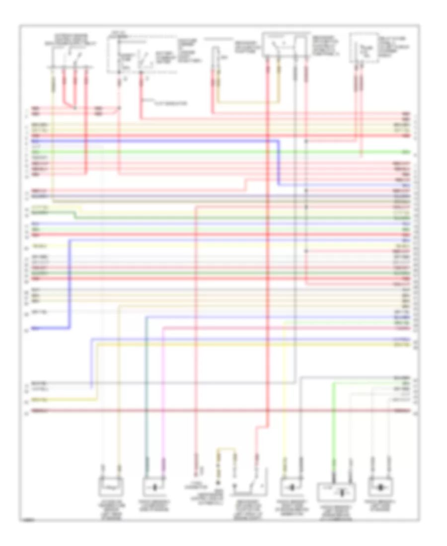
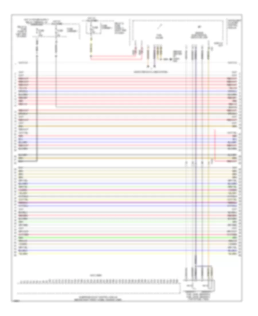
4.0L Turbo, Engine Performance Wiring Diagram (2 of 12) for Audi S6 2014
 https://portal-diagnostov.com/license.html
Automotive Electricians Portal FZCO
Automotive Electricians Portal FZCO
https://portal-diagnostov.com/license.html
https://portal-diagnostov.com/license.html
Automotive Electricians Portal FZCO
Automotive Electricians Portal FZCOList of elements for 4.0L Turbo, Engine Performance Wiring Diagram (2 of 12) for Audi S6 2014:
- 16a
- 17-pin connector
- 50a
- Battery interrupt igniter
- Flat conductor
- Fuse 15a
- G645 (near engine control module on firewall)
- Hot at all times
- Intake air temperature sensor (left rear of engine)
- Knock sensor 1 (right side of engine behind generator)
- Knock sensor 2 (lower right side of engine)
- Knock sensor 3 (left side of engine behind a/c compressor)
- Knock sensor 4 (left side of engine)
- Main fuse carrier (in luggage compt on battery)
- Nca
- Red
- Relay & fuse panel a (in left plenum chamber e-box)
- Safety fuse 150a
- Secondary air injection pump fuse
- Secondary air injection pump motor (left front of engine compt)
- Secondary air injection pump relay (on relay & fuse panel a)
- T17b
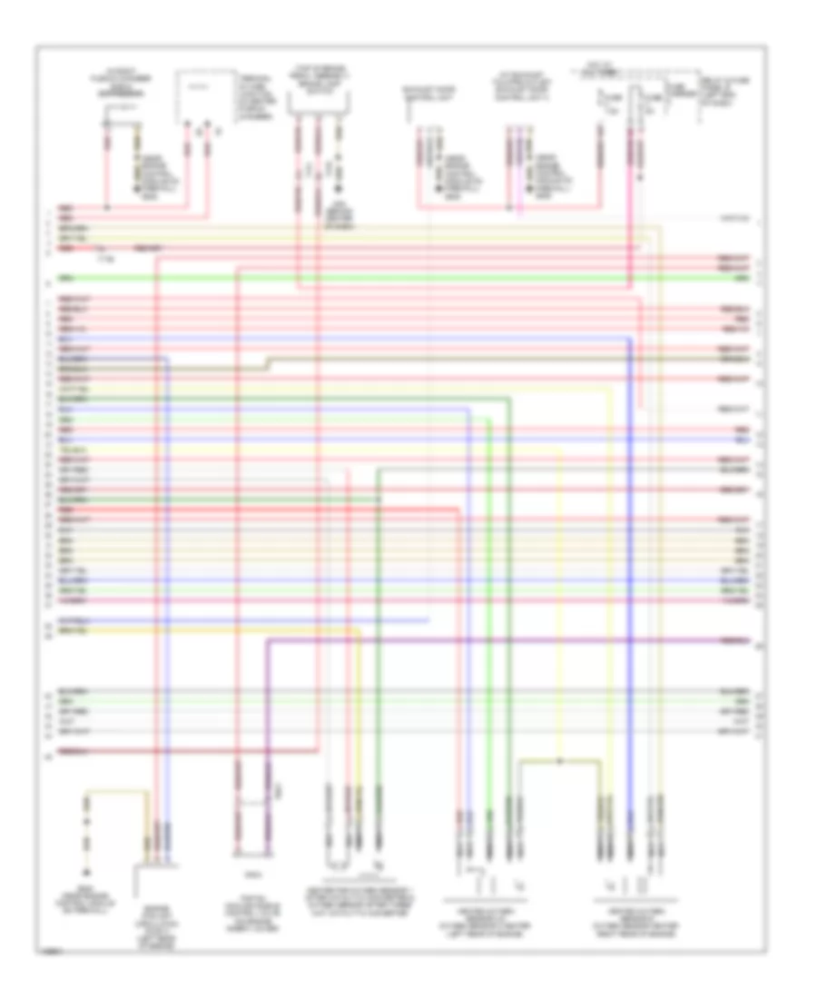
4.0L Turbo, Engine Performance Wiring Diagram (3 of 12) for Audi S6 2014
 https://portal-diagnostov.com/license.html
Automotive Electricians Portal FZCO
Automotive Electricians Portal FZCO
https://portal-diagnostov.com/license.html
https://portal-diagnostov.com/license.html
Automotive Electricians Portal FZCO
Automotive Electricians Portal FZCOList of elements for 4.0L Turbo, Engine Performance Wiring Diagram (3 of 12) for Audi S6 2014:
- (at exhaust tailpipe outlet) exhaust door control unit 2
- (in right plenum chamber e-box) suppressor
- (near engine control module on firewall) g645
- (top of brake pedal assembly) brake lamp switch
- Engine coolant circulation pump 2 (left rear of engine)
- Exhaust door control unit
- Fuse 5a
- Fuse 7.5a
- Fuse carrier
- G45 (behind center of dash)
- G645 (near engine control module on firewall)
- Heated oxygen sensor & oxygen sensor heater (right rear of engine)
- Heated oxygen sensor 2 & oxygen sensor 2 heater (left rear of engine)
- Heater for oxygen sensor 1 after catalytic converter & oxygen sensor after three way catalytic converter
- Hot at all times
- Nca
- Piston cooling nozzle control valve (on engine inner-v cover)
- Red
- Relay & fuse panel b (left end of dash)
- T17b
- T17i
- T17o
- T8ay
- Terminal 30 wire junction (in center plenum chamber)
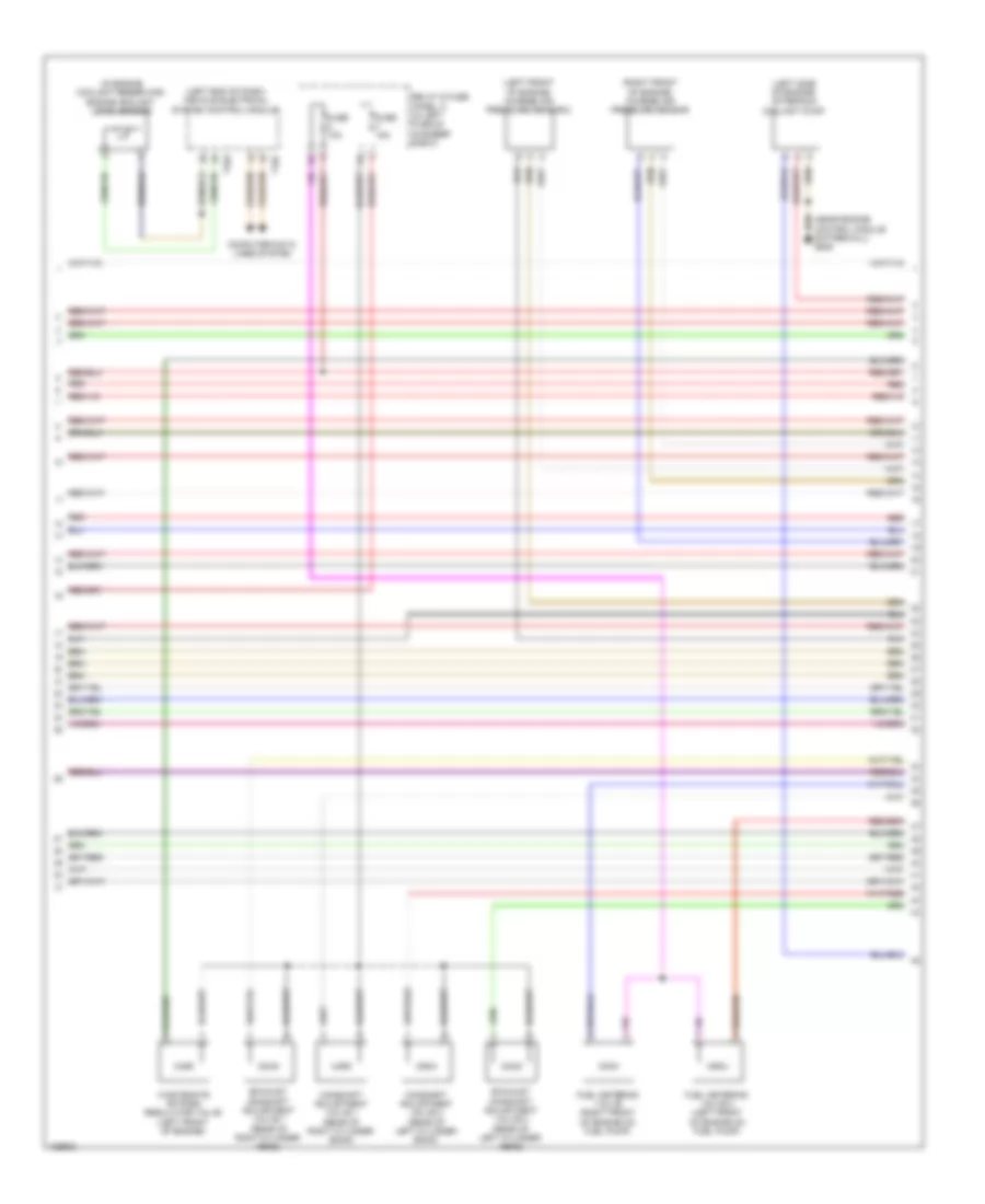
4.0L Turbo, Engine Performance Wiring Diagram (4 of 12) for Audi S6 2014
 https://portal-diagnostov.com/license.html
Automotive Electricians Portal FZCO
Automotive Electricians Portal FZCO
https://portal-diagnostov.com/license.html
https://portal-diagnostov.com/license.html
Automotive Electricians Portal FZCO
Automotive Electricians Portal FZCOList of elements for 4.0L Turbo, Engine Performance Wiring Diagram (4 of 12) for Audi S6 2014:
- (in engine coolant reservoir) engine coolant level sensor
- (left end of dash) vehicle electrical system control module
- (left front of engine) charge air pressure sensor 2
- (left side of engine) after-run coolant pump
- (near engine control module on firewall) g645
- (right front of engine) charge air pressure sensor
- Camshaft adjustment valve 1 (rear of right cylinder bank)
- Camshaft adjustment valve 2 (rear of left cylinder bank)
- Computer data lines system
- Exhaust camshaft adjustment valve 1 (rear of right cylinder head)
- Exhaust camshaft adjustment valve 2 (rear of left cylinder head)
- Fuel metering valve (right front of engine on fuel pump)
- Fuel metering valve 2 (left front of engine on fuel pump)
- Fuse 10a
- Fuse 15a
- Red
- Relay & fuse panel a (in left plenum chamber e-box)
- T16c
- T32a
- Wastegate bypass regulator valve (left front of engine)
4.0L Turbo, Engine Performance Wiring Diagram (5 of 12) for Audi S6 2014
 https://portal-diagnostov.com/license.html
Automotive Electricians Portal FZCO
Automotive Electricians Portal FZCO
https://portal-diagnostov.com/license.html
https://portal-diagnostov.com/license.html
Automotive Electricians Portal FZCO
Automotive Electricians Portal FZCOList of elements for 4.0L Turbo, Engine Performance Wiring Diagram (5 of 12) for Audi S6 2014:
- (between ignition coil 1 & 2) intake camshaft adjuster 2 cylinder 2
- (front of engine) engine coolant temperature sensor
- (front of engine) oil temperature sensor 2
- (next to cylinder 3 ignition coil) exhaust camshaft adjuster 2 cylinder 3
- (rear of right cylinder head) exhaust camshaft adjuster 1 cylinder 2
- (right side of engine) reduced oil pressure switch
- Exhaust camshaft adjuster 1 cylinder 3 (between ignition coil 2 & 3)
- Exhaust camshaft adjuster 2 cylinder 2 (next to cylinder 3 ignition coil)
- Intake camshaft adjuster 1 cylinder 2 (between ignition coil 2 & 3)
- Intake camshaft adjuster 1 cylinder 3 (between ignition coil 2 & 3)
- Intake camshaft adjuster 2 cylinder 3 (next to cylinder 3 ignition coil)
- Oil pressure switch (right side of engine)
- Red
4.0L Turbo, Engine Performance Wiring Diagram (6 of 12) for Audi S6 2014
 https://portal-diagnostov.com/license.html
Automotive Electricians Portal FZCO
Automotive Electricians Portal FZCO
https://portal-diagnostov.com/license.html
https://portal-diagnostov.com/license.html
Automotive Electricians Portal FZCO
Automotive Electricians Portal FZCOList of elements for 4.0L Turbo, Engine Performance Wiring Diagram (6 of 12) for Audi S6 2014:
- (behind center of dash) g45
- (not used)
- 15a
- Computer data lines system
- Display unit
- Engine electronics indicator lamp
- Fuel gauge
- Fuel level sensor & fuel level sensor 2 (top of fuel tank)
- Fuse 15a
- Fuse 5a
- Fuse carrier 1
- Hot at all times
- Instrument cluster control module
- Red
- Relay & fuse panel b (left end of dash)
- Relay & fuse panel c (right end of dash)
- Sensor 1
- Sensor 2
- Subframe mount control module (behind right front wheel housing liner)
- T17h
- T32
4.0L Turbo, Engine Performance Wiring Diagram (7 of 12) for Audi S6 2014
 https://portal-diagnostov.com/license.html
Automotive Electricians Portal FZCO
Automotive Electricians Portal FZCO
https://portal-diagnostov.com/license.html
https://portal-diagnostov.com/license.html
Automotive Electricians Portal FZCO
Automotive Electricians Portal FZCOList of elements for 4.0L Turbo, Engine Performance Wiring Diagram (7 of 12) for Audi S6 2014:
- (lower left of engine) subframe mount actuator 2
- (lower left of engine) subframe mount sensor 2
- (lower right of engine) subframe mount actuator 1
- (lower right of engine) subframe mount sensor 1
- Computer data lines system
- Digital sound system control module (left rear of luggage compt)
- Fuse 15a
- Fuse carrier
- G43 (behind right kick panel)
- Hot at all times
- Red
- Relay & fuse panel f (right rear of luggage compt)
- Subframe mount control module (behind right front wheel housing liner)
- T10an
- T17a
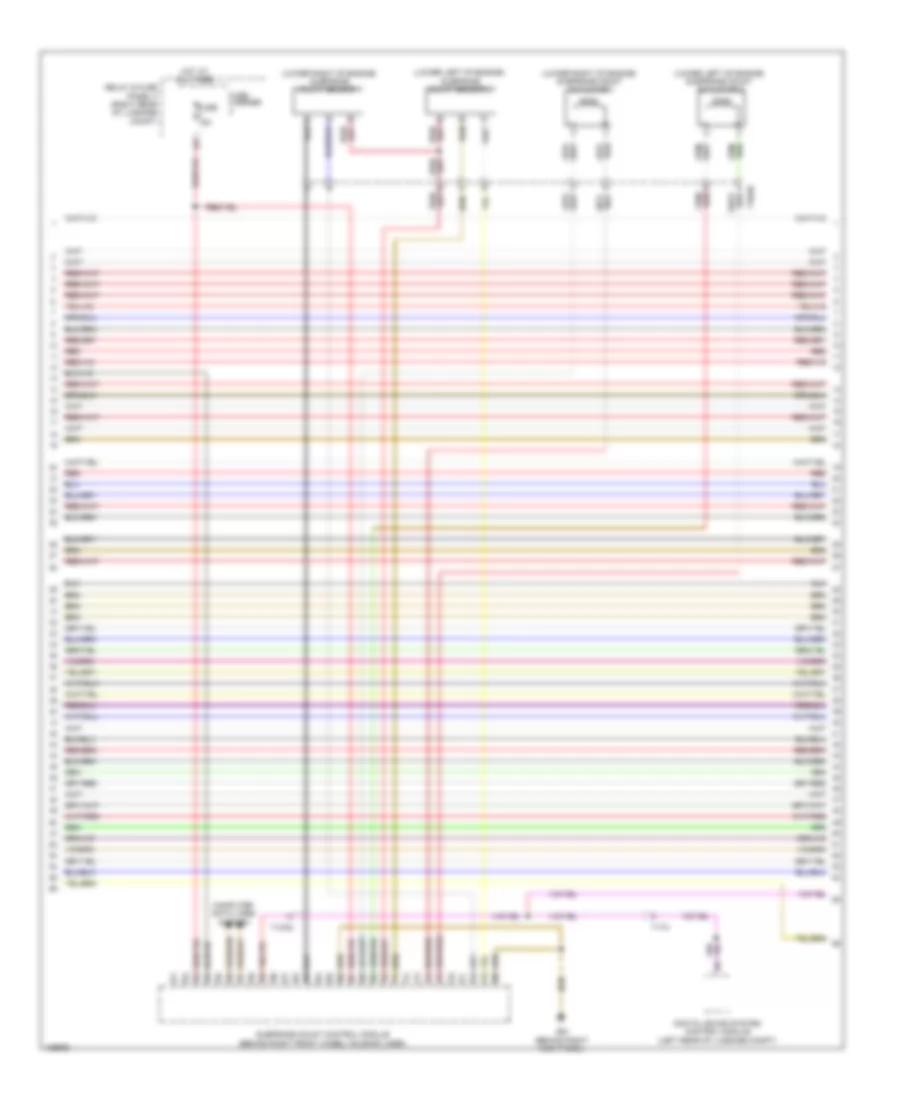
4.0L Turbo, Engine Performance Wiring Diagram (8 of 12) for Audi S6 2014
 https://portal-diagnostov.com/license.html
Automotive Electricians Portal FZCO
Automotive Electricians Portal FZCO
https://portal-diagnostov.com/license.html
https://portal-diagnostov.com/license.html
Automotive Electricians Portal FZCO
Automotive Electricians Portal FZCOList of elements for 4.0L Turbo, Engine Performance Wiring Diagram (8 of 12) for Audi S6 2014:
- (on lower left hose on radiator) engine coolant temperature sensor on radiator outlet
- (rear of right intake manifold cylinder bank) intake manifold runner position sensor
- (top front of engine, on throttle body assembly) throttle valve control module
- Fuel injector cylinders 1, 2, 3, 4, 5, 6, 7 & 8
- Red
- T105 engine control module (ecm) (in left plenum chamber)
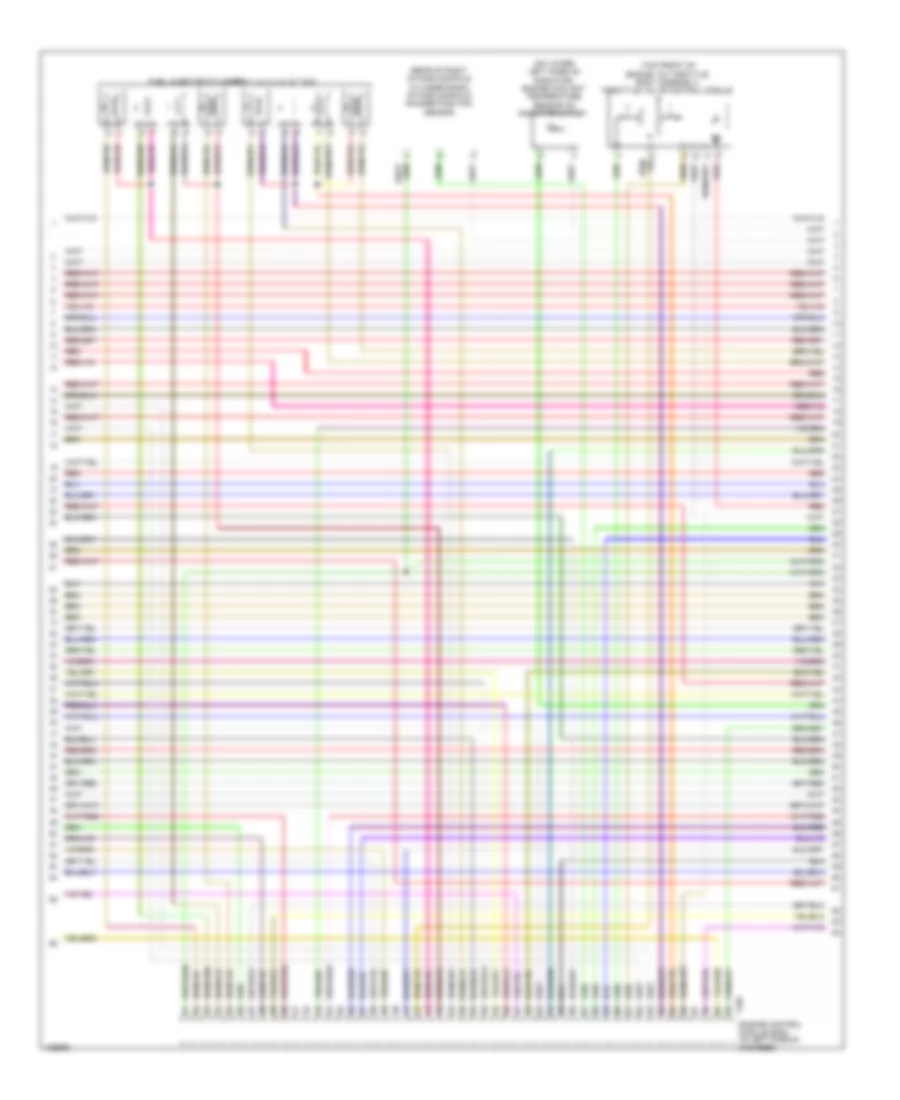
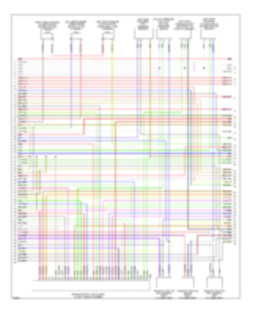
4.0L Turbo, Engine Performance Wiring Diagram (9 of 12) for Audi S6 2014
 https://portal-diagnostov.com/license.html
Automotive Electricians Portal FZCO
Automotive Electricians Portal FZCO
https://portal-diagnostov.com/license.html
https://portal-diagnostov.com/license.html
Automotive Electricians Portal FZCO
Automotive Electricians Portal FZCOList of elements for 4.0L Turbo, Engine Performance Wiring Diagram (9 of 12) for Audi S6 2014:
- (below rear seat, near data bus on board diagnostic interface) g688
- (below right rear seat, on underbody) fuel pump (fp) control module
- (between ignition coil 7 & 8) intake camshaft adjuster 1 cylinder 8
- (rearward of ignition coil 8) intake camshaft adjuster 2 cylinder 8
- (top of fuel tank) transfer fuel pump
- Exhaust camshaft adjuster 1 cylinder 5 (between ignition coil 5 & 6)
- Exhaust camshaft adjuster 1 cylinder 8 (rearward of ignition coil 8)
- Exhaust camshaft adjuster 2 cylinder 5 (forward of ignition coil 5)
- Exhaust camshaft adjuster 2 cylinder 8 (between ignition coil 7 & 8)
- Fuse 25a
- Fuse carrier 3
- Intake camshaft adjuster 1 cylinder 5 (between ignition coil 5 & 6)
- Intake camshaft adjuster 2 cylinder 5 (forward of ignition coil 5)
- Red
- Relay & fuse panel b (leftt end of dash)
- T17b
- Turbocharger recirculation valve bank 2 (left front of engine)
4.0L Turbo, Engine Performance Wiring Diagram (10 of 12) for Audi S6 2014
 https://portal-diagnostov.com/license.html
Automotive Electricians Portal FZCO
Automotive Electricians Portal FZCO
https://portal-diagnostov.com/license.html
https://portal-diagnostov.com/license.html
Automotive Electricians Portal FZCO
Automotive Electricians Portal FZCOList of elements for 4.0L Turbo, Engine Performance Wiring Diagram (10 of 12) for Audi S6 2014:
- (left front of engine compt) secondary air
- (left front of engine) intake manifold runner position sensor 2
- (left side of engine) evap canister purge regulator valve 1
- (left side of engine) fuel pressure sensor 2
- (on high pressure fuel pump) low fuel pressure sensor
- (on turbocharger) turbocharger recirculation valve
- (right side of engine) intake manifold runner control valve
- Camshaft position (cmp) sensor 2 (left cylinder head)
- Camshaft position (cmp) sensor 4 (right cylinder head)
- Camshaft position sensor (right cylinder head)
- Engine control module (ecm) (in left plenum chamber)
- Injection sensor 1
- Red
- T105
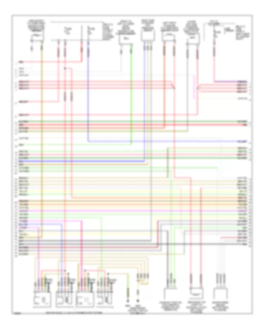
4.0L Turbo, Engine Performance Wiring Diagram (11 of 12) for Audi S6 2014
 https://portal-diagnostov.com/license.html
Automotive Electricians Portal FZCO
Automotive Electricians Portal FZCO
https://portal-diagnostov.com/license.html
https://portal-diagnostov.com/license.html
Automotive Electricians Portal FZCO
Automotive Electricians Portal FZCOList of elements for 4.0L Turbo, Engine Performance Wiring Diagram (11 of 12) for Audi S6 2014:
- (above right cylinder head) engine cover temperature sensor
- (front of left cylinder bank) engine temperature control sensor
- (left front of engine) cylinder head coolant valve
- (lower left side of engine) oil pressure regulation valve
- (right side of engine) fuel pressure sensor
- 14a
- Camshaft position (cmp) sensor 3 (under coolant reservoir)
- Engine speed sensor (bottom rear of engine)
- Fuse 30a
- Fuse 5a
- Fuse carrier
- G600
- G645 (near engine control module on firewall)
- Hot at all times
- Ignition coils 1, 2, 3 & 4 w/ power output stage
- Nca
- Red
- Relay & fuse panel a (in left plenum chamber e-box)
- Relay & fuse panel f (right rear of luggage compt)
- Secondary air injection solenoid valve 2 (left front of engine)
- Spark plug
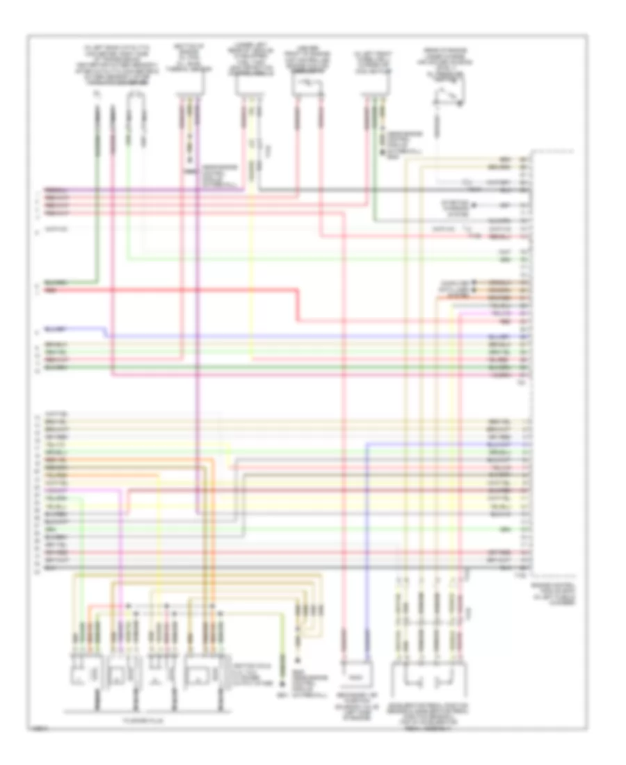
4.0L Turbo, Engine Performance Wiring Diagram (12 of 12) for Audi S6 2014
 https://portal-diagnostov.com/license.html
Automotive Electricians Portal FZCO
Automotive Electricians Portal FZCO
https://portal-diagnostov.com/license.html
https://portal-diagnostov.com/license.html
Automotive Electricians Portal FZCO
Automotive Electricians Portal FZCOList of elements for 4.0L Turbo, Engine Performance Wiring Diagram (12 of 12) for Audi S6 2014:
- (bottom of engine oil pan) oil level thermal sensor
- (center front of engine) map controlled engine cooling thermostat
- (in left bank catalytic converter, right side of transmission) heater for oxygen sensor 2 after catalytic converter & oxygen sensor 2 after catalytic converter
- (in left front wheelwell) charge air cooling pump
- (near engine control module on firewall)
- (near engine control module on firewall) g645
- (rear of engine under charge air cooler housing) level 3 oil pressure switch
- (under left rear of vehicle) (if equipped) fuel tank leak detection control module
- Accelerator pedal position sensor & accelerator pedal position sensor 2 (top of accelerator pedal assembly)
- Computer data lines system
- Engine control module (ecm) (in left plenum chamber)
- G601
- G645
- G645 (near engine control module on firewall)
- Ignition coils 5, 6, 7 & 8 w/ power output stage
- Nca
- Red
- Secondary air injection solenoid valve (left side of engine)
- Starting/ charging system
- T105
- T17a
- T17b
- T17h
- T8ay
- T91
- To spark plug

 Čeština
 Dansk
Dansk Deutsch
 Ελληνικά
 English
 English
 Español
 Suomi
Suomi Français
 Français
 עברית
עברית Hrvatski
 Magyar
 Italiano
 日本語
日本語 Nederlands
 Polski
 Português
 Português
 Română
 Русский
 Slovenčina
 Slovenščina
 Svenska
 Türkçe
 中文 (中国)
