🚀 Welcome to the Launch of DiagnostData.com!

The new database is currently being populated with wiring diagrams up to 2024.

AUTOMOTIVE ELECTRICIANS PORTAL

WARNING SYSTEMS – Audi Q5 Premium 2014 – SYSTEM WIRING DIAGRAMS

WARNING SYSTEMS

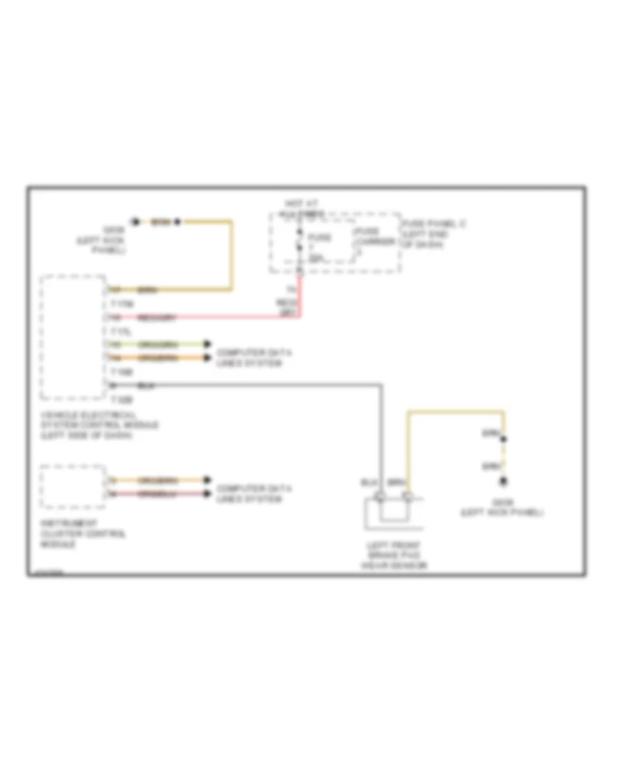
Brake Wear Sensor Wiring Diagram for Audi Q5 Premium 2014

Brake Wear Sensor Wiring Diagram for Audi Q5 Premium 2014 https://portal-diagnostov.com/license.html
https://portal-diagnostov.com/license.html Automotive Electricians Portal FZCO Automotive Electricians Portal FZCO
Download PDF file

List of elements for Brake Wear Sensor Wiring Diagram for Audi Q5 Premium 2014:

  • Computer data lines system
  • Fuse 20a
  • Fuse carrier
  • Fuse panel c (left end of dash)
  • G639 (left kick panel)
  • Hot at all times
  • Instrument cluster control module
  • Left front brake pad wear sensor
  • T16b
  • T17l
  • T17m
  • T32b
  • Vehicle electrical system control module (left side of dash)

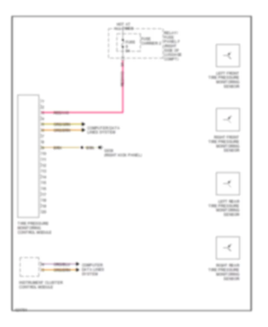
Tire Pressure Monitoring Wiring Diagram for Audi Q5 Premium 2014

Tire Pressure Monitoring Wiring Diagram for Audi Q5 Premium 2014 https://portal-diagnostov.com/license.html
https://portal-diagnostov.com/license.html Automotive Electricians Portal FZCO Automotive Electricians Portal FZCO
모든 배선 다이어그램에 액세스하십시오.Download PDF file

List of elements for Tire Pressure Monitoring Wiring Diagram for Audi Q5 Premium 2014:

  • Computer data lines system
  • Fuse 5a
  • Fuse carrier 2
  • G638 (right kick panel)
  • Hot at all times
  • Instrument cluster control module
  • Left front tire pressure monitoring sensor
  • Left rear tire pressure monitoring sensor
  • Relay/ fuse panel f (right side of luggage compt)
  • Right front tire pressure monitoring sensor
  • Right rear tire pressure monitoring sensor
  • Tire pressure monitoring control module