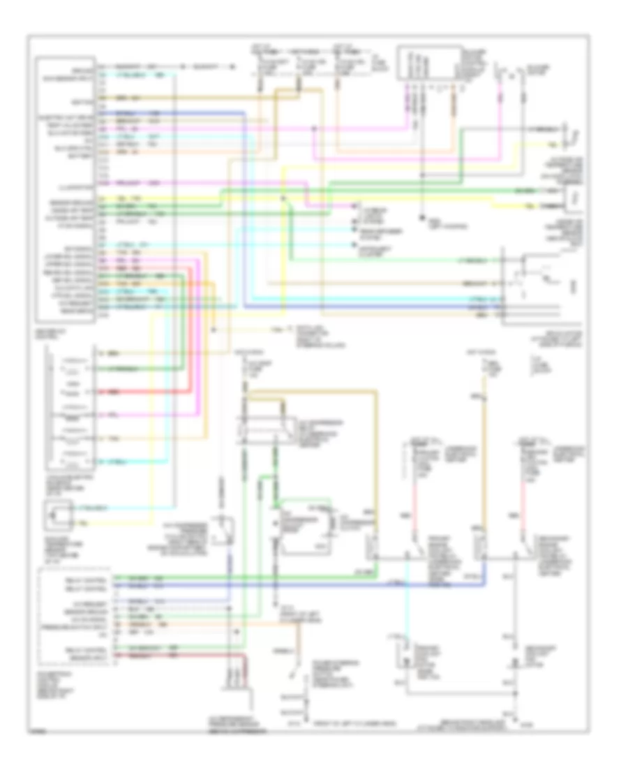
AIR CONDITIONING
Air Conditioning Wiring Diagrams for Cadillac Fleetwood 1995
 https://portal-diagnostov.com/license.html
Automotive Electricians Portal FZCO
Automotive Electricians Portal FZCO
https://portal-diagnostov.com/license.html
https://portal-diagnostov.com/license.html
Automotive Electricians Portal FZCO
Automotive Electricians Portal FZCO
List of elements for Air Conditioning Wiring Diagrams for Cadillac Fleetwood 1995:
- (behind compressor)
- (behind right headlamp
- (front of left
- (front of left cylinder head)
- +5v
- 40a
- A/c comp fuse 10a
- A/c compressor clutch
- A/c compressor clutch diode
- A/c compressor pressure cycling switch (right rear of engine compartment, on accumulator)
- A/c compressor relay (in underhood electrical center)
- A/c on signal
- A/c refrigerant pressure sensor
- A/c request
- Air mix motor (attached to left side of plenum)
- Attached to radiator support)
- Batt
- Battery
- Blower motor
- Blower motor control module (right i/p)
- Blw ctrl
- Blw motor fdbk
- Blw spd ctrl
- C1 a
- C10
- C11
- C12
- C13
- C14
- C15
- C16
- Ctrl sig
- Cylinder head)
- D10
- D11
- D12
- D13
- D14
- D15
- D16
- Data link connector (right of steering column)
- Def sol signal
- Dlc data link
- E/m signal
- Electric act drive
- G109
- G112
- G200 (left kickpad)
- Gen fuse 10a
- Ground
- Heater-a/c control
- Hot at all times
- Hot in run
- Htr sol signal
- Hvac bat fuse 10a
- Hvac ign fuse 10a
- Hvac mdl fuse 25a
- I/p fuse block
- Ignition
- Illumination
- Inside air temp
- Inside air temperature sensor (above glove box)
- Instrument cluster
- Interior lights system
- Logic
- Lower sol signal
- Nca
- Outside air temp
- Outside air temperature sensor (on hood latch support)
- Power steering pressure switch (near power steering unit)
- Powertrain control module (behind right side of i/p)
- Pressure switch input
- Primary clg fan maxi fuse
- Primary coolant fan motor (base and v03)
- Primary engine coolant fan relay (underhood electrical center) (base and v03)
- Rear defog
- Rear defogger system
- Recirc sol signal
- Red
- Relay control
- Second- ary clg fan maxi fuse
- Secondary coolant fan motor
- Secondary engine coolant fan relay (underhood electrical center)
- Sensor ground
- Sensor input
- Sun sensor input
- Sunload temperature sensor (top center of i/p)
- Tan
- Temp valve fdbk
- Underhood electrical center
- Upper sol signal
- Vacuum/electric solenoid (near center of i/p)
- Vf dim signal
 Čeština
 Dansk
Dansk Deutsch
 Ελληνικά
 English
 English
 Español
 Suomi
Suomi Français
 Français
 עברית
עברית Hrvatski
 Magyar
 Italiano
 日本語
日本語 Nederlands
 Polski
 Português
 Português
 Română
 Русский
 Slovenčina
 Slovenščina
 Svenska
 Türkçe
 中文 (中国)
 한국어
한국어
