AIR CONDITIONING
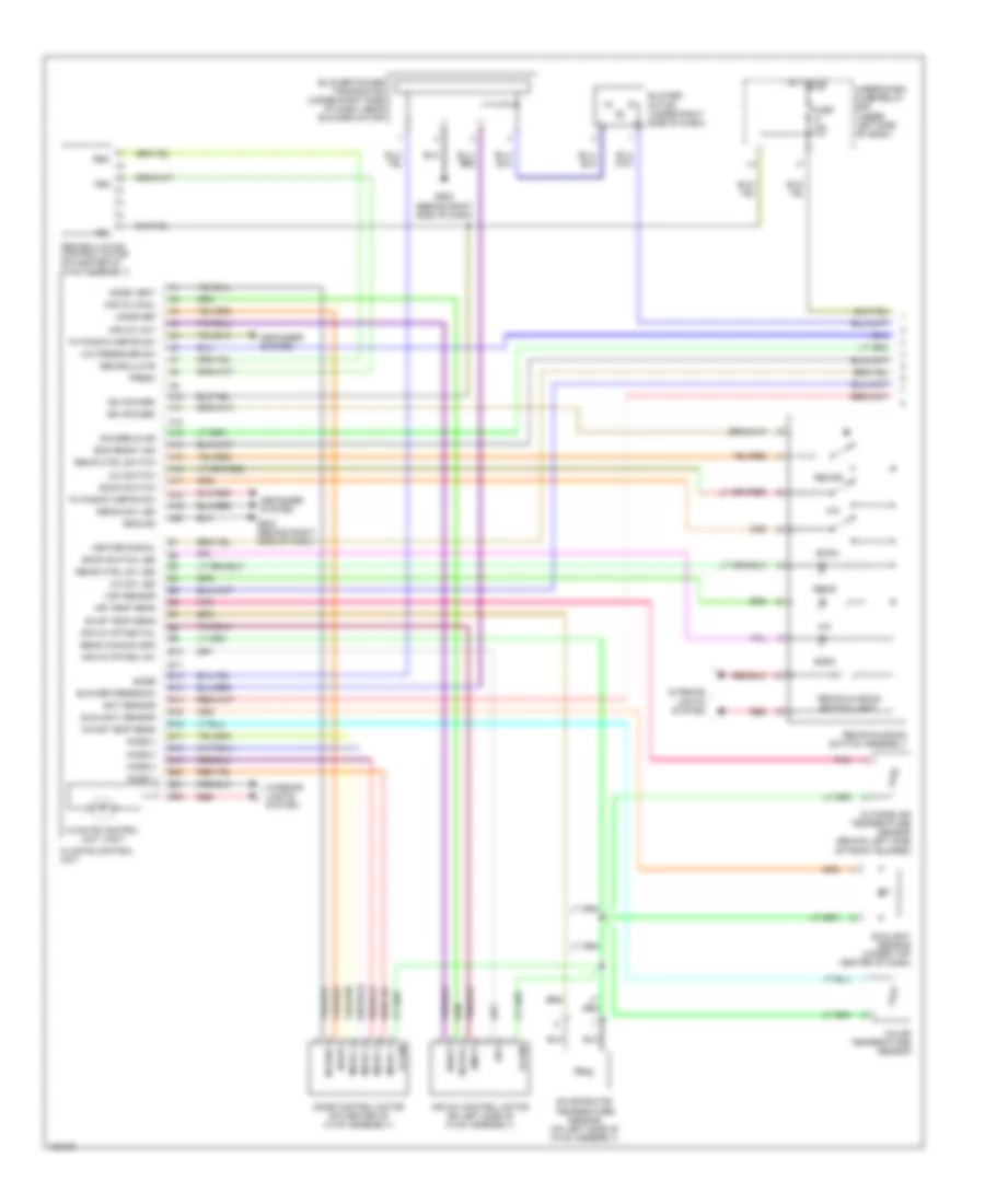
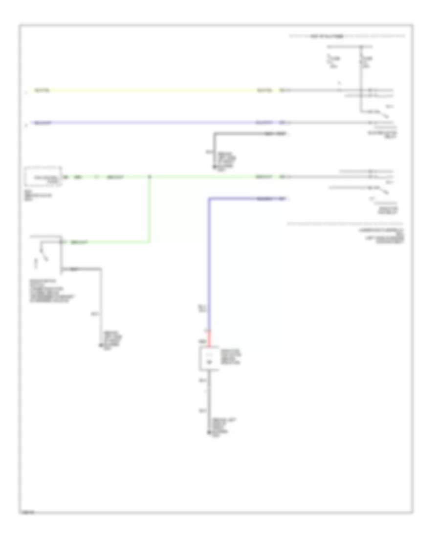
Automatic A/C Wiring Diagram, Hybrid (1 of 2) for Honda Civic 2005
 https://portal-diagnostov.com/license.html
Automotive Electricians Portal FZCO
Automotive Electricians Portal FZCO
https://portal-diagnostov.com/license.html
https://portal-diagnostov.com/license.html
Automotive Electricians Portal FZCO
Automotive Electricians Portal FZCO
List of elements for Automatic A/C Wiring Diagram, Hybrid (1 of 2) for Honda Civic 2005:
- A/c
- A/c pressure sw
- A/c sw led
- A/c switch
- A10
- A11
- A12
- A13
- A14
- A15
- A16
- A17
- A18
- A19
- A20
- Air mix control motor (on left side of hvac assembly)
- Air mix cool
- Air mix hot
- Air mix poten +5v
- Air mix potential
- Air temp sens
- Amd-p
- B10
- B11
- B12
- B13
- B14
- B15
- B16
- B17
- B18
- B19
- B20
- B21
- B22
- Base
- Blower feedback
- Blower motor (under right side of dash)
- Blower power transistor (under right side of dash, near blower motor)
- Climate control unit
- Climate control unit light
- Defog sw led
- Defogger system
- Econ
- Econ switch
- Econ switch led
- Ect sensor
- Eng ready sig
- Evap temp sens
- Evaporator
- Fresh
- Frs
- Fuse 10a
- G502 (behind right side of dash)
- Gauges & ind
- Ground
- Heater signal
- Hot in on
- Ig2
- Ig2 (power)
- Ign (power)
- In-car temp sens
- In-car temperature sensor
- Interior lights system
- M-cool
- M-def
- M-hot
- M-vent
- Mode 1
- Mode 2
- Mode 3
- Mode 4
- Mode control motor (on center of hvac assembly)
- Mode def
- Mode vent
- Outside air temperature sensor (behind left side of front bumper)
- Pnk
- R window defog sw
- Rec
- Recir
- Recir ctrl sw led
- Recir ctrl switch
- Recir-a/c-econ switch assembly
- Recir-a/c-econ switch light
- Recirc
- Recirculate
- Recirculation control motor (on center of hvac assembly)
- Red
- S-com
- S5v
- Sens common gnd
- Sunlight sensor
- Sunlight sensor (under top center of dash)
- Temperature sensor (on left side of hvac assembly)
- Under-dash fuse/relay box (under left side of dash)
- Vsp sensor
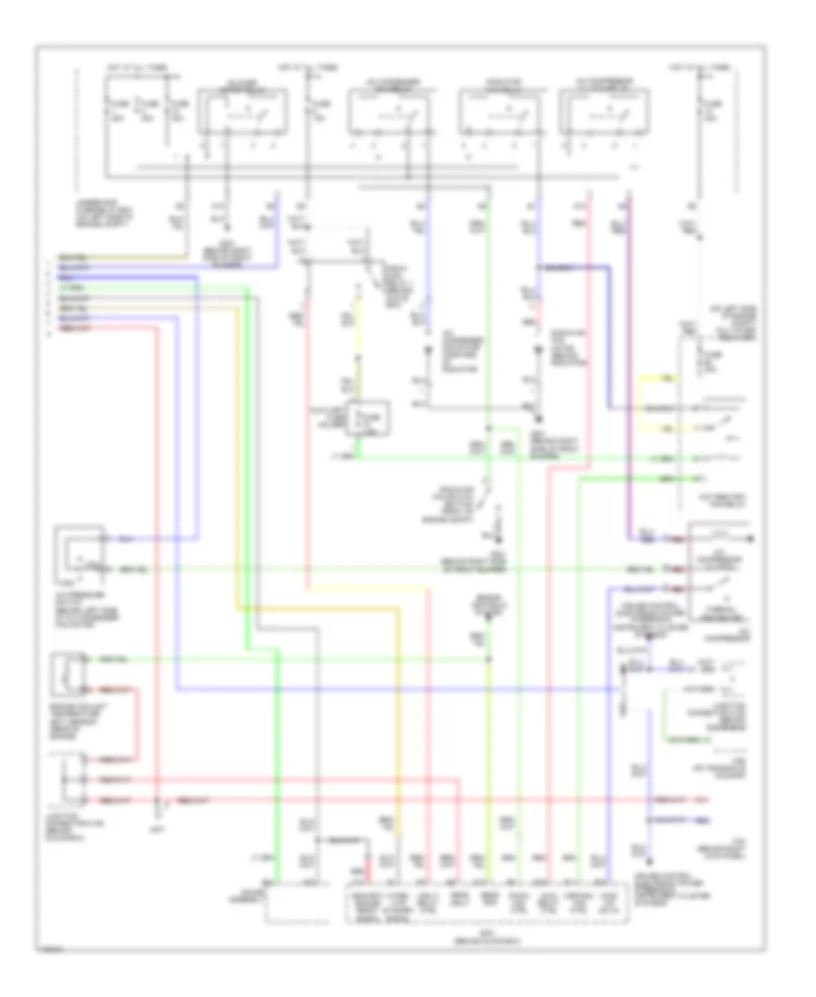
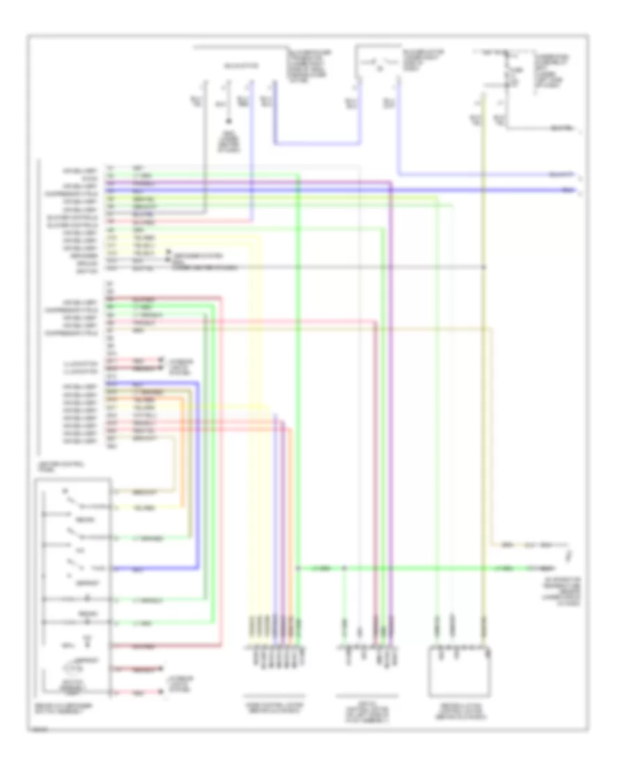
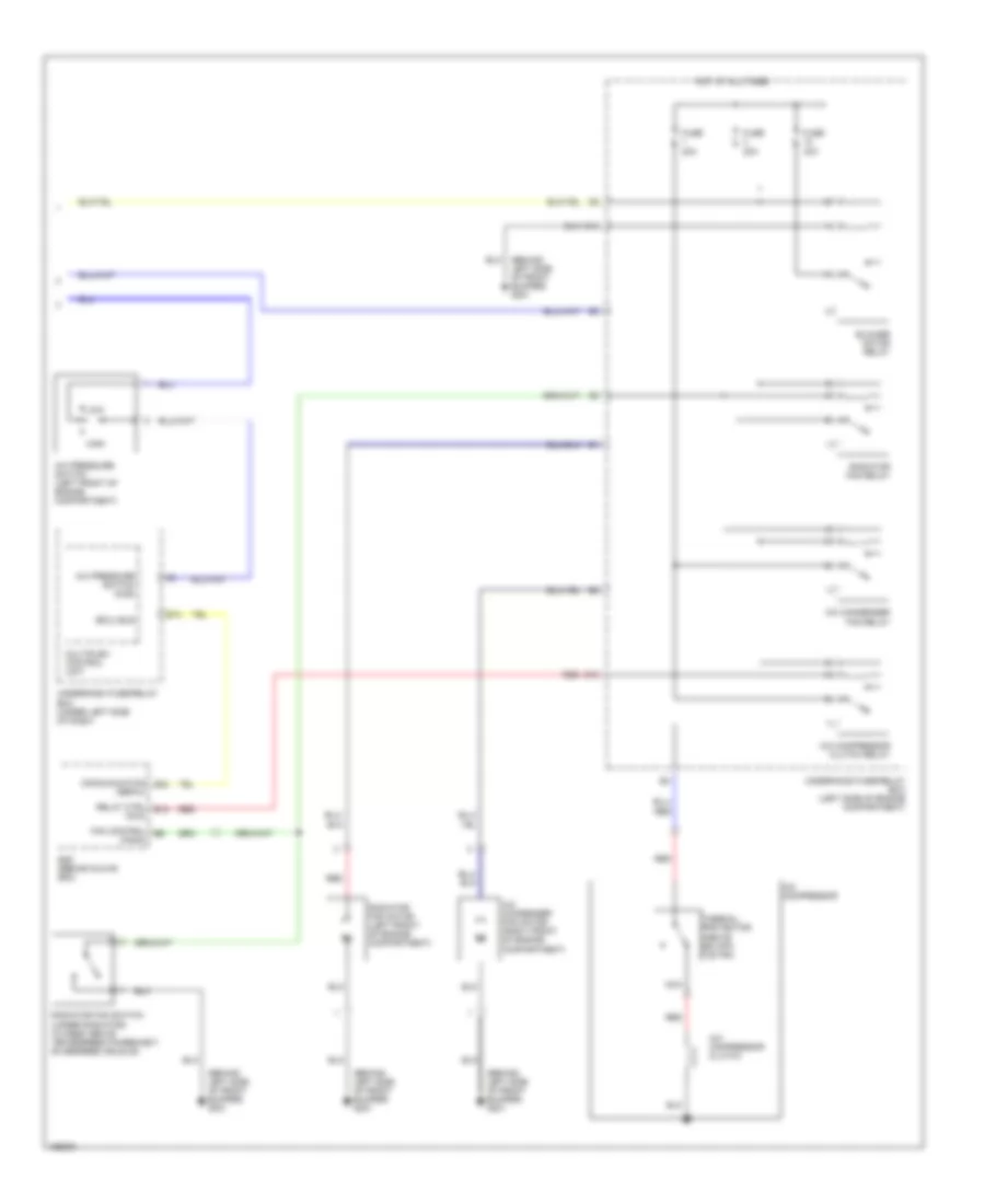
Automatic A/C Wiring Diagram, Hybrid (2 of 2) for Honda Civic 2005
 https://portal-diagnostov.com/license.html
Automotive Electricians Portal FZCO
Automotive Electricians Portal FZCO
https://portal-diagnostov.com/license.html
https://portal-diagnostov.com/license.html
Automotive Electricians Portal FZCO
Automotive Electricians Portal FZCOList of elements for Automatic A/C Wiring Diagram, Hybrid (2 of 2) for Honda Civic 2005:
- (acc) relay ctrl
- (acs) a/c sw in
- (eng rdy) engine ready signal
- (fanc) fan ctrl
- (hrfanc) fan ctrl
- (htrs) htr standby signal
- (mrly) relay ctrl
- (on left side of engine compt) multi-fuse/ relay box
- A/c compressor
- A/c compressor clutch
- A/c compressor clutch relay
- A/c condenser fan motor (forward of radiator)
- A/c condenser fan relay
- A/c pressure switch (behind left side of a/c condenser fan motor)
- A10
- A20
- Auxiliary fuse holder
- B14
- B22
- Blower motor relay
- C11
- C13
- Cruise control electronic power steering & instrument cluster systems
- Cvt
- Cvt cvt
- D10
- D13
- E11
- E18
- E28
- Ecm (behind glove box)
- Engine controls system
- Engine coolant temperature (ect) sensor (rear of engine)
- Fuse 15a
- Fuse 20a
- Fuse 40a
- Fuse 7.5a
- G201 (behind right side of front bumper)
- Gauge assembly
- High
- Hot at all times
- Hot restart fan relay
- Junction connector c106 (behind glove box)
- Low
- M m
- M/t
- Pgm-fi main relay 1 (behind glove box)
- Radiator fan motor (behind radiator)
- Radiator fan relay
- Radiator fan switch (bottom front of engine compt)
- Red
- Sens gnd
- Sens input
- Tcm (behind right kick panel)
- Thermal protector
- Underhood fuse/relay box (on left side of engine compt)
- Vss (on transaxle housing)
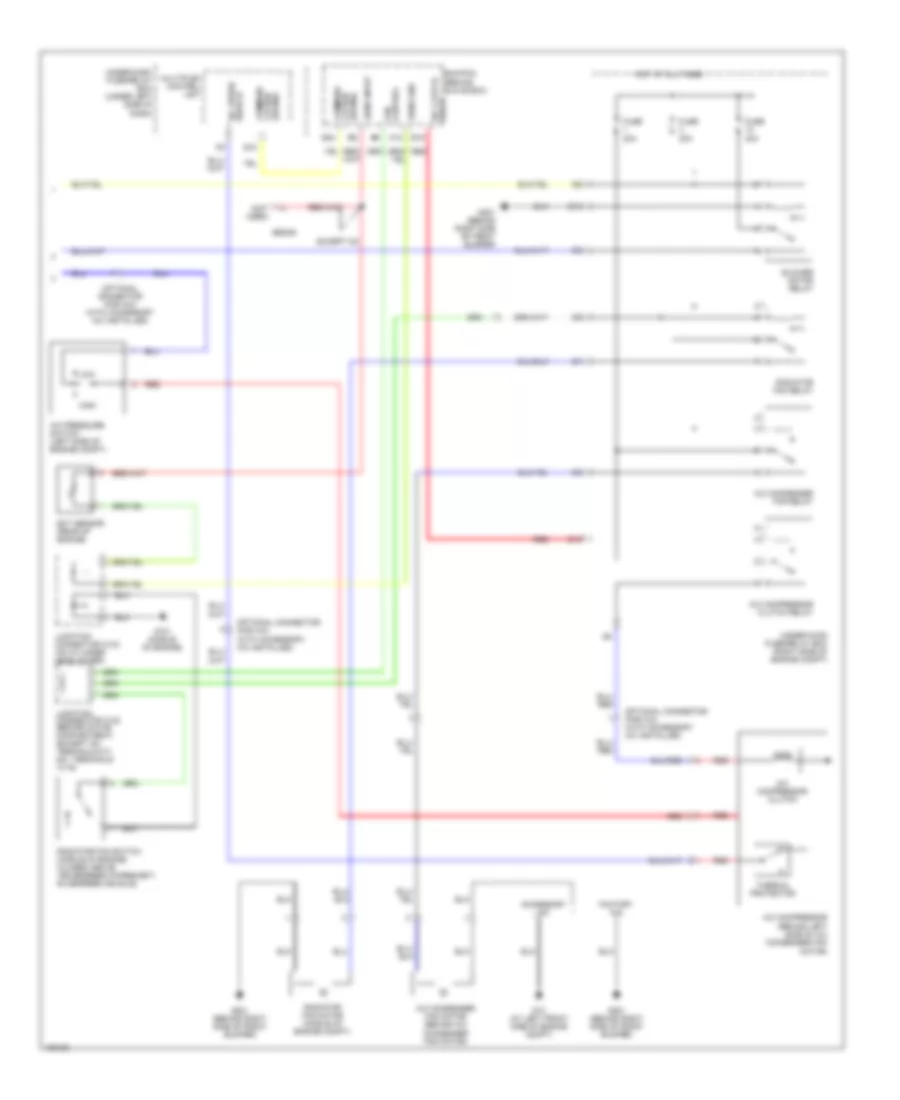
Heater Wiring Diagram, Except Hatchback & Hybrid for Honda Civic 2005
 https://portal-diagnostov.com/license.html
Automotive Electricians Portal FZCO
Automotive Electricians Portal FZCO
https://portal-diagnostov.com/license.html
https://portal-diagnostov.com/license.html
Automotive Electricians Portal FZCO
Automotive Electricians Portal FZCOList of elements for Heater Wiring Diagram, Except Hatchback & Hybrid for Honda Civic 2005:
- A10
- A11
- A12
- A13
- A14
- Air delivery
- Air mix control motor (on left side of hvac assembly)
- Amd-p
- B10
- B11
- B12
- B13
- B14
- B15
- B16
- B17
- B18
- B19
- B20
- B21
- B22
- Blower controls
- Blower motor (under right side of dash)
- Blower motor relay
- Blower power transistor (under right side of dash, near blower motor)
- D13
- Defogger
- Defogger system
- Defrost
- Frs
- Fuse 10a
- Fuse 40a
- G201 (behind right side of front bumper)
- G502 (under center of dash)
- Ground
- Heater control panel
- Hot at all times
- Hot in on
- Ig2
- Ignition
- Illumination
- Interior lights system
- M-cool
- M-def
- M-hot
- M-vent
- Manual a/c circuit
- Mode control motor (behind glove box)
- Mode-1
- Mode-2
- Mode-3
- Mode-4
- Rec
- Recirc
- Recirc defogger switch assembly
- Recirculation control motor (behind glove box)
- Red
- S-com
- S5v
- Scom
- Solid state
- Switch assembly light
- Under-dash fuse/relay box (under left side of dash)
- Under-hood fuse/relay box (right side of engine compt)
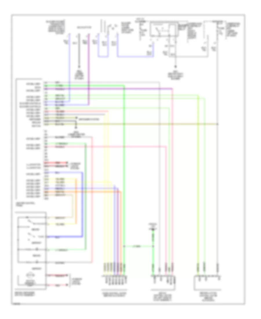
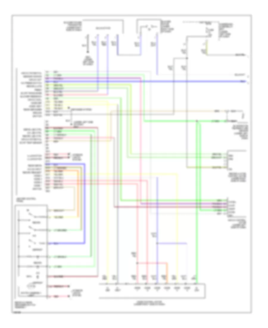
Heater Wiring Diagram, Hatchback (1 of 2) for Honda Civic 2005
 https://portal-diagnostov.com/license.html
Automotive Electricians Portal FZCO
Automotive Electricians Portal FZCO
https://portal-diagnostov.com/license.html
https://portal-diagnostov.com/license.html
Automotive Electricians Portal FZCO
Automotive Electricians Portal FZCOList of elements for Heater Wiring Diagram, Hatchback (1 of 2) for Honda Civic 2005:
- (under left side of dash) g501
- A10
- A11
- A12
- A13
- A14
- Air mix control motor (under left side of dash)
- Air mix cool
- Air mix hot
- Air mix potental
- Air mix potential
- Amd-p
- B10
- B11
- B12
- B13
- B14
- B15
- B16
- B17
- B18
- B19
- B20
- B21
- B22
- Blower feedback
- Blower motor (under right side of dash)
- Blower power transistor (under right side of dash)
- Blwr trans base
- Defog led ctrl
- Defogger system
- Defrost
- Fresh
- Frs
- Fuse 10a
- G501 (under left side of dash)
- Ground
- Heater control panel
- Hot in on
- Ig2
- Ignition
- Illumination
- Interior lights system
- M- def
- M- vent
- M-cool
- M-hot
- Mode -1
- Mode -2
- Mode -3
- Mode -4
- Mode 1
- Mode 2
- Mode 3
- Mode 4
- Mode control motor (under right side of dash)
- Mode def
- Mode vent
- Rear defog
- Rear defogger
- Rec
- Recir-a/c rear defogger switch assembly
- Recirc
- Recirculate
- Recirculation control motor (under right side of dash)
- Red
- S- com
- S-com
- S5v
- Sensor common
- Solid state
- Switch light assembly
- Underdash fuse/relay box (under left side of dash)
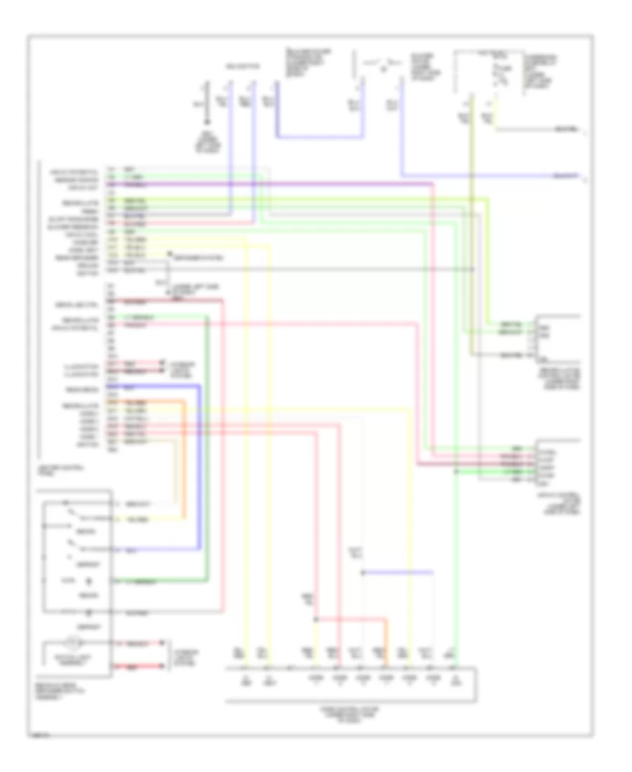
Heater Wiring Diagram, Hatchback (2 of 2) for Honda Civic 2005
 https://portal-diagnostov.com/license.html
Automotive Electricians Portal FZCO
Automotive Electricians Portal FZCO
https://portal-diagnostov.com/license.html
https://portal-diagnostov.com/license.html
Automotive Electricians Portal FZCO
Automotive Electricians Portal FZCOList of elements for Heater Wiring Diagram, Hatchback (2 of 2) for Honda Civic 2005:
- (behind left side of front bumper) g301
- Blower motor relay
- D13
- Ecm (behind glove box)
- Fan control (fanc)
- Fuse 20a
- Fuse 40a
- Hot at all times
- Radiator fan motor (behind radiator)
- Radiator fan relay
- Radiator fan switch (under radiator) (closed above: 199 degrees fahenheit 93 degrees celsius)
- Red
- Underhood fuse/relay box (left side of engine compartment)
Manual A/C Wiring Diagram, Except Hatchback & Hybrid (1 of 2) for Honda Civic 2005
 https://portal-diagnostov.com/license.html
Automotive Electricians Portal FZCO
Automotive Electricians Portal FZCO
https://portal-diagnostov.com/license.html
https://portal-diagnostov.com/license.html
Automotive Electricians Portal FZCO
Automotive Electricians Portal FZCOList of elements for Manual A/C Wiring Diagram, Except Hatchback & Hybrid (1 of 2) for Honda Civic 2005:
- A/c
- A10
- A11
- A12
- A13
- A14
- Air delivery
- Air mix control motor (on left side of hvac assembly)
- Amd-p
- B10
- B11
- B12
- B13
- B14
- B15
- B16
- B17
- B18
- B19
- B20
- B21
- B22
- Blower controls
- Blower motor (under right side of dash)
- Blower power transistor (under right side of dash, near blower motor)
- Compressor ctrls
- Defogger
- Defogger system
- Defrost
- Evaporator temperature sensor (under middle of dash)
- Frs
- Fuse 10a
- G502 (under center of dash)
- Ground
- Heater control panel
- Hot in on
- Ig2
- Ignition
- Illumination
- Interior lights system
- M-cool
- M-def
- M-hot
- M-vent
- Mode control motor (behind glove box)
- Mode-1
- Mode-2
- Mode-3
- Mode-4
- Rec
- Recirc
- Recirc-a/c defogger switch assembly
- Recirculation control motor (behind glove box)
- Red
- S-com
- S5v
- Solid state
- Switch assembly light
- Under-dash fuse/relay box (under left side of dash)
Manual A/C Wiring Diagram, Except Hatchback & Hybrid (2 of 2) for Honda Civic 2005
 https://portal-diagnostov.com/license.html
Automotive Electricians Portal FZCO
Automotive Electricians Portal FZCO
https://portal-diagnostov.com/license.html
https://portal-diagnostov.com/license.html
Automotive Electricians Portal FZCO
Automotive Electricians Portal FZCOList of elements for Manual A/C Wiring Diagram, Except Hatchback & Hybrid (2 of 2) for Honda Civic 2005:
- (not used)
- A/c clutch relay
- A/c compressor (behind left side of a/c condenser fan motor)
- A/c compressor clutch
- A/c compressor clutch relay
- A/c condenser fan motor (behind a/c condenser fan motor)
- A/c condenser fan relay
- A/c press switch
- A/c pressure switch (left side of engine compt)
- A10
- Accessory a/c
- Blower motor relay
- Communi- cation (sefmj)
- D10
- D13
- E10
- E18
- E24
- Ecm/pcm (behind glove box)
- Ect sensor (rear of engine)
- Except gx
- Factory a/c
- Fan control
- Fuse 20a
- Fuse 40a
- G101 (middle of engine)
- G13 (at left front side of engine compt)
- G201 (behind right side of front bumper)
- High
- Hot at all times
- Junction connector c102 (behind glove compartment) (except gx: terminals 5-7) (gx: terminals 14-16)
- Junction connector c103 (on cylinder head cover)
- Low
- Multiplex control unit
- Optional connector (for a/c) (with accessory a/c installed)
- Radiator fan motor (middle of engine compt)
- Radiator fan relay
- Radiator fan switch (middle of engine) (closed above: 199 degrees fahrenheit, 93 degrees celsius)
- Red
- Sedan
- Sens gnd
- Sens input
- Thermal protector
- Under-dash fuse/relay box (under left side of dash)
- Under-hood fuse/relay box (right side of engine compt)
Manual A/C Wiring Diagram, Hatchback (1 of 2) for Honda Civic 2005
 https://portal-diagnostov.com/license.html
Automotive Electricians Portal FZCO
Automotive Electricians Portal FZCO
https://portal-diagnostov.com/license.html
https://portal-diagnostov.com/license.html
Automotive Electricians Portal FZCO
Automotive Electricians Portal FZCOList of elements for Manual A/C Wiring Diagram, Hatchback (1 of 2) for Honda Civic 2005:
- (under left side of dash) g501
- A/c
- A/c led ctrl
- A/c on input
- A/c press switch
- A10
- A11
- A12
- A13
- A14
- Air mix control motor (under left side of dash)
- Air mix cool
- Air mix hot
- Air mix potential
- Amd-p
- B10
- B11
- B12
- B13
- B14
- B15
- B16
- B17
- B18
- B19
- B20
- B21
- B22
- Blower feedback
- Blower motor (under right side of dash)
- Blower power transistor (under right side of dash)
- Blwr trans base
- Defog led ctrl
- Defogger system
- Defrost
- Evap temp sensor
- Evaporator temperature sensor (under left side of dash)
- Fresh
- Frs
- Fuse 10a
- G501 (under left side of dash)
- Ground
- Heater control panel
- Hot in on
- Ig2
- Ignition
- Illumination
- Interior lights system
- M- def
- M- vent
- M-cool
- M-hot
- Mode -1
- Mode -2
- Mode -3
- Mode -4
- Mode 1
- Mode 2
- Mode 3
- Mode 4
- Mode control motor (under right side of dash)
- Mode def
- Mode vent
- Rear defog
- Rear defogger
- Rec
- Recir-a/c rear defogger switch assembly
- Recirc
- Recirc led ctrl
- Recirc request
- Recirculate
- Recirculation control motor (under right side of dash)
- Red
- S- com
- S-com
- S5v
- Sensor common
- Solid state
- Switch assembly light
- Underdash fuse/relay box (under left side of dash)
Manual A/C Wiring Diagram, Hatchback (2 of 2) for Honda Civic 2005
 https://portal-diagnostov.com/license.html
Automotive Electricians Portal FZCO
Automotive Electricians Portal FZCO
https://portal-diagnostov.com/license.html
https://portal-diagnostov.com/license.html
Automotive Electricians Portal FZCO
Automotive Electricians Portal FZCOList of elements for Manual A/C Wiring Diagram, Hatchback (2 of 2) for Honda Civic 2005:
- (acc)
- (behind left side of front bumper) g301
- (ecu) bus
- (fanc)
- (sefmj)
- A/c compressor
- A/c compressor clutch
- A/c compressor clutch relay
- A/c condenser fan motor (right front of engine compartment)
- A/c condenser fan relay
- A/c pressure switch (acs)
- A/c pressure switch (left front of engine compartment)
- Blower motor relay
- Communication e24
- D10
- D13
- E10
- Ecm (behind glove box)
- Fan control b6
- Fuse 20a
- Fuse 40a
- High
- Hot at all times
- Low
- Multiplex control unit
- Nca
- Radiator fan motor (left front of engine compartment)
- Radiator fan relay
- Radiator fan switch (under radiator) (closed above: 199 degrees fahrenheit, 93 degrees celsius)
- Red
- Relay ctrl e18
- Thermal protector (above 252 kpa (122 psi)
- Underdash fuse/relay box (under left side of dash)
- Underhood fuse/relay box (left side of engine compartment)

 Čeština
 Dansk
Dansk Deutsch
 Ελληνικά
 English
 English
 Español
 Suomi
Suomi Français
 Français
 עברית
עברית Hrvatski
 Magyar
 Italiano
 日本語
日本語 Nederlands
 Polski
 Português
 Português
 Română
 Русский
 Slovenčina
 Slovenščina
 Svenska
 Türkçe
 中文 (中国)
