ENGINE PERFORMANCE
3.5L
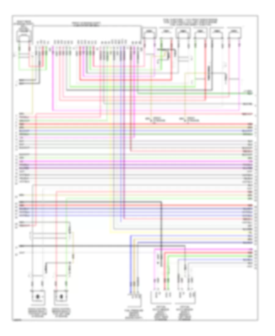
3.5L, Engine Performance Wiring Diagram (1 of 8) for Lexus IS 350 2008


List of elements for 3.5L, Engine Performance Wiring Diagram (1 of 8) for Lexus IS 350 2008:
- (behind left center of front bumper fascia) ambient temperature sensor
- (left side of engine compt) engine room j/b 2
- +b1
- Accelerator position sensor (under left side of dash)
- Accr
- Acmg
- Air conditioning system
- Batt
- C/opn relay
- Canh
- Canl
- Cchg
- Ccs
- Computer data lines system
- Cooling fans system
- Cruise control system
- Ctsw
- Efi 2 relay
- Efi fuse 25a
- Efi main relay
- Efii
- Efio
- Engine control module (on left front of engine compt, in protective case)
- Epa
- Epa2
- Eppm
- Etam
- F/pmp fuse 25a
- Fan
- Fan2
- Fpr
- Heated oxygen sensor (bank 1 sensor 2) (on right side exhaust system)
- Heated oxygen sensor (bank 2 sensor 2) (on left side exhaust system)
- Hot at all times
- Ht1b
- Ht2b
- Id code box (behind center of dash)
- Igsw
- Imi
- Imo
- Irel
- Ksw
- Lgnd
- Mpmp
- Mrel
- Nca
- O1b-
- O2b-
- Ox1b
- Ox2b
- Pnk
- Power source control ecu (behind right side of dash)
- Ppmp
- Red
- Sftd
- Sftu
- Sksw
- Spd
- St1-
- Sta
- Starting/charging system
- Stp
- Stsw
- Tach
- Tam
- Vcp2
- Vcpa
- Vcpp
- Vpa
- Vpa2
- Vpmp
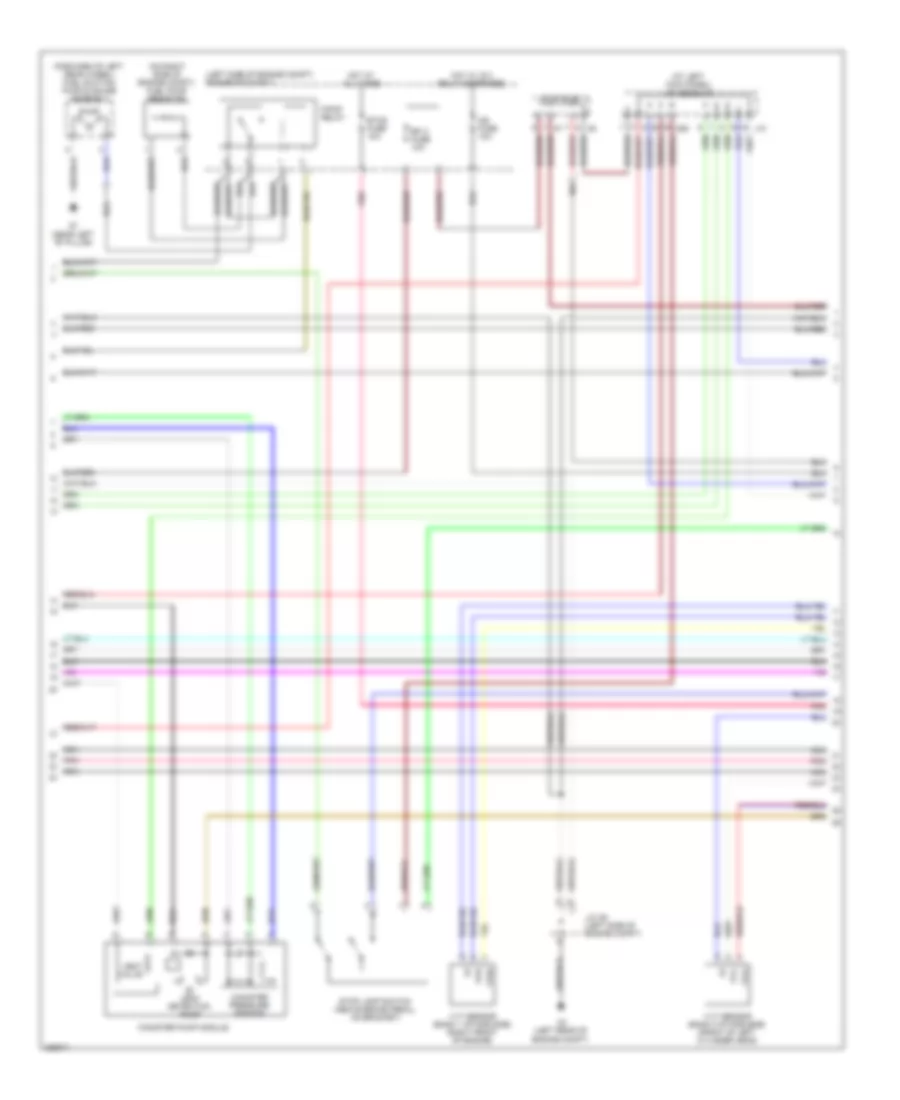
3.5L, Engine Performance Wiring Diagram (2 of 8) for Lexus IS 350 2008
List of elements for 3.5L, Engine Performance Wiring Diagram (2 of 8) for Lexus IS 350 2008:
- (at left kick panel) j/c a29 & j10
- (forward of left rear wheel) fuel suction pump & gauge assembly
- (left side of engine compt) engine room r/b 2
- (on right side of engine compt) fuel pump resistor
- A2 (left rear of engine compt)
- A29
- Canister pressure sensor
- Canister pump module
- Efi 2 fuse 10a
- Etcs fuse 10a
- F/pmp relay
- Hot at all times
- Hot w/ ig 2 relay energized
- Ig2 fuse 10a
- J/c a7 & a8
- J/c a9 (left side of engine compt)
- J10
- Leak detection pump
- Nca
- Pnk
- Pump
- Q1 (near left "b" pillar)
- Stop lamp switch (above brake pedal, on bracket)
- Vent valve
- Vvl+
- Vvl-
- Vvr+
- Vvr-
- Vvt sensor (bank 1 intake side) (right front of engine)
- Vvt sensor (bank 2 intake side) (front of left cylinder head)
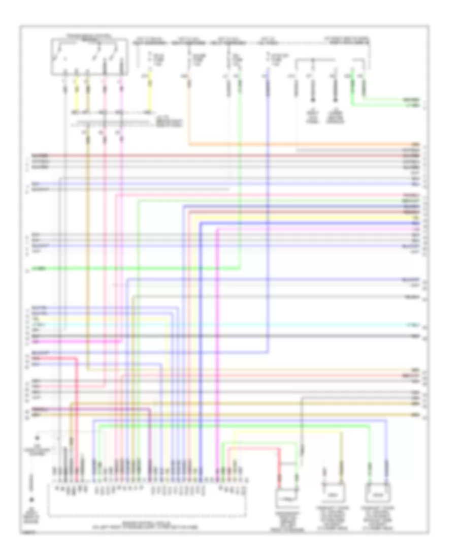
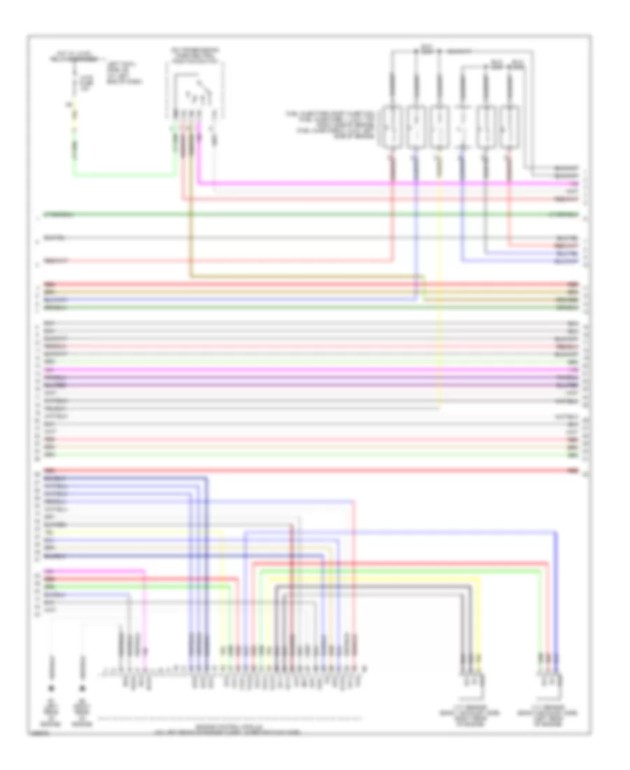
3.5L, Engine Performance Wiring Diagram (3 of 8) for Lexus IS 350 2008
List of elements for 3.5L, Engine Performance Wiring Diagram (3 of 8) for Lexus IS 350 2008:
- (at right end of dash) right cowl side j/b
- +bm
- A10
- A24
- A25
- Air conditioning system
- Camshaft timing oil control valve (right exhaust side) (on right cylinder head)
- Camshaft timing oil control valve (right intake side) (on right cylinder head)
- Crankshaft position sensor (on left front of engine)
- D13
- E03
- E2 (right rear of engine)
- Engine control module (on left front of engine compt, in protective case)
- Eta
- Gauge fuse 7.5a
- Ge01
- Hot at all times
- Hot w/ ig 2 relay energized
- Hot w/ rh-ig1 relay energized
- Ign fuse 10a
- J/c j70 (behind right side of dash)
- J2 (under center console)
- J4 (right kick panel)
- Lck1
- Me01
- Nca
- Ne+
- Ne-
- Oc1+
- Oc1-
- Oe1+
- Oe1-
- Pnk
- Prg
- Red
- Rh-ig fuse 7.5a
- Sftd
- Sftu
- Stop sw fuse 7.5a
- Transmission control switch
- Vcta
- Vcv1
- Vcv2
- Vta1
- Vta2
- Vv1+
- Vv1-
- Vv2+
- Vv2-
3.5L, Engine Performance Wiring Diagram (4 of 8) for Lexus IS 350 2008
List of elements for 3.5L, Engine Performance Wiring Diagram (4 of 8) for Lexus IS 350 2008:
- (behind left side of dash) j/c j27
- A10
- Body ecu (at right & left ends of dash)
- Combination meter
- Computer data lines system
- Cruise control system
- Dome fuse 10a
- E1 (left rear of engine)
- Ect pwr ind
- Ect snow ind
- Efi
- Electronically controlled transmission pattern select switch
- Engine oil level sensor (near bottom of engine)
- Engine room r/b 1 (right rear of engine compt)
- Hot at all times
- Ig+
- Ig2 or dome +b
- Indicator malfunction
- Input circuit
- Interior lights system
- J/c a10 & e1 (j/c e1: left side of engine compt)
- J/c j70 (behind right side of dash)
- J1 (left kick panel)
- J21
- J34
- J35
- J75
- Lamp
- Left cowl side j/b (at left end of dash)
- Master ind
- Micro computer
- Micro computer (sub)
- Mpx+
- Mpx-
- Mpx-b fuse 10a
- Mpx1
- Mpx2
- Multi information display
- Nca
- Pnk
- Pwr
- Red
- Right cowl side j/b (at right end of dash)
- Snow
- Speedometer
- Tachometer
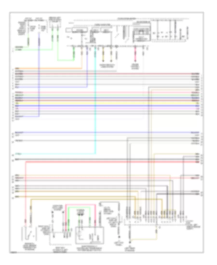
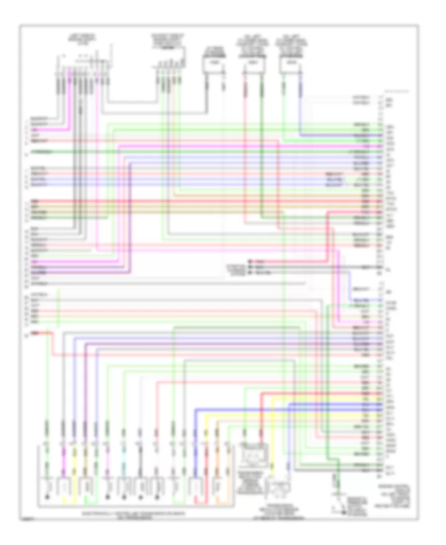
3.5L, Engine Performance Wiring Diagram (5 of 8) for Lexus IS 350 2008
List of elements for 3.5L, Engine Performance Wiring Diagram (5 of 8) for Lexus IS 350 2008:
- (at rear of engine) engine coolant temperature sensor
- A/f fuse 15a
- A/f relay
- E2 (right rear of engine)
- Engine room j/b 2 & engine room r/b 2 (left side of engine compt)
- Gnd
- Hot at all times
- Igf1
- Igf2
- Ignition coil 1 (on top of engine)
- Ignition coil 2 (on top of engine)
- Ignition coil 3 (on top of engine)
- Ignition coil 4 (on top of engine)
- Ignition coil 5 (on top of engine)
- Ignition coil 6 (on top of engine)
- Igt1
- Igt2
- Igt3
- Igt4
- Igt5
- Igt6
- Inj fuse 20a
- Inj relay
- Nca
- Noise filter (ignition left) (on left side of engine)
- Noise filter (ignition right) (on right side of engine)
- Red
- Throttle body assembly
3.5L, Engine Performance Wiring Diagram (6 of 8) for Lexus IS 350 2008
List of elements for 3.5L, Engine Performance Wiring Diagram (6 of 8) for Lexus IS 350 2008:
- (front of engine compt) injector driver (edu)
- (front of engine) h1
- (front of engine) i1
- (fuel injectors 1, 3 & 5: (right side of engine) (fuel injectors 2, 4 & 6: (left side of engine) fuel injectors (direct injection)
- (right rear of engine compt) spill control valve
- +b2
- A1a+
- A1a-
- A2a+
- A2a-
- Air fuel ratio sensor (bank 1 sensor 1) (right rear of engine)
- Air fuel ratio sensor (bank 2 sensor 1) (left rear of engine)
- E26
- E27
- Fp+
- Fp-
- Fpd
- Fpf1
- Fuel pressure sensor (rear of engine compt)
- Ha1a
- Ha2a
- Ij1+
- Ij1-
- Ij2+
- Ij2-
- Ij3+
- Ij3-
- Ij4+
- Ij4-
- Ij5+
- Ij5-
- Ij6+
- Ij6-
- Ijf2
- Ijf3
- Injf
- Knock control sensor (bank 1) (top right side of engine)
- Knock control sensor (bank 2) (top left side of engine)
- Nca
- Pnk
- Red
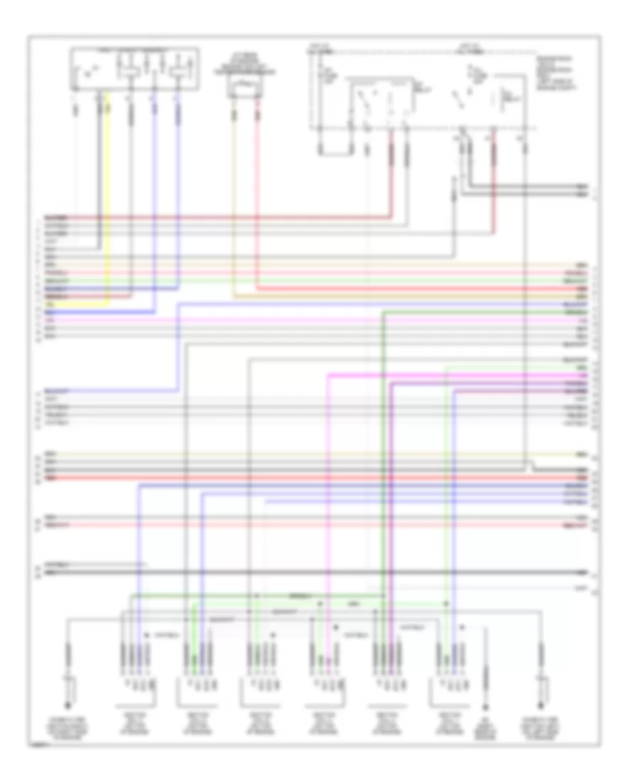
3.5L, Engine Performance Wiring Diagram (7 of 8) for Lexus IS 350 2008
List of elements for 3.5L, Engine Performance Wiring Diagram (7 of 8) for Lexus IS 350 2008:
- (on transmission) park/neutral position switch
- A1a+
- A1a-
- A2a+
- A2a-
- E1 (left rear of engine)
- E2 (right rear of engine)
- Engine control module (on left front of engine compt, in protective case)
- Eo4
- Eo5
- Epr
- Ev1+
- Ev1-
- Ev2+
- Ev2-
- Ex+
- Ex-
- Fpd
- Fpf1
- Fuel injectors (port injection) (fuel injectors 1, 3 & 5: top right side of engine) (fuel injectors 2, 4 & 6: left side of engine)
- Ha1a
- Ha2a
- Hot w/ lh-ig1 relay energized
- Igt2
- Igt5
- Igt6
- Ijf2
- Ijf3
- Injf
- Left cowl side j/b (at left end of dash)
- Lh-ig fuse 10a
- Red
- Vc2
- Vce1
- Vce2
- Vcpr
- Vvt sensor (bank 1 exhaust side) (right rear of engine)
- Vvt sensor (bank 2 exhaust side) (left rear of engine)
3.5L, Engine Performance Wiring Diagram (8 of 8) for Lexus IS 350 2008
List of elements for 3.5L, Engine Performance Wiring Diagram (8 of 8) for Lexus IS 350 2008:
- (at rear of engine) vsv (purge)
- (left side of engine compt) j/c e2
- (on left cylinder head) camshaft timing oil control valve (left exhaust side)
- (on left cylinder head) camshaft timing oil control valve (left intake side)
- (on right side of engine compt) mass air flow meter
- Alt
- E01
- E02
- E2g
- Ekn2
- Eknk
- Electronically controlled transmission solenoid (on transmission)
- Engine control module (on left front of engine compt, in protective case)
- Engine oil pressure switch (on front of engine)
- Eoil
- Etha
- Ethw
- Igf1
- Igf2
- Igt1
- Igt3
- Igt4
- Knk1
- Knk2
- Mol
- Mops
- Nt+
- Nt-
- Oc2+
- Oc2-
- Oe2+
- Oe2-
- Oil
- Pnk
- Red
- Sl1+
- Sl1-
- Sl2+
- Sl2-
- Slt+
- Slt-
- Slu+
- Slu-
- Sp2+
- Sp2-
- Star
- Starting/ charging system
- Tha
- Thw
- Transmission revolution sensor (counter gear) (at rear of transmission)
- Transmission revolution sensor (turbine) (at front of transmission)

 Čeština
 Dansk
Dansk Deutsch
 Ελληνικά
 English
 English
 Español
 Suomi
Suomi Français
 Français
 עברית
עברית Hrvatski
 Magyar
 Italiano
 日本語
日本語 Nederlands
 Polski
 Português
 Português
 Română
 Русский
 Slovenčina
 Slovenščina
 Svenska
 Türkçe
 中文 (中国)