Čeština
 Dansk
Dansk Deutsch
 Ελληνικά
 English
 English
 Español
 Suomi
Suomi Français
 Français
 עברית
עברית Hrvatski
 Magyar
 Italiano
 日本語
日本語 Nederlands
 Polski
 Português
 Português
 Română
 Русский
 Slovenčina
 Slovenščina
 Svenska
 Türkçe
 中文 (中国)

AIR CONDITIONING
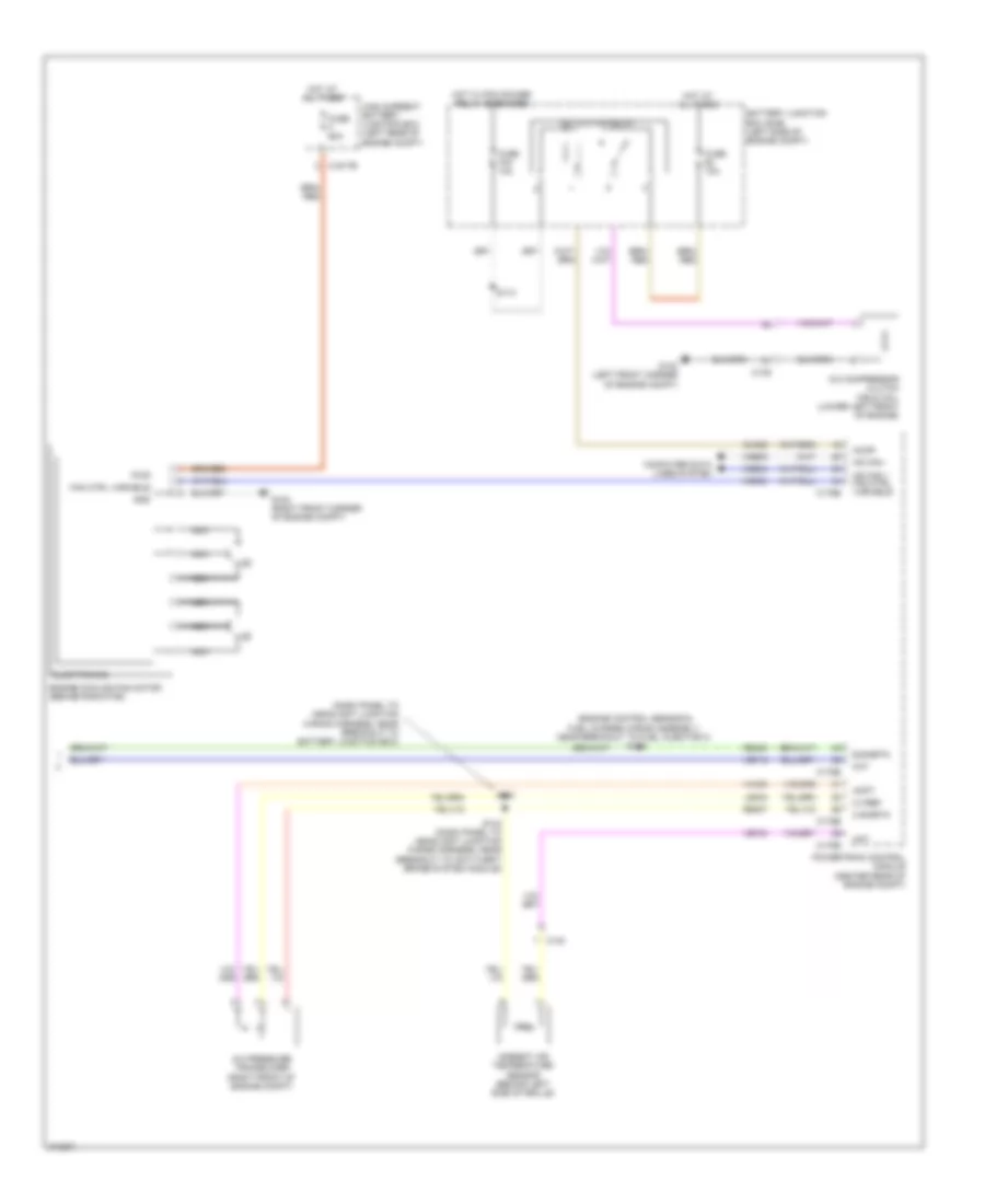
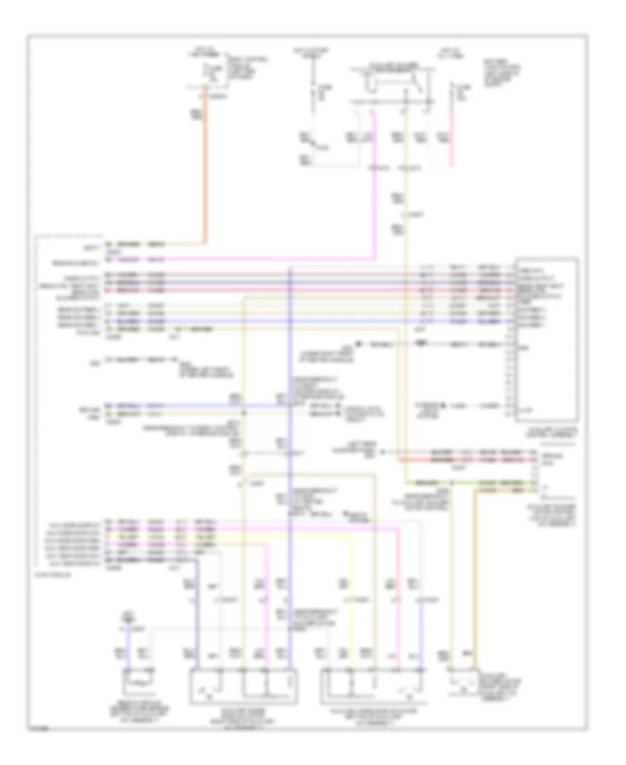
Automatic A/C Wiring Diagram (1 of 3) for Ford Explorer XLT 2011
List of elements for Automatic A/C Wiring Diagram (1 of 3) for Ford Explorer XLT 2011:
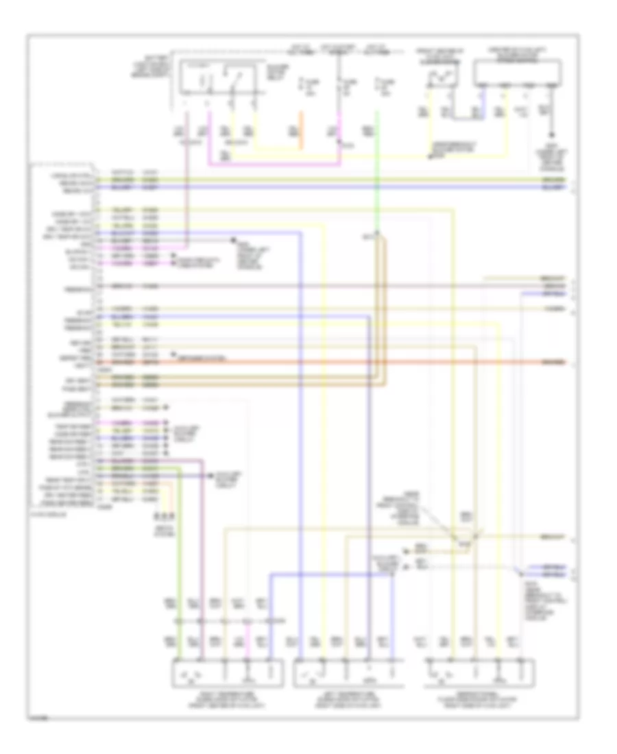

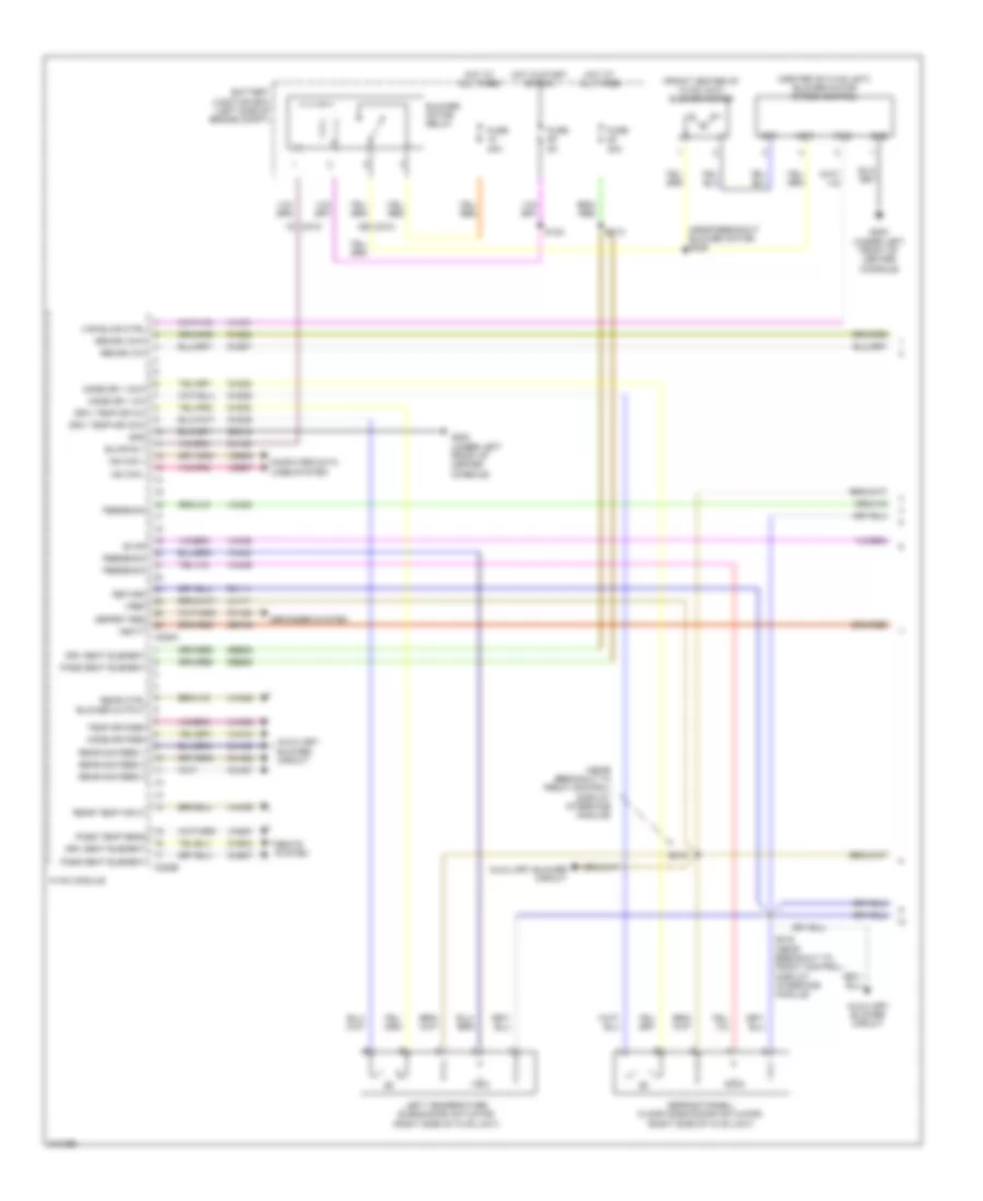
Automatic A/C Wiring Diagram (2 of 3) for Ford Explorer XLT 2011
List of elements for Automatic A/C Wiring Diagram (2 of 3) for Ford Explorer XLT 2011:
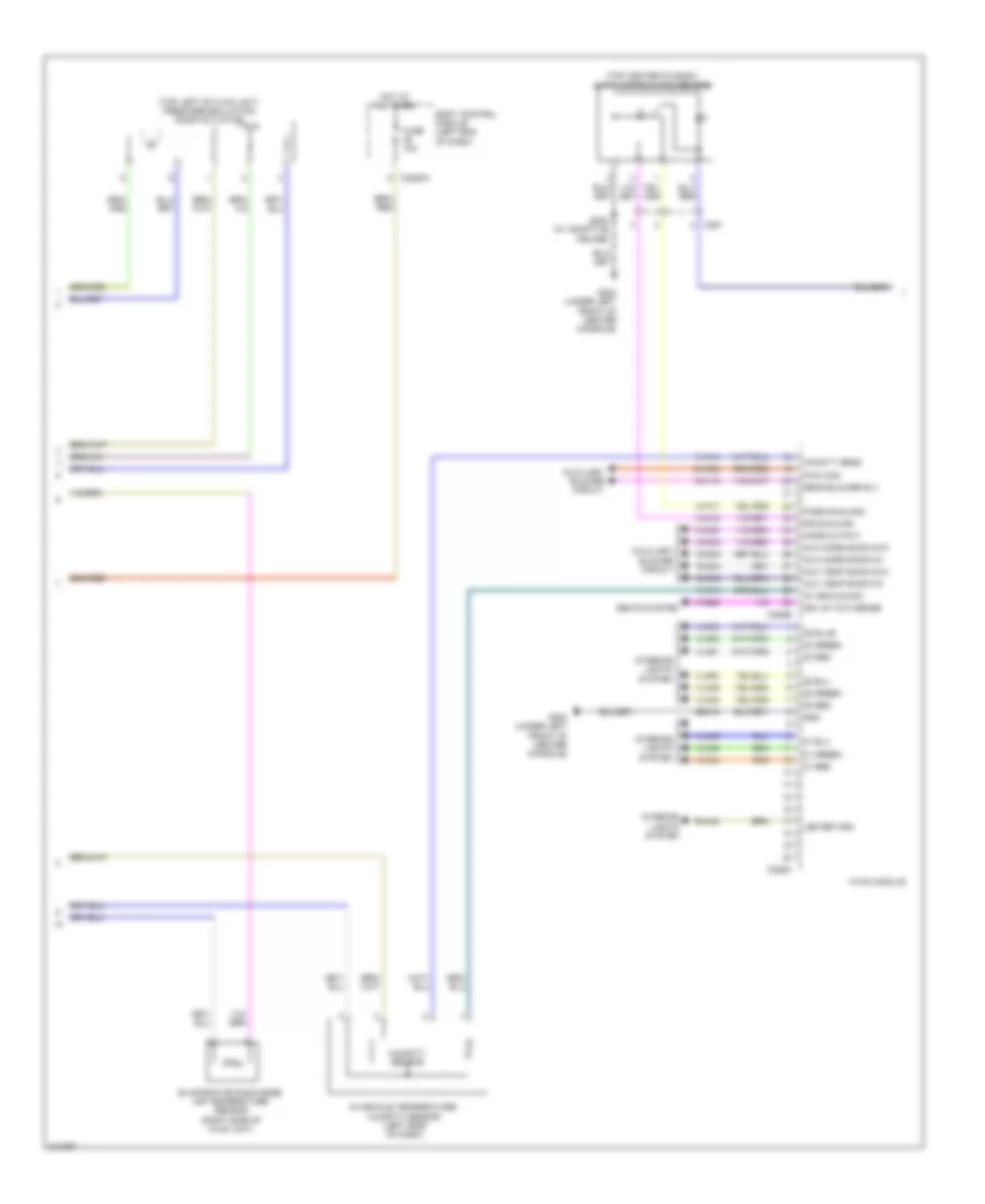
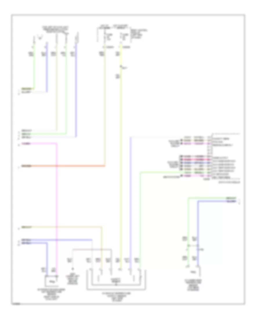
Automatic A/C Wiring Diagram (3 of 3) for Ford Explorer XLT 2011
List of elements for Automatic A/C Wiring Diagram (3 of 3) for Ford Explorer XLT 2011:
Auxiliary Blower Wiring Diagram for Ford Explorer XLT 2011
List of elements for Auxiliary Blower Wiring Diagram for Ford Explorer XLT 2011:
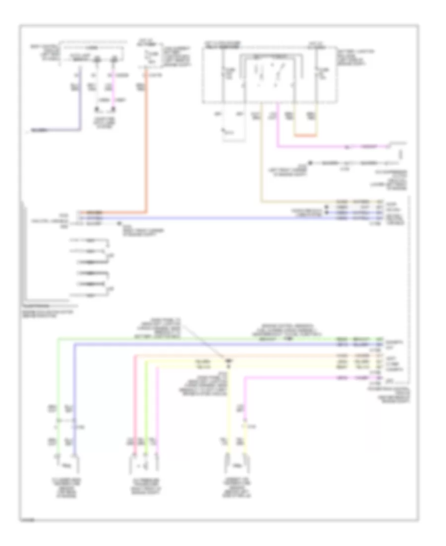
Manual A/C Wiring Diagram (1 of 3) for Ford Explorer XLT 2011
List of elements for Manual A/C Wiring Diagram (1 of 3) for Ford Explorer XLT 2011:
Manual A/C Wiring Diagram (2 of 3) for Ford Explorer XLT 2011
List of elements for Manual A/C Wiring Diagram (2 of 3) for Ford Explorer XLT 2011:
Manual A/C Wiring Diagram (3 of 3) for Ford Explorer XLT 2011
List of elements for Manual A/C Wiring Diagram (3 of 3) for Ford Explorer XLT 2011: