ANTI-LOCK BRAKES
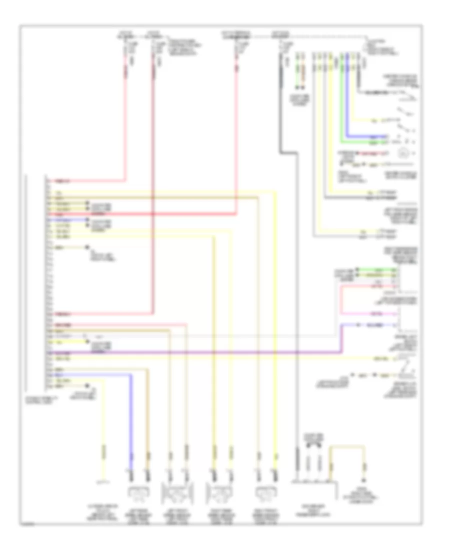
Anti-lock Brakes Wiring Diagram for MINI Cooper Works 2009
 https://portal-diagnostov.com/license.html
Automotive Electricians Portal FZCO
Automotive Electricians Portal FZCO
https://portal-diagnostov.com/license.html
https://portal-diagnostov.com/license.html
Automotive Electricians Portal FZCO
Automotive Electricians Portal FZCO
List of elements for Anti-lock Brakes Wiring Diagram for MINI Cooper Works 2009:
- (center console) parking brake warning switch
- Brake fluid level switch (left rear side of engine compt)
- Brake light switch (left side of left footwell)
- Car access system (left top side of dash)
- Center console switch cluster
- Computer data lines system
- Dsc sensor (right passenger floor)
- Dynamic stability control (dsc)
- Front power distribution box (left side of engine compt)
- Fuse f06 25a
- Fuse f18 5a
- Fuse f35 5a
- Fuse fl6 40a
- Hot at all times
- Hot in on or start
- Hot w/ terminal 30g energized
- Interior lights system
- Junction box (right side of right footwell)
- Left front brake pad wear sensor (front of left front wheel)
- Left front speed sensor (left front wheel hub)
- Left rear speed sensor (left rear wheel hub)
- Nca
- Outside mirror fold in (behind left rear trim panel)
- Red
- Right front speed sensor (right front wheel hub)
- Right rear brake pad wear sensor (behind right rear wheel)
- Right rear speed sensor (right rear wheel hub)
- X10318
- X11002
- X1108
- X14272
- X175 (left front side of engine compt)
- X2042 (left side of left footwell)
- X2846 (right side of right footwell, under door)
- X4 (top of left front wheel)
- X4010
- X4013
 Čeština
 Dansk
Dansk Deutsch
 Ελληνικά
 English
 English
 Español
 Suomi
Suomi Français
 Français
 עברית
עברית Hrvatski
 Magyar
 Italiano
 日本語
日本語 Nederlands
 Polski
 Português
 Português
 Română
 Русский
 Slovenčina
 Slovenščina
 Svenska
 Türkçe
 中文 (中国)
 한국어
한국어
