Čeština
 Dansk
Dansk Deutsch
 Ελληνικά
 English
 English
 Español
 Suomi
Suomi Français
 Français
 עברית
עברית Hrvatski
 Magyar
 Italiano
 日本語
日本語 Nederlands
 Polski
 Português
 Português
 Română
 Русский
 Slovenčina
 Slovenščina
 Svenska
 Türkçe
 中文 (中国)
СИСТЕМА ПЕРЕДАЧИ ДАННЫХ
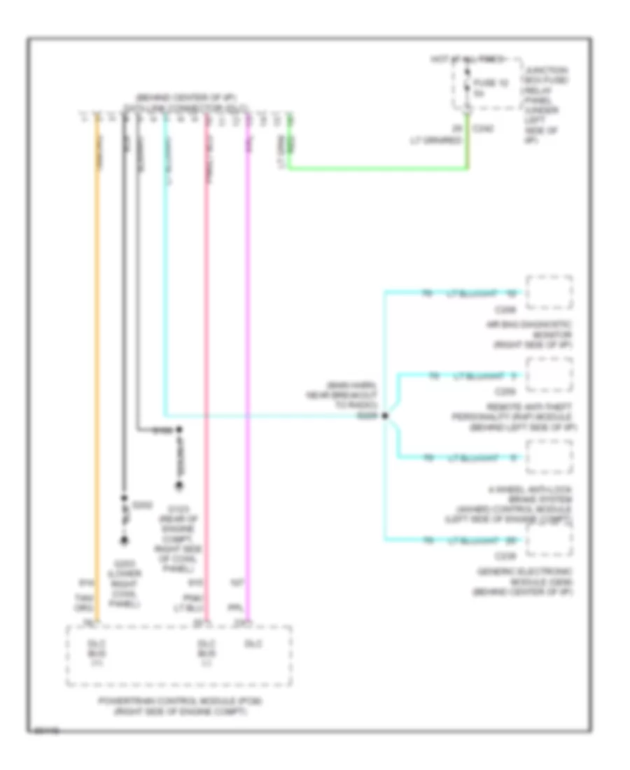
Электросхема компьютерной линии передачи данных CAN для Ford Pickup F150 1997
Электросхема компьютерной линии передачи данных CAN для Ford Pickup F150 1997 - Список элементов:
The new database is currently being populated with wiring diagrams up to 2024.
 한국어
한국어

Электросхема компьютерной линии передачи данных CAN для Ford Pickup F150 1997
Электросхема компьютерной линии передачи данных CAN для Ford Pickup F150 1997 - Список элементов: