ENGINE PERFORMANCE
4.0L
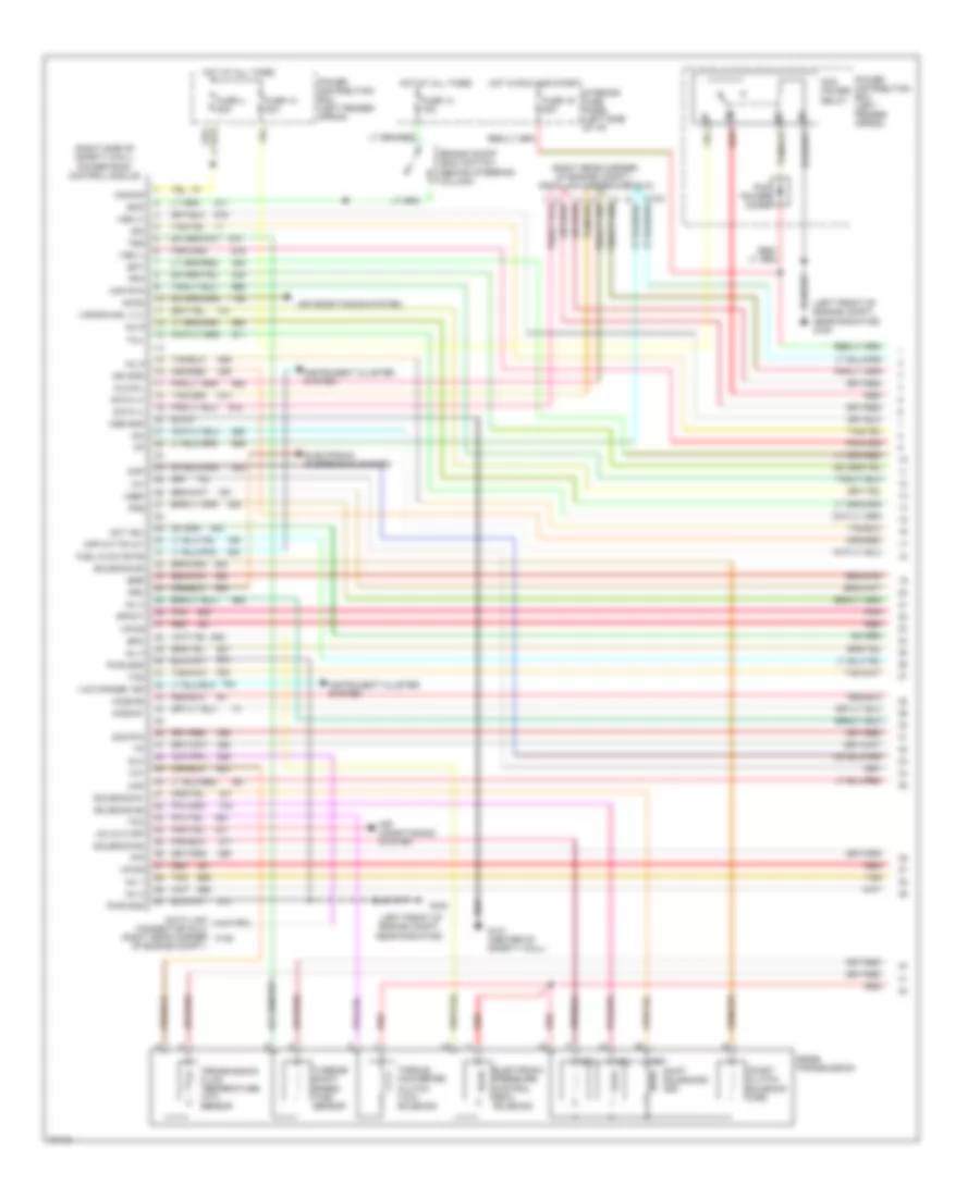
4.0L, Engine Performance Wiring Diagrams (1 of 3) for Ford Explorer 1995
 https://portal-diagnostov.com/license.html
Automotive Electricians Portal FZCO
Automotive Electricians Portal FZCO
https://portal-diagnostov.com/license.html
https://portal-diagnostov.com/license.html
Automotive Electricians Portal FZCO
Automotive Electricians Portal FZCO
List of elements for 4.0L, Engine Performance Wiring Diagrams (1 of 3) for Ford Explorer 1995:
- "low range" ind
- (left front of engine compt., near radiator)
- (left front of engine compt., near radiator) g100
- (right rear corner of engine compt.) data link connector (dlc)
- (right side of safety wall) powertrain control module
- 4r55e transmission
- A/c cut-off
- Accs
- Air conditioning system
- Arc
- Boo
- Brake on/off (boo) switch (behind steering column)
- Cmp
- Coast clutch solenoid (css)
- Cpp m/t-tr a/t
- Cse gnd
- Data (+)
- Data (-)
- Data link connector (dlc) (right rear corner c105
- Dlc
- Dlc/mil
- Ect
- Egr
- Electronic pressure control (epc) solenoid
- Electronic suspension system
- Epc
- Fpm
- Fuel flow rate
- Fuse 13 15a
- Fuse 13 30a
- Fuse 19 25a
- Fuse 4 20a
- G100
- G121 (center of safety wall)
- Ho2s #1
- Ho2s #2
- Hot at all times
- Hot in run and start
- Iac
- Iat
- Idm
- Ign gnd
- Inj 1
- Inj 2
- Inj 3
- Inj 4
- Inj 5
- Inj 6
- Instrument cluster system
- Interior fuse panel (left side of i/p)
- Kapwr
- Maf
- Maf rtn
- Oct adj
- Of engine compt.)
- Pcm power diode
- Pcm power relay
- Pfe
- Pip
- Pnk
- Power distribution box (left fender apron)
- Pwr gnd
- Red
- Shift solenoids (ss)
- Sig rtn
- Solenoid #1
- Solenoid #2
- Solenoid #3
- Solenoid #4
- Spout
- Ss1
- Ss2
- Ss3
- Tan
- Tcc
- Tcil
- Tcs
- Tft
- Torque converter clutch (tcc) solenoid
- Transmission fluid temperature (tft) sensor
- Tss
- Turbine shaft speed (tss) sensor
- Vapor man. vlv
- Vpwr
- Vref
- Vss (+)
- Vss (-)
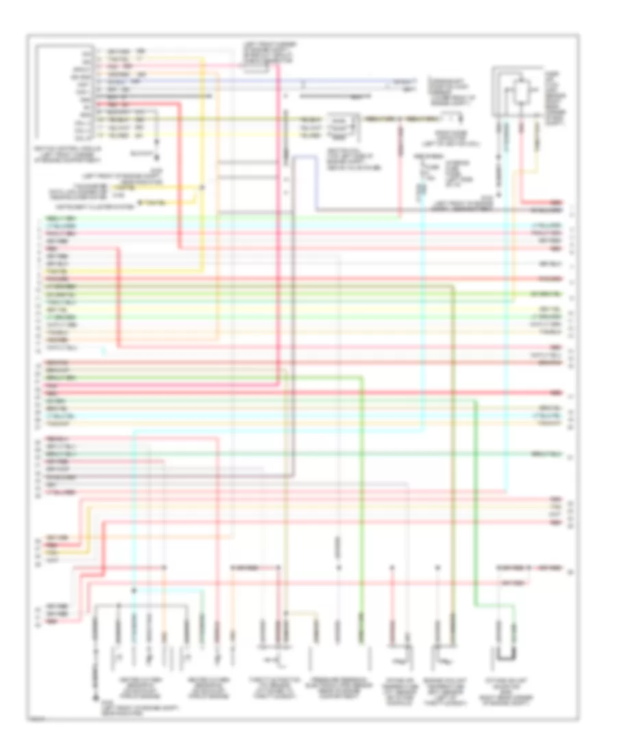
4.0L, Engine Performance Wiring Diagrams (2 of 3) for Ford Explorer 1995
 https://portal-diagnostov.com/license.html
Automotive Electricians Portal FZCO
Automotive Electricians Portal FZCO
https://portal-diagnostov.com/license.html
https://portal-diagnostov.com/license.html
Automotive Electricians Portal FZCO
Automotive Electricians Portal FZCOList of elements for 4.0L, Engine Performance Wiring Diagrams (2 of 3) for Ford Explorer 1995:
- (left front corner of engine compt.) spark out (spout) check connector
- C106
- Ckp +
- Ckp -
- Coil a
- Coil b
- Coil c
- Crankshaft position (ckp) sensor (lower front of engine compt.)
- Engine coolant temperature (ect) sensor (left of throttle body)
- Fuse 15a
- G100 (left front of engine compt., near battery)
- G100 (left front of engine compt., near radiator)
- Gnd
- Heated oxygen sensor #1 (on exhaust pipe of engine)
- Heated oxygen sensor #2 (on exhaust pipe of engine)
- Hot in run
- Idm
- Ign gnd
- Ignition coil (top left side of engine compt., above valve cover)
- Ignition control module (left front corner of engine compartment)
- Instrument cluster system
- Intake air temperature (iat) sensor (on intake manifold)
- Interior fuse panel (left side of i/p)
- Mass air flow (maf) sensor (right rear corner of eng. compt.)
- Octane adjust (shorting bar) (right rear corner of engine compt.)
- Pip
- Pnk
- Pressure feedback electronic (pfe) sensor (rear of engine compartment)
- Radio noise capacitor (left of ignition coil)
- Red
- Spout
- Tachometer data link connector (near blower motor)
- Tan
- Throttle position (tp) sensor (attached to throttle body)
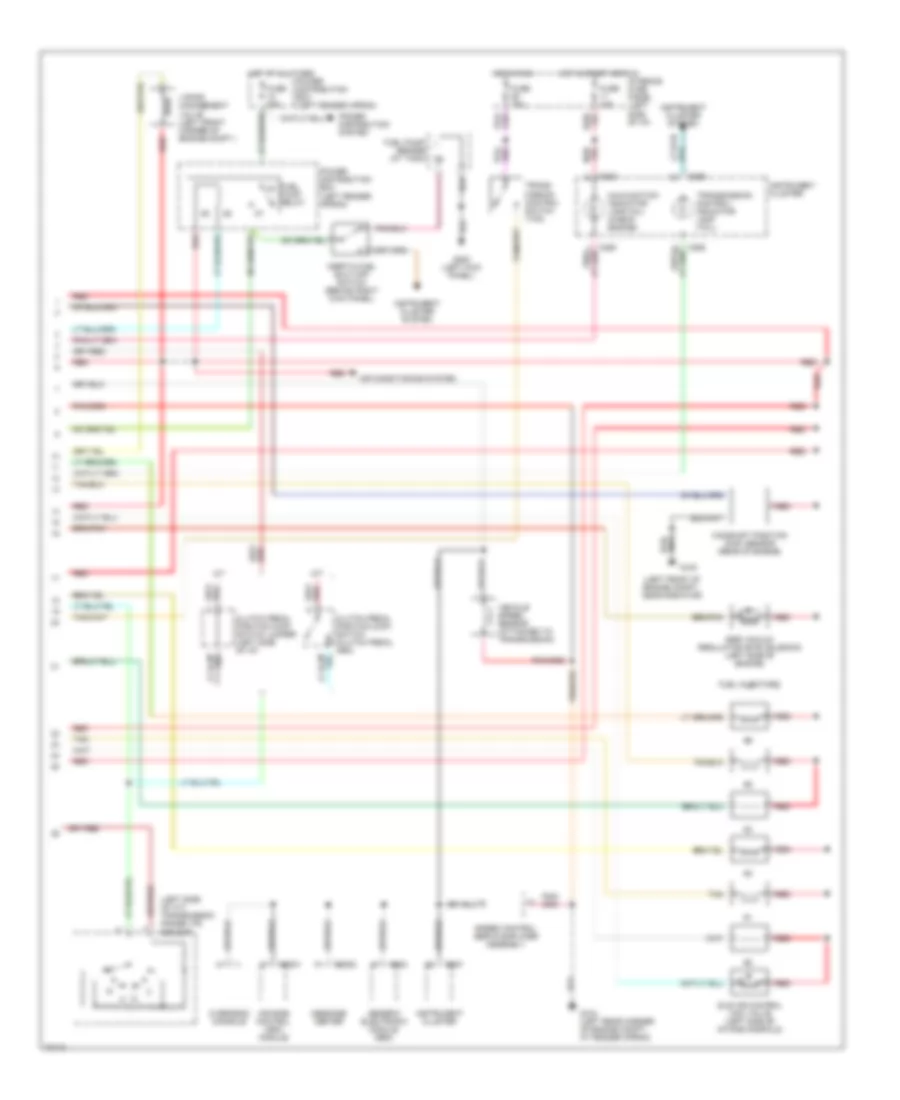
4.0L, Engine Performance Wiring Diagrams (3 of 3) for Ford Explorer 1995
 https://portal-diagnostov.com/license.html
Automotive Electricians Portal FZCO
Automotive Electricians Portal FZCO
https://portal-diagnostov.com/license.html
https://portal-diagnostov.com/license.html
Automotive Electricians Portal FZCO
Automotive Electricians Portal FZCOList of elements for 4.0L, Engine Performance Wiring Diagrams (3 of 3) for Ford Explorer 1995:
- "transmission control" indicator lamp (tcil)
- (left front of engine compt., near radiator)
- (left side of a/t) transmission range (tr) sensor
- A/t
- Air conditioning system
- Air ride control (arc) module
- C2001
- C2008
- C283
- C286
- C287
- C288
- Camshaft position (cmp) sensor (rear of engine)
- Clutch pedal position (ccp) switch (clutch pedal arm)
- Clutch pedal position (ccp) switch jumper (left side of i/p)
- Egr vacuum regulator (evr) solenoid (left side of engine)
- Fuel injectors
- Fuel pump relay
- Fuel pump/ sender (at tank)
- Fuse 10a
- Fuse 15a
- Fuse 20a
- G100
- G104 (left rear corner of engine compt., at fender apron)
- G200 (left kick panel)
- Generic electronic module (gem)
- Hot at all times
- Hot in run
- Hot in start or run
- Idle air control (iac) valve (left side of intake manifold)
- Inertia fuel shut-off switch (behind right kick panel)
- Instrument cluster
- Instrument cluster system
- Interior fuse panel (left side of i/p)
- M/t
- Malfunction indicator lamp (mil) (check engine)
- Message center
- Overhead console
- Power distribution box (left fender apron)
- Power distribution system
- Red
- Speed control servo/amplifier assembly
- Tan
- Trans- mission control switch (tcs)
- Vapor management valve (left front corner of engine compt.)
- Vehicle speed sensor (attached to transmission)

 Čeština
 Dansk
Dansk Deutsch
 Ελληνικά
 English
 English
 Español
 Suomi
Suomi Français
 Français
 עברית
עברית Hrvatski
 Magyar
 Italiano
 日本語
日本語 Nederlands
 Polski
 Português
 Português
 Română
 Русский
 Slovenčina
 Slovenščina
 Svenska
 Türkçe
 中文 (中国)
